

Page 1

WT4070/90 Wearable Terminal
User Guide
Page 2

Page 3

WT4070/90 Wearable Terminal
User Guide
72E-87633-06
Rev. A
April 2015
Page 4

ii WT4070/90 Wearable Terminal User Guide
© 2015 ZIH Corp
No part of this publication may be reproduced or used in any form, or by any electrical or mechanical means,
without permission in writing from Zebra. This includes electronic or mechanical means, such as photocopying,
recording, or information storage and retrieval systems. The material in this manual is subject to change
without notice.
The software is provided strictly on an “as is” basis. All software, including firmware, furnished to the user is on
a licensed basis. Zebra grants to the user a non-transferable and non-exclusive license to use each software
or firmware program delivered hereunder (licensed program). Except as noted below, such license may not be
assigned, sublicensed, or otherwise transferred by the user without prior written consent of Zebra. No right to
copy a licensed program in whole or in part is granted, except as permitted under copyright law. The user shall
not modify, merge, or incorporate any form or portion of a licensed program with other program material, create
a derivative work from a licensed program, or use a licensed program in a network without written permission
from Zebra. The user agrees to maintain Zebra’s copyright notice on the licensed programs delivered
hereunder, and to include the same on any authorized copies it makes, in whole or in part. The user agrees not
to decompile, disassemble, decode, or reverse engineer any licensed program delivered to the user or any
portion thereof.
Zebra reserves the right to make changes to any software or product to improve reliability, function, or design.
Zebra does not assume any product liability arising out of, or in connection with, the application or use of any
product, circuit, or application described herein.
No license is granted, either expressly or by implication, estoppel, or otherwise under any Zebra, intellectual
property rights. An implied license only exists for equipment, circuits, and subsystems contained in Zebra
products.
Page 5

Revision History
Changes to the original manual are listed below:
Change Date Description
-01 Rev. A 09/25/2006 Initial Release
-02 Rev. A 02/22/2007 Add new start up windows, Fusion 2.5 information, 128 MB Flash configuration.
-03 Rev. A 05/06/2008 Add OEM version 05.30.000 information. Add freezer pouch information.
-04 Rev. 10/09/2008 Add touch screen configuration.
-05 Rev. 12/15/09 Add Voice Only WT4090 configuration support.
-06 Rev A. 04/29/2015 Zebra re-branding.
iii
Page 6

iv WT4070/90 Wearable Terminal User Guide
Page 7

Table of Contents
Revision History.................................................................................................................................... iii
About This Guide
Introduction ........................................................................................................................................... ix
Documentation Set ix
Configurations....................................................................................................................................... x
Software Versions x
Chapter Descriptions ............................................................................................................................ xi
Notational Conventions......................................................................................................................... xii
Related Documents and Software ........................................................................................................ xii
Service Information............................................................................................................................... xiii
Chapter 1: Getting Started
Introduction .......................................................................................................................................... 1-1
Unpacking the Wearable Terminal ...................................................................................................... 1-3
Accessories ......................................................................................................................................... 1-3
Getting Started ..................................................................................................................................... 1-7
Installing and Removing the Main Battery ........................................................................................... 1-7
Installing the Main Battery .............................................................................................................. 1-7
Charging the Battery ............................................................................................................................ 1-8
Charging the Main Battery and Memory Backup Battery ............................................................... 1-8
Charging Spare Batteries ............................................................................................................... 1-9
Removing the Main Battery ............................................................................................................ 1-9
Installing the Wrist Mount .................................................................................................................... 1-10
Install a Hip Mount ............................................................................................................................... 1-12
Routing an Extended Cable Scanner ............................................................................................. 1-13
Connecting a Scanner ......................................................................................................................... 1-14
Starting the Wearable Terminal ........................................................................................................... 1-14
WT4070/90 Boot Up ...................................................................................................................... 1-14
Voice Only WT4090 Boot Up ......................................................................................................... 1-15
Page 8

vi WT4070/90 Wearable Terminal User Guide
Chapter 2: Using the Wearable Terminal
Introduction .......................................................................................................................................... 2-1
Power Button ....................................................................................................................................... 2-1
LED Indicators ..................................................................................................................................... 2-2
Keypads ............................................................................................................................................... 2-4
Two-color Alphanumeric Keypad ................................................................................................... 2-4
Triple-Tap Alphanumeric Keypad .................................................................................................. 2-6
Voice Only Keypad ........................................................................................................................ 2-9
Display ................................................................................................................................................. 2-10
Start Up Window ............................................................................................................................ 2-10
Windows CE 5.0 Desktop .............................................................................................................. 2-11
Status Icons ............................................................................................................................. 2-11
Using the Keypad to Navigate Applications ................................................................................... 2-12
Key Combinations .................................................................................................................... 2-13
Selecting Items ........................................................................................................................ 2-13
Navigating Menus .................................................................................................................... 2-14
Navigating Tabs ....................................................................................................................... 2-14
Navigating Fields ..................................................................................................................... 2-14
Selecting Checkboxes and Radio Buttons ............................................................................... 2-14
Selecting Items in a List ........................................................................................................... 2-15
Screen Calibration ......................................................................................................................... 2-15
Special Character Keypad ................................................................................................................... 2-16
Resetting the Wearable Terminal ........................................................................................................ 2-17
Performing a Warm Boot ......................................................................................................... 2-17
Performing a Cold Boot ............................................................................................................ 2-18
Data Capture ....................................................................................................................................... 2-19
Laser Scanning .............................................................................................................................. 2-19
Scanning Considerations ............................................................................................................... 2-19
Scanning Bar Codes ...................................................................................................................... 2-19
Scanning Tips .......................................................................................................................... 2-20
Scan LED Indicator ........................................................................................................................ 2-20
Imaging ................................................................................................................................................ 2-20
Operational Modes ......................................................................................................................... 2-20
Imager Scanning ............................................................................................................................ 2-21
Waking the Wearable Terminal ........................................................................................................... 2-22
Chapter 3: Accessories
Introduction .......................................................................................................................................... 3-1
Cradles ........................................................................................................................................... 3-1
Scanners ........................................................................................................................................ 3-1
Accessories .................................................................................................................................... 3-1
Single Slot USB Cradle ........................................................................................................................ 3-2
Battery Charging Indicators ........................................................................................................... 3-3
Four Slot Ethernet Cradle .................................................................................................................... 3-4
Battery Charging ............................................................................................................................ 3-5
LED Charge Indications ................................................................................................................. 3-5
Speed LED ..................................................................................................................................... 3-5
Link LED ........................................................................................................................................ 3-5
Battery Charging Indicators ........................................................................................................... 3-5
Page 9

Table of Contents vii
Four Slot Spare Battery Charger ......................................................................................................... 3-6
Spare Battery Charging with the Four Slot Spare Battery Charger ............................................... 3-6
Battery Charging Indicators ........................................................................................................... 3-6
RS409 Scanner ................................................................................................................................... 3-8
RS309 Scanner ................................................................................................................................... 3-10
RS507 Imager ...................................................................................................................................... 3-12
Freezer Pouch ..................................................................................................................................... 3-12
Wired Headset ..................................................................................................................................... 3-14
Connector Shroud ................................................................................................................................ 3-16
Assembly ....................................................................................................................................... 3-16
Disconnecting the Cable from the Wearable Terminal .................................................................. 3-16
Chapter 4: Maintenance & Troubleshooting
Introduction .......................................................................................................................................... 4-1
Maintaining the Wearable Terminal ..................................................................................................... 4-1
Wrist Mount Cleaning Instructions ................................................................................................. 4-2
Arm Sleeve Cleaning Instructions .................................................................................................. 4-2
Removing the Screen Protector ........................................................................................................... 4-2
Battery Safety Guidelines .................................................................................................................... 4-3
Cleaning ............................................................................................................................................... 4-4
Materials Required ......................................................................................................................... 4-4
Cleaning the Wearable Terminal ................................................................................................... 4-4
Housing .................................................................................................................................... 4-4
Display ..................................................................................................................................... 4-4
Connectors ............................................................................................................................... 4-4
Cleaning the RS309, RS409 and RS507 ....................................................................................... 4-5
Housing .................................................................................................................................... 4-5
Scanner Exit Window ............................................................................................................... 4-5
Connectors ............................................................................................................................... 4-5
Cleaning Cradle Connectors .......................................................................................................... 4-5
Cleaning Frequency ....................................................................................................................... 4-6
Troubleshooting ................................................................................................................................... 4-6
Wearable Terminal ......................................................................................................................... 4-6
Four Slot Ethernet Cradle .............................................................................................................. 4-11
Four Slot Spare Battery Charger ................................................................................................... 4-12
Single Slot USB Cradle .................................................................................................................. 4-13
Appendix A: Specifications
Technical Specifications ...................................................................................................................... A-1
Wearable Terminal ......................................................................................................................... A-1
RS309 Scanner .............................................................................................................................. A-3
RS409 Scanner .............................................................................................................................. A-4
RS507 Scanner .............................................................................................................................. A-6
Accessories .................................................................................................................................... A-8
Appendix B: Regulatory Information
Introduction .......................................................................................................................................... B-1
Page 10

viii WT4070/90 Wearable Terminal User Guide
Accessory Power Supply Regulatory Compliance ............................................................................... B-1
Glossary
Index
Page 11

About This Guide
Introduction
This guide provides information about using the WT4070/90 family of mobile terminals and accessories. The
WT4090 has two versions, one with a display and a voice only version without a display. Throughout this guide
Voice Only WT4090 refers to the version without the display and WT4070/90 refers to the version with a display.
NOTE Screens and windows pictured in this guide are samples and can differ from actual screens.
Documentation Set
The documentation set for the WT4070/90 is divided into guides that provide information for specific user needs.
•
Microsoft Application Guide - describes how to use Microsoft developed applications.
•
Application Guide - describes how to use Zebra developed applications.
•
WT4070/90 Wearable Terminal User Guide - describes how to use the WT4070/90 wearable terminal.
•
WT4070/90 Wearable Terminal Integrator Guide - describes how to set up the WT4070/90 wearable
terminal and the accessories.
•
EMDK Help File - provides API information for writing applications.
Page 12

x WT4090 Wearable Terminal User Guide
Configurations
This guide covers the following configurations:
Configuration Radios Display Memory
WT4070 WLAN: 802.11b/g
WT4090 WLAN: 802.11a/b/g
Voice Only
WT4090
WPAN: Bluetooth
WPAN: Bluetooth
WLAN: 802.11a/b/g
WPAN: Bluetooth
2.8” QVGA
Color
non-touch
2.8” QVGA
Color;
non-touch
2.8” QVGA
Color;
touch
None 128 MB RAM/
128 MB RAM/
64 MB Flash
128 MB RAM/
64 MB Flash or
128 MB RAM/
128 MB Flash
128 MB RAM/
128 MB Flash
128 MB Flash
Data
Capture
Optional
accessory
Optional
accessory
Optional
accessory
Optional
accessory
Operating
System
Windows
CE 5.0
Professional
Windows
CE 5.0
Professional
Windows
CE 5.0
Professional
Windows
CE 5.0
Professional
Two-color or
Triple-tap
Alphanumeric
Keypad
Two-color or
Triple-tap
Alphanumeric
Keypad
Two-co lor
Alphanumeric
Keypad
Three
programmable
keys
Software Versions
NOTE To view the software versions on the Voice Only WT4090, the Voice Only WT4090 must be
connected to a host computer running remote desktop software. Refer to the WT4070/90
Wearable Terminal Integrator Guide for more information.
This guide covers various software configurations and references are made to operating system or software
versions for:
Keypads
•
OEM version
•
Fusion version.
OEM Software
To determine the OEM software version:
1. Press CTRL and then ESC to open the Start menu.
2. Using the navigation keys, select Settings.
3. Press the Blue key and the down arrow to open the Control Panel sub-menu.
4. Press ENTER key to launch Control Panel.
5. Using the navigation keys, select the System Information icon.
6. Press ENTER key to launch System Information applet.
Page 13

Fusion Software
To determine the Fusion software version:
1. Press ALT - w. The Wireless menu appears.
2. Using the navigation keys, select Wireless Status.
3. Press ENTER. The Wireless Status window displays.
4. Press 5. The Versions screen appears.
About This Guide xi
Chapter Descriptions
Topics covered in this guide are as follows:
•
Chapter 1, Getting Started, provides information on getting the wearable terminal up and running for the first
time.
•
Chapter 2, Using the Wearable Terminal, explains how to use the wearable terminal. This includes
instructions for powering on and resetting the wearable terminal, entering and capturing data.
•
Chapter 3, Accessories, describes the accessories available for the wearable terminal and how to use the
accessories with the wearable terminal.
•
Chapter 4, Maintenance & Troubleshooting, includes instructions on cleaning and storing the wearable
terminal, and provides troubleshooting solutions for potential problems during wearable terminal operation.
•
Appendix A, Specifications, includes a table listing the technical specifications for the wearable terminal.
•
Appendix B, Regulatory Information, contains the accessory power supply regulatory compliance
statements.
Page 14

xii WT4090 Wearable Terminal User Guide
Notational Conventions
The following conventions are used in this document:
•
“Wearable terminal” refers to the WT4070/90 series of wearable terminals.
•
Italics are used to highlight the following:
• Chapters and sections in this guide
• Related documents
•
Bold text is used to highlight the following:
• Dialog box, window and screen names
• Drop-down list and list box names
• Check box and radio button names
• Icons on a screen
• Key names on a keypad
• Button names on a screen.
•
Bullets (•) indicate:
• Action items
• Lists of alternatives
• Lists of required steps that are not necessarily sequential.
•
Sequential lists (e.g., those that describe step-by-step procedures) appear as numbered lists.
Related Documents and Software
The following documents provide more information about the WT4090 wearable terminals.
•
WT4090 Quick Start Guide, p/n 72-86717-xx
•
Voice Only WT4090 Quick Start Guide, p/n 72-130435-xx
•
WT4090 Windows® CE 5.0 Regulatory Guide, p/n 72-86718-xx
•
WT4090 Wearable Terminal Integrator Guide, p/n 72E-87638-xx
•
RS309 Scanner Quick Reference Guide, p/n 72-86011-xx
•
RS409 Scanner Quick Reference Guide, p/n 72-86010-xx
•
RS507 Hands-free Imager Quick Reference Guide, p/n 72-115987-xx
•
RS507 Hands-free Imager Product Reference Guide, p/n 72E-120802-xx
•
Wireless Fusion Enterprise Mobility Suite User Guide for Version 2.XX, p/n 72E-107170-xx
•
Application Guide, p/n 72E-68901-xx
•
Microsoft Applications for Windows Mobile and CE 5.0 User Guide, p/n 72E-78456-xx
•
Enterprise Mobility Developer Kits, available at: http://www.zebra.com/support.
•
Device Configuration Package (DCP for WT4090c50) and Platform SDK (PSDK9090c50) for WT4090 with
Windows CE 5.0, available at: http://www.zebra.com/support
.
Page 15

•
ActiveSync software, available at: http://www.microsoft.com.
About This Guide xiii
For the latest version of this guide and all guides, go to: http://www.zebra.com/support
Service Information
If you have a problem with your equipment, contact Zebra support for your region. Contact information is available
at: http://www.zebra.com/support
When contacting support, please have the following information available:
•
Serial number of the unit
•
Model number or product name
•
Software type and version number
Zebra responds to calls by email, telephone or fax within the time limits set forth in support agreements.
If your problem cannot be solved by Zebra Support, you may need to return your equipment for servicing and will
be given specific directions. Zebra is not responsible for any damages incurred during shipment if the approved
shipping container is not used. Shipping the units improperly can possibly void the warranty.
If you purchased your business product from a Zebra business partner, contact that business partner for support.
.
.
Page 16

xiv WT4090 Wearable Terminal User Guide
Page 17

Chapter 1 Getting Started
Application
Keypad
Display
Charge Status LED
Data Entry Keypad
Power Button
Action Keypad
Speaker
Introduction
This chapter lists the parts and accessories for the wearable terminal and explains how to install and charge the
batteries and start the wearable terminal for the first time.
Figure 1-1
WT4070/90 Wearable Terminal Front View
Page 18

1 - 2 WT4070/90 Wearable Terminal User Guide
Charge Status LED
WLAN Status LED
Power Button
Action Keypad
Speaker
Application
Controlled LED
Battery Status LED
Battery
Interface Connector
Rubber Plug
Interface Connector
(shown without Rubber Plug)
Cradle Connector
Cleat
Battery Release
Figure 1-2
Figure 1-3
Table 1-1
Voice Only WT4090 Wearable Terminal Front View
Wearable Terminal Back View
Parts of the Wearable Terminal
Item Description
Display Displays the application and data stored on the device. (WT4090 only)
Power Button Places the
Performs a warm boot when held down for five seconds. See
Terminal on page 2-17
wearable terminal
for information about performing a warm boot.
in to the suspend mode or resumes normal operation.
Resetting the Wearable
Charge Status LED Indicates the charging status of the battery.
Page 19

Getting Started 1 - 3
Table 1-1
WLAN Status LED Indicates the status of the wireless connection. (Voice Only WT4090 only)
Battery Status LED Indicates when the battery charge level falls below 2
Application Controlled LED Application programmable. (Voice Only WT4090 only)
Speaker Provides audio playback.
Keypads Enable user input.
Battery Provides power to the wearable terminal.
Interface Connector Provides electrical connection to an accessory, such as a scanner.
Cradle Connector Provides electrical connection to a cradle.
Battery Release Releases the battery for removal.
Cleat Provides mounting for the wrist mount and cradles.
Parts of the Wearable Terminal (Continued)
Item Description
Unpacking the Wearable Terminal
Carefully remove all protective material from around the wearable terminal and save the shipping container for later
storage and shipping.
30%. (Voice Only WT4090 only)
Verify that you received all equipment listed below:
•
Wearable terminal
•
Lithium-ion battery
•
Regulatory Guide
•
Quick Start Guide.
Inspect the equipment for damage. If you are missing any equipment or if you find any damaged equipment,
contact the Zebra Support Center immediately. See page xiii for contact information.
Accessories
Table 1-2 lists the major accessories available for the wearable terminal:
Table 1-2
Single Slot USB Cradle Charges the
Four Slot Ethernet Cradle Charges up to four
Wearable Terminal Accessories
Accessory Description
wearable terminal
the
wearable terminal
communication through an Ethernet connection.
with a host computer through a USB connection.
wearable terminals
main battery and a spare battery. It also synchronizes
(with main battery installed) and provides
Four Slot Spare Battery
Charger
Charges up to four spare batteries.
Page 20

1 - 4 WT4070/90 Wearable Terminal User Guide
Table 1-2
RS409 Scanner Provides scanning capability.
RS309 Scanner Provides scanning capability.
RS507 Scanner Provides wired or wireless imaging capability.
Wrist Mount Provides a means for wearing the wearable terminal on the arm for hands-free
Hip Mount Provides a means for wearing the wearable terminal on a belt for hands-free
Headset For audio playback/recording during voice-enabled applications.
Headset Adapters Connect an optional headset to the wearable terminal.
Replacement Batteries Standard Capacity Battery: 2330 mAh (minimum)
Standard Capacity Battery
Freezer Pouch
Extended Capacity Battery
Freezer Pouch
Wearable Terminal Accessories (Continued)
Accessory Description
applications.
applications.
Extended Capacity Battery: 4600 mAh (minimum)
Allows the user to use the wearable terminal with standard capacity battery in a
freezer environment on the hip or wrist for use in voice picking applications.
Allows the user to use the wearable terminal with extended capacity battery in a
freezer environment on the hip or wrist for use in voice picking applications.
USB Adapter Connects the Single-slot cradle to USB hubs, mice, keyboards and memory. The
adapter has a USB mini-A connector on the cradle side and a USB A Female
connector on the other side.
Connector Shroud Protects the connector of an accessory that connects to the wearable computer.
Screen Protectors Package of 3 screen protectors.
Arm Sleeve Extra layer sleeve to wear under wrist mount for extra comfort and hygiene.
RCH50 Rugged Cabled
Headset
Software Enterprise Mobility Developer Kits available at:
Enables hands-free voice-directed mobility communication. An audible mono headset
with noise cancelling boom microphone helps survive harsh environments.
http://www.zebra.com/support
Device Configuration Package (DCPforWT40x0c50) and Platform SDK
(PSDK40x0c50) for WT40x0, available at:
http://www.zebra.com/support
.
.
Page 21

Getting Started 1 - 5
Scan LED
Exit Window
Ring Mount
Finger Strap
Connector
Scan Trigger
Trigger Assembly
Rotating Scan Assembly
Scan LED
Trigger
Connector
Protective CapExit Window
Scan Button
Trigger Cable
Interface Cable
Figure 1-4
Figure 1-5
RS409 Scanner
RS309 Scanner
Page 22

1 - 6 WT4070/90 Wearable Terminal User Guide
Figure 1-6
RS507 Scanner
Page 23

Getting Started
In order to start using the wearable terminal for the first time:
•
Install the main battery
•
Charge the main battery and backup battery
•
Install the wearable terminal onto the wrist mount
•
Install an optional scanner
•
Start the wearable terminal.
NOTE The main battery can be charged before or after installation into the wearable terminal. Use the
Single Slot USB cradle or Four Slot Spare Battery Charger to charge the main battery before
installation, or the Single Slot USB cradle or Four Slot Ethernet cradle to charge the main battery
after installation.
Installing and Removing the Main Battery
Getting Started 1 - 7
Installing the Main Battery
Before using the wearable terminal, install a lithium-ion (Li-ion) battery by placing the battery into the wearable
terminal as shown in Figure 1-7.
NOTE Ensure the battery is fully inserted. An audible click can be heard as the battery is fully inserted. A partially
inserted battery may result in unintentional data loss.
When a battery is installed in a wearable terminal for the first time the wearable terminal boots and powers on
automatically.
Figure 1-7
Installing the Main Battery
Page 24

1 - 8 WT4070/90 Wearable Terminal User Guide
Charging the Battery
CAUTION Ensure that you follow the guidelines for battery safety described in Battery Safety Guidelines on page 4-3.
Charging the Main Battery and Memory Backup Battery
Before using the wearable terminal for the first time, charge the main battery until the amber Charge Status LED
remains lit (see Table 1-3 on page 1-8 for charge status indications).
The wearable terminal is equipped with a memory backup battery which automatically charges from the main
battery whether or not the wearable terminal is operating or is in suspend mode. The memory backup battery
retains data in memory for at least 30 minutes when the wearable terminal's main battery is removed or fully
discharged. When the wearable terminal is used for the first time or after the memory backup battery has fully
discharged, the memory backup battery requires approximately 15 hours to fully charge. Do not remove the main
battery from the wearable terminal for 15 hours to ensure that the memory backup battery fully charges. If the main
battery is removed from the wearable terminal or the main battery is fully discharged, the memory backup battery
completely discharges in several hours.
When the wearable terminal reaches a very low battery state, the combination of main battery and backup battery
retains data in memory for at least 24 hours.
NOTE Do not remove the main battery within the first 15 hours of use. If the main battery is removed before the
backup battery is fully charged, data may be lost.
Charge the wearable terminal with an installed main battery using either the Single Slot USB cradle or the Four Slot
Ethernet cradle.
To charge the main battery:
1. Ensure the cradle used to charge the main battery is connected to the appropriate power source.
2. Insert the wearable terminal into a cradle.
3. The wearable terminal starts to charge automatically. The amber Charge Status LED lights to indicate the
charge status. See Table 1-3 for charging indications. The standard capacity battery fully charges in less than
four hours and the extended battery fully charges in less than eight hours.
Table 1-3
Off Wearable terminal is not in cradle. Wearable terminal not placed correctly. Charger is not
Wearable Terminal LED Charge Indicators
LED Indication
powered.
Fast Blinking Amber Charging error:
•
Temperature is too low or too high.
•
Charging has gone on too long without completing (typically eight hours).
Slow Blinking Amber
Solid Amber Charging complete.
Wearable terminal
Note: When the battery is initially inserted in the
once if the battery power is low or the battery is not fully inserted.
is charging.
wearable terminal
, the amber LED flashes
Page 25

Getting Started 1 - 9
Battery Release
Charging Spare Batteries
Use the following accessories to charge spare batteries:
•
Single Slot USB Cradle
•
Four Slot Spare Battery Charger.
To charge a spare battery:
1. Ensure the accessory used to charge the spare battery is connected to the appropriate power source.
2. Insert the spare battery into the accessory’s spare battery charging slot with the charging contacts facing down
(over the charging pins) and gently press down on the battery to ensure proper contact.
3. The battery starts to charge automatically. The amber charge LED on the accessory lights to show the charge
status. See Chapter 3, Accessories for accessory charge LED indicator definitions.
The standard capacity battery fully charges in less than four hours and the extended capacity battery fully charges
in less than eight hours.
Removing the Main Battery
To remove the main battery:
1. Prior to removing the battery, ensure that the wearable terminal is in suspend mode. If the wearable terminal is
not in suspend mode, press the Power button to place the wearable terminal in suspend mode.
2. Press the battery release button. The battery partially ejects from the wearable terminal.
3. Remove the battery from the wearable terminal.
Figure 1-8
Removing the Main Battery
Page 26

1 - 10 WT4070/90 Wearable Terminal User Guide
Mounting Bracket
Release Lever
Mounting Bracket
Installing the Wrist Mount
The wrist mount provides the mounting of the wearable terminal on the forearm for hands-free applications. Refer
to the Wrist Mount Installation Guide for information on the wrist mount.
Figure 1-9
Wrist Mount
To install the wrist mount:
1. Determine which arm the wrist mount will be used on.
2. Install the short strap on the end closest to the wrist.
3. Install the long strap on the other end.
4. Slide the hand into the wrist mount.
5. Tighten the straps.
6. Align the cleat on the back of the wearable terminal with the mounting bracket on the wrist mount.
Figure 1-10
7. Slide the wearable terminal onto the wrist mount until it clicks into place.
8. If necessary, loosen and re-tighten the straps.
Aligning the Cleat
Page 27

Getting Started 1 - 11
Release Lever
Figure 1-11
Wearable Terminal and Wrist Mount
To remove the wearable terminal from the wrist mount, press down on the release lever and slide the wearable
terminal out.
Figure 1-12
Wearable Terminal Removal
Page 28

1 - 12 WT4070/90 Wearable Terminal User Guide
Install a Hip Mount
The hip mount allows the user to mount the wearable terminal on the hip for use in voice picking applications. An
RS309 or RS409 scanner with an extended cable is required when using the hip mount.
Slide the wearable terminal into the hip mount.
Figure 1-13
Close the front flap followed by the back flap.
Figure 1-14
Slide a belt through the belt loop on the back of the hip mount. The wearable terminal can be mounted right-side up
or up-side down depending upon user preference or application.
Insert Wearable Terminal into Hip Mount
Close Hip Mount Flaps
Page 29
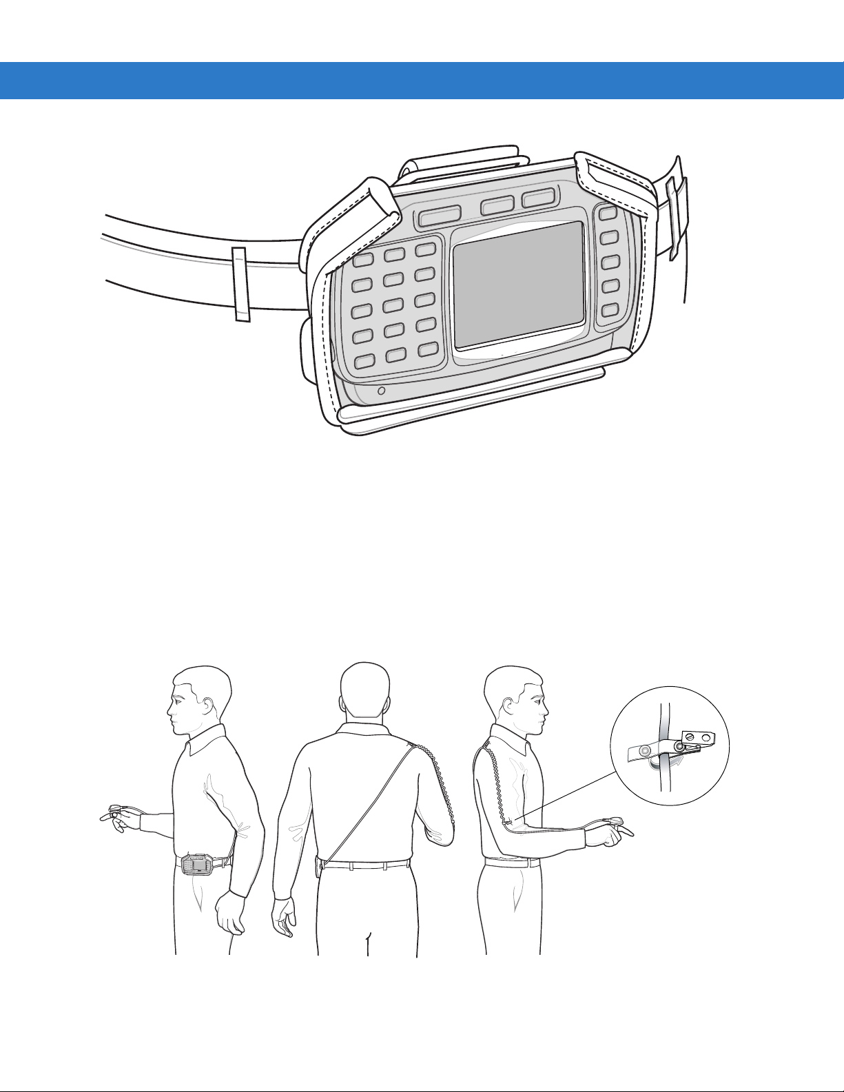
Getting Started 1 - 13
Figure 1-15
Connect accessories as required.
Hip Mount on Belt
Routing an Extended Cable Scanner
When using an RS309 or RS409 scanner with the wearable terminal mounted on the hip, the extended cable
version is required.
Zebra offers for sale cable clips, which attach to clothing and hold the scanner cable so that the cable does not
interfere with the user. The cable clips are similar to badge clips and can be purchased at any office supply store as
well.
Figure 1-16
Routing RS409 Scanner Cable from Hip to Hand
Page 30

1 - 14 WT4070/90 Wearable Terminal User Guide
Figure 1-17
Routing RS309 Scanner Cable from Hip to Hand
Connecting a Scanner
The RS309 and RS409 scanners and the RS507 imager can be used with the wearable terminal. See RS309
Scanner on page 3-10 and RS409 Scanner on page 3-8 for procedures for connecting the scanner to the wearable
terminal. Refer to the RS507 Product Reference Guide for procedures for connecting the imager to the wearable
terminal.
Starting the Wearable Terminal
Press the Power button to turn on the wearable terminal. If the wearable terminal does not power on, perform a
cold boot. See Resetting the Wearable Terminal on page 2-17.
NOTE When a battery is fully inserted in a wearable terminal for the first time, upon the wearable terminal’s first
power up, the device cold boots and powers on automatically.
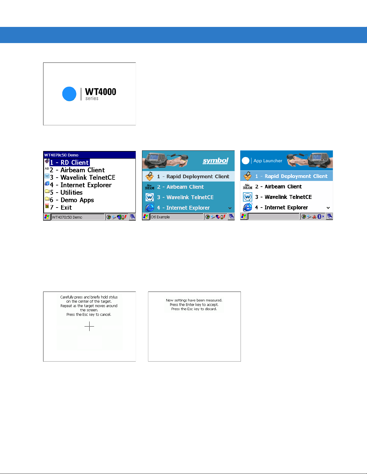
WT4070/90 Boot Up
When the WT4070/90 is powered on for the first time the splash screen (Figure 1-18) appears for a short period of
time followed by the Start Up window on non-touch configurations and the calibration screen on touch enabled
configurations.
Page 31
Getting Started 1 - 15
OEM VERSION 02.17.0001
OEM VERSION 03.17.0001
OEM VERSION 04.20.0004 or
05.30.0001
Calibration Screen Confirm Calibration
Screen
Figure 1-18
Figure 1-19
Use the
1. Carefully press and briefly hold on the center of the Calibration screen target. Repeat the procedure as the
Splash Screen
Start Up Window
Calibration screen to align the touch screen:
target moves and stops at different locations on the screen. This enters the new calibration settings.
Figure 1-20
2. Once all of the new calibration settings are input, tap the screen or press the ENTER button to save the new
calibration settings. Press
Calibration Screen
ESC to discard the new calibration settings.
Voice Only WT4090 Boot Up
When the Voice Only WT4090 is powered on for the first time the three LEDs on the front housing blink as follows:
Page 32

1 - 16 WT4070/90 Wearable Terminal User Guide
1. Application Controlled LED and Battery Status LED on.
2. All LEDs Off.
3. Application Controlled LED on, Battery Status LED on, WLAN Status LED on.
4. WLAN Status LED off, Battery Status LED off, Application Controlled LED off.
The WLAN Status LED blinks indicating that the wireless connection is not connected or is solid indicating that the
wireless connection is connected.
Page 33

Chapter 2 Using the Wearable Terminal
Power Button
Introduction
This chapter explains the physical buttons and controls on the wearable terminal, and provides basic instructions
for using the wearable terminal, including powering on and resetting the wearable terminal, using a headset,
entering information and scanning.
This chapter also details the operation of the Windows CE 5.0 operating system including the desktop, applications
and settings. Depending upon the programs installed on the wearable terminal, some of these items may not be
available.
Power Button
Press the Power button to turn the wearable terminal screen on and off (suspend mode). The wearable terminal is
on when the screen is on and the wearable terminal is in suspend mode when the screen is off. For more
information, see Starting the Wearable Terminal on page 1-14.
Figure 2-1
The Power button is also used to reset the wearable terminal by performing a warm or cold boot.
•
•
Power Button
Warm Boot (Soft Reset) - Resets the wearable terminal.
Cold Boot (Hard Reset) - Resets the wearable terminal, removes all added applications and restores all
factory default settings.
Page 34

2 - 2 WT4070/90 Wearable Terminal User Guide
Charge Status LED
LED Indicators
The Charge Status LED indicates the wearable terminal charging status when the WT4090 is in a cradle. Table 2-1
describes the Charge Status LED indications.
Figure 2-2
Table 2-1
Charge Status LED Off Wearable terminal is not in cradle. Wearable terminal
Wearable Terminal LED Indicators
Charge Status LED Indications
LED State Indication
not placed correctly. Charger is not powered.
Slow Blinking Amber Main battery in
Fast Blinking Amber Charging error:
•
Temperature is too low or too high.
•
Charging has gone on too long without
completing (typically eight hours).
Solid Amber Charging complete.
Note: When the battery is initially inserted in the
wearable terminal
battery power is low or the battery is not fully inserted.
wearable terminal
, the amber LED flashes once if the
is charging.
Page 35

Using the Wearable Terminal 2 - 3
WLAN Status LED
Application
Controlled LED
Battery Status LED
Charging Status LED
Figure 2-3
The Voice Only WT4090 has three status LEDs. Table 2-2 lists the default LED indications. LED functionality can
be changed by an application.
Table 2-2
WLAN Status LED (Green) Off Battery completely discharged or device error. Contact
Battery Status LED (Light
Green)
Application Controlled LED
(Yellow)
Voice Only WT4090 LED Indicators
Voice Only WT4090 LED Indications
LED State Indication
system administrator.
Blinking Voice Only WT4090 is not connected to a wireless
network.
Solid Voice Only WT4090 is connected to a wireless
network.
Off Battery charge level is greater than 30%
Blinking Battery charge level is less than 30%.
- Application dependent.
Page 36

2 - 4 WT4070/90 Wearable Terminal User Guide
Keypads
The wearable terminal has the following keypads:
•
Two-color alphanumeric keypad
•
Triple-tap (cell phone like) alphanumeric keypad
•
Voice Only keypad.
Two-color Alphanumeric Keypad
The two-color alphanumeric keypad contains application keys, scroll keys and function keys. The keypad is
color-coded to indicate the alternate function keys (blue, orange and gray). Note that keypad functions can be
changed by an application so the wearable terminal’s keypad may not function exactly as described. See Table 2-3
on page 2-4 for key and button descriptions and Table 2-5 on page 2-7 for the keypad’s special functions.
Figure 2-4
Table 2-3
Orange Press and release the Orange key to activate alphabetic characters (shown on the
Gray Press and release the Gray key to activate alphabetic characters (shown on the keypad in
Two-color Alphanumeric Keypad
Two-color Alphanumeric Keypad Descriptions
Key Description
keypad in orange). The icon appears on the Windows CE desktop taskbar.
gray). The icon appears on the Windows CE desktop taskbar.
Page 37

Using the Wearable Terminal 2 - 5
Table 2-3
Two-color Alphanumeric Keypad Descriptions (Continued)
Key Description
Blue Press and release the Blue key to activate the keypad alternate functions (shown on the
keypad in blue). The icon appears on the Windows CE desktop taskbar.
Scroll Keys Moves up or down from one item to another or increases/decreases specified values.
Moves left or right from one item to another when used with the Blue key. For each left or
right scroll, the Blue key must be pressed first.
ESC Exits the current operation.
Alphanumeric In default state, produces the numeric value on the key.
In Left Alpha state, produces the lower case alphabetic characters in the orange area. In
Right Alpha state, produces the lower case alphabetic characters in the gray area.
When the
SHIFT
key is pressed in the Alpha state, the upper case alphabetic characters
on the key are produced. For example, press and release the Orange key, press and
release the
SHIFT
key and then press the 4 key once to produce the letter ‘G’.
BKSP Backspace function. Space function when used with the Blue key.
CTRL (Control) Press and release the CTRL key to activate the keypad alternate CTRL functions. The
icon appears on the Windows CE desktop taskbar.
Press the Blue key followed by the CTRL key to activate the keypad alternate ALT
functions. The icon appears on the Windows CE desktop taskbar.
SHIFT Press and release the SHIFT key to activate the keypad alternate SHIFT functions. The
icon appears on the Windows CE desktop taskbar.
ENTER Executes a selected item or function.
TAB Move the focus to the next field in a window.
P1 Programmable key. When used with the Blue key, toggles the keypad backlight on and
off.
P2 Programmable key. When used with the Blue key, toggles the display backlight on and off.
Page 38

2 - 6 WT4070/90 Wearable Terminal User Guide
Triple-Tap Alphanumeric Keypad
The triple-tap alphanumeric keypad contains application keys, scroll keys and function keys. The keypad is
color-coded to indicate the alternate function keys (blue and orange). Note that keypad functions can be changed
by an application so the wearable terminal’s keypad may not function exactly as described. See Table 2-4 on page
2-6 for key and button descriptions and Table 2-5 on page 2-7 for the keypad’s special functions.
Figure 2-5
Table 2-4
Orange Press and release the Orange key to activate alphabetic characters (shown on the keypad in
Blue Press and release the Blue key to activate the keypad alternate functions (shown on the keypad
Scroll Keys Moves up or down from one item to another or increases/decreases specified values.
ESC Exits the current operation.
Triple-tap Alphanumeric Keypad
Triple-tap Alphanumeric Keypad Descriptions
Key Description
orange). The icon appears on the Windows CE desktop taskbar.
in blue). The icon appears on the Windows CE desktop taskbar.
Moves left or right from one item to another when used with the Blue key. For each left or right
scroll, the Blue key must be pressed first.
Page 39

Using the Wearable Terminal 2 - 7
Table 2-4
Triple-tap Alphanumeric Keypad Descriptions (Continued)
Key Description
Alphanumeric In default state, produces the numeric value on the key.
In Alpha state, produces the lower case alphabetic characters shown in orange text. For
example, press and release the Orange key and then press the
lowercase letter ‘k’.
When the
SHIFT
key is pressed in Alpha state, the upper case alphabetic characters on the key
are produced. For example, press and release the Orange key, press and release the
and then press the
5
key twice to produce the uppercase letter ‘K’.
BKSP Backspace function. Space function when used with the Blue key.
CTRL (Control)
Press and release the CTRL key to activate the keypad alternate CTRL functions. The icon
appears on the Windows CE desktop taskbar.
Press the Blue key followed by the CTRL key to activate the keypad alternate ALT functions. The
icon appears on the Windows CE desktop taskbar.
SHIFT
Press and release the SHIFT key to activate the keypad alternate SHIFT functions. The icon
appears on the Windows CE desktop taskbar.
ENTER Executes a selected item or function.
TAB Move the focus to the next field in a window.
5
key twice to produce the
SHIFT
key
P1 Programmable key. When used with the Blue key, toggles the keypad backlight on and off.
P2 Programmable key. When used with the Blue key, toggles the display backlight on and off.
P3 Programmable key.
The keypad is color-coded to indicate the alternate function key (blue) values and the alternate ALPHA key
(orange) values. See Table 2-5 for the special character generation.
Table 2-5
Special Character Generation Map
Special Character Two-color Keypad Triple-tap Keypad
/
Blue - Orange -
0
Blue - Orange -
0
(forward slash)
[
Blue - Orange -
2
Blue - Orange -
2
(open square bracket)
]
Blue - Orange -
3
Blue - Orange -
3
(close square bracket)
\
Blue - Orange -
4
Blue - Orange -
4
(Backslash)
`
Blue - Orange -
5
Blue - Orange -
5
(apostrophe)
,
(comma)
Blue - Orange -
6
Blue - Orange -
6
Page 40

2 - 8 WT4070/90 Wearable Terminal User Guide
Table 2-5
Special Character Generation Map (Continued)
Special Character Two-color Keypad Triple-tap Keypad
.
(period)
;
(semi-colon)
=
(equal sign)
-
(dash)
!
(exclamation point)
@
(at sign)
#
(Pound sign)
$
(dollar sign)
7
Blue - Orange Orange -
TAB
Blue - Orange -
Blue - Orange -
Blue - Orange -
or
8
9
Tab
Shift - 1Shift
Shift - 2Shift
Shift - 3Shift
Shift - 4Shift
Blue - Orange -
Blue - Orange -
Blue - Orange -
Blue - Orange -
-
1
-
2
-
3
-
4
7
8
9
Tab
%
(percent sign)
^
(carat)
&
(ampersand)
*
(asterisk)
(
(open parenthesis)
)
(close parenthesis)
‘
(single quote)
“
(double quote)
?
(question mark)
Shift - 5Shift
Shift - 6Shift
Shift - 7Shift
Shift - 8Shift
Shift - 9Shift
Shift - 0Shift
Blue - Orange -
Shift
- Blue - Orange -
Shift
- Blue - Orange -
1
1Shift
0Shift
-
5
-
6
-
7
-
8
-
9
-
0
Blue - Orange -
- Blue - Orange -
- Blue - Orange -
1
1
0
{
(open curly bracket)
Shift
- Blue - Orange -
2Shift
- Blue - Orange -
2
Page 41

Using the Wearable Terminal 2 - 9
Table 2-5
}
(close curly bracket)
|
(pipe)
~
(tilde)
<
(less than sign)
>
(greater than sign)
:
(colon)
+
(plus sign)
_
(underscore)
Special Character Generation Map (Continued)
Special Character Two-color Keypad Triple-tap Keypad
Shift
- Blue - Orange -
Shift
- Blue - Orange -
Shift
- Blue - Orange -
Shift
- Blue - Orange -
Shift
- Blue - Orange -
Shift
- Blue - Orange -
Shift
- Blue - Orange -
Shift
- Blue - Orange -
3Shift
4Shift
5Shift
6Shift
7Shift
8Shift
9Shift
Tab Shift
- Blue - Orange -
- Blue - Orange -
- Blue - Orange -
- Blue - Orange -
- Blue - Orange -
- Blue - Orange -
- Blue - Orange -
- Blue - Orange -
3
4
5
6
7
8
9
Tab
Voice Only Keypad
The voice only keypad contains three programmable function keys.
Figure 2-6
Voice Only Keypad
Page 42

2 - 10 WT4070/90 Wearable Terminal User Guide
OEM VERSION 02.17.0001
OEM VERSION 03.17.0001 OEM VERSION 04.20.0004 or
05.30.0001
Display
NOTE To view the software versions on the Voice Only WT4090, the Voice Only WT4090 must be
connected to a host computer running remote desktop software. See the WT4070/90 Wearable
Terminal Integrator Guide for more information.
The wearable terminal is factory installed with the Windows CE 5.0 operating system. When the wearable terminal
starts, it automatically launches the Start Up application.
NOTE A customer specific application can be configured to automatically start-up and the Windows CE
5.0 desktop and Start Up application might not be visible or accessible.
Start Up Window
NOTE Start Up menu does not automatically launch on the Voice Only WT4090.
The Start Up window allows the user to launch specific applications by using the keypad. Either scroll up and down
using the arrow keys and select
Start Up window is closed, launch the Start Up window by selecting OTL on the desktop.
Figure 2-7
Table 2-6
RD Client or Rapid
Deployment Client
Start-up Window
Start Up Item Descriptions
Item
Enter to select an item or press the numeric key associated with the item. If the
Launch
Number
1 Launches the Rapid Deployment application. Refer to the WT4070/90
Wearable Terminal Integrator Guide for more information.
Description
AirBEAM Client 2 Launches the AirBEAM Client application. Refer to the WT4070/90
Wavelink TelnetCE 3 Launches the Wavelink Client application.
Internet Explorer 4 Launches the Microsoft Pocket Internet Explorer application.
Wearable Terminal Integrator Guide for more information.
Page 43

Using the Wearable Terminal 2 - 11
Start Button
Open Program
Status Icons
Desktop Button
Clock
Table 2-6
Start Up Item Descriptions (Continued)
Item
Launch
Number
Description
Utilities folder 5 Opens a sub-window that contains utilities, such as: Control Panel, File
Explorer, BT HID Connect, BT Printer Connect and test applications. For
more information on the Control Panel and File Explorer, refer to the
Application Guide, p/n 72E-68901-xx.
Demo Apps 6 Opens a sub-window that contains sample demonstration applications.
Exit 7 Closes the Start Up window.
Windows CE 5.0 Desktop
The following paragraphs describe the Windows CE 5.0 desktop. Depending upon the customer’s configuration of
the wearable terminal, the desktop may not be available.
Status Icons
The Taskbar at the bottom of the window displays the active programs, current time, battery status and
communication status.
Figure 2-8
Taskbar
Page 44

2 - 12 WT4070/90 Wearable Terminal User Guide
Status icons are shown in the taskbar to indicate present status of the wearable terminal.
Table 2-7
Status
Icon
Status Icons
Description
Indicates the current time. The clock can be toggled on and off. Select
Panel
>
Task and Start Menu
.
Start
>
Settings
This icon indicates that the main battery is charging or that the wearable terminal is operating on
external power.
Indicates that the battery is fully charged and the
wearable terminal
is running on external power.
This icon is displayed when the memory backup battery level is low. Charge the battery.
This icon indicates that the battery is fully charged (100% charged).
The battery status icons provide the battery status in 10% increments from 10% to 100%.
This displays when the terminal is connected to a host computer with ActiveSync.
Wireless connection status icon. Indicates WLAN signal strength.
Bluetooth radio is on.
>
Control
Bluetooth radio is off.
Bluetooth radio is connected to another Bluetooth device.
Indicates that the
Indicates that the Blue
Indicates that the
Indicates that the
Indicates that the Orange
Indicates that the Gray
SHIFT
key is selected.
key is selected.
CTRL
key is selected.
ALT
key is selected.
key is selected.
key is selected.
Indicates that the Remote Control software is connected to the wearable terminal.
Using the Keypad to Navigate Applications
NOTE Not available on the Voice Only configuration.
Page 45

Using the Wearable Terminal 2 - 13
Highlighted Item
On wearable computers without touch-enabled screens navigation and control of an application is performed using
the keypad.
Key Combinations
The wearable terminal uses special key combinations to easily navigate applications. Table 2-8 lists the key
combinations required to perform various application navigation and control functions.
Table 2-8
Key Combinations
Action Key Combination
Access the Start menu on the taskbar
Switch fields within an application
Close windows or cancel operations on some applications
Access the Task Manager
Switches to the next window or desktop
Access a menu bar in an application
Press a button or select a check box in an application
Display a pop-up context menu
CTRL-ESC
TAB
ESC or ALT - F4
ALT-TAB
ALT-ESC
ALT-ALT
TAB
until the item is highlighted then
ALT-ENTER
SPACE
.
Throughout this guide you will be instructed to select an item. You must use a key combination to select that item.
For example:
To perform:
“Select
1. Press CTRL and then ESC to open the Start menu.
Start > Programs > Windows Explorer”
2. Press the up arrow until the Programs item is highlighted.
3. Press the Blue key and the down arrow to open the Programs sub-menu.
4. Press the down arrow until Windows Explorer is highlighted.
5. Press ENTER key to launch Windows Explorer.
Selecting Items
When using the navigation keys to perform tasks in an application, the active item is highlighted using either a color
background and/or a dashed box.
Figure 2-9
Highlighted Items
Page 46

2 - 14 WT4070/90 Wearable Terminal User Guide
Selected Tab
Navigating Menus
Most applications have drop-down menus to perform specific functions. Use the key combination ALT - ALT to open
a menu. Once the menu is open, use the up and down navigation keys to move up and down the menu and use the
left and right navigation keys to move to the next menu item or open a sub-menu. When moving through a menu,
items are highlighted. Once an item is highlighted, press the
ENTER key to select that item.
Figure 2-10
Navigating Menus
Navigating Tabs
Some applications contain multiple pages with tabs indicating each page. Use the TAB key to highlight the tab. A
dashed box appears around the tab name. Use the left and right navigation keys to move to the next or previous
tab.
Figure 2-11
Navigating Tabs
Navigating Fields
To navigate from one field to another, press the TAB key. Repeated pressing of the TAB key cycles the highlighted
cursor through the fields in the window.
Selecting Checkboxes and Radio Buttons
To select or deselect checkboxes and radio buttons press the TAB key until the field is highlighted. Press ALT -
BKSP (SPACE) to select or deselect the checkbox or radio button.
Page 47

Using the Wearable Terminal 2 - 15
Highlighted Checkbox
Radio Buttons
Figure 2-12
Selecting a Checkbox or Radio Button
Selecting Items in a List
Use a combination of key sequences to select items in a folder or list.
To select continuous items in a folder or list:
1. Open the folder or list.
2. Use the scroll keys to move to the first item to select.
3. Press SHIFT - scroll key (either up or down) to select the next item.
4. Repeat the SHIFT - scroll key combination to select remaining items.
5. Perform the desired function.
To select multiple items in a folder or list:
1. Open the folder or list.
2. Use the scroll keys to move to the first item.
3. Press CTRL - scroll key to move within the list. The item name is outlined.
4. Repeat step 3 to move to the desired item.
5. Press SPACE to highlight the item.
6. Repeat steps 3 through 5 until all items are selected.
7. Perform the desired function.
Screen Calibration
NOTE Not available on the Voice Only and non-touch configurations.
To calibrate the touch screen so the cursor on the touch screen aligns with screen taps:
1. Press Start > Settings > Control Panel > Stylus icon > Calibration tab > Recalibrate button.
2. Carefully press and briefly hold on the center of the Calibration screen target. Repeat the procedure as the
target moves and stops at different locations on the screen. This enters the new calibration settings.
Page 48

2 - 16 WT4070/90 Wearable Terminal User Guide
Calibration Screen Confirm Calibration
Screen
Figure 2-13
3. Once all of the new calibration settings are input, tap the screen or press the ENTER button to save the new
Calibration Screen
calibration settings. Press
Special Character Keypad
NOTE The Special Character Keypad is only available on non-touch screen configurations with a display.
The wearable terminal contains an on-screen Special Character keypad that allows users to enter alphanumeric
and special characters. The keypad looks and functions like a standard keyboard.
To display the Special Character keypad, press the key on the keyboard.
ESC to discard the new calibration settings.
Figure 2-14
Special Character Keypad - Alphanumeric Layer
Use the arrow keys on the keyboard to move the yellow box to highlight a key on the Special Character keypad.
The arrow keys wrap to the next row or column as you navigate with the keys.
To select a character, press the Enter key on the wearable terminal.
If the Enter or arrow keys need to be used by the application instead of the Special Character keypad, press Esc
followed by the arrow or Enter key. This sends the key to the application instead of the Special Character keypad.
Press the ABC key on the Special Character keypad to switch between the alphanumeric layer and the character
layer.
Page 49

Using the Wearable Terminal 2 - 17
Figure 2-15
Navigate the keypad in the same manner as described above. To return to the alphanumeric layer, press the CH
key on the keypad.
Pressing CAP or SH switches the keypad to the upper case alphanumeric keypad.
Figure 2-16
Press the key to close the Special Character keypad.
Special Character Keyboard - Character Layer
Special Character Keyboard in upper case Alphanumeric Mode
Resetting the Wearable Terminal
There are two types of resets, warm boot and cold boot. A warm boot restarts the wearable terminal by closing all
running programs.
A cold boot also restarts the wearable terminal, but erases all stored records and entries in RAM. Data saved in
flash memory or a memory card is not lost. In addition it returns formats, preferences and other settings to the
factory default settings.
Perform a warm boot first. This restarts the wearable terminal and saves all stored records and entries. If the
wearable terminal still does not respond, perform a cold boot.
Performing a Warm Boot
Hold down the Power button for approximately five seconds. As soon as the wearable terminal starts to perform a
warm boot release the Power button.
Page 50

2 - 18 WT4070/90 Wearable Terminal User Guide
Performing a Cold Boot
A cold boot restarts the wearable terminal and erases all user stored records and entries that are not saved in flash
memory (Application and Platform folders). Never perform a cold boot unless a warm boot does not solve the
problem.
NOTE Any data previously synchronized with a computer can be restored during the next ActiveSync operation.
To perform a cold boot on a WT4070/90 press and simultaneously hold the
down any other keys or buttons. The wearable terminal initializes.
To perform a cold boot on a Voice Only WT4090 press and simultaneously hold the P1 and P2 keys and the Power
button. The wearable terminal initializes.
1, 9 and Power button. Do not hold
Page 51

Data Capture
Wearable terminals used with an optional wearable laser scanner allow collection of data by scanning one
dimensional bar codes.
Laser Scanning
Wearable terminals with an optional wearable laser scanner have the following features:
•
Reading of a variety of bar code symbologies, including the most popular linear, postal, and 1-D code types.
•
Advanced intuitive laser aiming for easy point-and-shoot operation.
Scanning Considerations
Typically, scanning is a simple matter of aim, scan/decode and a few quick trial efforts master it. However, two
important considerations can be used to optimize any scanning performance:
•
Range
Using the Wearable Terminal 2 - 19
Any scanning device decodes well over a particular working range — minimum and maximum distances from
the bar code. This range varies according to bar code density and scanning device optics.
Scanning within range brings quick and constant decodes; scanning too close or too far away prevents
decodes. Move the scanner closer and further away to find the right working range for the bar codes being
scanned. However, the situation is complicated by the availability of various integrated scanning modules. The
best way to specify the appropriate working range per bar code density is through a chart called a decode zone
for each scan module. A decode zone simply plots working range as a function of minimum element widths of
bar code symbols.
•
Angle
Scanning angle is important for promoting quick decodes. When laser beams reflect directly back into the
scanner from the bar code, this specular reflection can “blind” the scanner.
To avoid this, scan the bar code so that the beam does not bounce directly back. But don’t scan at too sharp an
angle; the scanner needs to collect scattered reflections from the scan to make a successful decode. Practice
quickly shows what tolerances to work within.
NOTE Contact the Zebra Support Center if chronic scanning difficulties develop. Decoding of properly printed bar
codes should be quick and effortless.
Scanning Bar Codes
1. Ensure that a scan enabled application is loaded on the wearable terminal.
2. Aim the scan exit window at the bar code.
3. Press the trigger.
•
Ensure the red scan beam covers the entire bar code. The red scan LED lights to indicate that the laser is
on. The green scan LED lights. An audible beep might sound, if the application determines, to indicate the
bar code was decoded successfully.
Page 52

2 - 20 WT4070/90 Wearable Terminal User Guide
Figure 2-17
4. Release the trigger.
Laser Scanner Aiming Pattern
Scanning Tips
Optimal scanning distance varies with bar code density and scanner optics.
•
Hold the scanner farther away for larger symbols.
•
Move the scanner closer for symbols with bars that are close together.
NOTE Scanning procedures depend on the application and wearable terminal configuration. An application may
use different scanning procedures from the one listed above.
Scan LED Indicator
The LED on the scanner provides a visual indication of the scan status.
Table 2-9
Off Not scanning.
Solid Red Laser enabled, scanning in process.
Scan LED Indicators
LED Status Indication
Solid Green Successful decode.
Imaging
The wearable terminal with an optional RS507 imager has the following features:
•
Omnidirectional (360°) reading of a variety of bar code symbologies, including the most popular linear, postal,
PDF417, and 2D matrix code types.
•
The ability to capture and download images to a host for a variety of imaging applications.
•
Advanced intuitive laser aiming for easy point-and-shoot operation.
The imager uses digital camera technology to take a digital picture of a bar code, stores the resulting image in its
memory, and executes state-of-the-art software decoding algorithms to extract the data from the image.
Operational Modes
The wearable terminal with optional RS507 imager supports three modes of operation, listed below. Activate each
mode pressing the Scan button.
•
Decode Mode: In this mode, the RS507 attempts to locate and decode enabled bar codes within its field of
view. The imager remains in this mode as long as you hold the scan button, or until it decodes a bar code.
Page 53

NOTE To enable Pick List Mode, download the Control Panel applet from the Support Central web site at
http://www.
•
Pick List Mode: This mode allows you to selectively decode a bar code when more than one bar code is in
zebra.com/support. Pick List can also be set in an application using a API command.
the RS507’s field of view. To accomplish this, move the aiming crosshair center dot over the required bar
code to decode only that bar code. This feature is ideal for pick lists containing multiple bar codes and
manufacturing or transport labels containing more than one bar code type (either 1D or 2D).
•
Image Capture Mode: Use this mode to capture an image within the RS507’s field of view. This is useful for
capturing signatures or images of items like damaged boxes.
Imager Scanning
1. Ensure that a scan-enabled application is loaded on the wearable terminal.
2. Press and hold the scan button.
The red laser aiming pattern turns on to assist in aiming. Ensure the cross-hair is on top of the bar code.
The Decode LED lights red to indicate that scanning is in process, then lights green and a beep sounds, by
default, to indicate the bar code was decoded successfully. Note that when the RS507 is in Pick List Mode, the
imager does not decode the bar code until the crosshair center dot touches the bar code.
Using the Wearable Terminal 2 - 21
Figure 2-18
Figure 2-19
3. Release the scan button.
Imager Aiming Pattern
Pick List Mode with Multiple Bar Codes
NOTE Imager decoding usually occurs instantaneously. The RS507 repeats the steps required to take a digital
picture (image) of a poor or difficult bar code as long as the scan button remains pressed.
Page 54

2 - 22 WT4070/90 Wearable Terminal User Guide
Waking the Wearable Terminal
The wake up conditions define what actions wake up the wearable terminal after it has gone into suspend mode.
The wearable terminal can go into suspend mode by either pressing the Power button or automatically by control
panel time-out settings. These settings are configurable and the factory default settings are shown in Table 2-10.
Table 2-10
AC power is applied. No Yes
Wearable terminal is inserted into a cradle. No Yes
Wearable terminal is removed from a cradle. No Yes
Wearable terminal is connected to a serial device. No Yes
Wearable terminal is connected to a USB device. No Yes
Wearable terminal is disconnected from a USB
device.
A key is pressed. No Yes
An attached scanner is triggered. No Yes
Wireless LAN activity is detected. No No
A headset is connected to the wearable terminal. No Yes
Screen Touch (only on touch screen configurations) No No
Wakeup Default Settings
Condition for Wakeup Power Button Automatic Time-out
No Yes
NOTE If the battery is removed and replaced, the only way to wake up the terminal is by pressing the Power button.
Page 55

Chapter 3 Accessories
Introduction
The wearable terminal accessories provide a variety of product support capabilities. Accessories include cradles,
cables and scanners.
Cradles
•
Single Slot USB cradle charges the wearable terminal main battery and a spare battery. It also synchronizes
the wearable terminal with a host computer through either a serial or a USB connection.
•
Four Slot Ethernet cradle charges up to four wearable terminal batteries and synchronizes the wearable
terminals with a host computer through an Ethernet connection.
•
Four Slot Spare Battery Charger charges up to four wearable terminal spare batteries.
Scanners
•
RS309 scanner
•
RS409 scanner
•
RS507 imager.
Accessories
•
Freezer pouch
•
Hip Mount
•
Wired Headset
•
Connector shroud.
Page 56

3 - 2 WT4070/90 Wearable Terminal User Guide
Spare Battery
Spare Battery
Charging LED
Scanner Placed in Well
Single Slot USB Cradle
CAUTION Ensure that you follow the guidelines for battery safety described in Battery Safety Guidelines on page 4-3.
This section describes how to use a Single Slot USB cradle (Figure 3-1) with the wearable terminal. For USB
communication setup procedures refer to the WT4090 Integrator Guide.
Figure 3-1
The Single Slot USB Cradle:
Single Slot USB Cradle
CAUTION Use only anapproved power supply output rated 12 VDC and minimum 3.3 A. Use of an alternative power
supply will void the product warranty and may cause product damage. See Appendix B, Regulatory
Information for the power supply regulatory compliance statement.
•
Provides 5.4 VDC power for operating the wearable terminal.
•
Provides USB port for data communication between the wearable terminal and a host computer or other
serial devices (e.g., a printer).
NOTE The normal function of the product may be disturbed by Strong Electro Magnetic Interference (for
example, static electricity). If so, simply remove and re-insert the terminal to resume normal operation.
In case the function does not resume, please use the product in another location.
Page 57

Accessories 3 - 3
•
Synchronizes information between the wearable terminal and a host computer. (With customized or third
party software, it can also be used to synchronize the wearable terminal with corporate databases.)
•
Charges the wearable terminal’s battery and a spare battery.
•
Provides a location for storing a scanner when a wearable terminal is docked in the cradle.
Battery Charging Indicators
The Single Slot USB cradle can charge the wearable terminal’s main battery and a spare battery simultaneously.
The wearable terminal’s amber Charge Status LED indicates the status of the battery charging in the wearable
terminal. See Table 1-3 on page 1-8 for charging status indications.
The amber Spare Battery Charging LED on the cradle (see Figure 3-1 on page 3-2) indicates the status of the
spare battery charging in the cradle. See Table 3-1 for charging status indications. The standard capacity battery
fully charges in less than four hours and the extended capacity battery fully charges in less than eight hours.
Table 3-1
Spare Battery LED
Off No spare battery in well; spare battery not placed correctly; cradle is not powered.
Fast Blinking Amber Charging error:
Slow Blinking Amber Spare battery is charging.
Solid Amber Charging complete.
Spare Battery LED Charging Indicators
(on cradle)
•
Temperature is too low or too high.
•
Charging has gone on too long without completing (typically eight hours).
Indication
Page 58
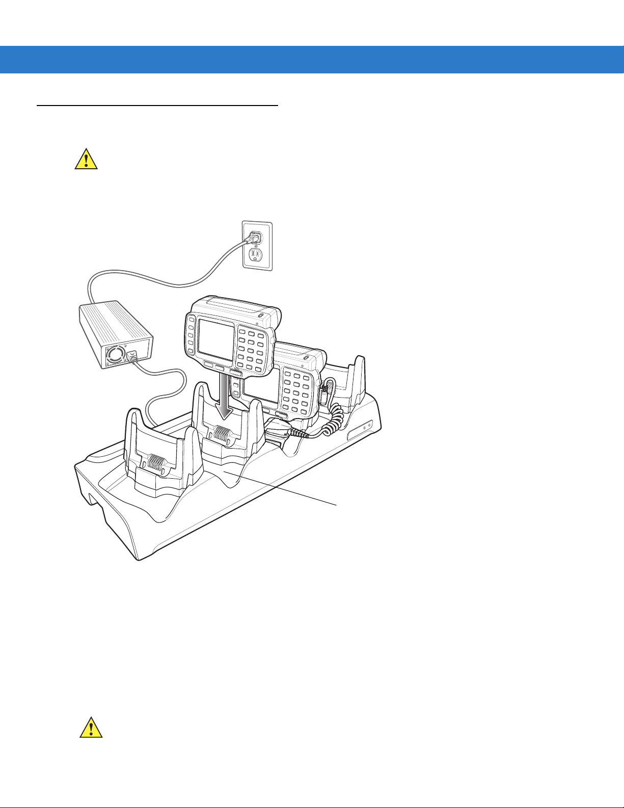
3 - 4 WT4070/90 Wearable Terminal User Guide
Scanner Well
Four Slot Ethernet Cradle
CAUTION Ensure that you follow the guidelines for battery safety described in Battery Safety Guidelines on page 4-3.
This section describes how to use a Four Slot Ethernet cradle (Figure 3-2) with the wearable terminal. For Ethernet
communication setup procedures refer to the WT4090 Integrator Guide.
Figure 3-2
The Four Slot Ethernet cradle:
•
•
•
You cannot ActiveSync using the Four Slot Ethernet cradle. To ActiveSync with a host computer use the Single Slot
USB cradle.
Four Slot Ethernet Cradle
Connects up to four wearable terminals to an Ethernet network.
Provide 5.4 VDC power for operating the wearable terminal and charging the battery.
Simultaneously charges up to four wearable terminals (with batteries installed).
CAUTION Use only an approved power supply output rated 12 VDC and minimum 9 A. Use of an alternative power
supply will void the product warranty and may cause product damage. See Appendix B, Regulatory
Information for the power supply regulatory compliance statement.
Page 59

Accessories 3 - 5
Battery Charging
The four slot Ethernet cradle can charge up to four wearable terminals simultaneously. To charge the wearable
terminal:
1. Slide the wearable terminal into the wearable terminal slot.
2. The wearable terminal amber Charge Status LED indicates the wearable terminal battery charging status. The
standard capacity battery usually charges in less than four hours and the extended capacity battery fully
charges in less than eight hours. See Table 3-1 for charging status indications.
3. When charging is complete, remove the wearable terminal from the cradle.
LED Charge Indications
The Four Slot Ethernet cradle uses the wearable terminal amber Power LED to indicate the battery charging
status. See Table 3-1 on page 3-3 for charging status indications.
Speed LED
The green Speed LED lights to indicate that the transfer rate is 100 Mbps. When it is not lit it indicates that the
transfer rate is 10 Mbps.
Link LED
The yellow Link LED blinks to indicate activity, or stays lit to indicate that a link is established. When it is not lit, it
indicates that there is no link.
Battery Charging Indicators
The wearable terminal’s amber charge LED indicates the status of the battery charging in the wearable terminal.
See Table 1-3 on page 1-8 for charging status indications.
The standard capacity battery fully charges in less than four hours and the extended capacity battery fully charges
in less than eight hours.
Page 60

3 - 6 WT4070/90 Wearable Terminal User Guide
Spare Battery Charging LEDs (4)
Spare Battery
Spare Battery Charging Well (4)
Four Slot Spare Battery Charger
CAUTION Ensure that you follow the guidelines for battery safety described in Battery Safety Guidelines on page 4-3.
This section describes how to use the Four Slot Spare Battery Charger to charge up to four wearable terminal
spare batteries.
Figure 3-3
Four Slot Spare Battery Charger
CAUTION Use only an approved power supply output rated 12 VDC and minimum 3.3 A. Use of an alternative power
supply will void the product warranty and may cause product damage. See Appendix B, Regulatory
Information for the power supply regulatory compliance statement.
Spare Battery Charging with the Four Slot Spare Battery Charger
Insert the battery into a spare battery charging slot and gently press down on the battery to ensure proper contact.
Battery Charging Indicators
An amber LED is provided on each battery charging well. See Table 3-2 for charging status indications.The
standard capacity battery usually charges in less than four hours and the extended capacity battery fully charges in
less than eight hours.
Table 3-2
Off No spare battery in slot; spare battery not placed correctly; cradle is not powered.
Fast Blinking Amber Charging error:
Spare Battery LED Charging Indicators
LED Indication
•
Temperature is too low or too high.
•
Charging has gone on too long without completing (typically eight hours).
Page 61

Accessories 3 - 7
Table 3-2
Slow Blinking Amber Spare battery is charging.
Solid Amber Charging complete.
Spare Battery LED Charging Indicators (Continued)
LED Indication
Page 62
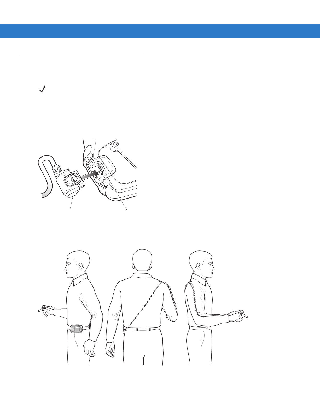
3 - 8 WT4070/90 Wearable Terminal User Guide
Scanner Cable Connector
Interface Connector
RS409 Scanner
To connect the RS409 scanner to the wearable terminal:
NOTE There are two RS409 configurations available. The short cable configuration connects the RS409 to the
wearable terminal mounted on the arm. The extended cable configuration connects the RS409 to the WT4090
mounted on the hip.
1. Remove the rubber plug from the wearable terminal interface connector.
2. Connect the RS409 interface cable to the wearable terminal interface connector. If the wearable terminal is
mounted on the arm, connect the cable to the interface connector closest to the wrist.
Figure 3-4
3. If using the extended cable configuration, route the scanner cable up to the shoulder and down to the hand that
Connecting RS409 to Wearable Terminal
the scanner mounts on. Attach two cable clips to clothing and secure cable to cable clip.
Figure 3-5
Cable Clip Installation
4. Rotate the trigger assembly to the correct position for the hand that the scanner mounts to.
Page 63

5. Slide the RS409 onto the index finger with the scan trigger next to the thumb.
Accessories 3 - 9
Figure 3-6
6. Tighten the finger strap.
Figure 3-7
7. If required, cut excess finger strap material.
Place the RS409 on Index Finger
Tightening Straps
After connecting the scanner, warm boot the wearable terminal. See Resetting the Wearable Terminal on page
2-17 for information on performing a warm boot.
Page 64

3 - 10 WT4070/90 Wearable Terminal User Guide
Trigger Connector
RS309 Scanner
The RS309 connects to the wearable terminal and mounts on the back of either hand using the RS309 glove.
1. Remove the rubber plug from the wearable terminal interface connector.
2. Connect the RS309 trigger cable to the back of the RS309.
Figure 3-8
3. Connect the end of the RS309 interface cable to the wearable terminal interface connector. If the wearable
terminal is mounted on the arm, connect the cable to the interface connector closest to the wrist.
4. If the wearable terminal is mounted on the hip, route the interface cable up to the shoulder and down to the
hand that the scanner mounts on. Attach two cable clips to clothing and secure cable to cable clip.
Connecting Trigger Cable to RS309
Figure 3-9
Cable Clip Installation
Page 65

Accessories 3 - 11
5. Mount the RS309 on the RS309 glove. Refer to the RS309 Glove Installation Guide for information on
mounting the RS309.
6. Route the trigger cable around the side of the RS309, next to the index finger.
7. Slide the trigger mount on the index finger, with the button positioned next to the thumb, and adjust the velcro
strap.
Figure 3-10
RS309 on Back of Hand
After connecting the scanner, warm boot the wearable terminal. See Resetting the Wearable Terminal on page
2-17 for information on performing a warm boot.
Page 66

3 - 12 WT4070/90 Wearable Terminal User Guide
RS507 Imager
Refer to the RS507 Hands-free Imager Quick Reference Guide, p/n 72-115987-xx and the RS507 Hands-free
Imager Product Reference Guide, p/n 72E-120802-xx for detailed information.
Freezer Pouch
NOTE Wearable computers with standard capacity batteries must use the Standard Capacity Battery Freezer Pouch
while wearable computers with extended capacity batteries must use the Extended Capacity Battery Freezer
Pouch. See Accessories on page 1-3 for more information.
CAUTION Do not use the wearable terminal with touch screen in the freezer pouch or in environments that are
below -20°C (-4°F).
The freezer pouch allows the user to use the wearable terminal in a freezer environment on the hip or wrist for use
in voice picking applications. An RS309 or RS409 scanner with an extended cable is required when mounting the
freezer pouch on the hip mount, if scanning is also part of the application.
In order to keep the wearable terminal at a safe operating temperature in a meat or ice cream freezer, the freezer
pouch insulates the wearable terminal to keep the heat generated by the wearable terminal within the pouch. The
pouch is not heated. There are no batteries to worry about or electronics within the pouch.
The freezer pouch can be either hip-mounted or wrist-mounted. For hip-mounting, there is a belt loop on its back
for attached a belt (sold separately). For wrist-mounting, customers can buy either a set of standard-length or
longer-length wrist straps and use them with the pouch. The longer-length wrist straps are recommended for
wrist-mounting over coats. The freezer pouch has openings on each side for wearable scanners and headset
adapters.
While the freezer pouch is designed to allow workers to use the wearable terminal in meat and ice cream freezers,
there are some very important limitations to follow:
•
Do not use in environments that are below -30°C (-22°F).
•
Do not allow the wearable terminal (with or without the freezer pouch) to remain in the suspend mode in
environments below -20°C (-4°F) for more than 10 minutes. This prevents the wearable terminal from cooling
down to the ambient freezer temperature. The pouch maintains the wearable terminal at a sufficient
temperature while it is in use, but lengthy periods of inactivity bring the wearable terminal below its operating
temperature.
•
Do not store wearable terminals in the meat or ice cream freezer. As explained above, this would allow the
wearable terminals to chill to the ambient freezer temperature, which is below their operating temperature.
Furthermore, if batteries were left in wearable terminals stored in the freezer, the batteries themselves could
freeze, which could damage them. At the least, they would not function while frozen.
•
Batteries cannot be charged below 0°C (32°F). Zebra cradles and battery chargers have an automatic
shut-off to insure this.
•
If using wearable scanners with the wearable terminal in the meat or ice cream freezer for a shift, remember
that the RS309 freezer configuration is the correct scanner to choose, due to its lower operating temperature
range and its desiccant pack to remove condensation.
Slide the wearable terminal into the freezer pouch.
Page 67

Accessories 3 - 13
Figure 3-11
Close the front flap followed by the back flap.
Figure 3-12
Insert Wearable Terminal into Freezer Pouch
Close Freezer Pouch Flaps
Slide a belt through the belt loop on the back of the freezer pouch. The wearable terminal can be mounted
right-side up or up-side down depending upon user preference or application.
Page 68

3 - 14 WT4070/90 Wearable Terminal User Guide
Headset Cable Adapter
Wired Headset
You can use a mono headset with a microphone for audio communication with an audio enabled application. The
Headset Cable Adapter is required to connect a headset with the wearable terminal.
Figure 3-13
Typical Headset Connected to Headset Adapter
Page 69

Accessories 3 - 15
The headset cable adapter connects the headset to the wearable terminal. Connect the headset connect end of
the adapter to the headset connector. Plug the other end of the adapter to the wearable terminal interface
connector.
NOTE Not all headset plugs are compatible with the headset cable adapter.
CAUTION When disconnecting the headset from the headset adapter, pull the two connectors away from
each. Do not bend connectors to disconnect.
Figure 3-14
Disconnecting Headset from Headset Adapter
Figure 3-15
Headset Connected to wearable Terminal on Hip
Page 70

3 - 16 WT4070/90 Wearable Terminal User Guide
Disconnect Button
Bottom Housing
Connector Shroud
Assembly
1. Remove cable from wearable terminal, if required.
2. Align the cable connector with the connector shroud bottom housing. Ensure that the disconnect button on the
connector faces up.
Figure 3-16
3. Place the cable connector into the shroud bottom housing as shown.
Figure 3-17
4. Press the top housing into the bottom housing. The housings will snap together.
5. Plug the cable connector into the wearable terminal connector.
Installing Bottom Housing
Installing Top Housing
Disconnecting the Cable from the Wearable Terminal
NOTE Follow the instructions below when disconnecting the cable connector and shroud from the wearable terminal.
Once the shroud is installed on the connector, do not disassemble the shroud by prying it apart.
1. Turn the wearable terminal over to expose the top housing of the shroud.
2. Push the tip of a ball-point pen through the hole in the connector shroud top housing. The connector
disengages from the wearable terminal.
Page 71

Accessories 3 - 17
Connector Eject Hole
Figure 3-18
Disconnecting Connector with Shroud
Page 72

3 - 18 WT4070/90 Wearable Terminal User Guide
Page 73

Chapter 4 Maintenance & Troubleshooting
Introduction
This chapter includes instructions on cleaning and storing the wearable terminal, and provides troubleshooting
solutions for potential problems during wearable terminal operation.
Maintaining the Wearable Terminal
For trouble-free service, observe the following tips when using the wearable terminal:
•
Do not scratch the touch screen of the wearable computer. When activating with the wearable computer
touch screen, use finger tips. Never use a pen or pencil or other sharp object on the surface of the screen.
Zebra requires using a screen protector, p/n KT-114032-01R or KT-114032-02R.
•
A screen protector is applied to the wearable computer touch screen. Zebra requires using this to minimize
wear and tear. Screen protectors enhance the usability and durability of touch screen displays. Benefits
include:
• Protection from scratches and gouges
• Durable touch surface with tactile feel
• Abrasion and chemical resistance
• Keeping the device’s screen looking new
• Quick and easy installation.
•
Protect the wearable terminal with a touch screen from temperature extremes.
•
Do not store or use the wearable terminal with a touch screen in any location that is extremely dusty, damp,
or wet.
•
Use a soft lens cloth to clean the wearable terminal display/touch panel.
•
Periodically replace the rechargeable Li-ion battery to ensure maximum battery life and product performance.
Battery life depends on individual usage patterns.
•
The screen of the wearable terminal contains glass. Take care not to drop the wearable terminal or subject it
to strong impact.
Page 74

4 - 2 WT4090 Wearable Terminal User Guide
Replaceable Pad
Strap
•
Regularly replace all Velcro® straps on the wrist mount and wearable scanners, to ensure adequate
adhesion of the Velcro.
Wrist Mount Cleaning Instructions
It may be necessary to wash the wrist mount straps and replaceable pad when they become soiled.
Remove the straps and pad from the wrist mount. Hand wash in cold water with a mild detergent (such as
Woolite
Figure 4-1
®
). Do not use bleach. Air dry. Do not use a dryer.
Wrist Mount Soft Goods
Arm Sleeve Cleaning Instructions
It may be necessary to wash the arm sleeve when it become soiled.
Hand wash in cold water with a mild detergent (such as Woolite
Removing the Screen Protector
NOTE Not using a screen protector on a wearable terminal with a touch screen can affect warranty coverage. To
purchase replacement protectors, contact your local account manager or Zebra. These include screen
protector installation instructions. Part number: KT-114032-01Ror KT-114032-02R Screen Protector 3/pk.
®
). Do not use bleach. Air dry. Do not use a dryer.
A screen protector is applied to the wearable terminal with touch screen. Zebra recommends using this to minimize
wear and tear. Screen protectors enhance the usability and durability of touch screen displays.
To remove the screen protector, lift the corner using a thin plastic card, such as a credit card, then carefully lift it off
the display.
Page 75

Maintenance & Troubleshooting 4 - 3
Lift Screen
Protector
Corner
Figure 4-2
Removing the Screen Protector
CAUTION Do not use a sharp object to remove the protector. Doing so can damage the touch screen.
Battery Safety Guidelines
•
The area in which the units are charged should be clear of debris and combustible materials or chemicals.
Particular care should be taken where the device is charged in a non commercial environment.
•
Improper battery use may result in a fire, explosion, or other hazard.
•
To charge the mobile device battery, the battery and charger temperatures must be between 0 ºC and +40 ºC
(+32 ºF and +104 ºF).
•
Do not use incompatible batteries and chargers. Use of an incompatible battery or charger may present a risk
of fire, explosion, leakage, or other hazard. If you have any questions about the compatibility of a battery or a
charger, contact Zebra support.
•
Do not disassemble or open, crush, bend or deform, puncture, or shred.
•
Severe impact from dropping any battery-operated device on a hard surface could cause the battery to
overheat.
•
Do not short circuit a battery or allow metallic or conductive objects to contact the battery terminals.
•
Do not modify or remanufacture, attempt to insert foreign objects into the battery, immerse or expose to water
or other liquids, or expose to fire, explosion, or other hazard.
•
Do not leave or store the equipment in or near areas that might get very hot, such as in a parked vehicle or
near a radiator or other heat source. Do not place battery into a microwave oven or dryer.
•
Battery usage by children should be supervised.
•
Please follow local regulations to promptly dispose of used re-chargeable batteries.
•
Do not dispose of batteries in fire.
Page 76

4 - 4 WT4090 Wearable Terminal User Guide
•
Seek medical advice immediately if a battery has been swallowed.
•
In the event of a battery leak, do not allow the liquid to come in contact with the skin or eyes. If contact has
been made, wash the affected area with large amounts of water and seek medical advice.
•
If you suspect damage to your equipment or battery, contact Zebra support to arrange for inspection.
Cleaning
WARNING! Avoid exposing this product to contact with hot oil or other flammable liquids. If such exposure
occurs, unplug the device and clean the product immediately in accordance with these guidelines.
CAUTION Always wear eye protection.
Read warning label on compressed air and alcohol product before using.
If you have to use any other solution for medical reasons please contact Zebra for more information.
Materials Required
•
Alcohol wipes
•
Soft lens cloth
•
Cotton tipped applicators
•
Isopropyl alcohol
•
Can of compressed air with a tube.
Cleaning the Wearable Terminal
Housing
Using the alcohol wipes, wipe the housing including keys and in-between keys.
Display
The display can be wiped down with the alcohol wipes, but care should be taken not to allow any pooling of liquid
around the edges of the display. Immediately dried the display with a soft, non-abrasive cloth to prevent streaking.
For WT4090 with touch panel, only use a soft lens cloth to clean the touch panel overlay surface.
Connectors
Clean all three connectors, two interface connectors on the sides of the wearable terminal and the cradle
connector on the back.
1. Remove the main battery from mobile computer. See Installing and Removing the Main Battery on page 1-7.
2. Remove connector rubber plugs, if required.
3. Dip the cotton portion of the cotton tipped applicator in isopropyl alcohol.
Page 77

Maintenance & Troubleshooting 4 - 5
4. Rub the cotton portion of the cotton tipped applicator back-and-forth across each connector. Do not leave any
cotton residue on the connector.
5. Repeat at least three times.
6. Use the cotton tipped applicator dipped in alcohol to remove any grease and dirt near the connector area.
7. Use a dry cotton tipped applicator and repeat steps 4 through 7.
8. Spray compressed air on the connector areas by pointing the tube/nozzle about ½ inch away from the surface.
CAUTION Do not point nozzle at yourself and others, ensure the nozzle or tube is away from your face.
9. Inspect the area for any grease or dirt, repeat if required.
10. Replace connector rubber plugs, if required.
Cleaning the RS309, RS409 and RS507
Housing
Using the alcohol wipes, wipe the housing including keys and in-between keys.
Scanner Exit Window
Wipe the scanner exit window periodically with a lens cloth or other material suitable for cleaning optical material
such as eyeglasses.
Connectors
1. Disconnect the scanner from mobile computer.
2. Dip the cotton portion of the cotton tipped applicator in isopropyl alcohol.
3. Rub the cotton portion of the cotton tipped applicator back-and-forth across the connector pins. Do not leave
any cotton residue on the connector.
4. Repeat at least three times.
5. Use the cotton tipped applicator dipped in alcohol to remove any grease and dirt near the connector area.
6. Use a dry cotton tipped applicator and repeat steps 3 through 5.
7. Spray compressed air on the connector area by pointing the tube/nozzle about ½ inch away from the surface.
CAUTION Do not point nozzle at yourself and others, ensure the nozzle or tube is away from your face.
8. Inspect the area for any grease or dirt, repeat if required.
Cleaning Cradle Connectors
To clean the connectors on a cradle:
1. Remove the DC power cable from the cradle.
Page 78

4 - 6 WT4090 Wearable Terminal User Guide
2. Dip the cotton portion of the cotton tipped applicator in isopropyl alcohol.
3. Rub the cotton portion of the cotton tipped applicator along the pins of the connector. Slowly move the
applicator back-and-forth from one side of the connector to the other. Do not let any cotton residue on the
connector.
4. All sides of the connector should also be rubbed with the cotton tipped applicator.
CAUTION Do not point nozzle at yourself and others, ensure the nozzle or tube is away from your face.
5. Spray compressed air in the connector area by pointing the tube/nozzle about ½ inch away from the surface.
6. Ensure that there is no lint left by the cotton tipped applicator, remove lint if found.
7. If grease and other dirt can be found on other areas of the cradle, use lint free cloth and alcohol to remove.
CAUTION Allow at least 10 to 30 minutes (depending on ambient temperature and humidity) for the alcohol to air dry
before applying power to cradle.
If the temperature is low and humidity is high, longer drying time is required. Warm temperature and dry
humidity requires less drying time.
Cleaning Frequency
The cleaning frequency is up to the customer’s discretion due to the varied environments in which the mobile
devices are used. They may be cleaned as frequently as required. However when used in dirty environments it
may be advisable to periodically clean the ring scanners’ exit windows to ensure optimum scanning performance.
Troubleshooting
Wearable Terminal
Table 4-1
Wearable terminal
does not turn on.
Troubleshooting the Wearable Terminal
Problem Cause Solution
Lithium-ion battery
not charged.
Lithium-ion battery
not installed
properly.
System crash. Perform a warm boot. If the
Charge or replace the lithium-ion battery in the
Ensure battery is installed properly. See
the Main Battery on page 1-7
perform a cold boot. See
2-17
.
Resetting the Wearable Terminal on page
Installing and Removing
.
wearable terminal
wearable terminal
still does not turn on,
.
Page 79

Maintenance & Troubleshooting 4 - 7
Table 4-1
Troubleshooting the Wearable Terminal (Continued)
Problem Cause Solution
Rechargeable
lithium-ion battery did
not charge.
Cannot see
characters on
display.(not applicable
to voice only
configuration)
Display is hard to
read. (not applicable
to voice only
configuration)
Battery failed. Replace battery. If the
warm boot, then a cold boot. See
Wearable terminal
removed from
cradle while battery
on page 2-17
Insert
wearable terminal
capacity battery fully charges in less than four hours
extended capacity battery fully charges in less than eight hours
.
was charging.
Ambient
temperature of the
Move the cradle to an area where the ambient temperature is
between 0 °C and 40 °C (32 °F and 104 °F).
cradle is too warm
or too cold.
Wearable terminal
Press the Power button.
not powered on.
Screen protective is
Replace screen protector.
scratched or hazy.
Screen protective is
Replace screen protector.
scratched or hazy.
wearable terminal
still does not operate, try a
Resetting the Wearable Terminal
in cradle and begin charging. The standard
and the
.
During data
communication, no
data was transmitted,
or transmitted data
was incomplete.
Wearable terminal
removed from
cradle or unplugged
from host computer
during
communication.
Incorrect cable
configuration.
Communication
software was
incorrectly installed
or configured.
No sound is audible. Volume setting is
low or turned off.
Replace the
wearable terminal
in the cradle, or reattach the
Synchronization cable and re-transmit.
See the System Administrator.
Perform setup. Refer to the WT4090 Integrator Guide for details.
Ensure that Microsoft ActiveSync 4.5 or greater is installed on the
host computer.
Adjust volume. Change volume settings by selecting
>
Control Panel
>
Volume & Sounds
icon >
Volume
Start
tab.
>
Settings
Move the slider to change the volume level or use volume control on
voice application.
Page 80

4 - 8 WT4090 Wearable Terminal User Guide
Table 4-1
Troubleshooting the Wearable Terminal (Continued)
Problem Cause Solution
Wearable terminal
turns itself off.
Wearable terminal
is inactive.
The
wearable terminal
wearable terminal
turns off after a period of inactivity. If the
is running on battery power, this period can be
set to 30 sec., 1, 2, 3, 4, 5 or 6 minutes. If the
running on external power, this period can be set to 1, 2, 3, 5, 10, 15
and 30 minutes.
Check the power settings by selecting
Panel
>
Power
icon >
Power Off
Change the setting if you need a longer delay before the automatic
shutoff feature activates.
Voice Only WT4090
was set to suspend.
Return Voice Only WT4090 suspend setting to factory default
(disabled).
Battery is depleted. Replace or recharge the battery.
Battery is not
inserted properly.
The
wearable
terminal
’s battery is
Insert the battery properly (see
Battery on page 1-7
).
Replace or recharge the battery.
low and it powers
down to protect
memory content.
Start
wearable terminal
>
Settings
>
Control
is
tab.
Installing and Removing the Main
A message appears
stating that the
wearable terminal
memory is full.(not
applicable to voice
only configuration)
Too many files
stored on the
wearable terminal
Too many
applications
installed on the
wearable terminal
Delete unused memos and records. You can save these records on
the host computer.
.
If you have installed additional applications on the
terminal
Select
Select the unused program and select
.
, remove them to recover memory.
Start
>
Settings
>
Control Panel
>
Remove.
Remove Programs
wearable
icon.
Page 81

Maintenance & Troubleshooting 4 - 9
Table 4-1
The
terminal
accept scan input.
Troubleshooting the Wearable Terminal (Continued)
Problem Cause Solution
wearable
does not
Scanning
application is not
loaded.
Unreadable bar
code.
Distance between
exit window and bar
code is incorrect.
Wearable terminal
is not programmed
for the bar code.
Wearable terminal
is not programmed
to generate a beep.
Battery is low. If the scanner stops emitting a laser beam when the trigger is
Verify that the unit is loaded with a scanning application. See the
System Administrator.
Ensure the symbol is not defaced.
Ensure
Ensure the
bar code being scanned.
If a beep on a good decode is expected and a beep is not heard,
check that the application is set to generate a beep on good decode.
pressed, check the battery level. When the battery is low, the
scanner shuts off before the
notification.
Note
distributor or Zebra.
wearable terminal
wearable terminal
: If the scanner is still not reading symbols, contact the
is within proper scanning range.
is programmed to accept the type of
wearable terminal
low battery condition
Wearable terminal
goes into IPL mode
after cold boot.
If all three LEDs are lit
solid.
WLAN connection is
lost when the
wearable terminal
connected to a host
computer using
ActiveSync.
is
Headset adapter
without a headset is
connected to the
wearable terminal
during a cold boot.
Scanner trigger is
held down during a
cold boot.
P1 or P2 key is held
down during a cold
boot.
Voice Only WT4090
is in IPL mode.
Microsoft security
feature prevents
connection to two
separate networks.
Disconnect the headset adapter prior to performing a cold boot.
Update to a newer operating system (OEM version 05.30.0000 or
higher).
Do not press trigger during a cold boot.
Do not press the P1 or P2 key during a cold boot.
Perform cold boot. See
2-17
.
Disconnect from the WLAN network prior to connecting to a host
computer using ActiveSync.
Resetting the Wearable Terminal on page
Page 82

4 - 10 WT4090 Wearable Terminal User Guide
Table 4-1
Wearable terminal
cannot find any
Bluetooth devices
nearby.
Troubleshooting the Wearable Terminal (Continued)
Problem Cause Solution
Too far from other
Bluetooth devices.
The Bluetooth
device(s) nearby
are not turned on.
The Bluetooth
device(s) are not in
discoverable mode.
Move closer to the other Bluetooth device(s), within a range of 10
meters.
Turn on the Bluetooth device(s) you wish to find.
Set the Bluetooth device(s) to discoverable mode. If needed, refer to
the device’s user documentation for help.
Page 83

Four Slot Ethernet Cradle
Maintenance & Troubleshooting 4 - 11
Table 4-2
Wearable terminal amber
Charge Status LED does not
light when
inserted.
Wearable terminal battery is
not charging.
Troubleshooting the Four Slot Ethernet Cradle
Problem Cause Solution
wearable terminal
Cradle is not receiving power. Ensure the power cable is connected
securely to both the cradle and to AC power.
Wearable terminal is not
correctly seated.
Wearable terminal was
removed from cradle or cradle
was unplugged from AC power
too soon.
Battery is faulty. Verify that other batteries charge properly. If
The
wearable terminal
fully seated in the cradle.
Ambient temperature of the
cradle is too warm or too cold.
is not
Remove and re-insert the
into the cradle, ensuring it is correctly seated.
Ensure cradle is receiving power. Ensure the
wearable terminal
wearable terminal
can take up to four hours to fully recharge a
standard capacity battery and it can take up
to eight hours to fully recharge an extended
capacity battery.
so, replace the faulty battery.
Remove and re-insert the
into the cradle, ensuring it is correctly seated.
Move the cradle to an area where the
ambient temperature is between 0 °C and 40
°C (32 °F and 104 °F).
is seated correctly. If the
battery is fully depleted, it
wearable terminal
wearable terminal
During data communication,
no data was transmitted, or
transmitted data was
incomplete.
Wearable terminal’s main
batteries not charging.
Wearable terminal removed
from cradle during
communication.
Incorrect cable configuration. See the system administrator or refer to the
Ethernet connection error. Link
LED is not lit (see
page 3-5
Ambient temperature of the
cradle is too warm or too cold.
).
Link LED on
Replace
retransmit.
WT4090 Integrator Guide.
See the system administrator. Probable
Ethernet connection error.
Move the cradle to an area where the
ambient temperature is between 0 °C and 40
°C (32 °F and 104 °F).
wearable terminal
in cradle and
Page 84

4 - 12 WT4090 Wearable Terminal User Guide
Four Slot Spare Battery Charger
Table 4-3
Batteries not
charging.
Troubleshooting The Four Slot Spare Battery Charger
Symptom Possible Cause Solution
Battery was removed
from the charger or
charger was unplugged
from AC power too
soon.
Battery is faulty. Verify that other batteries charge properly. If so, replace the faulty
Battery contacts not
connected to charger.
Ambient temperature of
the charger is too warm
or too cold.
Re-insert the battery in the charger or re-connect the charger’s
power supply.
battery.
Verify that the battery is oriented properly and firmly seated in the
battery well correctly with the contacts facing down. See
3-3 on page 3-6
Move the charger to an area where the ambient temperature is
between 0 °C and 40 °C (32 °F and 104 °F).
for proper battery orientation.
Figure
Page 85

Single Slot USB Cradle
Maintenance & Troubleshooting 4 - 13
Table 4-4
Charge Status
LEDs do not light
when
terminal
battery is
inserted.
Wearable
terminal battery
is not charging.
Troubleshooting the Single Slot USB Cradle
Symptom Possible Cause Solution
wearable
or spare
Cradle is not receiving
power.
Wearable terminal is
not seated firmly in the
cradle.
Spare battery is not
seated firmly in the
cradle.
Wearable terminal was
removed from cradle or
cradle was unplugged
from AC power too
soon.
Battery is faulty. Verify that other batteries charge properly. If so, replace the faulty
Ensure the power cable is connected securely to both the cradle
and to AC power.
Remove and re-insert the
ensuring it is firmly seated.
Remove and re-insert the spare battery into the charging slot,
ensuring it is firmly seated.
Ensure cradle is receiving power. Ensure
seated correctly. Confirm main battery is charging. If a
terminal
fully recharge a standard capacity battery and up to eight hours for
an extended capacity battery (if the
longer if the
View battery status by selecting
Power
battery.
battery is fully depleted, it can take up to four hours to
wearable terminal
icon.
wearable terminal
wearable terminal
wearable terminal
is operating).
Start
>
Settings
into the cradle,
wearable
is off, and
>
Control Panel
is
>
Spare battery is
not charging.
The
wearable terminal
is not fully seated in
the cradle.
Ambient temperature
of the cradle is too
warm or too cold.
Battery inserted
incorrectly.
Battery is faulty. Verify that other batteries charge properly. If so, replace the faulty
Ambient temperature
of the cradle is too
warm or too cold.
Remove and re-insert the
ensuring it is firmly seated.
Move the cradle to an area where the ambient temperature is
between 0°C and 40°C (32°F and 104°F).
Verify that the battery is oriented properly and firmly seated in the
battery well correctly with the contacts facing down. See
3-3 on page 3-6
battery.
Move the cradle to an area where the ambient temperature is
between 0 °C and 40 °C (32 °F and 104 °F).
for proper battery orientation.
wearable terminal
into the cradle,
Figure
Page 86

4 - 14 WT4090 Wearable Terminal User Guide
Table 4-4
During data
communications,
no data was
transmitted, or
transmitted data
was incomplete.
Cannot
ActiveSync with
Host Computer
Troubleshooting the Single Slot USB Cradle (Continued)
Symptom Possible Cause Solution
Wearable terminal
removed from cradle
during
communications.
Incorrect cable
configuration.
Communications
software is not
installed or configured
properly.
Wrong USB cable
used.
Host computer not
configured properly.
The
wearable terminal
is not fully seated in
the cradle.
Replace
See the System Administrator.
Perform setup as described in the WT4090 Integrator Guide.
Ensure that Microsoft ActiveSync 4.1 or greater is installed on the
host computer.
Ensure that the cable has a USB A connector on one end and a
USB mini B connector on the other end.
Ensure that ActiveSync on the host computer is set to allow USB
connections.
Remove and re-insert the
ensuring it is firmly seated.
wearable terminal
wearable terminal
in cradle and retransmit.
into the cradle,
Page 87

Appendix A Specifications
Technical Specifications
The following tables summarize the wearable terminal’s intended operating environment and general technical
hardware specifications.
Wearable Terminal
The following table summarizes the wearable terminal’s intended operating environment.
Table A-1
Physical and Environmental Characteristics
Dimensions With standard battery: 5.7 inches L x 3.7 inches W x 1.0 inch H (14.2 cm L x 9.3
Weight With standard battery: 11.3 oz. (320 g)
Keyboard
Display WT4090: Color 2.8 inch QVGA non-touch or touch screens
Main Battery Removable, rechargeable 3.7 VDC Lithium Ion battery.
Backup Battery Two NiMH batteries (rechargeable) 15 mAh 2.4 VDC (not user accessible)
Performance Characteristics
Technical Specifications
Item Description
cm W x 2.6 cm H)
With extended battery: 5.7 inches L x 4.2 inches W x 1.0 inch H (14.2 cm W x 10.7
cm H x 2.6 cm D)
With extended battery: 12.2 oz. (345 g).
WT4070/90: Two-color Alphanumeric Keypad or Triple-tap Alphanumeric
Keypad
Voice Only WT4090: Three programmable function keys
Voice Only WT4090: None
Standard capacity: 2330 mAh (minimum)
Extended capacity: 4600 mAh (minimum)
CPU XScale PXA270 processor at 520 MHz
Page 88

A - 2 WT4090 Wearable Terminal User Guide
Table A-1
Technical Specifications (Continued)
Item Description
Operating System Microsoft Windows CE 5.0 Professional
Memory WT4070/90: 64 MB Flash/128 MB RAM or 128 MB Flash/128 MB RAM
Voice Only WT4090: 128 MB Flash/128 MB RAM
Application Development PSDK, DCP and SMDK available through Zebra Developer Zone web site
Data Capture Options RS309 scanner
RS409 scanner
RS507 Hands-free imager
User Environment
Operating Temperature -4 °F to 122°F (-20 °C to 50 °C)
Storage Temperature -40 °F to 158 °F (-40 °C to 70 °C)
Battery Charging Temperature 32 °F to 104 °F (0 °C to +40 °C) ambient temperature range.
Humidity 5% to 95% non condensing
Drop Specification Multiple 4 ft.(1.2 m) drops to concrete across operating temperature range
Tumble 500 half-meter tumbles at room temperature (1,000 drops)
Environmental Sealing IP54 Category 2
ESD ± 15k VDC air discharge
± 8k VDC direct discharge
± 8k VDC indirect discharge
WLAN Wireless Data Communications
WLAN radio WT4070: Zebra 802.11b/g
WT4090: Zebra 802.11a/b/g
Operating Channels Channel 8 - 169 (5040 - 5845 MHz) (4920 - 4980 MHz) Japan only
Channel 1 - 13 (2412 - 2472 MHz)
Channel 14 (2484 MHz) Japan only
Actual operating frequencies depend on regulatory rules and certification agency
Security WPA2, WEP (40 or 128 bit), TKIP, TLS, TTLS (MS-CHAP), TTLS (MS-CHAP v2),
TTLS (CHAP), TTLS-MD5, TTLS-PAP, PEAP-TLS, PEAP (MS-CHAP v2), AES,
LEAP, CCX v3
Voice Communication Runs voice recognition engines and text-to-speech engines for voice picking
applications
Output Power 100 mW U.S. and International
Data Rate 802.11a: up to 54Mb per second
802.11b: up to 11Mb per second
802.11g: up to 54Mb per second
Frequency Range 802.11a: 5 GHz; country-dependent
802.11b: 2.4 GHz; country-dependent
802.11g: 2.4 GHz; country-dependent
Page 89

Specifications A - 3
Table A-1
Technical Specifications (Continued)
Item Description
Antenna Internal
WPAN Wireless Data Communications
Bluetooth Bluetooth Version 1.2
Peripherals and Accessories
Cradles Single Slot USB
Four Slot Ethernet
Printers Supports extensive line of Zebra approved printers, cables and accessories
Charger Four Slot Battery Charger
Other Accessories Headset adapter, freezer pouch, hip mount and wrist mount.
Regulatory
Electrical Safety Certified to UL60950-1, CSA C22.2 No. 60950-1, EN60950/IEC 60950-1 plus all
national deviations
EMC FCC Part 15 Subpart B, ICES-003 Class B, EN 60601-1-2, EN 61000-3-2, EN
61000-3-3, CISPR 22 Class B, CISPR 24
RF FCC Parts 15.247, 15.407, 15.205, 15.207, 15.209, 15.203, EN 300 32, EN301
893, RSS-100, RSS-210, ARIB STD-66 & 33, ARIB STD-T70 & 71
RS309 Scanner
Table A-2
Physical and Environmental Characteristics
Dimensions (standard version
without cables attached)
Weight (standard version without
cables attached)
Current 140 mA typical, 180 mA max
Standby Current 60 µA max
Voltage 3.1 to 3.6 VDC
Vcc Noise Level 200 mV p-p max.
Performance Characteristics
Light Source 650 nm LASER, 1.06 mW
Scan Rate 35 (± 5) scans/sec (bidirectional)
RS309 Technical Specifications
Item Description
2.7 inch L x 2.4 inch W x 1.5 inch H
(6.8 cm L x 6.1 cm H x 3.8 cm)
3.525 oz. (98 gm)
Page 90

A - 4 WT4090 Wearable Terminal User Guide
Table A-2
Nominal Working Distance Density 5 mil 7.5 mil 13 mil 20 mil 55 mil
Yaw ± 50 degrees from normal
Roll ± 20 degrees from vertical
Pitch ± 65 degrees from normal
User Environment
Operating Temperature -22 °F to 122 °F (-30 °C to 50 °C)
Storage Temperature -40 °F to 140 °F (-40 °C to 60 °C)
Humidity 5% to 95% non condensing
Drop Specification 4 ft.(1.8m) drop to concrete
Environmental Sealing IP54 sealing
Ambient Light Immunity Indoor: 450 foot-candles (4,844 lux)
Regulatory
RS309 Technical Specifications (Continued)
Item Description
Code Type 39 39 UPC 39 39
Far (inches) 7 9.75 20.25 29.25 54.5 (Guaranteed)
Far (inches) 9.5 15.25 27.25 42.5 84.75 (Typical)
Outdoor: 8,000 foot-candles (86,111 lux)
Electrical Safety Certified to CSA C22.2 No. 60950-1, EN60950-1, IEC 60950-1
EMI/RFI FCC Part 15 Class B, ICES-003 Class B, European Union EMC and R&TTE
Directives, Australian AS/NZS 4268
Laser Safety CDRH Class II, IEC 60825-1 Class 2
Laser Decode Capability Code 39 Code 128 Code 93
Codabar Code 11 Discrete 2 of 5
Interleaved 2 of 5 EAN-8 EAN-13
MSI UPCA UPCE
UPC/EAN supplementals Coupon Code Trioptic 39
Webcode Chinese 2 of 5 RSS
RS409 Scanner
Table A-3
Physical and Environmental Characteristics
Dimensions 1.9 in. L x 1.4 in. W x 1.9 in. H
Weight (standard version
without cables attached)
RS409 Technical Specifications
Item Description
(4.8 cm L x 3.6 cm H x 4.8 cm H)
2.0 oz. (56.7 gm)
Page 91

Specifications A - 5
Table A-3
RS409 Technical Specifications (Continued)
Item Description
Current 92 mA typical, 121 mA max
Standby Current 12µA typical/60 µA max
Voltage 3.1 to 3.6 VDC
Vcc Noise Level 100 mV p-p max.
Performance Characteristics
Light Source 650 nm LASER, 1.55 mW
Scan Rate 104 (± 12) scans/sec (bidirectional)
Nominal Working
Distance
Density 5 mil 7.5 mil 10 mil 13 mil 20 mil 40 mil 55 mil
Code Type 39 39 39 UPC 39 39 39
Far (inches) 4.75 8.75 13.25 17.25 21.5 22.25 27 (Guaranteed)
Far (inches) 8.75 14.25 24.25 35.75 50.5 (Typical)
Yaw ± 50 degrees from normal
Roll ± 35 degrees from vertical
Pitch ± 65 degrees from normal
User Environment
Operating Temperature -4 °F to 122 °F (-20 °C to 50 °C)
Storage Temperature -25 °F to 160 °F (-40 °C to 70 °C)
Humidity 5% to 95% non condensing
Drop Specification 4 ft.(1.8m) drop to concrete
Environmental Sealing IP54 sealing
Ambient Light Immunity Indoor: 450 foot-candles (4,844 lux)
Outdoor: 8,000 foot-candles (86,111 lux)
Regulatory
Electrical Safety Certified to CSA C22.2 No. 60950-1, EN60950-1, IEC 60950-1
EMI/RFI FCC Part 15 Class B, ICES-003 Class B, European Union EMC and R&TTE
Directives, Australian AS/NZS 4268
Laser Safety CDRH Class II, IEC 60825-1 Class 2
Laser Decode Capability Code 39 Code 128 Code 93
Codabar Code 11 Discrete 2 of 5
Interleaved 2 of 5 EAN-8 EAN-13
MSI UPCA UPCE
UPC/EAN supplementals Coupon Code Trioptic 39
Webcode Chinese 2 of 5 RSS
Page 92

A - 6 WT4090 Wearable Terminal User Guide
RS507 Scanner
Table A-4
Physical and Environmental Characteristics
Dimensions Triggerless, standard battery: 2.9 x 5.3 x 7.4 cm (1.16 x 2.1 x 2.92 in.)
Weight (standard version
without cables attached)
Performance Characteristics
Optical Resolution WVGA 752 H x 480 V pixels (gray scale)
Skew ± 60° from normal
Roll 360°
Pitch ± 60° from normal
Aiming Element 655 nm ± 10 nm Visible Laser Diode
Illumination Element 637 nm ± 5 nm Red LEDs
RS507 Technical Specifications
Item Description
Triggerless, extended battery: 3.6 x 5.3 x 7.4 cm (1.42 x 2.1 x 2.92 in.)
Triggered, standard battery: 2.9 x 5.3 x 7.4 cm (1.16 x 2.1 x 2.92 in.)
Triggered, corded (cord length not included): 3.3 x 5.3 x 7.4 cm (1.3 x 2.1 x 2.92 in.)
Triggerless, standard battery: 121.4 g (4.3 oz.)
Triggerless, extended battery: 146.4 g (5.2 oz.)
Triggered, standard battery: 134.8 g (4.8 oz.)
Triggered, corded: 140.8 g (5.0 oz.)
Field of View Horizontal: 39.6°; Vertical: 25.7°
Nominal Working
Distance
Ambient Light Immunity From total darkness
Motion Tolerance 63.5 cm (25 inches) per second, typical.
Density 5 mil 7.5 mil 20 mil 13 mil
1D Code Type 39 39 39 UPC
Near 2” 1.5”
Far 7.4” 10.5” 24.6” 15.4”
Density 6.67 mil 10 mil 15 mil
2D Code Type PDF417 PDF417 PDF417
Near 3.3”
Far 7.0” 10” 14.6”
Indoor: 450 ft. candles (4,845 lux).
Outdoor: 9,000 ft. candles (96,900 lux).
Page 93

Specifications A - 7
Table A-4
Supported Symbologies 1D enabled by default:
Supported Aiming Modes Class 2 Laser, cross hair with bright center for sunlight visibility; Pick List mode
Interface Cordless:
RS507 Technical Specifications (Continued)
Item Description
Codabar, Code 39, Code 128, EAN-13, EAN-8, Interleaved 2 of 5, UPC-A and
UPC-E.
Additionally supported by 1D:
Code 11, Code 32 Pharmaceutical (PARAF), Code 93, MSI, Reduced Space
Symbology (RSS-14, RSS Limited, RSS Expanded), Straight 2 of 5 IATA (two-bar
start/stop), Straight 2 of 5 Industrial (three-bar start/stop), Trioptic, UPC-E1.
2D enabled by default:
4-CB (4-State Customer Bar code), Aztec, MicroPDF417, PDF417, MaxiCode.
Additionally supported by 2D:
Australian Post, British Post (4 state code and “infomail”), Data Matrix, Japanese
Post, KIX (Netherlands) Post, Planet Code, Postnet, QR Code, EAN/UCC
Composite, TCIF Linked Code 39 (TLC39).
option.
Bluetooth: Class II, v 2.1 with Adaptive Frequency Hopping (AFH).
Supported profiles: Serial Port Profile (SPP), Human Interface Device Profile (HID),
Service Discovery Application Profile (SDAP).
Pairing: by reading terminal BT address as bar code off the display or from a printed
label.
Corded (to WT4090): Serial.
Field Replaceable Parts Batteries, corded adaptor, trigger clamp, triggerless clamp, comfort pad, straps and
strap buckle.
User Interface
LED Two (parallel), multi color, rear left and rear right.
Beeper Rear center, up to 80 dBA SPL @ 10 cm.
Restore Key User accessible for emergency boot up and Bluetooth reconnect (after excessive
disconnection period).
Scan Triggering Manual or automatic using Interactive Sensing Technology (IST).
User Environment
Operating Temperature -20 °C to 55 °C (-4 °F to 131 °F)
Storage Temperature -40° to 70° C (-40° to 158° F) excluding battery
-40° to 60° C (-40° to 140° F) including battery
Humidity 5% to 85% non condensing
Drop Specification 1.8 m (6 ft.) multiple drops to concrete across operating temperature range.
Page 94

A - 8 WT4090 Wearable Terminal User Guide
Table A-4
Environmental Sealing IP54
Electrostatic Discharge
(ESD)
Power
Cordless Standard battery: Li-Ion 970 mAh, 3.7 V with up to 35,000 scans (continuous) or up
Corded Corded adaptor to WT4090.
Regulatory
Electrical Safety Certified to UL60950-1, CSA C22.2 No. 60950-1, EN60950-1, IEC 60950-1.
EMI/RFI FCC Part 15 Class B, ICES-003 Class B, European Union EMC and R&TTE
Laser Safety CDRH Class II, IEC 60825-1 Class 2
RoHS Compliance with RoHS standards.
RS507 Technical Specifications (Continued)
Item Description
±15kV air discharge, ±8kV direct discharge.
to 10 hours with 900 scans per hour on a single charge using fresh batteries.
Extended battery: Li-Ion 1940 mAh, 3.7 V with up to 70,000 scans (continuous) or up
to 20 hours with 900 scans per hour on a single charge using fresh batteries.
Directives, Australian AS/NZS 60950.1
Accessories
Table A-5
Operating
Temperature
Storage
Temperature
Battery
Charging
Temperature
Humidity 5% to 95% non-condensing
Size (L x W x H) 6.6 in. x 5.1 in. x 3.9 in.
Weight 12.1 oz. (344 gm) 45.9 oz. (1300 gm) 15.3 oz. (435 gm)
Power Supply 12 VDC, 3.3 A 12 VDC, 9 A 12 VDC, 3.3 A
Accessory Specifications
Single Slot USB Cradle Four Slot Ethernet Cradle
32 °F to 122 °F
(0 °C to +50 °C)
-40 °F to 158 °F
(-40 °C to 70 °C)
32 °F to 104 °F
(0 °C to +40 °C) ambient temperature
(16.8 cm x 13.0 cm x 9.9 cm)
6.7 in. x 18.9 in. x 4.5 in.
(17.0 cm x 48.1 cm x 11.4 cm)
Four Slot Spare Battery
32 °F to 104 °F
(0 °C to +40 °C)
8.5 in. x 5.7 in. x 1.9 in.
(21.5 cm x 14.5 cm x 4.9 cm)
Charger
Page 95

Specifications A - 9
Table A-5
Drop 30 inches (76.2 cm) to vinyl covered concrete
Electrostatic
Discharge
(ESD)
Typical Power 20 W 60 W 25 W
Accessory Specifications
Single Slot USB Cradle Four Slot Ethernet Cradle
±15 kV air discharge, ± 8 kV contact discharge
Four Slot Spare Battery
Charger
Page 96

A - 10 WT4090 Wearable Terminal User Guide
Page 97

Appendix B Regulatory Information
Introduction
This appendix contains the accessory power supply regulatory compliance statements.
Accessory Power Supply Regulatory Compliance
Table B-1
Single Slot USB Cradle Power
Supply
Four Slot Battery Charger Power
Supply
Four Slot Ethernet Cradle Power
Supply
Accessory Power Supplies, Regulatory Compliance Statements
Accessory Power Supplies Regulatory Compliance Statements
Use only an approved power supply output rated 12 VDC and minimum 3.3 A.
The power supply is certified to EN60950 with SELV outputs. Use of alternative
power supply will invalidate any approval given to this device and may be
dangerous.
Benutzen Sie nur eine genehmigte Stromversorgung mit einer
Ausgangsleistung von 12 V (Gleichstrom) und mindestens 3.3 A. Die
Stromversorgung ist nach EN60950 für die Verwendung in SELV-Stromkreisen
zertifiziert. Bei Verwendung eines anderen Netzteils werden alle für das Gerät
gewährten Genehmigungen außer Kraft gesetzt, und der Betrieb kann
gefährlich sein.
Use only an approved power supply output rated 12 VDC and minimum 9 A.
The power supply is certified to EN60950 with SELV outputs. Use of alternative
power supply will invalidate any approval given to this device and may be
dangerous.
Benutzen Sie nur eine genehmigte Stromversorgung mit einer
Ausgangsleistung von 12 V (Gleichstrom) und mindestens 9 A. Die
Stromversorgung ist nach EN60950 für die Verwendung in SELV-Stromkreisen
zertifiziert. Bei Verwendung eines anderen Netzteils werden alle für das Gerät
gewährten Genehmigungen außer Kraft gesetzt, und der Betrieb kann
gefährlich sein.
Page 98

B - 2 WT4090 Wearable Terminal User Guide
Page 99

Glossary
A
API. An interface by means of which one software component communicates with or controls another. Usually used to refer
to services provided by one software component to another, usually via software interrupts or function calls
Application Programming Interface. See API.
ANSI Terminal. A display terminal that follows commands in the ANSI standard terminal language. For example, it uses
escape sequences to control the cursor, clear the screen and set colors. Communications programs support the ANSI
terminal mode and often default to this terminal emulation for dial-up connections to online services.
ASCII. American Standard Code for Information Interchange. A 7 bit-plus-parity code representing 128 letters, numerals,
punctuation marks and control characters. It is a standard data transmission code in the U.S.
B
Bar. The dark element in a printed bar code symbol.
Bar Code. A pattern of variable-width bars and spaces which represents numeric or alphanumeric data in machine-readable
form. The general format of a bar code symbol consists of a leading margin, start character, data or message character,
check character (if any), stop character, and trailing margin. Within this framework, each recognizable symbology uses
its own unique format. See Symbology.
Bit. Binary digit. One bit is the basic unit of binary information. Generally, eight consecutive bits compose one byte of data.
The pattern of 0 and 1 values within the byte determines its meaning.
Bits per Second (bps). Bits transmitted or received.
Bit. Binary digit. One bit is the basic unit of binary information. Generally, eight consecutive bits compose one byte of data.
The pattern of 0 and 1 values within the byte determines its meaning.
bps. See Bits Per Second.
Page 100

Glossary - 2 WT4090 Wearable Terminal User Guide
Byte. On an addressable boundary, eight adjacent binary digits (0 and 1) combined in a pattern to represent a specific
character or numeric value. Bits are numbered from the right, 0 through 7, with bit 0 the low-order bit. One byte in
memory is used to store one ASCII character.
boot or boot-up. The process a computer goes through when it starts. During boot-up, the computer can run self-diagnostic
tests and configure hardware and software.
C
CDRH. Center for Devices and Radiological Health. A federal agency responsible for regulating laser product safety. This
agency specifies various laser operation classes based on power output during operation.
CDRH Class 1. This is the lowest power CDRH laser classification. This class is considered intrinsically safe, even if all laser
output were directed into the eye's pupil. There are no special operating procedures for this class.
CDRH Class 2. No additional software mechanisms are needed to conform to this limit. Laser operation in this class poses
no danger for unintentional direct human exposure.
Character. A pattern of bars and spaces which either directly represents data or indicates a control function, such as a
number, letter, punctuation mark, or communications control contained in a message.
Codabar. A discrete self-checking code with a character set consisting of digits 0 to 9 and six additional characters: (-$:/,+).
Code 128. A high density symbology which allows the controller to encode all 128 ASCII characters without adding extra
symbol elements.
Code 3 of 9 (Code 39). A versatile and widely used alphanumeric bar code symbology with a set of 43 character types,
including all uppercase letters, numerals from 0 to 9 and 7 special characters (space, minus (-), plus (+), period (.), dollar
sign ($), slash (/), and percent (%)). The code name is derived from the fact that 3 of 9 elements representing a character
are wide, while the remaining 6 are narrow.
Code 93. An industrial symbology compatible with Code 39 but offering a full character ASCII set and a higher coding
density than Code 39.
Cold Boot. A cold boot restarts the wearable terminal and erases all user stored records and entries.
COM port. Communication port; ports are identified by number, e.g., COM1, COM2.
Cradle. A cradle is used for charging the terminal battery and for communicating with a host computer, and provides a
storage place for the terminal when not in use.
D
DCP. See Device Configuration Package.
Decode. To recognize a bar code symbology (e.g., UPC/EAN) and then analyze the content of the specific bar code
scanned.
 Loading...