

Zebra Workforce Connect: Voice Client Deploying VoWLAN Over Aruba Networks Best Practices Guide
Page 1

Workforce Connect
MN002151A01
Deploying VoWLAN Over
Aruba Networks
Best Practices Guide
Page 2

Page 3

WORKFORCE CONNECT
DEPLOYING VOWLAN OVER
ARUBA NETWORKS
BEST PRACTICES GUIDE
MN002151A01
Rev. A
January 2016
Page 4

ii Deploying VoWLAN Over Aruba Networks Best Practices Guide
Page 5
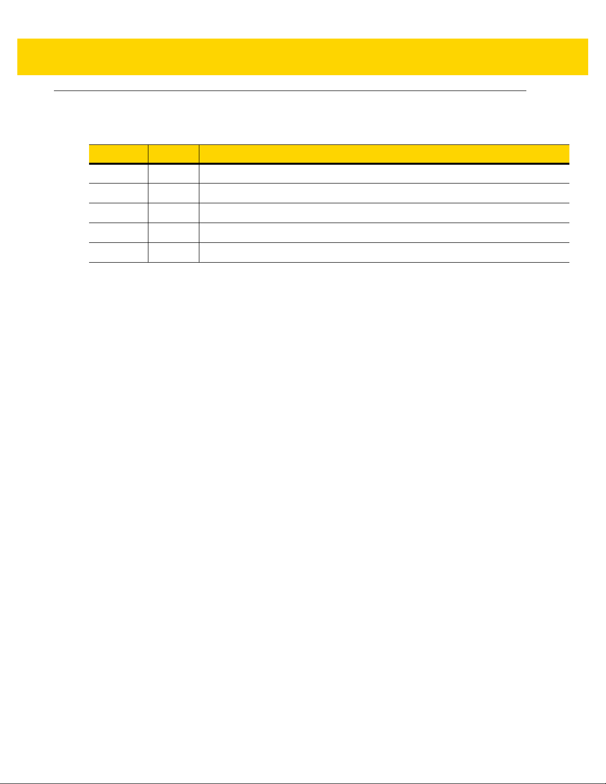
Revision History
Changes to the original guide are listed below:
Change Date Description
-01 Rev A 1/2016 Initial Release.
iii
Page 6

iv Deploying VoWLAN Over Aruba Networks Best Practices Guide
Page 7

TABLE OF CONTENTS
Revision History................................................................................................................................. iii
About This Guide
Introduction....................................................................................................................................... vii
Chapter Descriptions ........................................................................................................................ vii
Notational Conventions..................................................................................................................... vii
Related Documents ......................................................................................................................... viii
Service Information.......................................................................................................................... viii
Chapter 1: Introduction
Coverage ....................................................................................................................................... 1-1
QoS ................................................................................................................................................ 1-3
Security .......................................................................................................................................... 1-4
General Wireless Network Best Practices ..................................................................................... 1-5
Chapter 2: SSID Profile
Chapter 3: Virtual AP Profile
Chapter 4: RF Adaptive Radio Management Profile
Chapter 5: RF 802.11 Profile
Chapter 6: VoIP CAC Profile
Page 8

vi Deploying VoWLAN Over Aruba Networks Best Practices Guide
Page 9

ABOUT THIS GUIDE
Introduction
This guide provides best practices when dep l oying VoWLAN over a Aruba wireless network.
NOTE Screens and windows pictured in this guide are samples and can differ from actual screens.
Chapter Descriptions
Topics covered in this guide are as follows:
•
Chapter 1, Introduction provides information for deploying VOWLAN over a Aruba wireless network.
•
Chapter 2, SSID Profile provides information for setting up SSID profiles.
•
Chapter 3, Virtual AP Profile provides information for setting up Virtual AP profiles.
•
Chapter 4, RF Adaptive Radio Management Profile provides information for setting up RF Adaptive Radio
management profile.
•
Chapter 5, RF 802.11 Profile provides information for setting up RF 802.11profile.
•
Chapter 6, VoIP CAC Profile provides information for setting up VoIP CAC profile.
Notational Conventions
The following conventions are used in this document:
•
Italics are used to highlight the following:
• Chapters and sections in this and related documents
• Icons on a screen.
Page 10

viii Deploying VOWLAN Over Aruba Networks Best Practices Guide
•
Bold text is used to highlight the following:
• Dialog box, window, and screen names
• Drop-down list and list box names
• Check box and radio button names
• Key names on a keypad
• Button names on a screen.
•
Bullets (•) indicate:
• Action items
• Lists of alternatives
• Lists of required steps that are not necessarily sequential
•
Sequential lists (e.g., those that describe step-by-s te p pr oc ed ur e s) ap pe a r as nu m be re d lists.
Related Documents
•
Cisco CUCM Administrator Configuration Guide, p/n MN001147Axx
•
Cisco CME Technical Guide, p/n MN 00 1148Axx
For the latest version of this guide and all guides, go to: http://www.zebra.com/support
Service Information
If the user has a problem with the equipment, contact Global Customer Support in the region. Contact information
is available at: http://www.zebra.com/support
When contacting support, please have the following information available:
•
Serial number of the unit (found on manufacturing label)
•
Model number or product name (found on manufacturing label)
•
Software type and version number
We respond to calls by email or telephone within the time limits set forth in support agreements.
If the problem cannot be solved by Customer Support, the user may need to return the equipment for servicing and
will be given specific directions. We are not responsible for any damages incurred during shipment if the approved
shipping container is not used. Shipping the units improperly can possibly void the warranty.
If the device was purchased from a business partner, cont act that business partner for support.
.
.
Page 11

CHAPTER 1 INTRODUCTION
Voice over Wireless LAN (VoWLAN) delivers the functionality of an enterprise telephone system in a wireless
handset. The handset is a wireless client device, and it shares the wireless network with laptops and other
hand-held devices. For enterprise use, the handset is functionally equ ivalent to a wired desk phone, giving
end-users all the features they are used to in a wired office telephone. The benefits of VoWLAN can result in
substantial cost savings, leveraging Wi-Fi infrastructure and eliminating recurring charges associated with the use
of cell phones, while significantly improving employee mobility.
There are two types of mobility, being mobile and 100%-connected mobility. To help explain this, think of the
marketing manager working on a presentation and saving it on a network share. He later wants to give that
presentation in the boardroom. If he picks up his laptop, closes the lid, and walks to the boardroom, opens th e
laptop, connects to the wireless network, and gives his presentation - that is being mobile. His laptop may have
disconnected from the wireless network in between his office and the boardroom, but he never noticed. The same
manager starting a call on his VoWLAN handset while in his office, remaining on that call as he walked to the
elevator, traveled up several floors, and then walked to the boardroom – that is true mobility. If his VoWLAN
handset had disconnected during that call, he would have noticed.
True mobility and enterprise-grade VoWLAN requires wireless networks designed to provide the highest audio
quality throughout the facility . VoWLAN handsets require continuous, reliable connections as a user moves
throughout the coverage area. Voice applications have a low tolerance for network errors and delays, deteriorating
with just a few hundred milliseconds of delay or 1% of packet loss.
Coverage
Most data communication protocols provide a mechanism for retransmission of lost or corrupted packets, thus
delays caused by retransmissions are not disc er na b le. The real-time nature of a telephone conversation requires
that voice packets be received correctly within 100ms of transmission. Lost or corrupted packets are discarded
after limited retries. In areas of inadequate wireless coverage, the audio quality of real-time voice will suffer.
Moving handsets make the determination to roam in less than half the overlapping coverage area from a
neighboring access point. That Assessmen t Area mu st be larg e en o ugh to allow th e hand se t tim e to disco ve r,
associate with, and connect to the next access point before the signal on the currently connected access point
becomes too weak. Understanding what imp acts RF coverage, ce ll size, and overlap is essential to pr operly design
and configure a wireless network for voice usage.
The usable cell size of an access point is dictated by the frequency, signal power level, minimum data rate, number
of channels used, and objects that attenuate the signal. A properly designed wireless network positions access
points with sufficient overlapping co vera ge to ensur e there ar e no co ve ra ge gaps between them. 20% overlapping
Page 12

1 - 2 Deploying VoWLAN Over Aruba Networks Best Practices Guide
coverage between access points will result in seamless hand-offs and excellent voice quality at the average
walking speed of 3 mph. If the speed of the moving user is greater (golf cart, fork lift or running/jogging), a larger
overlap percentage may be necessary.
Dynamic Channel Assessment (DCA) is generally performed between the transmission of voice and control
packets to learn about neighboring access points. It takes approximately 250 ms to process each channel in the
channel list. To determine the size of access point Cell Overlap, determine the number of feet covered per second
for the average walking speed of 3mph:
•
5,280 feet per mile * 3mph = 15,840 feet per hour
•
15,840 feet per hour / 60 = 264 feet per minute
•
264 feet per minute / 60 = 4.4 feet per second
Then apply that distance to the duration of the DCA Cycle for each band/channel conf iguration. The Assessment
Area is approximately ¾ of the Coverage Overlap Area . Ov er lap Perce ntage is based on access points located 60
feet apart.
The following table shows the results of those calculation s for various channel configurations:
Band
2.4 GHz 3.00 250.00 0.75 3.30 4.40 7%
5 GHz 8.00 250.00 2.00 8.80 11.70 20%
5 GHz 12.00 250.00 3.00 13.20 17.60 29%
5 GHz 23.00 250.00 5.75 25.30 33.70 56%
Failure to complete the DCA cycle within the assessment area can lead to loss of connectivity, choppy audio, or a
dropped call. Give careful consideration to the number o f channels de ploye d in 5 GHz for a VoWLAN environment
to avoid this.
There are unique requirements for the various types of WLAN implementations. A data-only implementation does
not require significant cell overlap as 802.11 clients typically step down their rate to accommodate the transition to
another access point. Typical thresholds for a data-only implementation are a Signal Strength of -82 dBm and a
Signal-to-Noise Ratio (SNR) of 10 dB.
The voice-data implementation generally requires a Signal Strength of -65 dBm, a Signal-to-Noise Ratio (SNR) of
25 dB or better, and a Cell Overlap of 20%. The Cell Overlap ensures that a VoWLAN handset can detect and
connect to alternative access points before it reaches its current cell boundary. The Signal Strength target of -65
dBm at the cell edge results in more access points running at lower power levels. A same channel separation of 19
dB is necessary to diminish co-channel interference. In a voice-data implement ation , a low noise backgr ound is as
important as high energy density. Transient conditions will make themselves more evident in a voice-data
implementation. The actual target minimum Signal Strength depends on the 802.11 frequency band it is operating
in, modulation used, data rates enabled on the access point, and data rate used by the handset at any particular
time.
Number
Channels
Duration
(ms)
DCA Cycle
(seconds)
Assessment
Area
Coverage
Overlap
Overlap
percentage
Page 13

2.4 GHz 802.11b/n (CCK)
Rate (Mbps) 1 2 5.5 11
Introduction 1 - 3
Minimum Signal Strength
(dBm)
2.4 GHz 802.11g /n (OFDM)
Rate (Mbps) 6 9 12 18 24 36 48 54
Minimum Signal Strength
(dBm)
5 GHz 802.11a/n (OFDM)
Rate (Mbps) 6 9 12 18 24 36 48 54
Minimum Signal Strength
(dBm)
Dynamic Channel Assignment and Intelligent Transmit Power Control should be used in all V oWLAN deployment s.
Transmit Power Minimum and Maximum levels should be established based on the maximum transmit power of
the client used. In the case of multiple clients, minimum and maximum levels should be set to accommodate the
client with the weakest transmit power. It is essential to prevent the access point from transmitting at a higher
power than the client.
-75 -70 -68 -65
-67 -66 -64 -62 -60 -56 -52 -47
-67 -65 -63 -61 -58 -54 -52 -50
QoS
WMM is based on IEEE 802.11e Enhanced Distributed Coordination Access (EDCA). The first component of WMM
are the four Access Categories (derived from 802.1d).
Client wait time +
WMM Access Category Priority Level 802.1d tags
Voice (AC_VO) highest 7,6 2 + 0 to 3 Voice
Video (AC_VI) 5,4 2 + 0 to 7 Call control
Best Effort 0,3 3 + 0 to 15 Other (PTT, OAI,
Background (AC_BK) lowest 2,1 7 + 0 to 15 Not used
WMM relies on the application to assign the appropriate access category for the traffic it generates. Once the
application assigns each packet to an access category , p ackets are then ad ded to one of four independent tr ansmit
random backoff
window (slots)
SIP Traffic Type
RTLS)
Page 14

1 - 4 Deploying VoWLAN Over Aruba Networks Best Practices Guide
queues in the access point and client. Once transmitted onto the wireless network applications compete for
available bandwidth, resulting in packet collisions. When this happens the access category used will determine the
retransmission timing. The higher the priority level, the lower the required wait time and random “back-off” window.
WMM Power Save is the second component of WMM. Based on the IEEE 802.11e Unscheduled Automatic Power
Save Delivery (U-APSD) mechanism, it is an enhancement of the legacy 802.11 power save mechanism. The
application-based approach used in WMM Power Save enables individual applications to decide how often the
client needs to communicate with the access point and how long it can remain in a “rest ful” state. In addition, WMM
Power Save increases transmission efficiency by transmitting the same amount of data in a shorter time using
fewer frames. Power save behavior is negotiated during the associatio n of a handset with an access point
The third component of WMM, WMM Admission Control, allows the access point to manage its available “air time”
based on traffic requirements submitted by associated clients. Requests are rejected if insufficient resources are
available. Use of WMM Admission Control avoids over-subscribing the access point, preserving and protecting
QoS for all associated devices.
Security
Authentication is the process that occurs after WLAN association, where the handset and authentication server
verify each others credentials then allow the handset access to the network. WP A2 has two different authentication
modes, Personal and Enterprise. Personal mode uses a password-based authentication method called
Pre-Shared Key (PSK). Personal mode is good for time-sensitive applications such as voice, because the key
exchange sequence is limited and does not adversely affect roaming between access points. The PSK can be
entered in hexadecimal or as an ASCII passphrase from the handset’s administration menu or through
configuration files.
WPA2 Enterprise security mode requires a WLAN device to mutually validate credentials through 802.1X with a
RADIUS server on the network every time the device roams to a new access point. Authentication delays during
roaming may cause dropped packets and result in longer delays and audio artifacts. The size of the credentials
used and the location of the RADIUS authentication server can significan tly affe ct the duration of that delay. Larger
credentials are more secure, but they take more time to process.
Fast access point hand-off techniques allow for the part of the key derived from the authentication server to be
cached in the wireless network, thereby shortening the time to renegotiate a secure hand-off. Client handsets
generally offer two 802.1X authentication types (PEAPv0 with MSCHAPv2 or EAP-FA ST), and two fast access
point hand-off mechanisms (OKC or CCKM). The combination of the selected 802.1X authentication type and fast
access point hand-off mechanisms results in faster roaming and fewer audio artifacts. Use of the fast access point
hand-off methods does not eliminate situations where full 802.1X key exchanges must re-occur.
PEAP (Protected Extensible Authentication Protocol) was developed by Microsoft, Cisco and RSA Security for
802.1X authentication on WLANs. PEAPv0 with MSCHAPv2 is one of the most-commonly used PEAP subtypes.
PEAP makes use of a server-side public key certificate to authenticate the server and creates an encrypted tunnel
to exchange information between the server and the client. Larger certificate key size s provide stronger encryption,
but are more computationally intensive and therefore take more time to process. The longer processing time can
result in audio artifacts.
EAP-FAST (Extensible Authentication Protocol-Flexible Authentication via Secure Tunneling) was created by
Cisco as a replacement for LEAP (Lightweight Extensible Authentication Protocol). EAP-FAST has since gained
adoption by WLAN vendors besides Cisco and is growing in popularity. Rather than relying on certificates,
EAP-FAST use a Protected Access Credential (PAC) to establish a tunnel in which client credentials are verified.
Cisco Centralized Key Management (CCKM) is a Cisco-proprietary fast access point hand-off method supported
on Cisco access points. The combination of either PEAP/MSCHAPv2 or EAP-F AST with CCKM will result in faster
hand-offs once the initial 802.1X exchange has occurred. The faster hand-offs occur as the user roams within the
coverage area and the WLAN infrastructure retains authentication key information for the associated clients. The
Page 15

RADIUS server does not need to be reached at every access point hand off and the duration of the authentication
exchange is fast enough to maintain audio quality. When the handset loses access point connectivity and must
re-acquire its connection to the WLAN, a full 802.1X authentication with the RADIUS server is required during the
re-acquisition. During this period, audio artifacts may become apparent.
General Wireless Network Best Practices
In order for voice to operate efficiently in a wireless network, it is critical that it be separated from the data traffic by
using 802.1q VLANs.
Most access points can be configured to allow or deny association of wireless clients based on their unique MAC
address and is sometimes used as a method of securing the WLAN. This process is not recommended for a
VoWLAN environment. MAC filtering is ineffective as a security method.
The traffic filtering capabilities of firewalls, Ethernet switches, and wireless controllers can also be used as an
additional security layer when configured to allow only certain types of traffic to pass onto specific areas of the
LAN. To properly provide access control, it is necessary to understand the type of IP traffic used. Following is a
table of common port numbers:
Introduction 1 - 5
Protocol Type Port
FTP TCP 21
SSH TCP 22
Telnet TCP 23
DNS UDP 53
DHCP UDP 67
DHCP UDP 68
TFTP UDP 69
HTTP TCP 80
NTP UDP 123
LDAP Both 389
HTTPS TCP 443
Syslog UDP 514
LDAP over TLS Both 636
SIP Both 5060
SIP over TLS TCP 5061
While wireless handsets will generally work through a Firewall (if the appropriate ports are allowed) it is not
recommended. Firewalls create jitter which can severely limit the successful and on-time delivery of audio packets.
Page 16

1 - 6 Deploying VoWLAN Over Aruba Networks Best Practices Guide
Page 17

CHAPTER 2 SSID PROFILE
An SSID (Service Set Identifier) profile defines the name of the network, authentication type for the network, basic
rates, transmit rates, SSID cloaking, and certain WMM settings for the network. One particular feature configured
in the SSID Profile that can have a significant effect on VoIP over wireless is Maximum Transmit Failures.
Max-TX-Fail is a feature Aruba uses to address “sticky client” issues. Aruba controllers clean up non-responsive
clients by sending several de-authentication packets. If this occurs because the client has left the area or been
powered off it causes no issues. Unfortunately, when it occurs in the middle of a valid session, without any action
from the client, it causes many artifacts, including, but not limited to dropped calls, one-way audio, an d ring/no
answer. Setting
improves phone performance.
Verify or apply the following settings for each SSID Profile used to deliver VoIP over wireless.
Table 2-1 SSID Profile
max-tx-failures=0 usually eliminates the unanticipated de-authentica tio n is su e an d dr as tica lly
wlan ssid-profile
<profile-name>
Management Frame
Protection Capable
Management Frame
Protection Required
DTIM Interval Number of Beacon
Description Command Range/Default
MFP allowed
MFP required
Cycles between DTIMs.
mfp-capable
disabled
mfp-required
disabled
dtim-period 2
enabled, disabled /
disabled
enabled, disabled /
disabled
1 > / 1
Page 18

2 - 2 Deploying VoWLAN Over Aruba Networks Best Practices Guide
Table 2-1 SSID Profile (Continued)
wlan ssid-profile
<profile-name>
Data Rates (Basic and
Transmit / 802.11a and g)
Description Command Range/Default
Basic rates used for
management traffic 5GHz.
a-basic-rates
Setting depends on
c ov e ra g e a nd c li e nt t y p e
6, 12, 24 Mbps
recommend disabling
slower data rates to
improve overall
utilization.
Rates used for data 5GHz.
a-tx-rates
Setting depends on
6, 9, 12, 18, 24, 36, 48,
54 Mbps
coverage and channel
utilization
recommend disabling
slower data rates to
improve overall
utilization.
Basic rates used for
management traffic -
2.4GHz.
g-basic-rates
Settings depend on
c ov e ra g e a nd c li e nt t y p e
1, 2 Mbps
recommend disabling
slower data rates to
improve overall
utilization.
Rates used for data -
2.4GHz
Maximum Transmit
Attempts
Maximum Transmit
Failures
Maximum number of
retries
Number consecutive
frames not delivered after
which the AP assumes
the client has left and
should be
deauthenticated.
WMM Wireless Multimedia
traffic prioritization.
g-tx-rates
Setting depends on
coverage and channel
utilization
recommend disabling
slower data rates to
improve overall
utilization.
max-retries 4
max-tx-fail 0
Set to zero to prevent
unanticipated
deauthentications.
wmm enabled
1, 2, 5, 6, 9, 11, 12, 18,
24, 36, 48, 54
0-15 / 4
0-2,147, 483, 647 / 0
enabled, disabled /
disabled
Page 19

Table 2-1 SSID Profile (Continued)
SSID Profile 2 - 3
wlan ssid-profile
<profile-name>
WMM-UAPSD Unscheduled Automatic
Local Probe Request
Threshold
Description Command Range/Default
Power Save Delivery
SNR Threshold below
which incoming probe
requests will be ignored.
Setting to 0 to disable.
wmm-uapsd enabled
local-probe-req
thresh 0
Set to zero to prevent
ignored probe requests
causing voice artifacts.
enabled, disabled /
enabled
0-100 / 0
Page 20

2 - 4 Deploying VoWLAN Over Aruba Networks Best Practices Guide
Page 21

CHAPTER 3 VIRTUAL AP PROFILE
Configure virtual AP (Access Point) profiles to provide different network access or services to users on the same
physical network.
Verify or apply the following settings for each Virtual AP Profile used to deliver VoIP over wireless.
Table 3-1 Virtual AP Profile
wlan virtual-ap
<profile-name>
Band Steering E ncourage or require
Steering Mode Method used to do
Description Command Range / Defaults
dual-band clients to
stay on the 5 GHz
band.
band-steering.
Does not apply if
band-steering is
disabled.
band-steering
Disable unless voice SSID is
operated on both 2.4 GHz
and 5 GHz bands.
Recommend disabling to
allow the device to choose
the AP.
steering-mode
prefer-5GHz
Not applicable unless voice
SSID operated on both 2.4
GHz and 5 GHz bands, then
prefer-5 GHz
set to
.
enabled, disabled / disabled
force-5GHz, prefer-5GHz,
balance-bands
Page 22

3 - 2 Deploying VoWLAN Over Aruba Networks Best Practices Guide
Page 23

CHAPTER 4 RF ADAPTIVE RADIO
MANAGEMENT PROFILE
Aruba's Adaptive Radio Management (ARM) technology dynamically and intelligently chooses the best 802.11
channel and transmit power for each Aruba AP in its current RF environment. ARM dynamically monitors and
adjusts the network to ensure that all users are allowed ready access. One particular feature configured in the
ARM Profile that can have a significant effect on VoIP over wireless is Aggressive or Dynamic Scanning. The
Aggressive or Dynamic Scanning feature is unique to Aruba. It allows less-utilized APs to go off-channel to scan for
rogue APs and clients more often. The increased frequency of off-channel scanning will not occur if a data or voice
client is currently using the radio. The problem with this setting arises as the VoIP over wireless client needs to
roam to a less-utilized AP during a call. The AP could legitimately be off-channel scanning and not respond within
the time frame necessary to not produce an artifact of some kind. Since there is limited benefit to the additional
time spent off-channel scanning, it is safer to disable this feature if the wireless network must support VoIP.
Verify or apply the following settings for each Adaptive Radio Management Profile used in a VoIP over wireless
environment.
Table 4-1 RF Adaptive Radio Management Profile
rf arm-profile
<profile>
Aggressive
Scanning
Client Match optimize network
Client Aware
Scan
Description Command Range / Defaults
AP radios without
clients associated
will go off-channel to
scan every second.
resources by
balancing clients
across channels.
Prevent APs from
changing channels if
an active client is
associated.
aggressive-scan disabled
In a voice environment, enabling this setting
could result in a radio being off-channel
scanning when a voice client needs to roam
to it, causing a voice artifact.
client match disabled
In a voice environment, enabling this feature
could result in a voice client being
deauthenticated when roaming, causing a
voice artifact.
client-aware disabled
Enabling this feature could contribute to a
sub-optimum channel allocation.
enabled, disabled /
enabled
enabled, disabled /
enabled
enabled, disabled /
enabled
Page 24

4 - 2 Deploying VoWLAN Over Aruba Networks Best Practices Guide
Table 4-1 RF Adaptive Radio Management Profile (Continued)
rf arm-profile
<profile>
VoIP Aware
Scan
Power Save
Aware Scan
Maximum
Transmit
Power
Minimum
Transmit
Power
Description Command Range / Defaults
Prevents APs from
changing channels if
an active voice call is
in progress.
Prevents APs from
changing channels if
a client is in power
save mode.
Maximum transmit
power.
Minimum transmit
power.
voip-aware-scan enabled
In a voice environment, disabling this feature
could result in a voice client roaming to a
radio that is off-channel scanning.
ps-aware-scan enabled
In a voice environment, clients devices could
be in power-save mode regularly
max-tx-power
Setting depends on coverage and client type.
Adjust to the lowest possible setting which
produces adequate coverage and overlap.
min-tx-power
Setting depends on coverage and client type.
Adjust to ensure coverage where the signal
between APs are stronger than between AP
and client.
enabled, disabled /
disabled
enabled, disabled /
disabled
3, 6, 9, 12, 15, 18, 21,
24, 27, 30, 33, 127 /
127
3, 6, 9, 12, 15, 18, 21,
24, 27, 30, 33, 127 / 9
Page 25

CHAPTER 5 RF 802.11 PROFILE
The 802.11a and 802.11g RF management profiles for an AP configure its 5 GHz and 2.4 GHz radio settings.
Verify or apply the following settings for each RF 802.11 Profile used in a Vo IP over wireless environment. Also
verify or apply the following in the Regulatory-Domain-Profile used by the customer.
Remove 5 GHz channels 52 - 64 and channels 100 - 14 0 from the list of supported channels. These channels,
referred to as U-NII-2 and U-NII-2-Extended , ar e part of the 5 GH z ban d that is subject to 802 .11h Spectrum and
Transmit Power Management Exte nsions. One of those ex tensions, Dynamic Frequency Sele ction (DFS), ensures
that channels containing radar are avoided by the APs comprising the wireless network. Because the step s used to
change channel upon the detection of radar energy are so disruptive, it is a good practice to simply avoid those
channels. The remaining eight channels will provide more than enough distribution, plus have the side benefit of
requiring less time to process which results in faster roaming.
Table 5-1 802.11a Profiles
rf
dot11a-radio-
profile
<profile>
Description Command Range / Defaults
Beacon period time between
successive beacon
transmissions
Spectrum Load
Balancing
optimize network
resources by
balancing clients
across channels
beacon period 100
spectrum-load-balancing disabled
In a voice environment, enabling this feature
could result in a voice client being
deauthenticated when roaming, causing a
voice artifact.
60 - >
enabled, disabled /
disabled
Page 26

5 - 2 Deploying VoWLAN Over Aruba Networks Best Practices Guide
Table 5-2 AP Regulatory Domain Profiles
ap
regulatory-do
main-profile
<profile>
Description Command Range / Defaults
Valid 5 GHz
Channels
Valid 2.4 GHz
Channels
Specify a 5 GHz
channel to be used
by ARM.
Specify a 2.4 GHz
channel to be used
by ARM.
valid-11a-channel
Recommended channels are
36,40,44,48,149,153,157 and 161.
valid-11g-channel
Recommended channels are 1, 6 and 11.
36-48, 52-64,
100-140, 149-161,
165
1-11
Page 27

CHAPTER 6 VOIP CAC PROFILE
Verify that a VoIP CAC Profile is set up and enabled in a VoIP over wireless environment.
Table 6-1 VoIP CAC Profile
wlan
voip-cac-profile
<profile-name>
Description Command Range / Defaults
Call Admission
Control
Use VoIP Signaling and
Tspec messages to
perform call admission
control.
call-admission-control
enabled
Enabling could result in a call
being denied.
Disabling could result in a call
established with less than
desirable quality.
enabled, disabled /
disabled
Page 28

6 - 2 Deploying VoWLAN Over Aruba Networks Best Practices Guide
Page 29

Page 30

Zebra Technologies Corporation, Inc.
3 Overlook Point
Lincolnshire, IL 60069, U.S.A.
http://www.zebra.com
Zebra and the stylized Zebra head are trademarks of ZIH Corp., registered in many
jurisdictions worldwide. All other trademarks are the property of their respective owners.
© 2016 ZIH Corp and/or its affiliates. All rights reserved.
MN002151A01 Revision A - January 2016
 Loading...