

Page 1

MP7000
MN-002914-08EN
Scanner Scale
Integrator Guide
Page 2

Page 3

MP7000 SCANNER SCALE
INTEGRATOR GUIDE
MN-002914-08EN
Revision A
February 2021
Page 4

ii MP7000 Scanner Scale Integrator Guide
Revision History
Changes to the original guide are listed below:
Change Date Description
-08EN Rev. A February 2021 Updated "Identifying Firmware Version" instructions.
-07EN Rev. A December 2020 Removed reference of slave in Host Interfaces chapter.
-06EN Rev. A June 2020 Added:
- Color camera installation and specs
-05 Rev. A December 2019 Updated:
- Copyright statement
- Parameter #1246
- Table 2-8 (Terminal Specific Code ID Characters)
-04 Rev. A February 2018 Updated:
- Scale Pole Display Type parameters
-03 Rev. A August 2017 Updated Sensormatic information.
-02 Rev. A July 2017 Updates/Adds:
- Feedback URL
- MP7012 configurations
- MX101 PRG to Related Documents
- Changed 90 second timeout to 30 second timeout (scale calibration)
- Updated locations of AUX 1 & 2 ports
- Changed height of units above platter
- Horizontal Checkpoint Antenna parts
- Vertical Checkpoint Antenna parts
-01 Rev. A June 2017 Initial Release
Page 5

TABLE OF CONTENTS
Revision History ................................................................................................................................. ii
About This Guide
Introduction ........................................................................................................................................ v
Related Documents and Software ..................................................................................................... v
Chapter Descriptions ......................................................................................................................... v
Notational Conventions..................................................................................................................... vi
Zebra OneCare Support Services for the MP7000 ........................................................................... vii
Features for All Service Levels and All Products ........................................................................ vii
Global Support ...................................................................................................................... vii
Online Access to Software Updates...................................................................................... vii
Support Help Desk ................................................................................................................ vii
Comprehensive Coverage .................................................................................................... vii
Online RMA........................................................................................................................... vii
Additional Features for OneCare Select Service Only................................................................ vii
Advanced Exchange ............................................................................................................. vii
Spares Pool Management..................................................................................................... vii
24/7/365 Telephone Support................................................................................................ viii
Service Dashboard (Optional in Essential) .......................................................................... viii
On-site System Support.............................................................................................................. ix
Service Authorization .................................................................................................................. ix
Technical Support and Software.................................................................................................. x
Summary...................................................................................................................................... x
Chapter 1: Product Overview and Features
Introduction .................................................................................................................................... 1-1
Product Overview ........................................................................................................................... 1-2
Configurations ................................................................................................................................ 1-3
Peripherals ..................................................................................................................................... 1-8
Supported Auxiliary Hand-held Scanner .................................................................................. 1-8
EAS Devices ............................................................................................................................ 1-8
Scale Devices .......................................................................................................................... 1-8
Page 6

iv MP7000 Scanner Scale Integrator Guide
USB Flash Drives ..................................................................................................................... 1-8
Customer Side Scanner (CSS) ................................................................................................ 1-8
Related Product Line Configurations ............................................................................................. 1-8
Features of the MP7000 Scanner Scale ........................................................................................ 1-9
Scale Displays (Some Scanner/Scale Configurations Only) .................................................. 1-12
Flip Up Produce Bar (Standard on all Scale Models) ............................................................. 1-14
Features Summary ................................................................................................................. 1-14
Chapter 2: Host Interfaces and Cable Pinouts
Introduction .................................................................................................................................... 2-1
Interfaces, Components, and Communication ............................................................................... 2-1
POS Interfaces and Host Communication ............................................................................... 2-1
Auxiliary Ports and Peripherals ................................................................................................ 2-2
Programming Management Tools ............................................................................................ 2-2
Application Programming Interfaces ........................................................................................ 2-2
USB Interface ................................................................................................................................. 2-3
Connecting ............................................................................................................................... 2-3
USB Host Parameters .............................................................................................................. 2-4
USB Device Type ............................................................................................................... 2-4
RS-232 Interface .......................................................................................................................... 2-12
Connecting ............................................................................................................................. 2-12
MP7000 Scanner Only or MP7200/7500 Scale with Single Cable Protocol .................... 2-12
Price Computational Scale Interface Circuit Drawing ...................................................... 2-14
Connecting to an RS-232 Host ........................................................................................ 2-14
Models with a Dual Cable Scanner/Scale ........................................................................ 2-14
RS-232 Parameters ............................................................................................................... 2-16
RS-232 Host Parameters ....................................................................................................... 2-17
RS-232 Terminal Specific Parameters ............................................................................. 2-17
RS-232 Terminal Specific Code ID Characters ................................................................ 2-19
RS-232 Host Types ................................................................................................................ 2-21
RS-232 Host -NCR Variant .............................................................................................. 2-31
RS-232 Host -Datalogic Variant ....................................................................................... 2-32
RS-232 Device Port Configuration ......................................................................................... 2-33
Third Party Scale Parameters ................................................................................................ 2-46
Third Party Scale .............................................................................................................. 2-46
Third Party Scale LED Pin ............................................................................................... 2-48
Third Party Scale Zero Pin ............................................................................................... 2-50
IBM RS-485 Interface .................................................................................................................. 2-52
Connecting ............................................................................................................................. 2-52
IBM RS-485 Host Parameters ................................................................................................ 2-53
IBM Port Addresses ......................................................................................................... 2-54
IBM Port Addresses (continued) ...................................................................................... 2-57
IBM Scale Port Addresses ............................................................................................... 2-58
Connector Pins ............................................................................................................................ 2-62
RS-232 AUX 1 ........................................................................................................................ 2-62
Scale Display Port .................................................................................................................. 2-62
RS-232 AUX 2 ........................................................................................................................ 2-63
Checkpoint Interlock ............................................................................................................... 2-63
AUX A-B (Stacked USB) ........................................................................................................ 2-64
Page 7

Table of Contents v
POS ........................................................................................................................................ 2-64
12V DC ................................................................................................................................... 2-65
Chapter 3: Site Preparation and Installation
Introduction .................................................................................................................................... 3-1
Site Preparation ............................................................................................................................. 3-2
Ventilation and Spacing Requirements .................................................................................... 3-2
Service Access Requirements ................................................................................................. 3-2
Electrical Power Considerations .............................................................................................. 3-3
Grounding .......................................................................................................................... 3-3
Checkstand Preparation ........................................................................................................... 3-4
Liquid Spills and Moisture .................................................................................................. 3-4
Vertical Clearance .............................................................................................................. 3-4
Tools .................................................................................................................................. 3-4
Counter Cutout ................................................................................................................... 3-5
Ergonomics ........................................................................................................................ 3-5
Installing Components ................................................................................................................... 3-5
Quick Reference Installation Steps .......................................................................................... 3-5
Remove Existing Scanner Scale and Accessories .................................................................. 3-6
Unpacking MP7000 Scanner Scale Equipment ....................................................................... 3-6
Pre-Installation Notes ......................................................................................................... 3-7
Install the Scale Display ........................................................................................................... 3-8
Getting Started ................................................................................................................... 3-9
Installing ........................................................................................................................... 3-10
Cables and Connections ........................................................................................................ 3-10
Install the MX101 ................................................................................................................... 3-11
Install the MP7000 Scanner Scale ......................................................................................... 3-11
Checkstand Counter Cutouts and MP70XX Dimensions ................................................. 3-11
Cutout/Dimensions - MP70XX Short .......................................................................... 3-12
Cutout/Dimensions - MP70XX Medium ...................................................................... 3-14
Cutout/Dimensions - MP70XX Long ........................................................................... 3-16
Install the Sensormatic Coil Antenna ..................................................................................... 3-20
Install the Checkpoint Antennas ............................................................................................. 3-22
Horizontal Checkpoint Antenna ........................................................................................ 3-22
Vertical Checkpoint Antenna ............................................................................................ 3-23
Trim Kit Installation (If Required) ............................................................................................ 3-29
Chapter 4: Scale Calibration (For Models With a Scale)
Introduction .................................................................................................................................... 4-1
Scale Calibration Procedure (Scanner/Scale Configurations Only) ............................................... 4-2
Scale Configurations ................................................................................................................ 4-2
Step 1 - Electronic Entry into Calibration Mode ....................................................................... 4-3
Step 2 - Manual Entry into Calibration Mode ........................................................................... 4-3
Step 3 - Program Legal Parameters ........................................................................................ 4-4
Legal Scale Units (Unit Selection) - Kilograms or Pounds ................................................. 4-4
Important Notes ............................................................................................................ 4-4
Legal Scale Dampening Filter ............................................................................................ 4-5
Step 4 - Calibration at NO LOAD ............................................................................................. 4-5
Page 8

vi MP7000 Scanner Scale Integrator Guide
Step 5 - Calibration at LOAD .................................................................................................... 4-5
Step 6 - Calibration Success or Failure .................................................................................... 4-7
Calibration Success ........................................................................................................... 4-7
Calibration Failure .............................................................................................................. 4-8
Possible Reasons for a Fail .......................................................................................... 4-8
Calibration Mode Exit Conditions ............................................................................................. 4-8
Verification Test ....................................................................................................................... 4-8
Audit Tallies ............................................................................................................................ 4-12
Scale Configuration Parameters .................................................................................................. 4-13
Legal Scale Units ................................................................................................................... 4-13
Scale Display Configuration ................................................................................................... 4-15
Legal Scale Dampening Filter Setting .................................................................................... 4-17
Scale Pole Display Type ........................................................................................................ 4-21
User Interface Displays and Signals ............................................................................................ 4-23
Chapter 5: Operating the Scanner
Introduction .................................................................................................................................... 5-1
Controls and Indicators .................................................................................................................. 5-1
LED .......................................................................................................................................... 5-1
Diagnostic LED/7-segment Display .......................................................................................... 5-2
Front Panel Buttons ................................................................................................................. 5-3
Scale Zero Button (Configurations with Scale Only) .......................................................... 5-3
Volume/Tone Control Button .............................................................................................. 5-3
Sensormatic Manual Activation and Sensormatic Status Button ....................................... 5-4
Camera Activation Button .................................................................................................. 5-4
To Capture an Image ................................................................................................... 5-4
To Scan a Bank Check ................................................................................................. 5-4
Soft Reset Buttons ............................................................................................................. 5-4
Identifying Firmware Version .............................................................................................. 5-4
MP7000 Scanner Scale Related Hardware ................................................................................... 5-5
Scale Display (Scanner/Scale Configurations Only) ................................................................ 5-5
Scale (Scanner/Scale Configurations Only) ............................................................................. 5-5
Single Interval Range Scales ............................................................................................. 5-5
Dual Interval Range Scales ................................................................................................ 5-5
Calibration Switch .............................................................................................................. 5-5
CSS - Optional ......................................................................................................................... 5-5
Platter ....................................................................................................................................... 5-6
Removing the Short or Medium Platter .............................................................................. 5-6
Installing the Short or Medium Platter ................................................................................ 5-7
Removing the Long Platter ................................................................................................. 5-7
Installing the Long Platter ................................................................................................... 5-8
Scan Windows ......................................................................................................................... 5-8
Operating Modes ........................................................................................................................... 5-8
Programming the MP70XX ............................................................................................................ 5-9
Programming Management Tools ............................................................................................ 5-9
Application Programming Interfaces ........................................................................................ 5-9
Programming Barcodes ........................................................................................................... 5-9
USB Staging Flash Drive ............................................................................................................. 5-10
MP70XX Menu Structure for the USB Staging Flash Drive ................................................... 5-10
Page 9

Table of Contents vii
Manually Staging/Configuring MP70XX Devices ................................................................... 5-11
Loading Cloning Files ....................................................................................................... 5-12
123Scan Staging Flash Drive Configuration .......................................................................... 5-13
Approved USB Flash Drives for the Flash Drive Well ............................................................ 5-13
Scanning ...................................................................................................................................... 5-14
Weighing Items ............................................................................................................................ 5-14
Electronic Article Surveillance (EAS) ........................................................................................... 5-15
Supported EAS Controllers .................................................................................................... 5-15
EAS Operating Modes and Settings ...................................................................................... 5-16
Checkpoint Controller ............................................................................................................. 5-16
Sensormatic Controller ........................................................................................................... 5-17
Sensormatic EAS Hard Tags ................................................................................................. 5-17
Sensormatic EAS Soft Tags (Labels) ..................................................................................... 5-17
Beeper and LED Conditions ........................................................................................................ 5-18
Chapter 6: Color Camera Installation and Use
Introduction .................................................................................................................................... 6-1
Color Camera Kit ........................................................................................................................... 6-1
Kit Parts .................................................................................................................................... 6-2
Installing the Color Camera ........................................................................................................... 6-3
MP7000 Inner Housing ............................................................................................................ 6-3
Color Camera Uses ....................................................................................................................... 6-6
Chapter 7: 123Scan and Software Tools
Introduction .................................................................................................................................... 7-1
123Scan ......................................................................................................................................... 7-1
Communication with 123Scan .................................................................................................. 7-2
123Scan Requirements ............................................................................................................ 7-2
123Scan Information ................................................................................................................ 7-3
Scanner SDK, Other Software Tools, and Videos ................................................................... 7-3
Advanced Data Formatting (ADF) .................................................................................................. 7-4
Appendix A: Maintenance, Troubleshooting, and Error Codes
Introduction ................................................................................................................................... A-1
Maintenance ................................................................................................................................. A-1
Diagnostic LED 7-segment Display - Error and Warning Codes ............................................. A-2
LED Display Notes .................................................................................................................. A-2
Status Indicator Light .............................................................................................................. A-2
Troubleshooting Assistance .................................................................................................... A-3
General Error and Warning Codes .......................................................................................... A-4
Scale Warning Codes ............................................................................................................. A-6
Page 10

viii MP7000 Scanner Scale Integrator Guide
Appendix B: Technical Specifications
Appendix C: ASCII Character Sets
Appendix D: Standard Parameter Defaults
Appendix E: Communication Protocol Functionality
Functionality Supported via Communication (Cable) Interface ..................................................... E-1
Appendix F: Statistics
MP7 Statistics Definitions .............................................................................................................. F-1
Time and Usage ....................................................................................................................... F-1
Last Scanned Barcode ............................................................................................................. F-1
Decode Time and Count .......................................................................................................... F-1
Communication Diagnostics ..................................................................................................... F-3
Illumination Diagnostics ........................................................................................................... F-3
Sensor/Camera Diagnostics .................................................................................................... F-4
Scale Diagnostics ..................................................................................................................... F-5
EAS Diagnostics ...................................................................................................................... F-6
Object Detection Diagnostics ................................................................................................... F-6
Other Diagnostics ..................................................................................................................... F-6
Index
Page 11

ABOUT THIS GUIDE
Introduction
This guide provides information about installing, operating, and programming the MP7000 Scanner Scale.
NOTE
Screens and windows pictured in this guide are samples and can differ from actual screens.
Related Documents and Software
The documentation set for the device is divided into guides that provide information for specific user needs.
•
MP7000 Scanner Scale Barcode Programming Guide, p/n MN-002912-xx, provides barcodes for device
configuration.
•
MP7000 Scanner Scale Regulatory Guide, p/n MN-002939-xx, provides domestic and international
regulatory information.
•
MX101 Customer Side Scanner Product Reference Guide, p/n MN-003031-xx, provides barcodes for MX101
device configuration.
•
Advanced Data Formatting Programmer Guide, p/n 72E-69680-xx, provides information on ADF, a means of
customizing data before transmission to a host.
For the latest version of this guide and all guides, go to: www.zebra.com/support
Chapter Descriptions
Topics covered in this guide are as follows:
•
Chapter 1, Product Overview and Features provides an overview of the MP7000 Scanner Scale including
configurations, peripherals, and features.
•
Chapter 2, Host Interfaces and Cable Pinouts describes the host interfaces supported by the MP7000
Scanner Scale, how to connect to a host, setup, and cable pin-outs. It also includes host interface barcodes.
.
Page 12

vi MP7000 Scanner Scale Integrator Guide
•
Chapter 3, Site Preparation and Installation describes how to install the MP7000 Scanner Scale into a
counter top.
•
Chapter 4, Scale Calibration (For Models With a Scale) describes how to change weight measurement,
calibrate the scale, verify calibration, and recognize errors.
•
Chapter 5, Operating the Scanner describes how to operate the MP7000 Scanner Scale including buttons,
switches, LED indicators, and scanning.
•
Chapter 6, Color Camera Installation and Use describes how to install the color camera and it uses.
•
Chapter 7, 123Scan and Software Tools provides information about configuring the MP7000 Scanner Scale
using the 123Scan
•
Appendix A, Maintenance, Troubleshooting, and Error Codes provides error/warning codes, troubleshooting,
and maintenance information.
•
Appendix B, Technical Specifications provides technical information about the MP7000 Scanner Scale.
•
Appendix C, ASCII Character Sets provides ASCII character sets for some host interfaces.
•
Appendix D, Standard Parameter Defaults provides a list of defaults for the parameters in this guide. For all
MP7000 Scanner Scale programming barcodes, refer to the MP7000 Scanner Scale Barcode Programming
Guide (p/n MN-002912-xx).
utility.
•
Appendix E, Communication Protocol Functionality provides a table of MP7000 Scanner Scale
communication interfaces.
•
Appendix F, Statistics provides a table of MP7000 Scanner Scale attribute statistics.
Notational Conventions
The following conventions are used in this document:
•
Italics are used to highlight the following:
• Chapters and sections in this guide
• Related documents
•
Bold text is used to highlight the following:
• Dialog box, window and screen names
• Drop-down list and list box names
• Check box and radio button names
• Icons on a screen
• Key names on a keypad
• Button names on a screen.
•
Bullets (•) indicate:
• Action items
• Lists of alternatives
• Lists of required steps that are not necessarily sequential.
•
Sequential lists (e.g., those that describe step-by-step procedures) appear as numbered lists.
Page 13

Zebra OneCare Support Services for the MP7000
Zebra's Support Services include a complete portfolio of repair programs that offer an integrated support solution
that encompasses telephone support, software support, web self-service, and service center repair - all backed by
a global support infrastructure and proven expertise.
Zebra OneCare offers two levels of support on the MP7000 products; Zebra OneCare Essential and Zebra
OneCare Select. Each level provides different features and deliverables designed to meet customer requirements.
Features for All Service Levels and All Products
Global Support
With support for 16 languages and repair centers around the globe, we're ready to take care of your customers'
service needs, no matter where in the world they are located.
Online Access to Software Updates
All OneCare customers can download the updates as many times as desired via Zebra's 123Scan2 utility.
About This Guide vii
Support Help Desk
Zebra's help desk of technical professionals is open 24/7/365 to customers with select service contracts, Seamless
integration with Zebra's services helps ensure ongoing support for your customer's products. Our experienced
support engineers are available to assist customers with problem diagnosis and resolution - helping to ensure that
the systems they rely on to keep business critical functions running smoothly are available and running at peak
performance. Essential customers get coverage during business hours. Customers may log cases night and day especially useful to retailers and logistics companies whose doors never close - and whose workers continuously
utilize their Zebra products.
Comprehensive Coverage
Comprehensive Coverage. No matter what breaks, we fix it, no questions asked - from displays to housings.
Online RMA
Online RMA makes device return easier than ever. Customers can access the website to schedule a device return
any time of the day or night.
Additional Features for OneCare Select Service Only
Advanced Exchange
With Advanced Exchange, no matter what is wrong, when you or your customer reports a malfunctioning device,
we ship a replacement device the same day for next-business day replacement. The result? Minimal downtime for
malfunctioning devices, protecting productivity and return on investment.
Spares Pool Management
We maintain an inventory of the same devices your customer is utilizing. When a device requires a trip to the
service depot, we simply ship a replacement device from a pool to your customer. As devices are repaired, they are
returned to the pool.
Page 14

viii MP7000 Scanner Scale Integrator Guide
24/7/365 Telephone Support
After hours Level 1 support is always available for Zebra OneCare Select customers. Fully trained help desk
representatives with the skill set required to isolate, analyze and resolve issues will perform Level 1 Triage to
determine the best course of action. If help desk representatives are unable to resolve an issue, it is escalated to
Level 2 staff, who will respond during normal business hours. Partner value: If you are delivering the service, you
get the around-the-clock support you need to provide your customer with the best response times. Customer value:
Your customer gets the peace of mind that no matter when their device malfunctions, they can reach a technician.
Service Dashboard (Optional in Essential)
The Service Dashboard is a portal that provides visibility into the status of all devices in the repair cycle. With the
Select Dashboard, your customers can view the status of all open help desk cases; the condition of all their Zebra
devices at all sites, per site, per specific model; and the status of a specific individual device. Thresholds and date
ranges are customizable, allowing your customers to define what information is presented on the dashboard, such
as the number of resolutions completed. With both the Essential and Select dashboards, customers may track
repairs by serial number and the ratio of 'no trouble found' to repair resolutions. Customers can view the number of
devices, the number of devices due back to the depot and the number of devices currently received by the depot
and in repair. Select customers may check on the number of available spares in the pool. The Service Dashboard
is optional in the Essential service, standard in the Select service. Partner value: If your partners are delivering the
service, they can use the dashboard to reduce the time and cost associated with managing and monitoring devices
that are in the repair cycle. they can also offer their customers a version of the dashboard, complete with their own
logo, providing an extra value to your customer while promoting your brand. Customer value: Your customers can
heavily automate the management of devices in the repair cycle - no more time spent tracking devices and
preparing reports, driving down the cost of repair management.
Service Center support services are also available for customers who do not purchase service within 30 days of
purchasing the product. High level deliverables are shown below.
For customers not wishing to have hardware coverage and TTP partners (see below), Software Support Services
SWSS) are also available providing access to software releases and technical support.
A snapshot of the support services and part numbers are shown below.
Coverage Type Availability Coverage Description
Repair: Three
days from day of
Zebra OneCare Essential
with Comprehensive
Coverage
Zebra OneCare Select with
Comprehensive Coverage
Available up to 30
days from point of
sale.
Covers repair that is required
due to functional failure,
normal wear and tear, and
accidental damage. Includes
technical support, software
releases, and return
shipping. Services
Dashboard is also included
and the in Select (option in
Essential -
OPT-Dashboard-XX).
receipt in Zebra
repair center;
Technical Support
response four
Replacement
shipped on day of
Technical Support
response four
hours from
inquiry.
request;
hours from
inquiry.
# of Years
Covered
3 years
5 years
2 year renewal
3 years
5 years
2 year renewal
Page 15

About This Guide ix
Coverage Type Availability Coverage Description
Repair: Three
days from day or
receipt in Zebra
Service Center Essential
Service Center Select
Technical Support &
Software (TSS)
Any time up to
product End of Life.
Any time up to
product End of Life.
Covers repair that is required
due to functional failure, and
normal wear and tear.
Includes technical support,
device diagnostics, software
releases, and return
shipping.
Software and technical
support, and software
releases for MP7xxx
devices. Price is per device.
repair center;
Technical Support
response four
hours from
Replacement
shipped on day of
request;
Technical Support
response four
hours from
Technical Support
response: 4 hours
from inquiry.
inquiry.
inquiry.
# of Years
Covered
3 years
5 years
3 years
5 years
1 year
3 years
5 years
On-site System Support
Zebra's On Site System Support delivers peace of mind with the services your customers need, ensuring rapid
problem resolution and a fast return to full operable status with a range of options to fit their business needs. On
Site System Support is designed to provide an immediate response with minimum effort. Initiate on-site service
with a single phone call; a Zebra support specialist will offer quick problem determination and resolution. This is
only available in Certain Geographies check with your local services representative before offering.
Service Name Service Description Time Of Purchase
Service from the Start On-site
System Support
On-site System Support Any time One year
Fast response time: Field Service
Representative responds on site next
business day.
Includes Comprehensive Coverage.
Up front with the hardware
(prepaid) or within 30 days
thereafter.
Length Of
Coverage
Three years
Five years
Full access to technical support
resources.
Rights to download and use software
releases and supporting
documentation.
Service Authorization
Zebra has a service authorization program covering bioptic products, this allows qualified companies (such as
partners) to be trained and have access to spare parts allowing them to affect on-site repairs. This is a restricted
program and subject to strict entry criteria.
Within the retail environment it is well known that large retailers generally outsource maintenance and support for
all their POS equipment to one provider. When dealing with products such as the MP7000, these maintenance
providers have the necessary skills and tools to be able to repair units either in the field or at their own workshops
using Spare parts available under the Service Authorization program
Page 16

x MP7000 Scanner Scale Integrator Guide
Technical Support and Software
This service provides access to Zebra technical support resources during Business hours who will provide a 4 hour
response to problems raised. Additionally this service provides entitlement to access, deploy and use the latest
software releases for the MP7000 product.
Summary
The table below provides a summary of the standard support services available for the MP7000 products.
Zebra OneCare Essential Zebra OneCare Select
Term 3 or 5 Years 3 or 5 Years
Repair Turnaround Time 3 Business Days from Depot
Support Help Desk 8 x 5 24 x 7
Comprehensive Coverage
Buffer Stock Setup and Management N/A
Responsibility for Placing MP7000 Into
Trade
Overnight Shipping Option Option
Online Repair Services Dashboard Option Included
Receipt
Replacement Shipped on Day of Request
Purchaser Purchaser
On-site Support Limited Geographies
TSS
•
Fast response time. Field Services Representative responds on-site
next business day.
•
Include comprehensive coverage.
•
Full access to technical support resources.
•
Rights to download and use software releases and supporting
documentation.
•
Full access to technical support resources.
•
Rights to download and use software releases and supporting
documentation.
Page 17

CHAPTER 1 PRODUCT OVERVIEW
AND FEATURES
Introduction
This chapter includes the following topics:
• Product Overview on page 1-2
• Configurations on page 1-3
• Peripherals on page 1-8
• Features of the MP7000 Scanner Scale on page 1-9.
Page 18

1 - 2 MP7000 Scanner Scale Integrator Guide
Product Overview
The MP7000 Scanner Scale is a data capture solution that reads 1D, 2D and mobile barcodes in all orientations.
Barcode data is transmitted to a Point-Of-Sale (POS) host via USB, RS-232, or RS-485. Auxiliary device support
includes USB and RS-232 hand-held scanners, Checkpoint and Sensormatic Electronic Article Surveillance (EAS),
scale and optional Scale Display (varies with the model), USB staging flash drive (memory stick), as well as an
optional Customer Side Scanner (2D imager) that may be mounted into the tower. In addition the scanner has the
ability to read Digimarc barcodes.
The MP70XX is designed to be embedded in a cutout in the retail checkstand.
Features include:
• Reading 1D, 2D (PDF, Aztec etc.) and mobile barcodes (cell phone) in all orientations
• Reads top-bottom, left-right, and cashier-customer side barcodes
• Omni-directional symbol orientation.
• Optional integrated scale (single/dual interval).
• Optional Checkpoint EAS antenna.
• Support for low inductance Sensormatic EAS coil.
• Optional Scale Display (single/dual head) for scale installations.
• Auxiliary scanner support (USB and RS-232).
• High swipe speed for increased throughput.
• User interface (LED indicators, touch controls, audio).
• Aggressive scanning performance on high density, truncated, and poorly printed barcodes.
• Optional integrated Customer Side Scanner (CSS) - 1D/2D support.
• Scanner Management Service (SMS), and 123Scan support enables remote configuration and monitoring
attached peripherals.
Page 19

Configurations
The MP7000 Scanner Scale captures printed or mobile 1D or 2D barcodes. An optional customer-side scanner
(CSS) can be added for barcodes displayed on mobile phones, traditional loyalty cards, or item barcodes. \
Hand-held scanner, integrated EAS, and scale support is also available.
This guide covers the configurations listed in Table 1-1.
NOTE 1. All scale models include a flip up produce bar.
2. New scale configurations are added continually. If you don’t see your country listed, call your Zebra office.
Table 1-1 MP7000 Scanner Scale Configurations
Configuration Description
MP7000 Scanner Only
MP7000-SNS0M00WW MP7000 Scanner only, Short, Sapphire, WW
Product Overview and Features 1 - 3
MP7000-MNS0M00WW MP7000 Scanner only, Medium, Sapphire, WW
MP7000-LNS0M00WW MP7000 Scanner only, Long, Sapphire, WW
MP7000-SPS0M00WW MP7000 Scanner only, Short, Sapphire, Drivers License Parsing, WW
MP7000-MPS0M00WW MP7000 Scanner only, Medium, Sapphire, Drivers License Parsing, WW
MP7000-LPS0M00WW MP7000 Scanner only, Long, Sapphire, Drivers License Parsing, WW
MP7000 Scanner Scale
MP7001-LNSLM00US MP7001 Scanner Scale, Long, Single Interval Scale, Sapphire, United States
MP7001-LPSLM00US MP7001 Scanner Scale, Long, Single Interval Scale, Sapphire, Drivers License
Parsing, United States
MP7001-LNSLM00CM MP7001 Scanner Scale, Long, Single Interval Scale, Sapphire, Canada/Mexico
MP7001-LNSLM00EU MP7001 Scanner Scale, Long, Single Interval Scale, Sapphire, Europe
MP7001-LNSLM00AU MP7001 Scanner Scale, Long, Single Interval Scale, Sapphire, Australia
MP7001-LNSLM00NN MP7001 Scanner Scale, Long, Single Interval Scale, Sapphire, OIML
MP7001-LNSLM00CN MP7001 Scanner Scale, Long, Single Interval Scale, Sapphire, China
Notes:
1. EU scales are legally accepted in the following countries: Austria, Belgium, Bulgaria, Croatia, Cyprus, Czech
Republic, Denmark, Estonia, Finland, France, Germany, Greece, Hungary, Ireland, Iceland, Italy,
Liechtenstein, Lithuania, Luxembourg, Latvia, Malta, Netherlands, Norway, Poland, Portugal, Romania,
Slovak Republic, Slovenia, Spain, Sweden, Switzerland, and United Kingdom
2. OIML scales are legally accepted in the following countries: Bahamas, Barbados, Belize, Bermuda, Chile,
Colombia, Costa Rica, Ecuador, El Salvador, Guatemala, Hong Kong, Jamaica, Saint Lucia, Panama, Peru,
Philippines, Thailand, Trinidad, and Tobago
3. The color camera configuration type (portrait or landscape) is noted by the fifth digit after the dash. For
example, MP7001-MNSLX00EU includes a P (Portrait camera orientation) or C (Landscape camera
orientation).
Page 20

1 - 4 MP7000 Scanner Scale Integrator Guide
Table 1-1 MP7000 Scanner Scale Configurations (Continued)
Configuration Description
MP7001-LNSLM00RU MP7001 Scanner Scale, Long, Single Interval Scale, Sapphire, Russia
MP7001-LNSLM00DO MP7001 Scanner Scale, Long, Single Interval Scale, Sapphire, Dominican
Republic
MP7001-MNSLM00US MP7001 Scanner Scale, Medium, Single Interval Scale, Sapphire, United States
MP7001-MPSLM00US MP7001 Scanner Scale, Medium, Single Interval Scale, Sapphire, Drivers License
Parsing, United States
MP7001-MNSLM00CM MP7001 Scanner Scale, Medium, Single Interval Scale, Sapphire, Canada/Mexico
MP7001-MNSLM00EU MP7001 Scanner Scale, Medium, Single Interval Scale, Sapphire, Europe
MP7001-MNSLM00AU MP7001 Scanner Scale, Medium, Single Interval Scale, Sapphire, Australia
MP7001-MNSLM00NN MP7001 Scanner Scale, Medium, Single Interval Scale, Sapphire, OIML
MP7001-MNSLM00CN MP7001 Scanner Scale, Medium, Single Interval Scale, Sapphire, China
MP7001-MNSLM00RU MP7001 Scanner Scale, Medium, Single Interval Scale, Sapphire, Russia
MP7001-MNSLM00DO MP7001 Scanner Scale, Medium, Single Interval Scale, Sapphire, Dominican
Republic
MP7002-LNSLM00EU MP7002 Scanner Scale, Long, Dual Interval Scale, Sapphire, Europe
MP7002-LNSLM00AU MP7002 Scanner Scale, Long, Dual Interval Scale, Sapphire, Australia
MP7002-LNSLM00NN MP7002 Scanner Scale, Long, Dual Interval Scale, Sapphire, OIML
MP7002-MNSLM00EU MP7002 Scanner Scale, Medium, Dual Interval Scale, Sapphire, Europe
MP7002-MNSLM00AU MP7002 Scanner Scale, Medium, Dual Interval Scale, Sapphire, Australia
MP7002-MNSLM00NN MP7002 Scanner Scale, Medium, Dual Interval Scale, Sapphire, OIML
MP7000 Scanner Only with CSS
MP7010-LNS0M00WW MP7010 Scanner, Long, Sapphire, CSS, Worldwide
MP7010-LPS0M00WW MP7010 Scanner, Long, Sapphire, CSS, Drivers License Parsing, United States
MP7010-MNS0M00WW MP7010 Scanner, Medium, Sapphire, CSS, Worldwide
Notes:
1. EU scales are legally accepted in the following countries: Austria, Belgium, Bulgaria, Croatia, Cyprus, Czech
Republic, Denmark, Estonia, Finland, France, Germany, Greece, Hungary, Ireland, Iceland, Italy,
Liechtenstein, Lithuania, Luxembourg, Latvia, Malta, Netherlands, Norway, Poland, Portugal, Romania,
Slovak Republic, Slovenia, Spain, Sweden, Switzerland, and United Kingdom
2. OIML scales are legally accepted in the following countries: Bahamas, Barbados, Belize, Bermuda, Chile,
Colombia, Costa Rica, Ecuador, El Salvador, Guatemala, Hong Kong, Jamaica, Saint Lucia, Panama, Peru,
Philippines, Thailand, Trinidad, and Tobago
3. The color camera configuration type (portrait or landscape) is noted by the fifth digit after the dash. For
example, MP7001-MNSLX00EU includes a P (Portrait camera orientation) or C (Landscape camera
orientation).
Page 21

Product Overview and Features 1 - 5
Table 1-1 MP7000 Scanner Scale Configurations (Continued)
Configuration Description
MP7010-MPS0M00WW MP7010 Scanner, Medium, Sapphire, CSS, Drivers License Parsing, United
States
MP7010-SNS0M00WW MP7010 Scanner, Short, Sapphire, CSS, Worldwide
MP7010-SPS0M00WW MP7010 Scanner, Short, Sapphire, CSS, Drivers License Parsing, Worldwide
MP7010-MNSLM00WW MP7010 Scanner, Medium, Flip Bar Platter, CSS, Third Party Scale Support,
United States
MP7000 Scanner Scale with CSS
MP7011-LNS0M00US MP7011 Scanner Scale, Long, Single Interval Scale, Sapphire, CSS, Platter
without Flip Up Bar, United States
MP7011-LNSLM00AU MP7011 Scanner Scale, Long, Single Interval Scale, Sapphire, Platter with Flip Up
Bar, CSS, Australia
MP7011-LNSLM00CM MP7011 Scanner Scale, Long, Single Interval Scale, Sapphire, Platter with Flip Up
Bar, Canada/Mexico
MP7011-LNSLM00US MP7011 Scanner Scale, Long, Single Interval Scale, Sapphire, CSS, Platter with
Flip Up Bar, United States
MP7011-LPSLM00US MP7011 Scanner Scale, Long, Single Interval Scale, Sapphire, CSS, Drivers
License Parsing, Platter with Flip Up Bar, United States
MP7011-LNSLM00NN MP7011 Scanner Scale, Long, Single Interval Scale, Sapphire, CSS, Platter with
Flip Up Bar, OIML
MP7011-MNSLM00AU MP7011 Scanner Scale, Medium, Single Interval Scale, Sapphire, CSS, Platter
with Flip Up Bar, Australia
MP7011-MNSLM00EU MP7011 Scanner Scale, Medium, Single Interval Scale, Sapphire, CSS, Platter
with Flip Up Bar, Europe
MP7011-MNSLM00US MP7011 Scanner Scale, Medium, Single Interval Scale, Sapphire, CSS, Platter
with Flip Up Bar, United States
MP7011-MPSLM00US MP7011 Scanner Scale, Medium, Single Interval Scale, Sapphire, CSS, Platter
with Flip Up Bar, Drivers License Parsing, United States
MP7012-LNSLM00EU MP7012 Scanner Scale, Long, Dual Interval, Sapphire, CSS, Europe
Notes:
1. EU scales are legally accepted in the following countries: Austria, Belgium, Bulgaria, Croatia, Cyprus, Czech
Republic, Denmark, Estonia, Finland, France, Germany, Greece, Hungary, Ireland, Iceland, Italy,
Liechtenstein, Lithuania, Luxembourg, Latvia, Malta, Netherlands, Norway, Poland, Portugal, Romania,
Slovak Republic, Slovenia, Spain, Sweden, Switzerland, and United Kingdom
2. OIML scales are legally accepted in the following countries: Bahamas, Barbados, Belize, Bermuda, Chile,
Colombia, Costa Rica, Ecuador, El Salvador, Guatemala, Hong Kong, Jamaica, Saint Lucia, Panama, Peru,
Philippines, Thailand, Trinidad, and Tobago
3. The color camera configuration type (portrait or landscape) is noted by the fifth digit after the dash. For
example, MP7001-MNSLX00EU includes a P (Portrait camera orientation) or C (Landscape camera
orientation).
Page 22

1 - 6 MP7000 Scanner Scale Integrator Guide
Table 1-1 MP7000 Scanner Scale Configurations (Continued)
Configuration Description
MP7012-MNSLM00EU MP7012 Scanner Scale, Medium, Dual Interval, Sapphire, CSS, Europe
MP7012-LNSLM00NN MP7012 Scanner Scale, Long, Dual Interval, Sapphire, CSS, OIML
MP7012-MNSLM00NN MP7012 Scanner Scale, Medium, Dual Interval, Sapphire, CSS, OIML
MP7012-LNSLM00RU MP7012 Scanner Scale, Long, Dual Interval, Sapphire, CSS, Russia
MP7012-MNSLM00RU MP7012 Scanner Scale, Medium, Dual Interval, Calibration Switch, Sapphire,
CSS, Russia
MP7000 Scanner Scale with Color Camera
MP7001-MNSLP00EU Multiplane Scanner, Medium, Single Interval Scale, Color Camera Module Portrait,
Sapphire Glass, Europe
MP7001-MNSLP00AU Multiplane Scanner, Medium, Single Interval Scale, Color Camera Module Portrait,
Sapphire Glass, Australia
MP7001-MNSLC00US Multiplane Scanner, Medium, Single Interval Scale, Color Camera Module
Landscape, Sapphire Glass, United States
MP7001-MNSLC00EU Multiplane Scanner, Medium, Single Interval Scale, Color Camera Module
Landscape, Sapphire Glass, Europe
MP7001-LNSLP00NN Scanner, Single Interval Scale, Long, Color Camera Portrait, Sapphire, OIML
MP7001-LNSLP00CM Multiplane Scanner, Long, Single Interval Scale, Color Camera Module Portrait,
Sapphire Glass, Canada/Mexico
MP7001-LNSLC00NN Scanner, Single Interval Scale, Long, Color Camera Landscape, Sapphire, OIML
MP7001-LNSLC00CM Multiplane Scanner, Long, Single Interval Scale, Color Camera Module
Landscape, Sapphire Glass, Canada/Mexico
MP7001-LNS0P00US Multiplane Scanner, Long, Single Interval Scale, Color Camera Module Portrait,
Sapphire Glass, United States
MP7001-LNS0P00AU Multiplane Scanner, Long, Single Interval Scale, Color Camera Module Portrait,
Sapphire Glass, Australia
MP7001-LNS0C00US Multiplane Scanner, Long, Single Interval Scale, Color Camera Module
Landscape, Sapphire Glass, United States
Notes:
1. EU scales are legally accepted in the following countries: Austria, Belgium, Bulgaria, Croatia, Cyprus, Czech
Republic, Denmark, Estonia, Finland, France, Germany, Greece, Hungary, Ireland, Iceland, Italy,
Liechtenstein, Lithuania, Luxembourg, Latvia, Malta, Netherlands, Norway, Poland, Portugal, Romania,
Slovak Republic, Slovenia, Spain, Sweden, Switzerland, and United Kingdom
2. OIML scales are legally accepted in the following countries: Bahamas, Barbados, Belize, Bermuda, Chile,
Colombia, Costa Rica, Ecuador, El Salvador, Guatemala, Hong Kong, Jamaica, Saint Lucia, Panama, Peru,
Philippines, Thailand, Trinidad, and Tobago
3. The color camera configuration type (portrait or landscape) is noted by the fifth digit after the dash. For
example, MP7001-MNSLX00EU includes a P (Portrait camera orientation) or C (Landscape camera
orientation).
Page 23

Product Overview and Features 1 - 7
Table 1-1 MP7000 Scanner Scale Configurations (Continued)
Configuration Description
MP7001-LNS0C00AU Multiplane Scanner, Long, Single Interval Scale, Color Camera Module
Landscape, Sapphire Glass, Australia
MP7001-LND0P00US Scanner, Single Interval Scale, Long, Color Camera Portrait, Non-sapphire, United
States
MP7001-LND0C00US Scanner, Single Interval Scale, Long, Color Camera Landscape, Non-sapphire,
United States
MP7000-SNS0C00WW Multiplane Scanner, Short, Color Camera Module Landscape, Sapphire Glass,
Worldwide
MP7000-MNSLP00WW Multiplane Scanner, Long, Sapphire Glass, Scale Ready Platter, Third party scale
support, Color Camera Module Portrait,Worldwide
MP7000-MNSLC00WW Multiplane Scanner, Long, Sapphire Glass, Scale Ready Platter, Third party scale
support, Color Camera Module Landscape, Worldwide
MP7000-MNSDC00WW Multiplane Scanner, Long, Sapphire Glass, Scanner only/Scale Ready Platter,
Third party scale support, Color Camera Module Landscape, Worldwide
MP7000-MNS0C00WW Multiplane Scanner, Medium, Color Camera Module Landscape, Sapphire Glass,
Worldwide
MP7000-LNS0P00WW Long Scanner, Sapphire, Color Camera Portrait, Worldwide
MP7000-LNS0C00WW Multiplane Scanner, Long, Color Camera Module Landscape, Sapphire Glass,
Worldwide
MP7000-LCS0C00IN Long Scanner Scale With Single Interval Scale, Sapphire,calibration Switch,color
Camera, India
Notes:
1. EU scales are legally accepted in the following countries: Austria, Belgium, Bulgaria, Croatia, Cyprus, Czech
Republic, Denmark, Estonia, Finland, France, Germany, Greece, Hungary, Ireland, Iceland, Italy,
Liechtenstein, Lithuania, Luxembourg, Latvia, Malta, Netherlands, Norway, Poland, Portugal, Romania,
Slovak Republic, Slovenia, Spain, Sweden, Switzerland, and United Kingdom
2. OIML scales are legally accepted in the following countries: Bahamas, Barbados, Belize, Bermuda, Chile,
Colombia, Costa Rica, Ecuador, El Salvador, Guatemala, Hong Kong, Jamaica, Saint Lucia, Panama, Peru,
Philippines, Thailand, Trinidad, and Tobago
3. The color camera configuration type (portrait or landscape) is noted by the fifth digit after the dash. For
example, MP7001-MNSLX00EU includes a P (Portrait camera orientation) or C (Landscape camera
orientation).
Page 24

1 - 8 MP7000 Scanner Scale Integrator Guide
Peripherals
The MP7000 Scanner Scale supports the peripheral devices listed below.
Supported Auxiliary Hand-held Scanner
The MP70XX provides auxiliary data ports (USB and RS-232) to which a hand-held scanner can be connected.
NOTE An auxiliary cordless scanner, such as the DS2208, DS4308, or DS8178, can be attached to the MP70XX. If a
standard cradle is used with any of these scanners, a separate cradle power supply is required.
IMPORTANT The MP70XX scanner does not configure an auxiliary scanner. Auxiliary scanners must be configured
separately, independently of the MP70XX scanner.
EAS Devices
• Sensormatic AMB-9010 controller
• Sensormatic AMB-9010-IPS controller
• Checkpoint controller
• Checkpoint with interlock controller.
See Electronic Article Surveillance (EAS) on page 5-15 for detailed information.
Scale Devices
• OEM standard scale
• Single/dual head Scale Displays.
• Mettler-Toledo price computing scale for parts of Europe (available September 2017).
USB Flash Drives
• Typical USB flash drive with Type A connector. (See USB Staging Flash Drive on page 5-10.)
Customer Side Scanner (CSS)
• The CSS (MX101) is an optional integrated device that supports 1D and 2D barcode scanning. The CSS unit
replaces the MP70XX tower cover, and can be installed on either side of the MP70XX.
Related Product Line Configurations
Check Solution Builder for additional information regarding all available accessories, and the latest available
configurations.
Page 25

Features of the MP7000 Scanner Scale
The following illustrations of the medium model show the features of the MP70XX. See Table 1-2 on page 1-14 for
brief descriptions of all features. See Controls and Indicators on page 5-1 for detailed descriptions of each feature.
Vertical Scan Window
Product Overview and Features 1 - 9
LED
Speaker
Platter
Horizontal
Scan
Window
Figure 1-1 MP70XX Front View
Scale Zero Button
Volume/Tone Control Button
EAS Deactivation Button (Sensormatic only)
Color Camera Connection LED
Camera Activation Button
7-segment Diagnostic Display
(visible on both sides)
Scale (optional)
Page 26

1 - 10 MP7000 Scanner Scale Integrator Guide
Tower
Cover
EAS Cable Channel
(also see page 3-21 for
Sensormatic coil routing)
Drainage/Ventilation Holes
Figure 1-2 Left Side View
Drainage/Ventilation Holes
1
Checkpoint Interlock Port
2
Auxiliary USB Ports
0.0
Scale Display
Figure 1-3 Right Side View/Connector Ports
RS-232
AUX 2
I-LOCK
RS-232
1
AUX 1
AUX A-B
2
POS
12V DC
Page 27

Staging USB Flash
Drive Port Cover
Product Overview and Features 1 - 11
USB Port
Optional Scale
(Scale is not available in short
models)
Figure 1-4 View Under Platter
Page 28

1 - 12 MP7000 Scanner Scale Integrator Guide
290°
NOTE
Leveling screws accessory kit
MX301-SR00004ZZWR is
shipped with every short and
medium model.
Longer leveling screws with a
1 in. (25 mm) extra length are
available for purchase, if
required (accessory kit p/n
MX302-SR00004ZZWR).
Figure 1-5 Leveling Screws
Scale Displays (Some Scanner/Scale Configurations Only)
Figure 1-6 Single Head Scale Display
NOTE The MX201-SI00WW supports the single interval scale - lbs and kg; the MX201-DI00WW supports the
dual interval scale - lbs and kg.
Page 29

290°
290°
Product Overview and Features 1 - 13
Figure 1-7 Dual Head Scale Display
NOTE The MX202-SI00WW supports the single interval scale - lbs and kg; the MX202-DI00WW supports the
dual interval scale - lbs and kg.
Page 30

1 - 14 MP7000 Scanner Scale Integrator Guide
Flip Up Produce Bar (Standard on all Scale Models)
The Flip Up Produce Bar is used to help weigh very long or round items. This helps prevent the items from falling
off the scale and ensures accurate weighing.
Flip Up Produce Bar (lift if flat)
Figure 1-8 MP70XX with Optional Leek Platter
Features Summary
Table 1-2 Features on the MP7000 Scanner Scale
Feature Description Page
Diagnostic LED/7-segment Display
LED Provides visual feedback for system statuses and
Scale Zero Button Scale status LED and touch button provides
Volume/Tone Control Button
EAS Deactivation Button (Sensormatic
only)
Internal display provides detailed status,
troubleshooting information, and scale legal
parameters during calibration.
alerts.
scale status, and allows user to zero the scale.
User selectable settings for audible system
indications. (Status LED and button.)
Indicates the state of the Sensormatic EAS
device, and controls manual deactivation
(optional).
5-2
5-1
5-3
5-3
5-4
Page 31

Table 1-2 Features on the MP7000 Scanner Scale (Continued)
Feature Description Page
Product Overview and Features 1 - 15
Color Camera Connection LED When green, verifies that the MP7000 color
camera is on. Disconnecting/connecting the
MXC7000 USB cable causes the device to beep
and toggle the LED (up to a 10 second delay).
Camera Activation Button Allows a customer to take a picture. 5-4
Scale (Optional/ Scanner Scale
Configurations Only)
Platter Stainless steel horizontal scanning surface;
Calibration Switch Used in manual scale calibration. n/a
CSS (Optional) Modular unit that fits into the MP70XX tower;
Scale Display Single or dual display option provides the weight
Leveling Screws (medium and short
models only)
Scales are available for the medium length and
long length configurations.
imaging window for processing barcode data,
and placing items on the surface to determine
weight.
used for customer scanning.
of items on the scale.
Standard length leveling screws ship with all
short and medium models.
Longer length screws are available as an
accessory.
See Chapter 6,
Color Camera
Installation and
Use for color
camera details.
5-5
5-6
3-11
5-5
1-12
Connectors Connect the MP70XX to peripherals, and
POS/host.
Internal USB Cap/Port The internal USB port is available under the
platter.
EAS Cable Channel Cable routing channel for EAS antenna. 1-10
Scale Cable Channel Cable routing channel for the scale cable. 1-10
Drainage/Ventilation Holes Outlet for spills. 1-10
Table 1-3 Description of Connectors
Port Description
RS-232 AUX 2 (J7) See Table 2-3 on page 2-13 for description.
0.0 (J6) Scale Display port.
RS-232 AUX 1 (J5) See Table 2-3 on page 2-13 for description.
CKP I-LOCK (J4) Checkpoint EAS Interlock.
Table 1-3
1-12
Page 32

1 - 16 MP7000 Scanner Scale Integrator Guide
Table 1-3 Description of Connectors
Port Description
AUX A-B (J3) Dual USB 2.0 full speed ports for auxiliary USB scanners, CSS, or mass
storage device.
NOTE An additional USB port is available in the front under the platter. All USB ports
can be used for the USB staging flash drive. See Table 2-15 on page 2-64 and
USB Staging Flash Drive on page 5-10 for more information.
POS (J2) Point of Sale terminal port.
12V DC (J1) External power input. 12V / 3.33A (not required if powered from terminal).
NOTE If a power supply plug is inserted to the J1 connector, with no voltage to the
power supply, the scanner will not power up.
Page 33

CHAPTER 2 HOST INTERFACES AND
CABLE PINOUTS
Introduction
This chapter describes the host interfaces supported by the MP7000 Scanner Scale, and how to connect the
MP70XX to a host. It also include host interface barcodes. See Figure 1-1 on page 1-9 for locations of the interface
connectors.
OPOS/JAVAPOS settings are outside the scope of this guide. For the Zebra SDK, go to:
www.zebra.com/scannersdkforwindows.
NOTE SDK supported functionality by communication protocol is listed in Appendix E, Communication Protocol
Functionality.
Interfaces, Components, and Communication
The MP70XX supports the following.
POS Interfaces and Host Communication
IMPORTANTAvoid inserting a POS cable in the AUX 1 or AUX 2 port.
• USB 2.0 full speed using Zebra USB multi-host cables
• RS-232 connection using several communication protocols.
• RS-485 communication protocol.
NOTE SDK supported functionality by communication protocol is listed in Appendix E, Communication Protocol
Functionality.
Page 34

2 - 2 MP7000 Scanner Scale Integrator Guide
Auxiliary Ports and Peripherals
• Three USB 2.0 full speed auxiliary ports (see AUX A-B (Stacked USB) on page 2-64).
• Two RS-232 auxiliary ports (AUX 1/AUX 2; see Figure 1-3 on page 1-10).
The MP70XX can support the following combinations of peripherals:
• Hand-held scanners supported in USB mode, or RS-232 mode.
• CSS (CSS is USB only).
NOTE A total of one hand-held scanner plus one CSS is supported.
• Wireless auxiliary scanner support may be provided via a corded cradle as an auxiliary device.
NOTE An auxiliary cordless scanner, such as the DS2208, DS4308, or DS8178, can be attached to the MP70XX. If a
standard cradle is used with any of these scanners, a separate cradle power supply is required.
• Sensormatic controller via the RS-232 auxiliary port.
IMPORTANTUse only Zebra approved cables when connecting peripherals to the ports on the MP70XX.
• Dual cable scanner/scale: Via RS-232 AUX 1, or RS-232 AUX 2 ports (see Figure 1-3 on page 1-10, and
Table 2-3 on page 2-13).
Programming Management Tools
• 123Scan (see Chapter 7, 123Scan and Software Tools)
• SMS
• Staging flash drive reprogramming (USB memory stick).
NOTE Only Zebra hand-held scanners can be managed via 123Scan (see Chapter 7, 123Scan and Software
Tools), and SMS through the MP70XX scanner.
Application Programming Interfaces
• Zebra scanner SDK APIs (CoreScanner APIs).
NOTE SDK supported functionality by communication protocol is listed in Appendix E, Communication Protocol
Functionality.
• Zebra scanner OPOS/JPOS APIs.
For access to these programming interfaces, go to: www.zebra.com/scannersdkforwindows.
NOTE If the MP70XX is powered up with no interface cable present, it reverts to “no host mode.” This is useful for
demonstrations where no host is present.
Page 35

USB Interface
Connecting
NOTE For a list of supported scanner functionality by communication protocol see Appendix E, Communication
The MP70XX connects directly to a USB host. An additional power supply may be required
(PWR-BGA12V50W0WW - power supply; CBL-DC-388A1-01 - DC cable). Only a USB Power Plus host can power
the MP70XX using a Zebra Power Plus cable, without an external power supply.
Host Interfaces and Cable Pinouts 2 - 3
Protocol Functionality.
2
AUX A-B
POS
12V DC
Figure 2-1 USB Connections
NOTE Interface cables vary depending on configuration.
There are three possible USB connection methods for the MP70XX:
• POS connection using USB Power Plus (12V); requires a CBA-U52-S16PAR cable between POS equipment
(e.g., IBM) and the MP70XX POS RJ-45 connector. The MP70XX is a USB device for this connection; no
power supply is required (the MP70XX draws power from USB cable).
• POS connection using USB Standard A (5V); requires a CBA-U51-S16ZAR cable between POS equipment
(standard device - PC) and MP70XX POS RJ-45 connector. The MP70XX is USB device but requires an
external power supply (MP70XX does NOT draw power from USB cable).
• AUX scanner connection using a Zebra USB hand-held scanner; requires a Zebra USB type A cable
between the Zebra USB hand-held scanner (RJ-45), and the MP70XX AUX A-B USB port. The MP70XX is
the USB host, and the Zebra scanner is the USB device which draws power from 5V cable.
Page 36

2 - 4 MP7000 Scanner Scale Integrator Guide
To set up the MP70XX:
1. Connect the RJ-45 modular connector of the USB interface cable to the POS interface port on the MP70XX.
2. Plug the series A connector, or the Power Plus connector in the USB host. If Power Plus is used, the MP70XX
powers up with the POS.
3. If no Power Plus is used, connect a 12V power supply. Connecting the 12V power supply immediately turns the
unit on.
4. Select the USB device type by scanning the appropriate barcode (see USB Device Type on page 2-4).
5. To modify any parameter options:
a. Scan the appropriate barcodes in the MP7000 Scanner Scale Barcode Programming Guide (p/n
MN-002912-xx).
or
b. Use 123Scan.
or
c. Use the 123Scan 2D configuration barcode.
or
d. Use a USB staging flash drive (see USB Staging Flash Drive on page 5-10).
USB Host Parameters
USB Device Type
To select a USB device type, scan one of the barcodes listed in Table 2-1.
NOTE 1. When changing USB device types, the MP70XX automatically resets and issues the standard startup
beep sequences.
2. Before scanning CDC COM Port Emulation on page 2-9, install the appropriate USB CDC Driver on
the host to ensure the scanner does not stall during power up (due to a failure to enumerate USB). Go
to www.zebra.com/support, Support & Downloads > Barcode Scanners > USB CDC Driver, select the
appropriate Windows platform, and download either Zebra_CDC_ACM_Driver_(x64)v2.15.0004.exe
(64 bit) or Zebra_CDC_ACM_Driver(x86)_v2.15.0004.exe (32 bit).
To recover a stalled scanner:
Install the USB CDC Driver
or
Unplug the USB cable (at the MP70XX side), add power and scan * IBM Table-top USB on
page 2-5' or any other non-USB CDC host.
NOTE This guide includes limited parameter barcodes. For ALL MP70XX programming barcodes, refer to the
MP7000 Scanner Scale Barcode Programming Guide (p/n MN-002912-xx
Table 2-1 USB Host Parameters
Parameter Page Number
).
USB Device Type
IBM Table-top USB (default)
IBM Hand-held USB
2-5
2-6
Page 37

Table 2-1 USB Host Parameters (Continued)
Parameter Page Number
Host Interfaces and Cable Pinouts 2 - 5
IBM OPOS
(IBM Hand-held USB with Full Scan Disable)
HID Keyboard Emulation
CDC COM Port Emulation
Symbol Native API (SNAPI) with Imaging Interface
Symbol Native API (SNAPI) without Imaging Interface
2-7
2-8
2-9
2-10
2-11
* IBM Table-top USB
Page 38

2 - 6 MP7000 Scanner Scale Integrator Guide
USB Device Type (continued)
IBM Hand-held USB
Page 39

USB Device Type (continued)
Host Interfaces and Cable Pinouts 2 - 7
IBM OPOS
(IBM Hand-held USB with Full Scan Disable)
Page 40

2 - 8 MP7000 Scanner Scale Integrator Guide
USB Device Type (continued)
When the HID Keyboard host is selected, and the MP70XX has auxiliary scanners connected, use ADF rules to
program the auxiliary scanners to add a 500 msec pause to the end of the data to prevent the interleaving of
barcode data from multiple scanners. This works with standard RS-232, and SSI over RS-232 (with the Send
Raw Decode Data setting).
HID Keyboard Emulation
Page 41

USB Device Type (continued)
Host Interfaces and Cable Pinouts 2 - 9
CDC COM Port Emulation
Page 42

2 - 10 MP7000 Scanner Scale Integrator Guide
USB Device Type (continued)
Symbol Native API (SNAPI) with Imaging Interface
Page 43

USB Device Type (continued)
Host Interfaces and Cable Pinouts 2 - 11
Symbol Native API (SNAPI) without Imaging Interface
Page 44

2 - 12 MP7000 Scanner Scale Integrator Guide
RS-232 Interface
Connecting
NOTE For a list of supported scanner functionality by communication protocol Appendix E, Communication Protocol
Functionality.
MP7000 Scanner Only or MP7200/7500 Scale with Single Cable Protocol
Use the RS-232 interface to connect the MP70XX to POS devices, host computers, or other devices with an
available RS-232 port (e.g., com port).
NOTE The MP70XX uses +/-6V RS-232 signal levels to accommodate long cable lengths, and increased noise
immunity.
RS-232 AUX 2
Figure 2-2 RS-232 Connections
NOTE Interface cables vary depending on configuration.
RS-232 AUX 1
POS
12V DC
Page 45

Host Interfaces and Cable Pinouts 2 - 13
Table 2-2 Host Connections
Port Connection Options
POS
Standard USB
(p/n
CBA-U51-S16ZAR)
USB PlusPower
(p/n
CBA-U52-S16PAR)
RS-232
(p/n
CBA-R51-S16ZAR)
RS-485
(p/n CBA-M51-S16PAR)
Table 2-3 Auxiliary Connections
RS-232
Configuration
Choices for the
Devices Below
RS-232 auxiliary scanner,
and a Sensormatic
Controller
RS-232 auxiliary scanner,
and a Dual Cable
Scanner/Scale
Dual Cable Scanner/Scale,
and a Sensormatic
Controller
Third-Party-Scale &
Sensormatic-Controller
1
Default setting
2
The Dual Cable Scanner/Scale supports the industry standard SASI, DIGI, ICL OMRON, ICL Old OMRON,
ICL Portugal, scale-only protocols. The default protocol on this Dual Cable Scanner/Scale port is SASI.
3
In all configurations up to one or two additional USB auxiliary scanners can be connected, but the total RS-232
3
3
3
Device Port
Configuration
Value
(see parameter
1246 page 2-33
1
0
1 Dual Cable
2 Sensormatic
4 Third-Party-Scale Sensormatic
)
AUX 1 AUX 2 USB2 USB3
Sensormatic
Controller
Scanner/Scale
Controller
Connect Device to These Ports
RS-232 auxiliary
scanner
RS-232 auxiliary
2
scanner
Dual Cable
Scanner/Scale
Controller
3
3
USB auxiliary
scanner
USB auxiliary
scanner
USB auxiliary
2
scanner
USB auxiliary
scanner
3
3
3
3
USB auxiliary
scanner
USB auxiliary
scanner
USB auxiliary
scanner
USB auxiliary
scanner
auxiliary scanners plus USB auxiliary scanners cannot exceed two. An auxiliary scanner is not counted until it
is attached.
3
3
3
3
Page 46

2 - 14 MP7000 Scanner Scale Integrator Guide
J5
R302
XCVR5 TXD
0
4
-
J5
R298
XCVR5 RXD
0
5
-
J5
R303
XCVR5 RTS
AUX RJ45
50 –12100–2975
1-1734580-4
0
6
-
J5
R299
XCVR5 CTS
RTZ 5V0
1206, BLM31P
ZERO 5V0
0
7
-
J5 8
-
J5 9
-
J5 10
-
J5
AUX_12V
AUX_5V
L4
1B
3
-
J5 2
-
J5 1 N/C
5V (500mA)
GROUND
FROM SCALE
TO SCALE
12V (150mA)
NOT USED
SHIELD
-
J5 11
-
J5 12
-
Price Computational Scale Interface Circuit Drawing
Price Computational Scale Interface available on AUX 1. (Also see Third Party Scale on page 2-46.)
Figure 2-3 Price Computational Scale Interface
Connecting to an RS-232 Host
To connect the MP70XX to an RS-232 host:
1. Connect the modular connector of the RS-232 interface cable to the POS interface port on the MP70XX.
2. Connect the other end of the RS-232 interface cable to the serial port on the host.
3. Connect a 12V power supply directly to the MP70XX.
4. Select the RS-232 host type by scanning the appropriate barcode (see RS-232 Host Types on page 2-21). If
your host does not appear in the terminal specific tables, refer to the documentation for the host device to set
communication parameters to match the host.
5. To modify any other parameter options, scan the appropriate barcodes in the MP7000 Scanner Scale Barcode
Programming Guide (p/n MN-002912-xx).
Models with a Dual Cable Scanner/Scale
Use the RS-232 interface to connect the MP70XX to POS devices, host computers, or other devices with an
available RS-232 port (e.g., com port). Then use a second RS-232 cable (p/n CBA-R51-S16ZAR to connect the
MP70XX Dual Cable Scanner/Scale AUX port to a scale-only port on the POS device.
The Dual Cable Scanner/Scale interface supports the industry standard SASI scale-only protocol, and
communicates with a POS using a 9600 baud rate, 7 data bits, and even parity.
To set up the MP70XX and Dual Cable Scanner/Scale:
1. Attach the RJ-45 modular connector of the RS-232 scanner interface cable to the POS port on the MP70XX.
2. Attach the RJ-45 end of the RS-232 interface cable to AUX 2 (see Figure 1-3 on page 1-10) on the MP70XX.
Connect the other end of the RS-232 scanner interface cable to the serial scanner port on the host.
Connect the other end of the RS-232 interface cable to the scale-only port on the host.
3. Connect the power supply directly to the MP70XX.
Page 47

Host Interfaces and Cable Pinouts 2 - 15
4. Select the RS-232 scanner host type by scanning the appropriate barcode (see RS-232 Host Types on page
2-21). If your host does not appear in the terminal specific tables, refer to the documentation for the host device
to set communication parameters to match the host. To modify any other parameter options, scan the
appropriate barcodes in the MP7000 Scanner Scale Barcode Programming Guide (p/n MN-002912-xx).
5. The protocol on this Dual Cable Scanner/Scale port is SASI.
6. Select the device port configuration by scanning the appropriate barcode (refer to the MP7000 Scanner Scale
Barcode Programming Guide for RS-232 device port configuration).
7. Cycle power on the MP70XX.
Page 48

2 - 16 MP7000 Scanner Scale Integrator Guide
RS-232 Parameters
NOTE This guide includes limited parameter barcodes. For ALL MP70XX programming barcodes, refer to the
MP7000 Scanner Scale Barcode Programming Guide (p/n MN-002912-xx
Table 2-4 RS-232 Host Parameters
Parameter Page Number
RS-232 Host Type
).
Standard RS-232 (default)
ICL RS-232
Wincor-Nixdorf RS-232 Mode A
Wincor-Nixdorf RS-232 Mode B
Olivetti ORS4500
Omron
OPOS/JPOS
Fujitsu RS-232
CUTE
NCR Variant
Datalogic Variant
RS-232 Device Port Configuration
AUX 1 Sensormatic and AUX 2 RS-232 Scanner (default) 2-34
Third Party Scale
Disable Third Party Scale (default - Disable) 2-47
2-22
2-23
2-24
2-25
2-26
2-27
2-28
2-29
2-30
2-31
2-32
Third Party Scale LED Pin (default - Active High) 2-49
Third Party Scale Zero Pin (default - Active High) 2-51
Page 49

Host Interfaces and Cable Pinouts 2 - 17
RS-232 Host Parameters
Various RS-232 hosts use their own parameter default settings. Selecting standard, ICL, Fujitsu, Wincor-Nixdorf
Mode A, Wincor-Nixdorf Mode B, OPOS/JPOS, Olivetti, Omron, Common Use Terminal Equipment (CUTE-LP/LG
barcode readers), NCR, or Datalogic sets the defaults listed in Table 2-5 and Table 2-6.
NOTE All items listed in Table 2-5 and Table 2-6 are for scanner only connections, except for NCR which can support
scanner and scale.
RS-232 Terminal Specific Parameters
Table 2-5 RS-232 Terminal Specific Parameters
Parameter ICL Fujitsu
Baud Rate 9600 9600 9600 9600
Parity Even None Odd Odd
Stop Bit Select One One One One
ASCII Format 8-Bit 8-Bit 8-Bit 8-Bit
Hardware Handshaking RTS/CTS Option 3 None RTS/CTS Option 3 RTS/CTS Option 3
Software Handshaking None None None None
Serial Response Timeout 9.9 Sec. 2 Sec. None None
RTS Line State High Low Low Low = No data to send
Beep On <BEL> Disable Disable Disable Disable
Transmit Code ID Yes Yes Yes Yes
Data Transmission Format Data/Suffix Data/Suffix Data/Suffix Data/Suffix
Prefix None None None None
Suffix CR (1013) CR (1013) CR (1013) CR (1013)
Wincor-Nixdorf
Mode A
Wincor-Nixdorf Mode
B/OPOS/JPOS
In the Nixdorf Mode B, if CTS is low, scanning is disabled. When CTS is high, scanning is enabled.
If you scan Nixdorf Mode B without connecting the digital scanner to the proper host, it may appear unable to
scan. If this happens, scan a different RS-232 host type within 5 seconds of cycling power to the digital scanner.
Page 50

2 - 18 MP7000 Scanner Scale Integrator Guide
RS-232 Terminal Specific Parameters (continued)
Table 2-6 RS-232 Terminal Specific Parameters
Parameter Olivetti Omron CUTE
Baud Rate 9600 9600 9600 9600 9600
Parity Even None Even Odd Odd
Stop Bit Select One One One One One
ASCII Format 7-Bit 8-Bit 7-Bit 7-Bit 7-Bit
Hardware Handshaking None None None None None
Software Handshaking ACK/NAK None None None None
Serial Response Timeout 9.9 Sec. 9.9 Sec. 9.9 Sec. 9.9 Sec. 9.9 Sec.
RTS Line State Low High High High High
NCR
(Single
Cable
Scale)
Datalogic
Beep On <BEL> Disable Disable Disable Disable Enable
Transmit Code ID Yes Yes Yes Yes Yes
Data Transmission Format Prefix/Data/Suffix Data/Suffix Prefix/Data/
Suffix
Prefix STX (1002) None STX (1002) STX * None
Suffix ETX (1003) CR (1013) CR (1013)
ETX (1003)
Prefix/
Suffix *
ETX * CR (1013)
Data/Suffix
The CUTE host disables all parameter scanning, including Set Defaults. If you inadvertently select CUTE, scan
Enable Parameter Barcode Scanning (located in the MP7000 Scanner Scale Barcode Programming Guide)
then change the host selection.
Page 51

Host Interfaces and Cable Pinouts 2 - 19
RS-232 Terminal Specific Code ID Characters
Selecting ICL, Fujitsu, Wincor-Nixdorf Mode A, Wincor-Nixdorf Mode B, OPOS/JPOS, Olivetti, Omron, Common
Use Terminal Equipment (CUTE-LP/LG barcode readers), NCR, or Datalogic enables the transmission of code ID
characters listed in Table 2-7 and Table 2-8. These code ID characters are not programmable and are separate
from the Transmit Code ID feature. Do not enable the Transmit Code ID feature for these terminals.
Table 2-7 Terminal Specific Code ID Characters
Code Type ICL Fujitsu
UPC-A A A A A
UPC-E E E C C
EAN-8/JAN-8 FF FF B B
EAN-13/JAN-13 F F A A
Bookland EAN F F A A
Code 39 C <len> None M M
Code 39 Full ASCII None None M M
Trioptic None None None None
Code 32 None None None None
Codabar N <len> None N N
Code 128 L <len> None K K
GS1-128 L <len> None P P
Code 93 None None L L
Wincor-Nixdorf
Mode A
Wincor-Nixdorf
Mode B/
OPOS/JPOS
I 2 of 5 I <len> None I I
D 2 of 5 H <len> None H H
MSI None None O O
IATA H<len> None H H
GS1 Databar Variants None None E E
PDF417 None None Q Q
MicroPDF417 None None S S
Data Matrix None None R R
QR Codes None None U U
Aztec/Aztec Rune None None V V
* 2D barcodes are not supported.
Page 52

2 - 20 MP7000 Scanner Scale Integrator Guide
RS-232 Terminal Specific Code ID Characters (continued)
Table 2-8 Terminal Specific Code ID Characters
Code Type Olivetti Omron CUTE NCR Datalogic
UPC-A A A A A A
UPC-E C E None E E
EAN-8/JAN-8 B FF None FF FF
EAN-13/JAN-13 A F A F F
Bookland EAN A F None None None
Code 39 M <len> C <len> 3 B1 *
Code 39 Full ASCII None None 3 None None
Trioptic None None None None $T
Code 32 None None None None AE
Codabar N <len> N <len> None None %
Code 128 K <len> L <len> 5 B3 #
GS1-128 P <len> L <len> 5 None None
Code 93 L <len> None None None &
I 2 of 5 I <len> I <len> 1 B2 i
D 2 of 5 H <len> H <len> 2 None None
MSI O <len> None None None @
IATA H<len> H<len> 2 None IA
GS1 DataBar Variants None None None ]e0 GS1 DataBar - R4
GS1 DataBar Limited - RL
GS1 DataBar Expanded - RX
PDF417 None None 6 ]L2* P
MicroPDF417 None None 6 ]L2* mP
Data Matrix None None 4 ]d0* Dm
QR Codes None None 7 ]Q0 QR
Aztec/Aztec Rune None None 8 ]z0 Az
* In NCR-LEGACY mode the Code-ID transmits a P.
Page 53

RS-232 Host Types
To select an RS-232 host interface, scan one of the following barcodes.
NOTES1. Scanning Standard RS-232 activates the RS-232 driver, but does not change port settings (e.g., parity,
data bits, handshaking). Selecting another RS-232 host type barcode changes these settings.
2. The CUTE host disables all parameter scanning, including Set Defaults. If you inadvertently select CUTE,
scan Enable Parameter Barcode Scanning (located in the MP7000 Scanner Scale Barcode
Programming Guide) then change the host selection.
Options:
• *Standard RS-232 (default)
• ICL RS-232
• Wincor-Nixdorf RS-232 Mode A
• Wincor-Nixdorf RS-232 Mode B
• Olivetti ORS4500
• Omron
Host Interfaces and Cable Pinouts 2 - 21
• OPOS/JPOS
• Fujitsu RS-232
• CUTE
• NCR Variant (both scanner only and scanner/scale versions)
• Datalogic Variant.
Page 54

2 - 22 MP7000 Scanner Scale Integrator Guide
RS-232 Host Types (continued)
*Standard RS-232
Page 55

RS-232 Host Types (continued)
Host Interfaces and Cable Pinouts 2 - 23
ICL RS-232
Page 56

2 - 24 MP7000 Scanner Scale Integrator Guide
RS-232 Host Types (continued)
Wincor-Nixdorf RS-232 Mode A
Page 57

RS-232 Host Types (continued)
Host Interfaces and Cable Pinouts 2 - 25
Wincor-Nixdorf RS-232 Mode B
Page 58

2 - 26 MP7000 Scanner Scale Integrator Guide
RS-232 Host Types (continued)
Olivetti ORS4500
Page 59

RS-232 Host Types (continued)
Host Interfaces and Cable Pinouts 2 - 27
Omron
Page 60

2 - 28 MP7000 Scanner Scale Integrator Guide
RS-232 Host Types (continued)
OPOS/JPOS
Page 61

RS-232 Host Types (continued)
Host Interfaces and Cable Pinouts 2 - 29
Fujitsu RS-232
Page 62

2 - 30 MP7000 Scanner Scale Integrator Guide
RS-232 Host Types (continued)
CUTE
2
Page 63

RS-232 Host Types (continued)
RS-232 Host -NCR Variant
Scan the barcode below to enable the NCR variant of the RS-232 host.
IMPORTANTThere are several parameter options available with the NCR variant for RS-232. Refer to the MP7000
Scanner Scale Barcode Programming Guide (p/n MN-002912-xx) to manage
related parameters:
• NCR Use Prefix
• NCR Prefix
• NCR Suffix
• NCR Use BCC
• NCR Interface.
Host Interfaces and Cable Pinouts 2 - 31
the following NCR
NCR Variant
Page 64

2 - 32 MP7000 Scanner Scale Integrator Guide
RS-232 Host Types (continued)
RS-232 Host -Datalogic Variant
Scan the barcode below to enable the Datalogic variant of the RS-232 host.
Datalogic Variant
Page 65

Host Interfaces and Cable Pinouts 2 - 33
RS-232 Device Port Configuration
Parameter # 1246
SSI # F8h 04h DEh
This option allows the user to select which devices to attach to the MP7X00, and to which port they are attached.
Scan the appropriate barcodes that follow to select the proper configuration.
The available configurations/options are:
• *0 = Aux 1 Sensormatic, and Aux 2 Scanner
• 1 = Aux 1 Dual Cable Scale, and Aux 2 Scanner
• 2 = Aux 1 Sensormatic, and Aux 2 Dual Cable Scale
• 4 = Aux 1 Third Party Scale, Aux 2 Sensormatic
• 5 = Aux 1 Sensormatic, and Aux 2 Disabled
• 6 = Aux 1 Dual Cable Scale, and Aux 2 Disabled
• 7 = Aux 1 Third Party Scale, and Aux 2 Disabled
• 8 = Aux 1 Disabled, and Aux 2 Scanner
• 9 = Aux 1 Disabled, and Aux 2 Dual Cable Scale
• 10= Aux 1 Disabled, and Aux 2 Sensormatic
• 11= Aux 1 Disabled, and Aux 2 Disabled
Changes to this parameter do not take effect until the next power cycle (power cycling does not apply to 123Scan).
For that reason always remember to perform one of the functions below after scanning a device port parameter.
• Cycle power to the scanner (disconnect, and re-connect scanner cable).
or
• Use the MP7X00 Reset button (a button combination to reboot the MP7X00).
When selecting any of the device port configuration options, ensure the devices connected to the MP7X00
correctly match the devices defined for the option. For example, if option 1 is scanned, only a dual cable scale
should be connected to the Aux 1 port, and an RS-232 scanner should be connected to the Aux 2 port. Turning on
the MP7X00 with connected devices that do not match the option can result in communication failures. To ensure
successful operation the proper sequence for setting this option is as follows.
1. Power off the MP7X00 (disconnect the power cable).
2. Disconnect all RS-232 devices (RS-232 scanner, Sensormatic, and/or dual cable scale).
3. Power on the MP7X00(reconnect the power cable).
4. Scan the appropriate barcode option that matches the intended configuration.
5. Power off the MP7X00.
6. Connect the appropriate devices.
7. Power on the MP7X00.
Page 66
2 - 34 MP7000 Scanner Scale Integrator Guide
Table 2-9 Device Specific Default Values (Inherited Defaults)
Device Baud Data Bits Stop Bits Parity
Scanner 9600 8 1 None
Sensormatic 9600 8 1 None
Dual Cable Scale: SASI Protocol
Dual Cable Scale: DIGI Protocol
Dual Cable Scale: ICL Protocol
Third Party Scale NA NA NA NA
9600 7 1 Even
9600 7 2 Even
9600 7 1 Even
*Aux 1 Sensormatic and Aux 2 Scanner
(00h)
Page 67

RS-232 Device Port Configuration (continued)
Host Interfaces and Cable Pinouts 2 - 35
Aux 1 Dual Cable Scale and Aux 2 Scanner
(01h)
Page 68

2 - 36 MP7000 Scanner Scale Integrator Guide
RS-232 Device Port Configuration (continued)
Aux 1 Sensormatic and Aux 2 Dual Cable Scale
(02h)
Page 69

RS-232 Device Port Configuration (continued)
Host Interfaces and Cable Pinouts 2 - 37
Page 70

2 - 38 MP7000 Scanner Scale Integrator Guide
Aux 1 Third Party Scale, Aux 2 Sensormatic
(04h)
Page 71

RS-232 Device Port Configuration (continued)
Host Interfaces and Cable Pinouts 2 - 39
Aux 1 Sensormatic, and Aux 2 Disabled
(05h)
Page 72

2 - 40 MP7000 Scanner Scale Integrator Guide
RS-232 Device Port Configuration (continued)
Aux 1 Dual Cable Scale, and Aux 2 Disabled
(06h)
Page 73

RS-232 Device Port Configuration (continued)
Host Interfaces and Cable Pinouts 2 - 41
Aux 1 Third Party Scale, and Aux 2 Disabled
(07h)
Page 74

2 - 42 MP7000 Scanner Scale Integrator Guide
RS-232 Device Port Configuration (continued)
Aux 1 Disabled, and Aux 2 Scanner
(08h)
Page 75

RS-232 Device Port Configuration (continued)
Host Interfaces and Cable Pinouts 2 - 43
Aux 1 Disabled, and Aux 2 Dual Cable Scale
(09h)
Page 76

2 - 44 MP7000 Scanner Scale Integrator Guide
RS-232 Device Port Configuration (continued)
Aux 1 Disabled, and Aux 2 Sensormatic
(010h)
Page 77

RS-232 Device Port Configuration (continued)
Host Interfaces and Cable Pinouts 2 - 45
Aux 1 Disabled, and Aux 2 Disabled
(011h)
Page 78

2 - 46 MP7000 Scanner Scale Integrator Guide
Third Party Scale Parameters
Third Party Scale
Parameter # 1294
Enable or disable Third Party Scale functionality. When disabled Third Party Scale LED Pin (parameter # 1295)
and Third Party Scale Zero Pin (parameter # 1296) are ignored/overridden. (Also see Price Computational Scale
Interface Circuit Drawing on page 2-14.)
Options:
• Enable Third Party Scale
• *Disable Third Party Scale.
Enable Third Party Scale
(1)
Page 79

Third Party Scale (continued)
Host Interfaces and Cable Pinouts 2 - 47
* Disable Third Party Scale
(0)
Page 80

2 - 48 MP7000 Scanner Scale Integrator Guide
Third Party Scale LED Pin
Parameter # 1295
This parameter defines the polarity of the LED/Tare input pin that illuminates the scale LED. This parameter has no
effect if Third Party Scale (parameter # 1294) is disabled.
Active Low
(0)
Page 81

Third Party Scale LED Pin (continued)
Host Interfaces and Cable Pinouts 2 - 49
*Active High
(1)
Page 82

2 - 50 MP7000 Scanner Scale Integrator Guide
Third Party Scale Zero Pin
Parameter # 1296
This parameter defines the polarity of the zero output pin when the Scale Zero button is pressed. This parameter
has no effect if Third Party Scale (parameter # 1294) is disabled.
Active Low
(0)
Page 83

Third Party Scale Zero Pin (continued)
Host Interfaces and Cable Pinouts 2 - 51
*Active High
(1)
Page 84
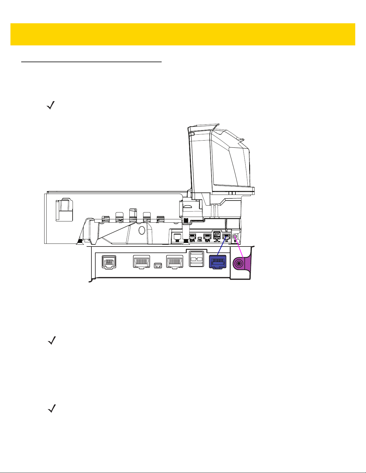
2 - 52 MP7000 Scanner Scale Integrator Guide
IBM RS-485 Interface
Connecting
NOTE For a list of supported scanner functionality by communication protocol Appendix E, Communication Protocol
Functionality.
Connect the MP70XX directly to the host interface.
POS
12V DC
Figure 2-4 IBM RS-485 Connections
To set up the MP70XX:
1. Attach the modular connector of the IBM RS-485 interface cable to the POS interface port on the MP70XX.
2. Connect the other end of the IBM RS-485 interface cable to the appropriate port on the host (typically Port 9).
The unit should power up immediately upon connection. If not, wait for unit to power up.
NOTE Older POS systems, and/or some retailers will require use of the external power supply
PWR-BGA12V50W0WW.
3. Select the port address by scanning the appropriate barcode (refer to MP7000 Scanner Scale Barcode
Programming Guide, p/n MN-002912-xx).
4. If a scale is present in the unit, scan the appropriate scale port address (IBM Scale Port Addresses on page
2-58).
5. To modify any other parameter options, scan the appropriate barcodes in the MP7000 Scanner Scale Barcode
Programming Guide (p/n MN-002912-xx).
NOTE The only required configurations are the port addresses (IBM RS-485 port address, and a scale port address
if the model has a scale), and type directives (see Step 6). The IBM system typically controls other MP70XX
parameters.
6. To prevent the IBM POS from configuring the MP70XX, refer to the MP7000 Scanner Scale Barcode
Programming Guide for information about RS-485 and IBM USB configuration, beep, scale, and type
directives.
Page 85

Host Interfaces and Cable Pinouts 2 - 53
IBM RS-485 Host Parameters
IMPORTANTThis chapter includes port address parameters only. For additional user preferences (including IBM
Directives, refer to
(p/n MN-002912-xx).
To select the IBM RS-485 port used, scan one of the barcodes listed in Table 2-10.
NOTE 1. Scanning one of these barcodes enables the RS-485 interface on the MP70XX.
2. The port numbers in Table 2-10 are no longer physical ports on the IBM POS.
NOTE This guide includes limited parameter barcodes. For ALL MP70XX programming barcodes, refer to the
MP7000 Scanner Scale Barcode Programming Guide (p/n MN-002912-xx
Table 2-10 IBM RS-485 Port Parameters
IBM Port Addresses
the MP7000 Scanner Scale Barcode Programming Guide
Parameter Page Number
).
None Selected (default)
Hand-held Scanner Emulation (Port 9B)
Non-IBM Scanner Emulation (Port 5B)
Table-top Scanner Emulation (Port 17)
IBM Scale Port Addresses
None Selected (default)
Port 6A
Port 6B
Port 6E
2-54
2-55
2-56
2-57
2-58
2-59
2-60
2-61
Page 86

2 - 54 MP7000 Scanner Scale Integrator Guide
IBM Port Addresses
*None Selected
Page 87

IBM Port Addresses (continued)
Host Interfaces and Cable Pinouts 2 - 55
Hand-held Scanner Emulation (Port 9B)
Page 88

2 - 56 MP7000 Scanner Scale Integrator Guide
IBM Port Addresses (continued)
Non-IBM Scanner Emulation (Port 5B)
Page 89

IBM Port Addresses (continued)
Host Interfaces and Cable Pinouts 2 - 57
Tabletop Scanner Emulation (Port 17)
Page 90

2 - 58 MP7000 Scanner Scale Integrator Guide
IBM Scale Port Addresses
The scale port address must be configured for the scale to operate on the IBM RS-485 bus. The default is None
Selected.
*None Selected
Page 91

IBM Scale Port Addresses (continued)
Host Interfaces and Cable Pinouts 2 - 59
Port 6A
Page 92

2 - 60 MP7000 Scanner Scale Integrator Guide
IBM Scale Port Addresses (continued)
Port 6B
Page 93

IBM Scale Port Addresses (continued)
Host Interfaces and Cable Pinouts 2 - 61
Port 6E
Page 94

2 - 62 MP7000 Scanner Scale Integrator Guide
Connector Pins
RS-232 AUX 1
Table 2-11 RJ-45
Pin # Signal/Name Direction Description
1 N/C N/A No Connection
2 5V Out
3 GND N/A Signal Ground
4 TXD Out Serial TXD (±5.4V)
5 RXD In Serial RXD (±5.4V)
6 RTS Out Serial RTS (±5.4V)
7 CTS In Serial CTS (±5.4V)
8 Scale LED In Indicates price computational scale has returned to zero -
9 Scale Zero Out Zeros price computational scale when the Zero UI button
10 12V/150mA Out Power output for price computational scale.
RS-232 scanner 5VDC Supply
reflected in UI Scale Status LED (if enabled). I/O signals
are 5V TTL.
is pressed (if enabled). I/O signals are 5V TTL.
*
Scale Display Port
Table 2-12 RJ-11, Scale Display
Pin # Signal/Name Direction Description
1 DEBUG_TXD Out Debug serial TX
2 5V Out
3 TXD Out Scale Display serial TX (3.3V TTL)
4 RXD In Scale Display serial RX (3.3V TTL)
5 GND N/A Signal ground
6 DEBUG_RXD In Debug serial RX
* The total combined current for the USB and RS-232 peripheral ports should be less than 750mA total auxiliary
current. Each individual port should not exceed 500mA.
Auxiliary 5V output
*
Page 95

Host Interfaces and Cable Pinouts 2 - 63
RS-232 AUX 2
Table 2-13 RJ-45
Pin # Signal/Name Direction Description
1 N/C N/A No connection
2 5V Out
3 GND N/A Signal ground
4 TXD Out Serial TXD (±5.4V)
5 RXD In Serial RXD (±5.4V)
6 RTS Out Serial RTS (±5.4V)
7 CTS In Serial CTS (±5.4V)
8 N/C N/A No connection
9 N/C N/A No connection
10 12V/150mA Out Output for auxiliary device.
*The total combined current for the USB and RS-232 peripheral ports should be less than 750mA total auxiliary
current. Each individual port should not exceed 500mA.
RS-232 scanner 5V supply
NOTE 150mA maximum available between
both AUX 1 and AUX 2.
*
Checkpoint Interlock
Table 2-14 EAS Interlock Connector
Pin # Signal/Name Direction Description
1 Interlock Out Checkpoint EAS Interlock (5V 4mA PNP collector out)
2 GND N/A Signal ground
Page 96

2 - 64 MP7000 Scanner Scale Integrator Guide
AUX A-B (Stacked USB)
NOTE An additional USB port is available in the front under the platter. All USB ports can be used for the
USB staging flash drive. See Table 1-3 on page 1-15 and USB Staging Flash Drive on page 5-10
for additional information.
Table 2-15 Stacked USB Port
Pin # Signal/Name Direction Description
1 5V Out
2 D- Bidirectional USB D-
3 D+ Bidirectional USB D+
4 GND N/A Signal ground
*The total combined current for the USB and RS-232 peripheral ports should be less than 750mA total auxiliary
current. Each individual port should not exceed 500mA.
USB 5V output
*
POS
Table 2-16 RJ-45, Primary POS
Pin # Signal/Name Direction Description
1 DETECT Out USB cable detect output
2 5V In USB cable 5V detect input
3 GND N/A Signal ground
4 TXD/IBM-A Bidirectional Multiplexed serial TXD/IBM-A
5 RXD/D+ Bidirectional Multiplexed serial RXD/USB D+
6 RTS/IBM-B Bidirectional Multiplexed serial RTS/IBM-B
7 CTS/USB D- Bidirectional Multiplexed serial CTS/USB D
8 DOWNLOAD In POS download
9 N/C N/A No connection
10 12V In Terminal 12VDC to MP70XX
(Power From Terminal)
*Terminal systems vary in power capabilities. Ensure your system power supply is capable of the MP70XX
configuration power requirements. For terminals unable to support P.O.T., a 12V DC barrel jack is available for
external power.
*
Page 97

Host Interfaces and Cable Pinouts 2 - 65
12V DC
Table 2-17 12V DC Jack, 2.5mm
Pin # Signal/Name Direction Description
1 EXT 12V In Center pin: 12VDC (primary power)
2 GND N/A Barrel: signal ground
Page 98

2 - 66 MP7000 Scanner Scale Integrator Guide
Page 99

CHAPTER 3 SITE PREPARATION
AND INSTALLATION
Introduction
The MP7000 Scanner Scale was designed to drop into an existing bioptic checkstand cutout with no modifications.
The unit is available in three industry standard sizes (for more detailed information, see Appendix B, Technical
Specifications):
• Short - no scale available
Length: 13.9 in. (351.0 mm)
Width: 11.5 in. (292.0 mm)
• Medium - with or without scale
Length: 15.7 in. (398.0 mm)
Width: 11.5 in. (292.0 mm)
• Long - with or without scale
Length: 20.0 in. (506.0 mm)
Width: 11.5 in. (292.0 mm)
Page 100

3 - 2 MP7000 Scanner Scale Integrator Guide
Site Preparation
IMPORTANTThis guide does not encompass all factors related to worker safety and check stand design. It does offer
a list of considerations which may be helpful in ensuring greater safety and productivity.
Ventilation and Spacing Requirements
The scanner/scale housing was designed to provide adequate space for ventilation and drainage for spills. Figure
3-1 shows the drainage holes, under the platter, for possible spills that may occur when scanning/weighing items.
Checkstand ventilation may be required to ensure the MP70XX temperature limits are not exceeded. If forced air
ventilation is used, it must not pass through the MP70XX as this can produce an unstable weighing environment.
The ambient air temperature inside the checkstand, adjacent to the device, must not exceed 104°F (40°C).
MP70XX Top View
(Drainage/Ventilation Holes on Both Sides)
Figure 3-1 Drainage/Ventilation Holes
(Drainage/Ventilation Holes on Both Sides)
MP70XX Side View
Service Access Requirements
The MP70XX was engineered to allow performance of all routine service and maintenance (including scale
zeroing, and calibration) without removing the scanner from the counter.
Service must be performed by a Zebra Certified Repair Provider who has completed the Service Repair Training
course, and (if applicable) the Scale Calibration Training course. For MP7001 and MP7002 scanner/scales,
depending on the region of installation, a certified Weights & Measures technician is required to place the device in
trade before using, and after certain repairs.
 Loading...