

Page 1

MC9500-K
MOBILE COMPUTER
USER GUIDE
Page 2

Page 3

MC9500-K Mobile Computer
User Guide
72E-118501-05
Rev. A
April 2015
Page 4

ii MC9500-K Mobile Computer User Guide
© 2015 ZIH Corp.
No part of this publication may be reproduced or used in any form, or by any electrical or mechanical means,
without permission in writing from Zebra. This includes electronic or mechanical means, such as photocopying,
recording, or information storage and retrieval systems. The material in this manual is subject to change
without notice.
The software is provided strictly on an “as is” basis. All software, including firmware, furnished to the user is on
a licensed basis. Zebra grants to the user a non-transferable and non-exclusive license to use each software
or firmware program delivered hereunder (licensed program). Except as noted below, such license may not be
assigned, sublicensed, or otherwise transferred by the user without prior written consent of Zebra. No right to
copy a licensed program in whole or in part is granted, except as permitted under copyright law. The user shall
not modify, merge, or incorporate any form or portion of a licensed program with other program material, create
a derivative work from a licensed program, or use a licensed program in a network without written permission
from Zebra. The user agrees to maintain Zebra’s copyright notice on the licensed programs delivered
hereunder, and to include the same on any authorized copies it makes, in whole or in part. The user agrees not
to decompile, disassemble, decode, or reverse engineer any licensed program delivered to the user or any
portion thereof.
Zebra reserves the right to make changes to any software or product to improve reliability, function, or design.
Zebra does not assume any product liability arising out of, or in connection with, the application or use of any
product, circuit, or application described herein.
No license is granted, either expressly or by implication, estoppel, or otherwise under any Zebra intellectual
property rights. An implied license only exists for equipment, circuits, and subsystems contained in Zebra
products.
Page 5

Revision History
Changes to the original manual are listed below:
Change Date Description
-01 Rev. A 09/02/09 Initial release.
-02 Rev. A 05/15/10 Add support for new memory configurations and Windows Mobile 6.5.3.
-03 Rev. A 06/28/10 Add support for MC959B-K configuration.
-03 Rev. B 07/30/11 Add original microSD card installation and removal procedures.
-04 Rev A 09/30/14 Add 5250 Emulator and VT Emulator keypads. Add 7200 mAh battery
iii
support.
-05 Rev A
04/2015
Zebra Rebranding
Page 6

iv MC9500-K Mobile Computer User Guide
Page 7

Table of Contents
Revision History.................................................................................................................................... iii
About This Guide
Introduction ........................................................................................................................................... xiii
Documentation Set ......................................................................................................................... xiii
Configurations....................................................................................................................................... xiv
Keypads.......................................................................................................................................... xiv
Software Versions........................................................................................................................... xiv
Chapter Descriptions ............................................................................................................................ xvii
Notational Conventions......................................................................................................................... xvii
Related Documents .............................................................................................................................. xviii
Service Information............................................................................................................................... xviii
Chapter 1: Getting Started
Introduction .......................................................................................................................................... 1-1
Unpacking ............................................................................................................................................ 1-1
Part of the MC9500-K .......................................................................................................................... 1-2
Getting Started ..................................................................................................................................... 1-3
Installing a microSD Card .............................................................................................................. 1-3
Version 1 .................................................................................................................................. 1-3
Version 2 .................................................................................................................................. 1-4
Installing the SIM Card ................................................................................................................... 1-5
Installing the Battery ...................................................................................................................... 1-7
Charging the Battery ...................................................................................................................... 1-7
Charging Temperature ............................................................................................................. 1-9
Powering On the MC9500-K .......................................................................................................... 1-9
Calibrating the Screen ............................................................................................................. 1-9
Replacing the Battery .......................................................................................................................... 1-9
Removing the microSD Card ............................................................................................................... 1-10
Removing the SIM Card ...................................................................................................................... 1-11
Page 8

vi MC9500-K Mobile Computer User Guide
Chapter 2: Battery Management
Introduction .......................................................................................................................................... 2-1
Battery Functionality ............................................................................................................................ 2-1
Battery Health ................................................................................................................................ 2-2
Battery Status ...................................................................................................................................... 2-3
Installed in an MC9500-K ............................................................................................................... 2-3
In a Charger ................................................................................................................................... 2-5
Stand-alone .................................................................................................................................... 2-8
Charging the MC9500-K ...................................................................................................................... 2-9
Charging a Spare Battery .................................................................................................................... 2-11
Charging Temperature ................................................................................................................... 2-12
Power Saving Techniques ................................................................................................................... 2-13
Changing the Power Settings ........................................................................................................ 2-13
Changing the Backlight Settings .................................................................................................... 2-13
Changing the Keypad Backlight Settings ....................................................................................... 2-13
Turning Off the Radios ................................................................................................................... 2-13
Chapter 3: Using the MC9500-K
Introduction .......................................................................................................................................... 3-1
LED Indicators ..................................................................................................................................... 3-1
Resetting the MC9500-K ..................................................................................................................... 3-3
Performing a Warm Boot ............................................................................................................... 3-3
Performing a Cold Boot .................................................................................................................. 3-3
Waking the MC9500-K ......................................................................................................................... 3-3
Locking the MC9500-K ........................................................................................................................ 3-4
Keypad Locking ............................................................................................................................. 3-4
Password Locking .......................................................................................................................... 3-5
Keypads ............................................................................................................................................... 3-7
Function Buttons .................................................................................................................................. 3-7
Stylus ................................................................................................................................................... 3-7
Entering Data ....................................................................................................................................... 3-8
Interactive Sensor Technology ............................................................................................................ 3-9
Power Management ....................................................................................................................... 3-9
Display Orientation ......................................................................................................................... 3-9
Free Fall Detection ......................................................................................................................... 3-10
Today Screen ...................................................................................................................................... 3-11
Status Icons ......................................................................................................................................... 3-12
Programs ............................................................................................................................................. 3-14
Settings ................................................................................................................................................ 3-17
Adjusting Volume ................................................................................................................................. 3-20
Battery Status Indications .................................................................................................................... 3-21
Battery Reserve Options ................................................................................................................ 3-21
Main Battery Temperature Notifications ......................................................................................... 3-22
Using Voice-Over-IP ............................................................................................................................ 3-23
Infrared Connection ............................................................................................................................. 3-24
Exchanging Files using IR Connection .................................................................................... 3-24
Printing ................................................................................................................................................. 3-25
Page 9

Table of Contents vii
Chapter 4: Data Capture
Introduction .......................................................................................................................................... 4-1
Laser Scanning .................................................................................................................................... 4-1
Scanning Considerations ............................................................................................................... 4-1
Laser Scanning .............................................................................................................................. 4-2
Decode Zones ................................................................................................................................ 4-3
Imaging ................................................................................................................................................ 4-5
Operational Modes ......................................................................................................................... 4-6
Imager Scanning ............................................................................................................................ 4-6
Imager Decode Ranges ................................................................................................................. 4-8
Color Digital Camera ........................................................................................................................... 4-9
Digital Camera Scanning ............................................................................................................... 4-9
Taking Photos ................................................................................................................................ 4-10
Recording Video ............................................................................................................................ 4-10
Viewing Photos and Videos ........................................................................................................... 4-11
Chapter 5: Using the Phone
Introduction .......................................................................................................................................... 5-1
Accessing the Phone Keypad .............................................................................................................. 5-1
Turning the Phone On and Off ............................................................................................................. 5-2
Audio Modes ........................................................................................................................................ 5-3
Using a Wired Headset .................................................................................................................. 5-3
Using a Bluetooth Headset ............................................................................................................ 5-4
Adjusting Audio Volume ................................................................................................................. 5-5
Hearing Aid Compatibility Setting ........................................................................................................ 5-5
Making a Call ....................................................................................................................................... 5-6
Using the Phone ............................................................................................................................ 5-6
Using Contacts ............................................................................................................................... 5-6
Creating an Outlook Contact .................................................................................................... 5-7
Editing an Outlook Contact ...................................................................................................... 5-7
Deleting a Contact ................................................................................................................... 5-8
Creating a SIM Contact ............................................................................................................ 5-8
Using Call History .......................................................................................................................... 5-8
Making a Speed Dial Call ............................................................................................................... 5-9
Making an Emergency Call .................................................................................................................. 5-10
Answering a Call .................................................................................................................................. 5-10
Incoming Call Features .................................................................................................................. 5-10
Smart Dialing ....................................................................................................................................... 5-11
Muting a Call ........................................................................................................................................ 5-12
Taking Notes ........................................................................................................................................ 5-12
Using Speed Dial ................................................................................................................................. 5-13
Adding a Speed Dial Entry ............................................................................................................. 5-13
Editing a Speed Dial Entry ............................................................................................................. 5-15
Deleting a Speed Dial Entry ........................................................................................................... 5-16
Using Call History ................................................................................................................................ 5-16
Managing Call History .................................................................................................................... 5-16
Changing the Call History View ............................................................................................... 5-17
Resetting the Recent Calls Counter ......................................................................................... 5-17
Deleting Call History Items by Call Date .................................................................................. 5-18
Page 10

viii MC9500-K Mobile Computer User Guide
Deleting All Call History Items .................................................................................................. 5-18
Viewing Call Status .................................................................................................................. 5-18
Using the Call History Menu .................................................................................................... 5-19
Swapping Calls on an MC9596 ........................................................................................................... 5-20
Swapping Calls on an MC9598 ........................................................................................................... 5-20
Conference Calling on an MC9596 ...................................................................................................... 5-21
Three-way Calling on an MC9598 ....................................................................................................... 5-23
Text Messaging ................................................................................................................................... 5-24
Viewing Text Messages ................................................................................................................. 5-24
Sending a Text Message ............................................................................................................... 5-26
Establishing a GSM Data Connection (MC9596-K and MC959B-K) ................................................... 5-28
Ending a Data Connection ............................................................................................................. 5-29
Establishing an CDMA Data Connection (MC9598-K and MC959B-K) ............................................... 5-30
Ending a Data Connection ............................................................................................................. 5-31
Switching Carrier Networks ................................................................................................................. 5-31
Chapter 6: Using GPS Navigation
Introduction .......................................................................................................................................... 6-1
Software Installation ............................................................................................................................ 6-1
MC9500-K GPS Setup ......................................................................................................................... 6-1
Operation ............................................................................................................................................. 6-2
GPS Maps on microSD Cards ....................................................................................................... 6-2
Answering a Phone Call While Using GPS .................................................................................... 6-2
Losing the GPS Signal While in a Vehicle ..................................................................................... 6-2
Assisted GPS ....................................................................................................................................... 6-2
Chapter 7: Using Bluetooth
Introduction .......................................................................................................................................... 7-1
Adaptive Frequency Hopping .............................................................................................................. 7-1
Security ................................................................................................................................................ 7-2
Bluetooth Configuration ....................................................................................................................... 7-3
Bluetooth Power States ....................................................................................................................... 7-4
Cold Boot ................................................................................................................................. 7-4
Warm Boot ............................................................................................................................... 7-4
Suspend ................................................................................................................................... 7-4
Resume .................................................................................................................................... 7-5
Using Microsoft Bluetooth Stack .......................................................................................................... 7-5
Turning the Bluetooth Radio Mode On and Off .............................................................................. 7-5
Enabling Bluetooth ................................................................................................................... 7-5
Disabling Bluetooth .................................................................................................................. 7-6
Discovering Bluetooth Device(s) .................................................................................................... 7-6
Available Services .......................................................................................................................... 7-8
Object Push Services via Beam ............................................................................................... 7-9
Internet Sharing ....................................................................................................................... 7-10
Hands-free Services ................................................................................................................ 7-11
Serial Port Services ................................................................................................................. 7-12
ActiveSync Using Serial Port Services .................................................................................... 7-13
Phone Book Access Profile Services ....................................................................................... 7-14
Page 11

Table of Contents ix
Dial-Up Networking Services ................................................................................................... 7-15
Connect to a HID Device ......................................................................................................... 7-15
A2DP/AVRCP Services ........................................................................................................... 7-15
Using StoneStreet One Bluetooth Stack .............................................................................................. 7-17
Turning the Bluetooth Radio Mode On and Off .............................................................................. 7-17
Disabling Bluetooth .................................................................................................................. 7-17
Enabling Bluetooth ................................................................................................................... 7-17
Modes ............................................................................................................................................ 7-17
Wizard Mode ............................................................................................................................ 7-18
Explorer Mode .......................................................................................................................... 7-18
Discovering Bluetooth Device(s) .................................................................................................... 7-18
Available Services .......................................................................................................................... 7-21
File Transfer Services .............................................................................................................. 7-22
Connecting to the Internet Using an Access Point ................................................................... 7-24
Dial-Up Networking Services ................................................................................................... 7-24
Object Exchange Push Services .............................................................................................. 7-25
Headset Services ..................................................................................................................... 7-29
Hands-free Services ................................................................................................................ 7-30
Serial Port Services ................................................................................................................. 7-30
ActiveSync Using Serial Port Services .................................................................................... 7-31
Personal Area Network Services ............................................................................................. 7-32
IrMC Synchronization Services ................................................................................................ 7-32
A2DP/AVRCP Services ........................................................................................................... 7-32
Connect to a HID Device ......................................................................................................... 7-33
Bonding with Discovered Device(s) ............................................................................................... 7-34
Bluetooth Settings .......................................................................................................................... 7-36
Device Info Tab ........................................................................................................................ 7-36
Services Tab ............................................................................................................................ 7-37
Security Tab ............................................................................................................................. 7-44
Discovery Tab .......................................................................................................................... 7-45
Virtual COM Port Tab ............................................................................................................... 7-45
HID Tab .................................................................................................................................... 7-46
Profiles Tab .............................................................................................................................. 7-47
System Parameters Tab .......................................................................................................... 7-48
Miscellaneous Tab ................................................................................................................... 7-48
Chapter 8: Accessories
Introduction .......................................................................................................................................... 8-1
Universal Accessory System ............................................................................................................... 8-3
Single Bay USB Cradle ........................................................................................................................ 8-4
Communication and Charging the MC9500-K Battery ................................................................... 8-4
Single Slot Battery Charger ................................................................................................................. 8-6
Charging the Battery ...................................................................................................................... 8-6
Four Bay Charge Only Cradle ............................................................................................................. 8-7
Charging ........................................................................................................................................ 8-7
Four Bay Ethernet Cradle .................................................................................................................... 8-9
Communication and Charging ....................................................................................................... 8-9
LED Indicators ............................................................................................................................... 8-10
Speed LED ............................................................................................................................... 8-10
Page 12

x MC9500-K Mobile Computer User Guide
Link LED .................................................................................................................................. 8-10
Four Slot Battery Charger .................................................................................................................... 8-11
Battery Charging ............................................................................................................................ 8-11
Vehicle Cradle ..................................................................................................................................... 8-12
Charging the MC9500-K Battery .................................................................................................... 8-12
Vehicle Battery Charger ....................................................................................................................... 8-13
Charging the Battery ...................................................................................................................... 8-13
Magnetic Stripe Reader ....................................................................................................................... 8-14
Attaching and Removing the MSR ................................................................................................. 8-14
Using the MSR ............................................................................................................................... 8-14
Cables .................................................................................................................................................. 8-16
Battery Charging and Operating Power ......................................................................................... 8-17
Chapter 9: Maintenance & Troubleshooting
Introduction .......................................................................................................................................... 9-1
Maintaining the MC9500-K .................................................................................................................. 9-1
Removing the Screen Protector ........................................................................................................... 9-2
Battery Safety Guidelines .................................................................................................................... 9-2
Cleaning ............................................................................................................................................... 9-3
Materials Required ......................................................................................................................... 9-3
Cleaning the MC9500-K ................................................................................................................. 9-4
Housing .................................................................................................................................... 9-4
Display ..................................................................................................................................... 9-4
Scanner Exit Window ............................................................................................................... 9-4
Interface Connector ................................................................................................................. 9-4
Battery Contacts ...................................................................................................................... 9-4
Cleaning Cradle Connectors .......................................................................................................... 9-5
Cleaning Frequency ....................................................................................................................... 9-5
Troubleshooting ................................................................................................................................... 9-6
MC9500-K ...................................................................................................................................... 9-6
Bluetooth Connection ..................................................................................................................... 9-8
Single Bay USB Cradle ................................................................................................................. 9-9
Single Slot Battery Charger ........................................................................................................... 9-10
Four Bay Ethernet Cradle .............................................................................................................. 9-10
Four Bay Charge Only Cradle ........................................................................................................ 9-11
Vehicle Cradle ................................................................................................................................ 9-12
Four Slot Battery Charger .............................................................................................................. 9-13
Cables ............................................................................................................................................ 9-13
Magnetic Stripe Reader ................................................................................................................. 9-14
Appendix A: Technical Specifications
MC9500-K Technical Specifications .................................................................................................... A-1
MC9500-K ...................................................................................................................................... A-1
MC9500-K Accessory Specifications ................................................................................................... A-7
Single Bay USB Cradle .................................................................................................................. A-7
Single Slot Battery Charger ........................................................................................................... A-7
Four Bay Ethernet Cradle .............................................................................................................. A-8
Four Bay Charge Only Cradle ........................................................................................................ A-9
Page 13

Table of Contents xi
Four Slot Battery Charger .............................................................................................................. A-9
Magnetic Stripe Reader ................................................................................................................. A-10
Vehicle Cradle ................................................................................................................................ A-11
Vehicle Battery Charger ................................................................................................................. A-11
Appendix B: Voice Quality Manager
Introduction .......................................................................................................................................... B-1
Features ............................................................................................................................................... B-1
Enabling VQM ...................................................................................................................................... B-1
Audio Modes ........................................................................................................................................ B-2
Changing Audio Modes .................................................................................................................. B-2
Voice Packet Prioritization ................................................................................................................... B-3
Limitations ...................................................................................................................................... B-4
Acoustic Echo Cancellation ............................................................................................................ B-4
Disabling VQM ..................................................................................................................................... B-4
Appendix C: Keypads
Introduction .......................................................................................................................................... C-1
Alpha Primary Keypad ......................................................................................................................... C-2
Alpha Numeric Keypad ........................................................................................................................ C-6
Calculator Numeric Keypad ................................................................................................................. C-10
Telephony Numeric Keypad ................................................................................................................ C-14
Special Character Key ......................................................................................................................... C-18
Appendix D: Windows Mobile 6.5
Introduction .......................................................................................................................................... D-1
Finger Scrolling .................................................................................................................................... D-1
Home Screen ....................................................................................................................................... D-1
Classic Today Screen .................................................................................................................... D-3
Status Bar ...................................................................................................................................... D-5
Tile Bar ........................................................................................................................................... D-8
Start Screen ................................................................................................................................... D-8
Speaker Icon .................................................................................................................................. D-14
Battery Icons .................................................................................................................................. D-14
Connectivity Icon ............................................................................................................................ D-14
Locking the MC9500-K ........................................................................................................................ D-15
Microsoft Locking ........................................................................................................................... D-15
Password Locking .......................................................................................................................... D-16
Using the RS507 Hands-free Imager ................................................................................................... D-18
Removing the Battery .......................................................................................................................... D-18
Battery Removal ............................................................................................................................ D-18
Suspend Mode ............................................................................................................................... D-19
Assisted GPS ....................................................................................................................................... D-19
Glossary
Page 14

xii MC9500-K Mobile Computer User Guide
Index
Page 15

About This Guide
Introduction
This guide provides information about using the MC9500-K mobile computers and accessories.
NOTE Screens and windows pictured in this guide are samples and can differ from actual screens.
For configurations with OEM version 02.27.000X and Windows Mobile 6.5 operating system, refer to
Appendix D, Windows Mobile 6.5 for information about new features.
Documentation Set
The documentation set for the MC9500-K provides information for specific user needs, and includes:
•
MC9500-K Quick Start Guide - describes how to get the MC9500-K mobile computer up and running.
•
MC9500-K Mobile Computer User Guide - describes how to use the MC9500-K mobile computer.
•
MC9500-K Mobile Computer Integrator Guide - describes how to set up the MC9500-K mobile computer
and accessories.
•
Microsoft® Applications for Windows Mobile® 6 User Guide - describes how to use Microsoft developed
applications.
•
Application Guide - describes how to use Enterprise Mobility developed sample applications.
•
Enterprise Mobility Developer Kit (EMDK) Help File - provides API information for writing applications.
Page 16

xiv MC9500-K Mobile Computer User Guide
Configurations
This guide covers the following configurations:
Configuration Radios Display Memory
MC9590 WLAN: 802.11 a/b/g
WPAN: Bluetooth
v2.1 with EDR
GPS: SiRF III
MC9596 WLAN: 802.11a/b/g
WPAN: Bluetooth
v2.1 with EDR
WWAN: HSDPA
GPS: SiRF III
MC9598 WLAN: 802.11a/b/g
WPAN: Bluetooth
v2.1 with EDR
WWAN: EvDO Rev.
A
GPS: SiRF III
MC959B WLAN: 802.11a/b/g
WPAN: Bluetooth
v2.1 with EDR
WWAN: CDMA or
GSM Data
GPS: SiRF III
3.7” VGA
Color
3.7” VGA
Color
3.7” VGA
Color
3.7” VGA
Color
128 MB RAM/
512 MB Flash
or 256 MB
RAM/1 GB
Flash
128 MB RAM/
512 MB Flash
or 256 MB
RAM/1 GB
Flash
128 MB RAM/
512 MB Flash
or 256 MB
RAM/1 GB
Flash
256 MB
RAM/1 GB
Flash
Data Capture
Options
1D laser
scanner,
2D imager,
1D laser
scanner and
camera or
2D imager and
camera
1D laser
scanner,
2D imager,
1D laser
scanner and
camera or
2D imager and
camera
1D laser
scanner,
2D imager,
1D laser
scanner and
camera or
2D imager and
camera
1D laser
scanner,
2D imager,
1D laser
scanner and
camera or
2D imager and
camera
Operating
System
Windows
Mobile®6.X
Classic
Windows
®
Mobile
Professional
Windows
Mobile
Professional
Windows
Mobile
Professional
®
®
6.X
6.X
6.1
Keypads
See Keypads
below.
See Keypads
below.
See Keypads
below.
See Keypads
below.
Keypads
The following keypads are available:
•
Alpha Primary
•
Telephony Numeric
•
Calculator Numeric
•
Alpha Numeric
•
5350 Emulator
•
VT Emulator.
See Appendix C, Keypads for specific keypad information.
Page 17

About This Guide xv
Software Versions
This guide covers various software configurations and references are made to operating system or software
versions for:
•
Adaptation Kit Update (AKU) version
•
OEM version
•
BTExplorer version
•
Fusion version
•
Phone version.
AKU Version
To determine the Adaptation Kit Update (AKU) version:
Ta p Start > Settings > System tab > About icon > Version tab.
The second line lists the operating system version and the build number. The last part of the build number
represents the AKU number. For example, Build 20963.1.5.2 indicates that the device is running AKU version
1.5.2.
OEM Version
To determine the OEM software version:
Ta p Start > Settings > System tab > System Info icon > System tab.
Page 18

xvi MC9500-K Mobile Computer User Guide
MC95
BTExplorer Software
NOTE BTExplorer application is only available when the StoneStreet One Bluetooth stack is enabled. Refer to
the MC9500-K Mobile Computer Integrator Guide for information on selecting the Bluetooth stack.
To determine the BTExplorer software version:
Ta p
BTExplorer icon > Show BTExplorer> File > About.
Fusion Software
To determine the Fusion software version:
Ta p Fusion Signal Strength icon > Wireless Status > Versions.
Page 19

About This Guide xvii
Phone Software
To determine the Phone software version:
On MC9596-K, tap Start > Phone > Menu > Options > PhoneInfo tab. On MC9598-K tap Start > Phone > Menu
> Options > Version Information tab. On MC959B-K tap Start > Settings > Broadband Settings.
Chapter Descriptions
Topics covered in this guide are as follows:
•
Chapter 1, Getting Started provides information on getting the MC9500-K up and running for the first time.
•
Chapter 2, Battery Management provides information on the types of batteries and how to charge them.
•
Chapter 3, Using the MC9500-K provides information on using the MC9500-K.
•
Chapter 4, Data Capture provides instructions for using the MC9500-K to capture data using the laser
scanner, imager and camera.
•
Chapter 5, Using the Phone provides basic instructions for using the MC9500-K phone.
•
Chapter 6, Using GPS Navigation provides information about GPS navigation with the MC9500-K.
•
Chapter 7, Using Bluetooth explains Bluetooth functionality on the MC9500-K.
•
Chapter 8, Accessories describes the available accessories and how to use them with the MC9500-K.
Page 20

xviii MC9500-K Mobile Computer User Guide
•
Chapter 9, Maintenance & Troubleshooting includes instructions on cleaning and storing the MC9500-K, and
provides troubleshooting solutions for potential problems during MC9500-K operation.
•
Appendix A, Technical Specifications provides the technical specifications for the MC9500-K.
•
Appendix B, Voice Quality Manager provides information on Voice Quality Manager software.
•
Appendix C, Keypads provides keypad layouts and operation.
•
Appendix D, Windows Mobile 6.5 explains the new features in Windows Mobile 6.5.3.
Notational Conventions
The following conventions are used in this document:
•
“Mobile computer” refers to the Zebra MC9500-K hand-held computer.
•
Italics are used to highlight the following:
• Chapters and sections in this and related documents
• Icons on a screen.
•
Bold text is used to highlight the following:
• Dialog box, window, and screen names
• Drop-down list and list box names
• Check box and radio button names
• Key names on a keypad
• Button names on a screen.
•
Bullets (•) indicate:
• Action items
• Lists of alternatives
• Lists of required steps that are not necessarily sequential
•
Sequential lists (e.g., those that describe step-by-step procedures) appear as numbered lists.
Related Documents
•
MC9500-K Quick Start Guide, p/n 72-118504-xx.
•
MC95XX Series Windows Mobile® 6.1 Regulatory Guide, p/n 72-118502-xx.
•
MC9500-K Mobile Computer Integrator Guide, p/n 72E-118503-xx.
•
Mobility Services Platform User Guide, p/n 72E-100158-xx.
•
Wireless Fusion Enterprise Mobility Suite User Guide for Version 3.00, p/n 72E-122495-xx.
•
Microsoft® Applications for Windows Mobile® 6 User Guide, p/n 72E-108299-xx.
•
Application Guide, p/n 72E-68901-xx.
•
Enterprise Mobility Developer Kits (EMDKs), available at: http://www.zebra.com/support.
•
Latest ActiveSync software, available at: http://www.microsoft.com.
Page 21

For the latest version of this guide and all guides, go to: http://www.zebra.com/support.
(S)S/N XXXXXXXXXXXXXX
MODEL: XXXXXX
P/N: XXXXXXXXXXXXXX
Manufacturing Label
Service Information
If you have a problem with your equipment, contact Zebra for your region. Contact information is available at:
http://www.zebra.com/support
When contacting support, please have the following information available:
•
Serial number of the unit (found on manufacturing label)
•
Model number or product name (found on manufacturing label)
•
Software type and version number.
About This Guide xix
.
Zebra responds to calls by email or telephone within the time limits set forth in support agreements.
If your problem cannot be solved by Zebra, you may need to return your equipment for servicing and will be given
specific directions. Zebra is not responsible for any damages incurred during shipment if the approved shipping
container is not used. Shipping the units improperly can possibly void the warranty.
If you purchased your business product from a Zebra business partner, contact that business partner for support.
Page 22

xx MC9500-K Mobile Computer User Guide
Page 23

Chapter 1 Getting Started
Introduction
This chapter explains how to set up the MC9500-K for the first time.
Unpacking
Carefully remove all protective material from the MC9500-K and save the shipping container for later storage and
shipping.
Verify that you received the following:
•
MC9500-K mobile computer
•
4800 mAh Lithium-ion battery
•
Regulatory Guide
•
Quick Start Guide.
Inspect the equipment for damage. If any equipment is missing or damaged, contact the Zebra center immediately.
See page xix for contact information.
Prior to using the MC9500-K for the first time, remove the protective shipping film that covers the keypad and
battery display.
Page 24

1 - 2 MC9500-K Mobile Computer User Guide
Scan
Button
Modular Keypad
(Alpha Primary
Keypad Shown)
Power Button
Volume
Up/Down Button
Touch Screen with
Protective Overlay
Microphone
Function Keys
Battery
Camera Flash (Optional)
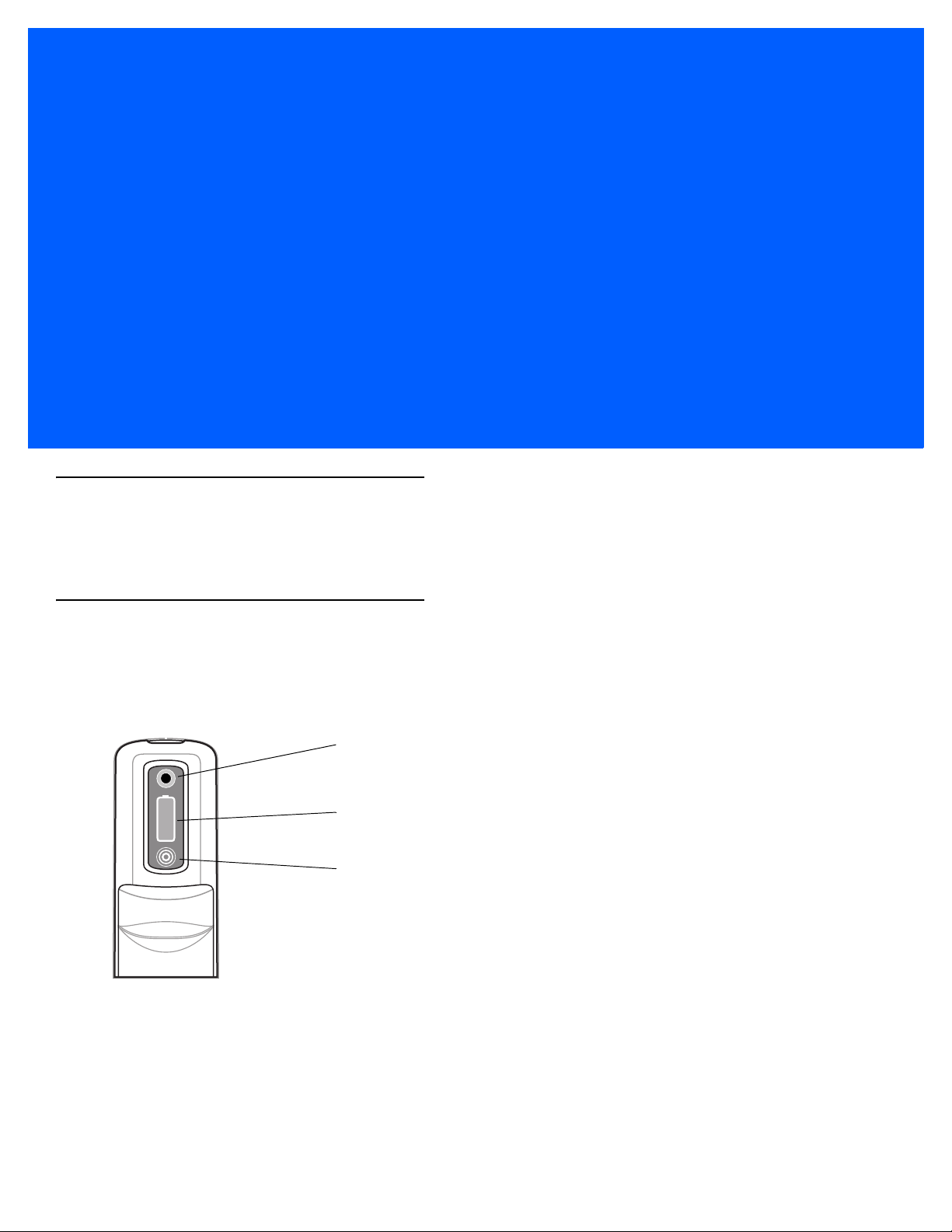
Exit Window
Headset Connector
Speaker
Interface Connector
Scan Button
Camera (Optional)
Programmable Button
IrDA Window
Battery Release
Latch
Stylus
Interface Pocket
Battery Release
Latch
Interface Plate
Handstrap
Part of the MC9500-K
Figure 1-1
MC9500-K
Page 25

Getting Started
SD Card Cover
Flathead Screwdriver
To start using the MC9500-K for the first time:
•
Install a microSD card (optional)
•
Install the SIM card (MC9596 only)
•
Install the battery.
•
Charge the MC9500-K.
Installing a microSD Card
The microSD card slot provides secondary non-volatile storage. The slot is located under the battery pack. Refer to
the documentation provided with the card for more information, and follow the manufacturer’s recommendations for
use.
CAUTION Follow proper ESD precautions to avoid damaging the microSD card. Proper ESD precautions include,
Getting Started 1 - 3
but are not limited to, working on an ESD mat and ensuring that the operator is properly grounded.
NOTE The MC9500-K was manufactured with two types of microSD card holders.
In Version 1, the microSD card is placed in the holder door and the door closed and locked into place.
In Version 2, the microSD card is placed face down on the holder contacts and the door closed and locked into
place.
Version 1
To install the microSD card:
1. Remove the SD card cover using flathead screwdriver.
Figure 1-2
2. Slide the microSD card holder door to the left to open.
3. Lift microSD card holder door.
SD Card Cover Removal
Page 26

1 - 4 MC9500-K Mobile Computer User Guide
microSD Card Holder Door
microSD card
Holding tab
SD Card Cover
Stylus
Figure 1-3
4. Insert the microSD card into card holder door ensuring that the card slides into the holding tabs on each side of
Lift microSD Card Holder Door
the door.
Figure 1-4
5. Close the card holder door and slide to the right to lock into place.
6. Align the SD card cover over the access hole and press down until it snaps into place.
Insert microSD Card in Holder
Version 2
To install the microSD card:
1. Remove the SD card cover using the end of the stylus.
Figure 1-5
2. Slide the microSD card holder door to the left to unlock.
3. Lift the microSD card holder door.
SD Card Cover Removal
Page 27

Getting Started 1 - 5
microSD Card Holder Door
11
2
microSD card
Figure 1-6
4. Place the microSD card onto the contacts.
Figure 1-7
5. Close the card holder door and slide to the right to lock into place.
6. Align the SD card cover over the access hole and press down until it snaps into place.
Lift microSD Card Holder Door
Insert microSD Card in Holder
Installing the SIM Card
NOTE MC9596 and MC959B configuration only.
GSM phone service requires a Subscriber Identification Module (SIM) card, or smart card. Obtain the card from the
your service provider. The card fits into the MC9596 and can contain the following information:
•
Mobile phone service provider account details.
•
Information regarding service access and preferences.
•
Contact information, which can be moved to Contacts on the MC9596.
•
Any additional services to which you have subscribed.
To install the SIM card:
1. Remove SIM card cover using the end of the stylus.
NOTE For more information about SIM cards, refer to the service provider's documentation.
Page 28

1 - 6 MC9500-K Mobile Computer User Guide
Card Notch
Figure 1-8
2. Slide the SIM card holder door to the left to unlock.
3. Lift the SIM card holder door.
Figure 1-9
4. Insert the SIM card, as shown in Figure 1-10 into the holder door with the contacts facing down and the card
SIM Card Cover Removal
Lifting the SIM Cover
notch facing up.
Figure 1-10
5. Close SIM card holder door and slide to the right to lock into place.
6. Align the SIM card cover over the access hole and press down until it snaps into place.
Inserting the SIM Card
Page 29

7. Install the battery.
Battery
Battery Release Latch
Battery Release Latch
8. After completing initial MC9596 setup or after replacing a SIM card:
a. Press the red Power button.
b. On the Today screen, tap Wireless Manager.
c. Ensure Phone is on.
d. Press the red Power button to suspend the MC9596.
e. Perform a warm boot. See Resetting the MC9500-K on page 3-3.
f. Make a call to verify cellular connection.
NOTE For detailed information about WWAN activation and settings, refer to the MC9500-K Series Mobile Computer
Integrator Guide.
Installing the Battery
To install the battery:
1. Insert the battery, top first, into the battery compartment.
Getting Started 1 - 7
2. Press the battery down into the battery compartment until the battery release latches snap into place.
Figure 1-11
3. The MC9500-K powers up automatically after inserting the battery, if the battery has been charged previously.
Inserting the Battery
Charging the Battery
CAUTION Ensure that you follow the guidelines for battery safety described in Battery Safety Guidelines on page 9-2.
Before using the MC9500-K for the first time, charge the battery using either a charging cable or a cradle:
NOTE For cable and cradle setup and charging procedures refer to the MC9500-K Series Mobile
•
USB Charging Cable
•
Charge Only Cable
•
Single Bay USB Cradle
Computer Integrator Guide.
Page 30

1 - 8 MC9500-K Mobile Computer User Guide
Battery Status LED
•
Four Bay Charge Only Cradle
•
Four Bay Ethernet Cradle.
Align and hook the MC9500-K interface pocket onto the cradle’s or cable’s cleat. The battery automatically begins
charging. See Table 1-1 for charging indications. The 4800 mAh battery fully charges in less than six hours.
Battery Status LED
Table 1-1
Off Indicates that the:
Slow Blinking Amber
(1 blink every 2 seconds)
Slow Blinking Red
(1 blink every 2 seconds)
Solid Green Indicates that a healthy battery is fully charged.
Solid Red Indicates that an unhealthy battery is fully charged.
Fast Blinking Amber
(2 blinks/second)
Single Blink Amber (when
Power button pressed)
LED Charge Indicators
Battery Status LED Indication
•
battery is not charging
•
MC9500-K is not connected correctly to the cradle or not connected to a
p
ower source.
•
cradle is not powered.
Indicates that a healthy battery is charging.
Indicates that an unhealthy battery is charging.
Indicates a charging error, e.g.:
•
temperature is too low or too high.
•
charging has gone on too long without completion (typically eight hours).
Battery depleted.
The MC9500-K is equipped with a memory backup battery which automatically charges from the fully-charged
main battery. When using the MC9500-K for the first time, the backup battery requires approximately 36 hours to
fully charge. This is also true any time the backup battery is discharged, which occurs when the main battery is
removed for several hours. The backup battery retains RAM data in memory for at least 15 minutes (at room
temperature) when the MC9500-K's main battery is removed. When the MC9500-K reaches a very low battery
state, the combination of main battery and backup battery retains RAM data in memory for at least 48 hours.
Page 31

Getting Started 1 - 9
Charging Temperature
Charge batteries in temperatures from 0°C to 40°C (32°F to 104°F). Note that charging is intelligently controlled by
the MC9500-K.
To accomplish this, for small periods of time, the MC9500-K alternately enables and disables battery charging to
keep the battery at acceptable temperatures. The MC9500-K indicates when charging is disabled due to abnormal
temperatures via its LED. See Table 1-1.
Powering On the MC9500-K
After the MC9500-K is connected to power the splash screen displays for about a minute as the MC9500-K
initializes its flash file system, then the calibration window appears.
Calibrating the Screen
NOTE The Calibration screen can be accessed by pressing CTRL key - BKSP key or tapping Start > Settings >
Screen > Align Screen button.
To calibrate the screen so the cursor on the touch screen aligns with the tip of the stylus:
1. Remove the stylus from its holder on the side of the MC9500-K.
2. Carefully press and briefly hold the tip of stylus on the center of each target that appears on the screen.
3. Repeat as the target moves around the screen, then tap the screen to continue.
Replacing the Battery
To replace the battery:
CAUTION Suspend the MC9500-K prior to removing the battery. Failure to properly remove the battery may cause
the MC9500-K to cold boot and potential loss of data.
NOTE On devices with OEM version 01.19.11 and higher, a dialog box appears when pressing the Power button.
See Removing the Battery on page D-18 for more information.
1. If the MC9500-K is in suspend mode, press the red Power button to wake the device.
2. Press the red Power button to suspend the MC9500-K.
3. Wait for red Decode LED to turn on and then turn off.
4. Unhook the handstrap.
5. Press the two battery release latches to release the battery. The battery ejects slightly.
Page 32

1 - 10 MC9500-K Mobile Computer User Guide
Battery Latch
Figure 1-12
6. Lift the battery from the MC9500-K.
7. Insert the replacement battery, top first, into the battery compartment in the back of the MC9500-K.
8. Press the battery down until the battery release latches snap into place.
Removing the Battery
The MC9500-K powers up after inserting the battery.
Removing the microSD Card
To remove an microSD card:
CAUTION Suspend the MC9500-K prior to removing the battery. Failure to properly remove the battery may cause
the MC9500-K to cold boot and potential loss of data.
NOTE On devices with OEM version 01.19.11 and higher, a dialog box appears when pressing the Power button. See
Removing the Battery on page D-18 for more information.
1. If the MC9500-K is in suspend mode, press the red Power button to wake the device.
2. Press the red Power button to suspend the MC9500-K.
3. Wait for red Decode LED to turn on and then turn off.
4. Unhook the handstrap.
5. Remove the battery.
6. Remove the SD card cover.
7. Slide the SD card holder door to the left to unlock.
8. Lift the microSD card holder door.
9. Remove microSD card from holder.
10. Close the microSD card holder door.
11. Slide the microSD card holder door to the right to lock into place.
12. Align the SD card cover over the access hole and press down until it snaps into place.
13. Replace the battery.
Page 33

Removing the SIM Card
To remove an SIM card:
CAUTION Suspend the MC9500-K prior to removing the battery. Failure to properly remove the battery may cause
the MC9500-K to cold boot and potential loss of data.
NOTE On devices with OEM version 01.19.11 and higher, a dialog box appears when pressing the Power button.
See Removing the Battery on page D-18 for more information.
1. If the MC9500-K is in suspend mode, press the red Power button to wake the device.
2. Press the red Power button to suspend the MC9500-K.
3. Wait for red Decode LED to turn on and then turn off.
4. Unhook the handstrap.
5. Remove the battery.
6. Remove the SIM card cover using the end of the stylus.
Getting Started 1 - 11
7. Slide the SIM card holder door to the left to unlock.
8. Lift the SIM card holder door.
9. Remove SIM card from holder.
10. Close the SIM card holder door.
11. Slide the SIM card holder door to the right to lock into place.
12. Align the SIM card cover over the access hole and press down until it snaps into place.
13. Replace the battery.
Page 34

1 - 12 MC9500-K Mobile Computer User Guide
Page 35
Chapter 2 Battery Management
Charging Status LED
Charge Level Indicator
Status Button
Introduction
This chapter provides information on battery functionality, battery status indications, charging the MC9500-K,
charging spare batteries and power saving techniques.
Battery Functionality
The battery provides power to the MC9500-K and contains charging and status indications on the front of the
battery. The indicators function differently depending upon the battery mode and allow the user to determine the
health of the battery.
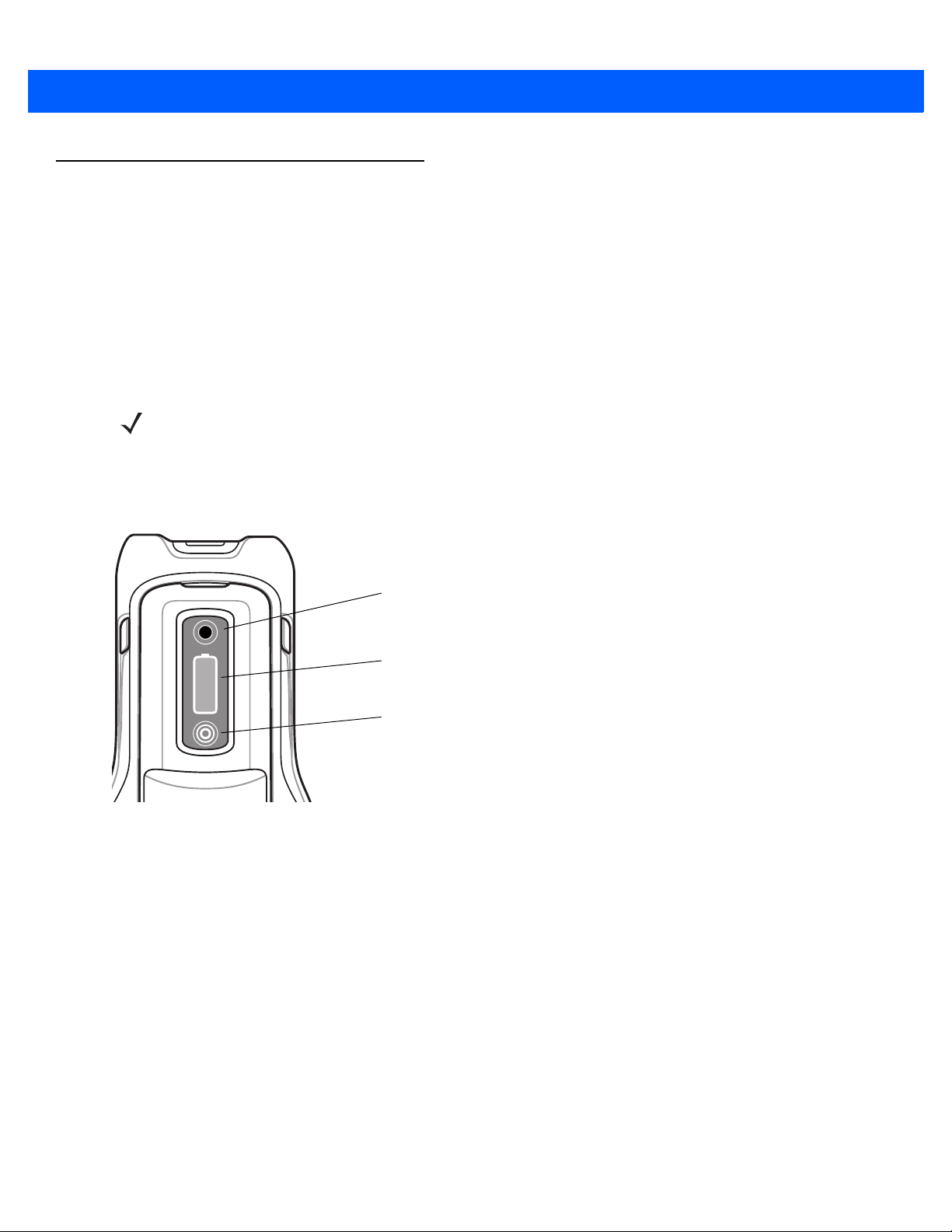
Figure 2-1
Charging Status LED indicates the charging status and health of the battery. The Charge Level Indicator indicates
an unhealthy battery and the charge level of the battery.
Battery
Page 36

2 - 2 MC9500-K Mobile Computer User Guide
Battery Health
A battery becomes unhealthy when the Battery Usage Indication reach a predefined threshold (end of usable
life).
NOTE The point at which a battery becomes unhealthy may vary depending upon the environment and charging
conditions
The Battery Usage Threshold value can be changed. See the MC9500-K Mobile Computer Integrator Guide for
more information.
When the battery becomes unhealthy, a dialog box displays on the MC9500-K. When this appears, tap Dismiss.
Replace the battery as soon as possible. The battery Charge Level indicator display an “X” when the battery
becomes unhealthy (see Figure 2-3). When charging an unhealthy battery in the MC9500-K, the Battery Status
LED blinks red.
Figure 2-2
Figure 2-3
Battery Warning Dialog Box
Unhealthy Battery Indication
Page 37
Battery Status
Battery Status LED
Charge Level Indicator
Status Button
The MC9500-K battery provides status information on the front of the battery that allows the user to make
determination on what battery to use. The battery status indications vary depending upon the mode of the battery:
•
Installed in an MC9500-K
•
In a charger
•
stand-alone.
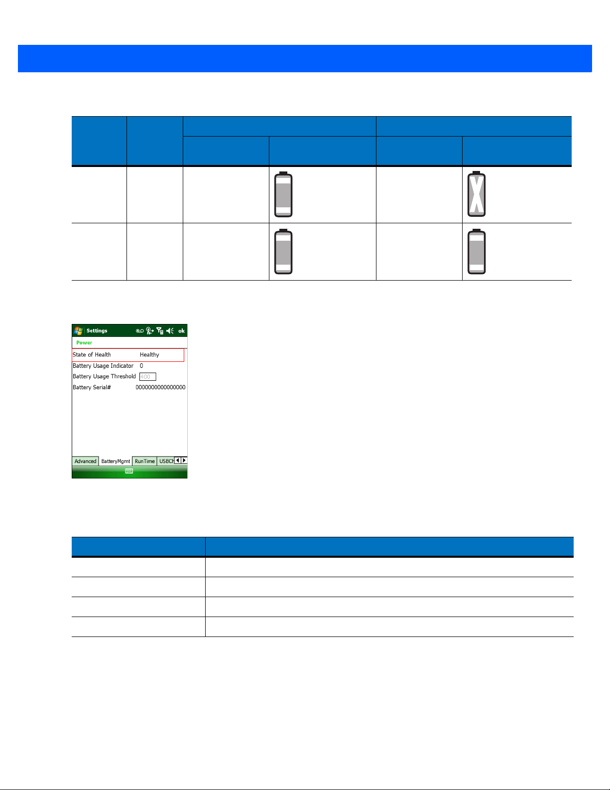
Installed in an MC9500-K
NOTE The Charge Level indicator does not display the charge level while the MC9500-K is charging.
When the battery is installed in the MC9500-K, the user can view the charge level (with Status button press) and
health of the battery (see Figure 2-4). The Battery Status LED is disabled when the battery is installed in the
MC9500-K. If the battery is unhealthy, the Charge Level indicator displays an “X” (see Figure 2-3).
Battery Management 2 - 3
Figure 2-4
Press the Status button to display the current battery charge level. It will display for five seconds and then turn off.
Table 2-1 list the Charge Level indications when the Status button is pressed.
Battery in MC9500-K
Page 38

2 - 4 MC9500-K Mobile Computer User Guide
Table 2-1
Charge Level Indicator
Charge Level
Indicator
Description
Indicates that the remaining charge is approximately
between 0% and 20%.
Indicates that the remaining charge is approximately
between 21% and 40%.
Indicates that the remaining charge is approximately
between 41% and 60%.
Indicates that the remaining charge is approximately
between 61% and 80%.
Indicates that the remaining charge is approximately
between 81% and 100%.
NOTE The battery front panel is not visible when the MC9500-K is charging in a cradle. The battery front
Table 2-2
Battery in MC9500-K
Action State
None Not
Charging
Button
Press
Not
Charging
panel is visible when charging with a charging cable. The Charge Level indicator displays a
“charging in mobile computer” indication (see Table 2-2).
Healthy Battery Unhealthy Battery
Battery Status
LED
Charge Level
Indicator
Battery Status
LED
Charge Level
Indicator
Off Off
for
Off
See
Table 2-1
on page 2-4
detailed
information.
Off
See
Table 2-1
on page 2-4
detailed
information.
for
Page 39
Battery Management 2 - 5
Table 2-2
Action State
None Charging
Button
Press
The health of the battery can also be viewed on the MC9500-K Power applet. Tap Start > Settings > Power icon >
BatteryMgmt tab.
Battery in MC9500-K (Continued)
Healthy Battery Unhealthy Battery
Battery Status
LED
Off Off
in cradle
or cable
Charging
in cradle
or cable
Off Off
Charge Level
Indicator
Battery Status
LED
Charge Level
Indicator
Figure 2-5
Table 2-3
State of Health Indicates the current state of the battery (Healthy or Unhealthy).
Battery Usage Indicator Indicates the usage of the battery.
Battery Usage Threshold Indicates the usage indicator threshold.
Battery Serial # Displays the serial number of the battery.
For information on changing the Battery Usage Threshold, refer to the MC9500-K Mobile Computer Integrator
Guide.
Power - BatteryMgmt Window
BatteryMgmt Window
Item Description
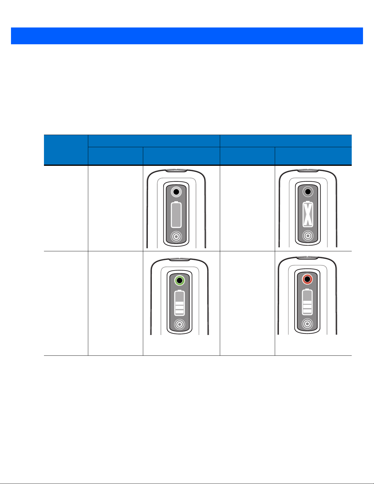
In a Charger
When the battery is in a Single Slot Battery Charger, Four Slot Battery Charger or Vehicle Battery Charger, the
battery charging status and health is indicated on the front of the battery. If the charger is not powered, the battery
acts as if it is in stand-alone mode. See Stand-alone on page 2-8 for more information.
Page 40

2 - 6 MC9500-K Mobile Computer User Guide
Battery Status LED
Charge Level Indicator
Figure 2-6
Battery in Single Slot Battery Charger
The Battery Status LED displays the current state of charging as described in Table 2-4. The Charge Level
indicator displays the charge level of a healthy battery as described in Table 2-1.
With an unhealthy battery, an “X” appears on the display. To view the charge level, press the Status button. The
display indicates the level of charge. After five seconds the display reverts to the “X” indication.
Page 41

Battery Management 2 - 7
Table 2-4
None (charger not
powered)
Charging Slow Blinking
Battery Status in Charger
Battery Status
State
LED
Off Off
Amber
(1 blink every 2
seconds)
Healthy Battery Unhealthy Battery
Charge Level
Indicator
Battery Status
LED
Slow Blinking Red
(1 blink every 2
seconds)
Charge Level
Indicator
Fully Charged Solid Green Solid Red
Charging Error
•
temperature is
too low or too
high.
•
charging has
gone on too
long without
completion
(typically eight
hours).
Fast Blinking
Amber
(2 blinks/second)
Fast Blinking
Amber
(2 blinks/second)
Page 42
2 - 8 MC9500-K Mobile Computer User Guide
Stand-alone
When the battery is not installed in an MC9500-K or a charger, the charge status and health of the battery displays
on the battery front panel. If the battery is unhealthy, an “X” appears in the Charge Level indicator. Press the Status
button to view the health and charge level of the battery. The Battery Status LED lights and the Charge Level
indicator display the charge level. After five seconds the LED turns off and the Charge Level indicator reverts to the
previous display. See Table 2-5 for Battery Status LED and Charge Level indicator descriptions.
Table 2-5
No Action Off Off
Button Press Solid Green
Battery Status - Stand-alone
Battery Status
Action
LED
Healthy Battery Unhealthy Battery
Charge Level Indicator
Battery Status
LED
Solid Red
Charge Level Indicator
See
Table 2-1 on page 2-4
for detail information.
Table 2-1 on page 2-4
See
for detail information.
Page 43

Charging the MC9500-K
CAUTION Ensure that you follow the guidelines for battery safety described in Battery Safety Guidelines on page 9-2.
The MC9500-K is equipped with a memory backup battery which automatically charges from the fully-charged
main battery. When using the MC9500-K for the first time, the backup battery requires approximately 36 hours to
fully charge. This is also true any time the backup battery is discharged, which occurs when the main battery is
removed for several hours. The backup battery retains RAM data in memory for at least 15 minutes (at room
temperature) when the MC9500-K's main battery is removed. When the MC9500-K reaches a very low battery
state, the combination of main battery and backup battery retains RAM data in memory for at least 36 hours.
To charge the battery, use either a cradle or charging cable. For cable and cradle setup and charging procedures
refer to the MC9500-K Mobile Computer Integrator Guide.
To charge the battery:
1. Connect the charging accessory to the appropriate power source. See MC9500-K Series Mobile Computer
Integrator Guide for setup information.
2. Align and hook the MC9500-K interface pocket onto the cradle’s or cable’s cleat. The MC9500-K begins
ch
arging. The Charging/Battery Status LED blinks while charging, then turns solid when fully charged (L
colo
r depends upon health of the battery). See Table 2-6 for charging indications. The 4800 mAh battery
rges in less than six hours and the 7200 mAh battery charges in less than nine hours.
cha
Battery Management 2 - 9
ED
fully
Table 2-6
None
Charging Slow Blinking Amber
Charging/Battery Status LED Indications
State
Off Off
•
battery is not charging
•
MC9500-K is not
ected correctly
conn
crad
le/cable or no
conn
ected to a powe
source.
•
cradle/cable is not
wered.
po
to the
t
r
(1 blink every 2 seconds)
Healthy Battery Unhealthy Battery
MC9500-K LED Status MC9500-K LED Status
Slow Blinking Red
(1 blink every 2 seconds)
Page 44

2 - 10 MC9500-K Mobile Computer User Guide
Table 2-6
Fully Charged Solid Green Solid Red
Charging Error
Charging/Battery Status LED Indications (Continued)
Healthy Battery Unhealthy Battery
State
•
temperature is too low or
too high.
•
charging has gone on too
long without completion
(typically eight hours for
the 4800 mAh battery).
Fast Blinking Amber
(2 blinks/second)
MC9500-K LED Status MC9500-K LED Status
Fast Blinking Amber
(2 blinks/second)
Page 45
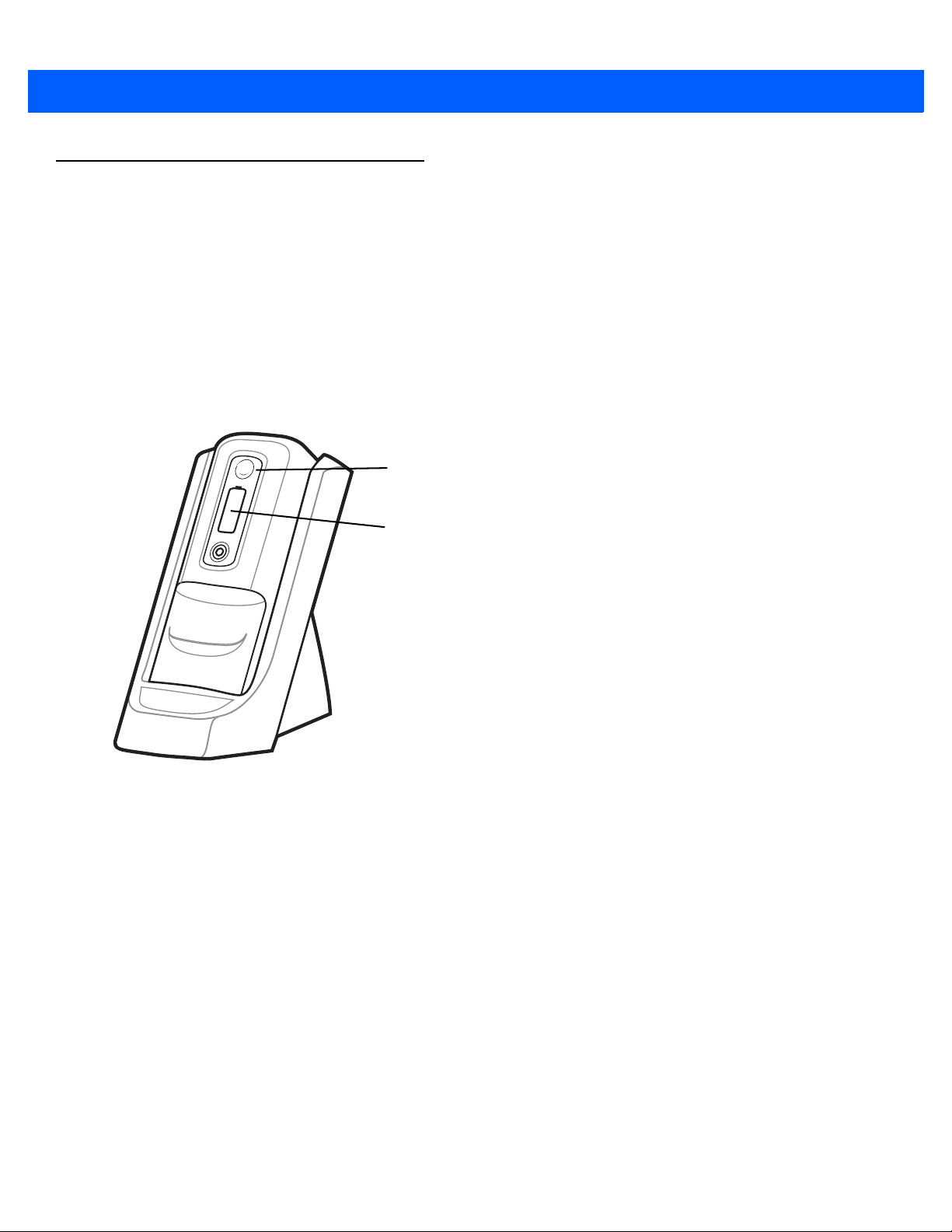
Charging a Spare Battery
Battery Status LED
Charge Level Indicator
Charge a spare battery using one of the following accessories:
•
Single Slot Battery Charger
•
Four Slot Battery Charger
•
Vehicle Battery Charger.
To charge a spare battery:
1. Ensure the charger is connected to an appropriate power source.
2. Insert the spare battery into the charger. The spare battery begins charging.
Battery Management 2 - 11
Figure 2-7
The battery charging and health status is indicated on the front of the battery. Table 2-7 lists the charging
indications.
Spare Battery in Single Slot Battery Charger
Page 46
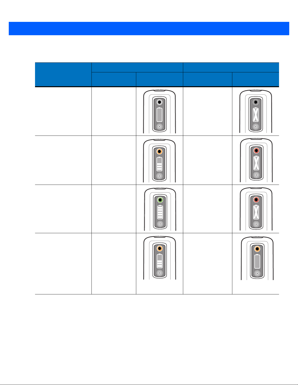
2 - 12 MC9500-K Mobile Computer User Guide
Table 2-7
None
(charger not powered)
Charging Slow Blinking
Fully Charged Solid Green Solid Red
Battery Charging Status Indications
Healthy Battery Unhealthy Battery
Battery Status
State
Off Off
Amber
(1 blink every 2
seconds)
LED
Charge Level
Indicator
Battery Status LED
Slow Blinking Red
(1 blink every 2
seconds)
Charge Level
Indicator
Charging Error
•
temperature is too
low or too high.
•
charging has
ne on too long
go
without
completion
(typically eight
urs).
ho
Fast Blinking
Amber
(2 blinks/second)
Fast Blinking Amber
(2 blinks/second)
Charging Temperature
Charge batteries in temperatures from 0°C to 40°C (32°F to 104°F). Note that charging is intelligently controlled by
the MC9500-K.
To accomplish this, for small periods of time, the MC9500-K alternately enables and disables battery charging to
keep the battery at acceptable temperatures. The MC9500-K indicates when charging is disabled due to abnormal
temperatures via its LED.
Page 47

Power Saving Techniques
Observe the following battery saving tips:
•
Leave the MC9500-K connected to AC power at all times when not in use.
•
Set the MC9500-K to turn off after a short period of non-use.
•
Set the backlight to turn off after a short period of non-use.
•
Turn off all wireless activities when not in use.
Changing the Power Settings
To set the MC9500-K to turn off after a short period of non-use:
1. Ta p Start > Settings > System tab > Power icon > Advanced tab.
2. Select the On battery power: Turn off device if not used for check box and select a value from the
drop-down list.
3. Select ok.
Battery Management 2 - 13
Changing the Backlight Settings
To change the backlight settings in order to conserve more battery power:
1. Ta p Start > Settings > System tab > Backlight icon > Battery Power tab.
2. Select the Disable backlight if device is not used for check box and select a value from the drop-down list.
3. Select the Brightness tab.
4. Tap the Disable backlight check box to turn off the display backlight, or use the slider to set a low value for the
backlight.
5. Select ok.
Changing the Keypad Backlight Settings
To change the keypad backlight settings in order to conserve more battery power:
1. Ta p Start > Settings > System tab > Keylight icon > Battery Power tab.
2. Select the On battery power: Disable keylight if device if not used for check box and select a value from
the drop-down list.
3. Select the Advanced tab.
4. Tap the Disable keylight check box to turn off the keypad backlight.
5. Select ok.
Turning Off the Radios
Windows Mobile 6 devices include Wireless Manager, which provides a simple method of enabling, disabling, and
configuring all the device’s wireless capabilities in one place.
Page 48

2 - 14 MC9500-K Mobile Computer User Guide
Connectivity icon
To open Wireless Manager, tap the Connectivity icon or tap Wireless Manager on the Today screen.
Figure 2-8
Opening Wireless Manager
Select Wireless Manager.
Figure 2-9
Wireless Manager Window
NOTE Wireless connection options vary depending upon configurations.
To enable or disable a wireless connection, tap the specific button.
To enable or disable all wireless connections, tap and hold the All button.
To configure settings for a connection, tap Menu.
Page 49

Battery Management 2 - 15
Figure 2-10
Wireless Manager Menu
Page 50

2 - 16 MC9500-K Mobile Computer User Guide
Page 51

Chapter 3 Using the MC9500-K
Decode LED
Battery Status
LED
WAN Radio
Status LED
Introduction
This chapter explains the indicators, buttons, status icons, and controls on the MC9500-K, and provides basic
instructions for using the device.
LED Indicators
The MC9500-K has three LED indicators. The Decode LED indicates scanning status. The Battery Status LED
indicates battery charging and health status.The WAN Radio Status LED indicates WAN radio status. Table 3-1
describes the LED indications.
Figure 3-1
Table 3-1
Decode LED
Solid Green Successful decode/capture.
Solid Red Scanning/imaging in process.
Blinks Red After the Power button is pressed, turns on and then off to
LED Indicators
LED Indications
LED State Indication
indicate that the battery can be removed.
Page 52

3 - 2 MC9500-K Mobile Computer User Guide
Table 3-1
Off Not enabled.
Battery Status LED
Off Indicates that the:
Slow Blinking Amber
(1 blink every 2 seconds)
Slow Blinking Red
(1 blink every 2 seconds)
Solid Green Indicates that a healthy battery is fully charged.
Solid Red Indicates that an unhealthy battery is fully charged.
Fast Blinking Amber
(2 blinks/second)
LED Indications (Continued)
LED State Indication
•
battery is not charging
•
MC9500-K is not connected correctly to the cradle
or not connected to a power source.
•
cradle is not powered.
Indicates that a healthy battery is charging.
Indicates that an unhealthy battery is charging.
Indicates a charging error, e.g.:
•
temperature is too low or too high.
•
charging has gone on too long without completion
(typic
ally eight hours).
Single Blink Amber (when Power button pressed) Battery depleted.
Blinking Amber (when Power button pressed) Battery over-temperature condition.
WAN Radio Status LED (MC9596 or MC9598 only)
Slow Blinking Green WAN activity.
Off No WAN activity.
NOTE For information about scanning/decoding, see Chapter 4, Data Capture. For information about WAN radio
status and settings, see Chapter 5, Using the Phone, or refer to the MC9500-K Mobile Computer Integrator
Guide.
Page 53
Resetting the MC9500-K
There are two reset functions, warm boot and cold boot. A warm boot restarts the MC9500-K by closing all running
programs. A cold boot also restarts the MC9500-K, and also initializes some drivers. Data saved in flash memory
or a memory card is not lost.
If the MC9500-K is not functioning properly, perform a warm boot first. If the MC9500-K still does not respond,
perform a cold boot.
Performing a Warm Boot
Hold down the red Power button for approximately five seconds. As soon as the MC9500-K starts to boot release
the Power button.
Performing a Cold Boot
To perform a cold boot, simultaneously press the red Power button and the 1 and 9 keys.
Using the MC9500-K 3 - 3
Waking the MC9500-K
The wake-up conditions define what actions wake up the mobile computer after it has gone into suspend mode.
The mobile computer can go into suspend mode by either pressing the Power button or automatically by Control
Panel time-out settings. These settings are configurable and the factory default settings are shown in Table 3-2 are
subject to change/update.Tap Start > Setting > System > Power icon > Wakeup tab to configure these settings.
Table 3-2
AC power is applied. No Yes
Mobile computer is inserted into a cradle. No Yes
Mobile computer is removed from a cradle. No Yes
Mobile computer is connected to a USB device. Yes Yes
A key is pressed. No Yes
The scan triggered is pressed. No Yes
The screen is touched. No No
Bluetooth communication Yes Yes
On motion No No
Wake-up Default Settings
Condition for Wake-up Power Button Automatic Time-out
Incoming phone call (MC9596 and MC9598 only) Yes Yes
Page 54

3 - 4 MC9500-K Mobile Computer User Guide
Device Unlocked Icon Device Locked Icon
Figure 3-2
Power Settings Wakeup Tab
Locking the MC9500-K
NOTE On devices with Windows Mobile 6.5.3, the locking feature is different. See Locking the MC9500-K on page
D-15 for more information.
You can lock the MC9500-K by disabling key presses and screen tap or by requiring a password.
Keypad Locking
Locking the MC9500-K turns off keyboard and touch screen functionality. This is helpful when the MC9500-K is
turned on and you want to prevent accidental key presses.
To lock the device, tap the Device unlocked icon. The icon changes to locked.
Figure 3-3
To unlock the device and free it for use, tap Unlock.
Device Locked/Unlocked Icons
Page 55
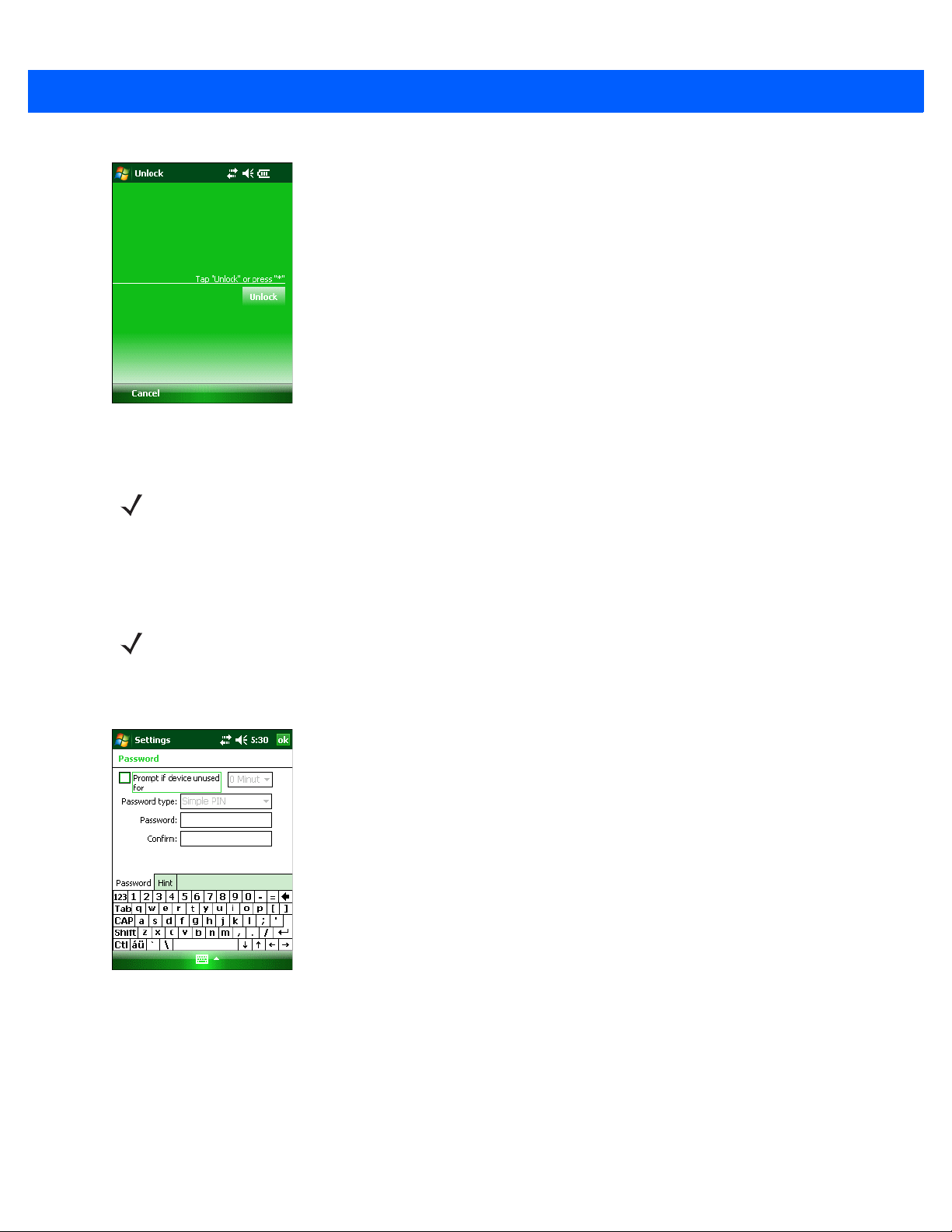
Using the MC9500-K 3 - 5
Figure 3-4
Unlock Device Window
Ta p Unlock on the Unlock window.
NOTE You can make emergency calls even when the MC9596-K or MC9598-K is locked. See Making an Emergency
Call on page 5-10 for more information.
Password Locking
Use the Password window to set a password to disable unauthorized access to the MC9500-K.
NOTE If the device is configured to connect to a network, use a strong (difficult to figure out) password
to help protect network security. Password cracking tools continue to improve and the
computers used to crack passwords are more powerful than ever.
1. Ta p Start > Settings > Personal tab > Lock icon > Password tab.
Figure 3-5
2. Select Prompt if device unused for check box to enable password protection.
3. From the drop-down list, select a time value for the protection to take affect after non-use.
4. From the Password type: drop-down list, select either Simple PIN or Strong alphanumeric.
5. For a simple password, enter a four-digit password in the Password field.
Password Window - Password Tab
For a stronger password:
Page 56

3 - 6 MC9500-K Mobile Computer User Guide
a. Enter a seven character password in the Password: field. A strong password must contain at least seven
cha
racters and contain at least three of the following: uppercase and lowercase letters, numerals, an
p
unctuation.
b. Re-enter the password in the Confirm: field.
6. Ta p ok.
7. To set a hint to remember the password, tap the Hint tab.
d
Figure 3-6
8. In the text box, enter a hint for a password reminder.
9. Ta p ok.
Password Window - Hint Tab
When the MC9500-K is not used for a period of time and the user tries to access the device, the Password window
appears.
Figure 3-7
Enter Password Windows
Enter the password to un-lock the device.
Ta p Unlock.
Page 57

Keypads
The MC9500-K offers four types modular keypad configurations. See Appendix C, Keypads for keypad
functionality.
Function Buttons
The MC9500-K’s buttons perform certain functions.
•
Power: Press the red Power button to place the MC9500-K into suspend mode or wake from suspend mode.
Also use the Power bu
MC9
500-K on page 3-3.
•
Scan/Action: Press to scan bar codes or capture images. See Chapter 4, Data Capture.
, press to open an application or perform a function. See the Microsoft
Or
Guide to
•
Volume Up/Down: Press to increase or decrease the MC9500-K’s volume.
set an application to open.
Using the MC9500-K 3 - 7
tton to reset the MC9500-K by performing a warm or cold boot. See Resettin
®
Applications for Mobile 6 User
g the
Stylus
•
Action: Press to open an application or perform a function. See the Microsoft® Applications for Windows
Mobile 6 User Guide to
•
Green Key: Press to open the Phone Dialer window or answer an incoming call or place a call on hold.
•
Red Key: Press to end a call.
•
Function Keys: Programmable functions for performing specific applications.
• F1 - Left soft key
• F2 - Right soft key
• F3 - Talk (MC9596/8 only)
• F4 - End Call (MC9596/8 only)
• F5 - Refreshes the screen in Internet Explorer and File Explorer.
• F6 - Volume Up.
Use the MC9500-K stylus to select items and enter information. The stylus functions as a mouse.
•
Tap: Touch the screen once with the stylus to press option buttons and open menu items.
•
Tap and Hold: Tap and hold the stylus on an item to see a list of actions available for that item. On the pop-up
nu that appears, tap the action to perform.
me
set an application to open.
•
Drag: Hold the stylus on the screen and drag across the screen to select text and images. Drag in a list to
selec
t multiple items.
CAUTION To prevent damage to the screen, do not use any device other than the Zebra-provided stylus.
Page 58

3 - 8 MC9500-K Mobile Computer User Guide
Single-hand Method Two-hand Method
Entering Data
When entering data on the keypad, use either the single-hand method or the two-hand method as shown in Figure
3-8.
Figure 3-8
Entering Data on the Keypad
Page 59

Interactive Sensor Technology
This section describes the functionality of the Interactive Sensor Technology (IST) feature on the MC9500-K.
The IST supports the following features.
•
Power Management – manage power by configuring IST to control switching on/off the backlight, control
spend mode of the MC9500-K by monitoring motion and orientation.
su
•
Display Orientation – switch the screen orientation to either landscape or portrait depending on the
500-K orientation.
MC9
•
Free Fall Detection – monitors free fall duration and records the time and type of the drop event.
Power Management
The MC9500-K orientation and motion sensitive data can be used as an indicator of MC9500-K usage and can be
used to manage the battery power of the mobile computer. For example, IST can be configured to control the
backlight on and off functionality or go into suspend according to a user gesture by placing screen facing down. It
can also be used to keep the MC9500-K active while it is in movement to prevent it from quickly going into suspend
mode while in use.
Using the MC9500-K 3 - 9
Display Orientation
The screen can be rotated between portrait and landscape modes automatically, depending on the physical
orientation of the MC9500-K. For example, if the MC9500-K is rotated 90° counterclockwise, IST rotates the
display counterclockwise 90° so that the screen display appears correct.
This functionality is achieved by monitoring screen angle and rotating the display to counter any changes. IST only
rotates the screen in multiples of 90°.
Figure 3-9
Display Orientation
Page 60
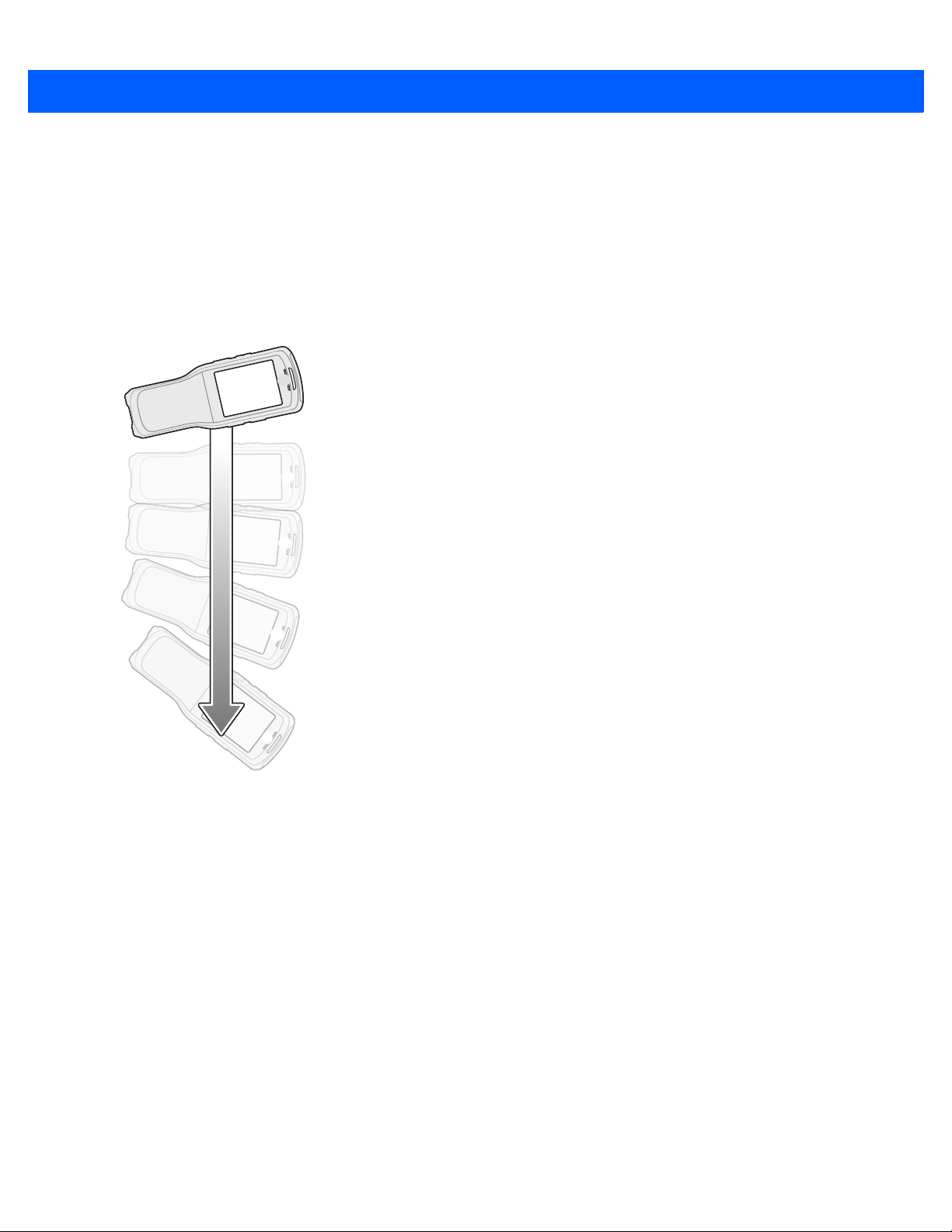
3 - 10 MC9500-K Mobile Computer User Guide
Free Fall Detection
IST continuously monitors gravitational force on the MC9500-K according to its current position. When the
MC9500-K free falls, IST detects the absence of gravitational force and records the event data if it detects a free
fall more than 450 ms, which may indicates nearly a one meter drop. This data can be used as an indicator of
potential abuse or misuse.
IST features a log for recording the free fall events. This log records the date, time and the time period of the free
fall.
Figure 3-10
Free Fall Detection
Page 61
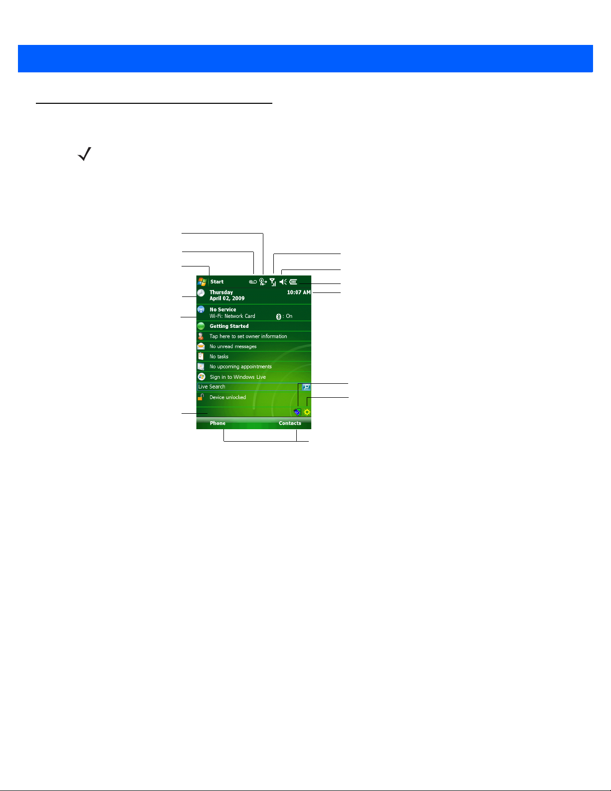
Today Screen
Open the Start Menu
Adjust volume
Change the date and time
Soft Keys
Battery Status
Command Bar
WAN Signal Strength
Turn on or off radios
Change the date and time, set up the alarm, and more
IST Configuration
Wireless Applications
Notification
Connectivity
NOTE On devices with Windows Mobile 6.5.3, the Today screen has changed. See Home Screen on page D-1 for
The Today screen displays important information, such as upcoming appointments and status indicators. Tap a
section on the screen to open the associated program. Alternatively, tap Start > Today to display the Today
screen.
Using the MC9500-K 3 - 11
more information.
Figure 3-11
To customize the Today screen, tap Start > Settings > Today icon. Use the Appearance tab to customize the
background and the Items tab to change the list and order of items that appear on the screen.
Today Screen
Page 62

3 - 12 MC9500-K Mobile Computer User Guide
Status Icons
NOTE On devices with Windows Mobile 6.5.3,the functionality of the Status bar has changed. See Status Bar on
page D-5 for more information.
The Navigation bar at the top of the screen can contain the status icons listed in Table 3-3.
Table 3-3
Icon Function Description
Status Icons
Notification Backup Battery Low.
Notification that one or more instant messages were received.
Notification that one or more e-mail/text messages were received.
Notification that one or more voice messages were received.
There are more notification icons than can be displayed. Tap to display
remaining icons.
Indicates a reminder of an upcoming calendar event.
Connectivity Connection is active.
Connection is not active.
Synchronization is occurring.
Wi-Fi available.
Wi-Fi in use.
HSDPA available. (MC9596 only)
HSDPA connecting. (MC9596 only)
3G available. (MC9596 only)
3G connecting. (MC9596 only)
GPRS available. (MC9596 only)
GPRS connecting. (MC9596 only)
EGPRS available. (MC9596 only)
EGPRS connecting. (MC9596 only)
EVDO connecting. (MC9598 only)
1xRTT available. (MC9598 only)
EVDO Rev. 0 available. (MC9598 only)
EVDO Rev. A available. (MC9598 only)
Dormant State - no data transmission during a 1x or EVDO connection.
(MC9598 only)
Page 63

Using the MC9500-K 3 - 13
Table 3-3
Icon Function Description
Status Icons (Continued)
WAN Call missed.
Dialing while no SIM card is installed.
Voice call in progress.
Calls are forwarded.
Call on hold.
Speakerphone is on.
Antenna/signal icon: wireless on/good signal.
Antenna/signal icon: wireless off.
Antenna/signal icon: no service or searching.
HSDPA in use. (MC9596 only)
3G in use. (MC9596 only)
GPRS in use. (MC9596 only)
EGPRS in use. (MC9596 only)
EVDO in use. (MC9598 only)
Roaming.
SIM Card not installed. (MC9596 only)
Speaker All sounds are on.
All sounds are off.
Vibrate is on.
Battery Main battery is charging.
Battery power completely depleted.
Main battery is low.
Main battery level.
Time and Next
Appointment
Displays current time in analog or digital format.
Page 64
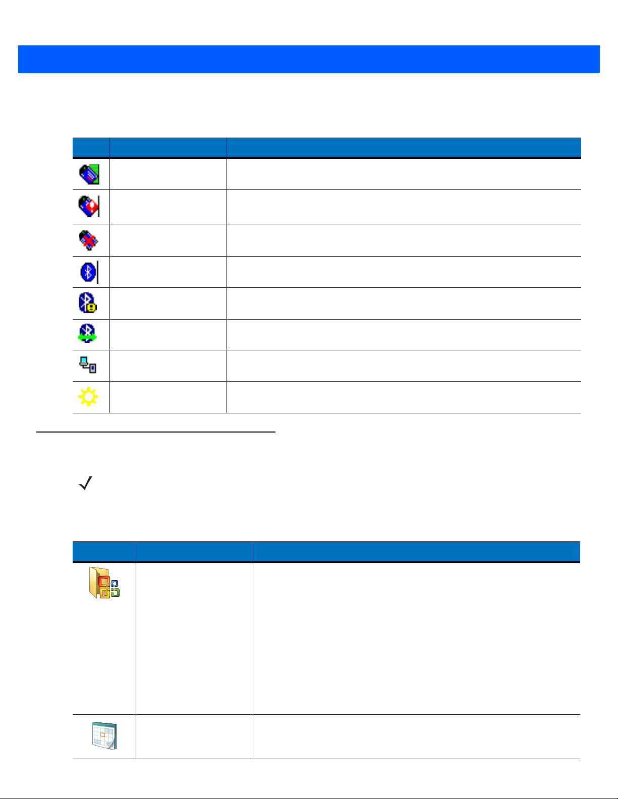
3 - 14 MC9500-K Mobile Computer User Guide
The Command Bar at the bottom of the screen can contain the application icons listed in Table 3-4.
Table 3-4
Command Bar Icons
Icon Description
Wireless connection
status
Out-of-network range
(not associated)
No wireless LAN
network card detected
Bluetooth Enabled Indicates the Bluetooth radio is on.
Bluetooth Disabled Indicates the Bluetooth radio is off.
Bluetooth Connection Indicates the Bluetooth radio is connected to another Bluetooth device.
ActiveSync Indicates an active serial connection between the MC9500-K and the host
IST icon Opens the IST settings menu.
Indicates WLAN signal strength.
Indicates no wireless LAN network connection. Notify the network
administrator.
Indicates Wireless LAN disabled or radio disabled. Notify the network
administrator.
(Displays only if the StoneStreet One Bluetooth stack is enabled)
(Displays only if the StoneStreet One Bluetooth stack is enabled)
(Displays only if the StoneStreet One Bluetooth stack is enabled)
computer.
Programs
Table 3-5 lists the default programs on the Start menu.
Table 3-5
NOTE On devices with Windows Mobile 6.5.3, the functionality of the Start Menu has changed. See Home Screen on
page D-1 for more information.
Programs in the Start Menu
Icon Name Description
Office Mobile
Use the complete suite of Microsoft
®
Office applications for your mobile
device.
Excel Mobile - Create new workbooks or view and edit Microsoft
®
Excel
workbooks.
OneNote Mobile - Create new notes or view existing notes.
PowerPoint Mobile - View Microsoft
®
PowerPoint® slides and
presentations.
®
Word Mobile - Create, view, and edit Microsoft
Word documents.
Refer to the Microsoft Applications for Windows Mobile 6 User Guide
for more information.
Calendar Keep track of appointments and create meeting requests. Refer to the
Microsoft Applications for Windows Mobile 6 User Guide for more
information.
®
Page 65

Using the MC9500-K 3 - 15
Table 3-5
Table 3-6 lists programs that are listed in the Programs window.
Table 3-6
Programs in the Start Menu (Continued)
Icon Name Description
Contacts Keep track of friends and colleagues. Refer to the Microsoft
Applications for Windows Mobile 6 User Guide for more information.
Internet Explorer Mobile Browse Web and WAP sites as well as download new programs and
files from the Internet. Refer to the Microsoft Applications for Windows
Mobile 6 User Guide for more information.
Messaging Send and receive e-mail and text messages. Refer to the Microsoft
Applications for Windows Mobile 6 User Guide for more information.
Phone Make and receive calls, switch between calls, and set up conference
calling. See Chapter 5, Using the Phone for more information. MC9596
and MC9598 only.
Help See Help topics for the current screen or program.
Programs in Program Window
Icon Name Description
ActiveSync Synchronize information between the MC9500-K and a host computer
or the Exchange Server. Refer to the MC9500-K Series Mobile
Computer Integrator Guide for more information.
AirBEAM Client Allows specially designed software packages to be transferred between
a host server and the MC9500-K. Refer to the MC9500-K Series Mobile
Computer Integrator Guide for more information.
BT Information Displays information about the Bluetooth radio. See Chapter 7, Using
Bluetooth.
BTExplorer Manages StoneStreet One Bluetooth connections. Refer to the
MC9500-K Series Mobile Computer Integrator Guide for more
information. Appears only if the StoneStreet One Bluetooth stack is
enabled.
Calculator Perform basic arithmetic and calculations, such as addition,
subtraction, multiplication, and division. Refer to the Microsoft
Applications for Windows Mobile 6 User Guide for more information.
File Explorer Organize and manage files on your device. Refer to the Microsoft
Applications for Windows Mobile 6 User Guide for more information.
Getting Started Provides quick links for setting the devices clock, setting up e-mail,
setting a device password, setting a background image and transferring
music. Refer to the Microsoft Applications for Windows Mobile 6 User
Guide for more information.
Page 66

3 - 16 MC9500-K Mobile Computer User Guide
Table 3-6
Programs in Program Window (Continued)
Icon Name Description
Internet Sharing Connect a notebook computer to the Internet using the MC9500-K's
data connection.
Messenger Use this mobile version of Windows Live Messenger. Refer to the
Microsoft Applications for Windows Mobile 6 User Guide for more
information.
DEMO Provides a web link to Zebra’s featured demos for the MC9500-K.
Modem Link
MSP Agent Interacts with MSP agents to collect monitoring and asset information
Notes Create handwritten or typed notes, drawings, and voice recordings.
Enables the MC9500-K to be used as a modem.
to enable the configuration, provisioning, monitoring and
troubleshooting of the MC9500-K. Refer to the Mobility Services
Platform User Guide for more information.
Refer to the Microsoft Applications for Windows Mobile 6 User Guide
for more information.
Pictures & Videos View and manage pictures, animated GIFs, and video files. Refer to the
Microsoft Applications for Windows Mobile 6 User Guide for more
information.
Rapid Deployment
Client
Remote Desktop
Mobile
Search Search contacts, data, and other information on your MC9500-K. Refer
SIM Toolkit Manage the contacts that are stored on your SIM card. Copy SIM
SMS Staging
Task Manager Enables viewing of memory and CPU allocations and stops running
Facilitates software downloads from a Mobility Services Platform Console
FTP server to the MC9500-K.
Integrator Guide for more information.
Log onto Windows NT server type computers and use all of the programs
that are available on that computer from the MC9500-K.
to the Microsoft Applications for Windows Mobile 6 User Guide for more
information.
contents to Contacts on the MC9500-K. See Chapter 5, Using the
Phone for more information. MC9596 and MC9598 only.
SMS Staging - Receives and processes SMS messages from an MSP
Server and allows the user to stage an MC9500-K based on them.
Requires the purchase of an MSP client license per device.
processes. Refer to the Microsoft Applications for Windows Mobile 6
User Guide for more information.
Refer to the MC9500-K Mobile Computer
Page 67
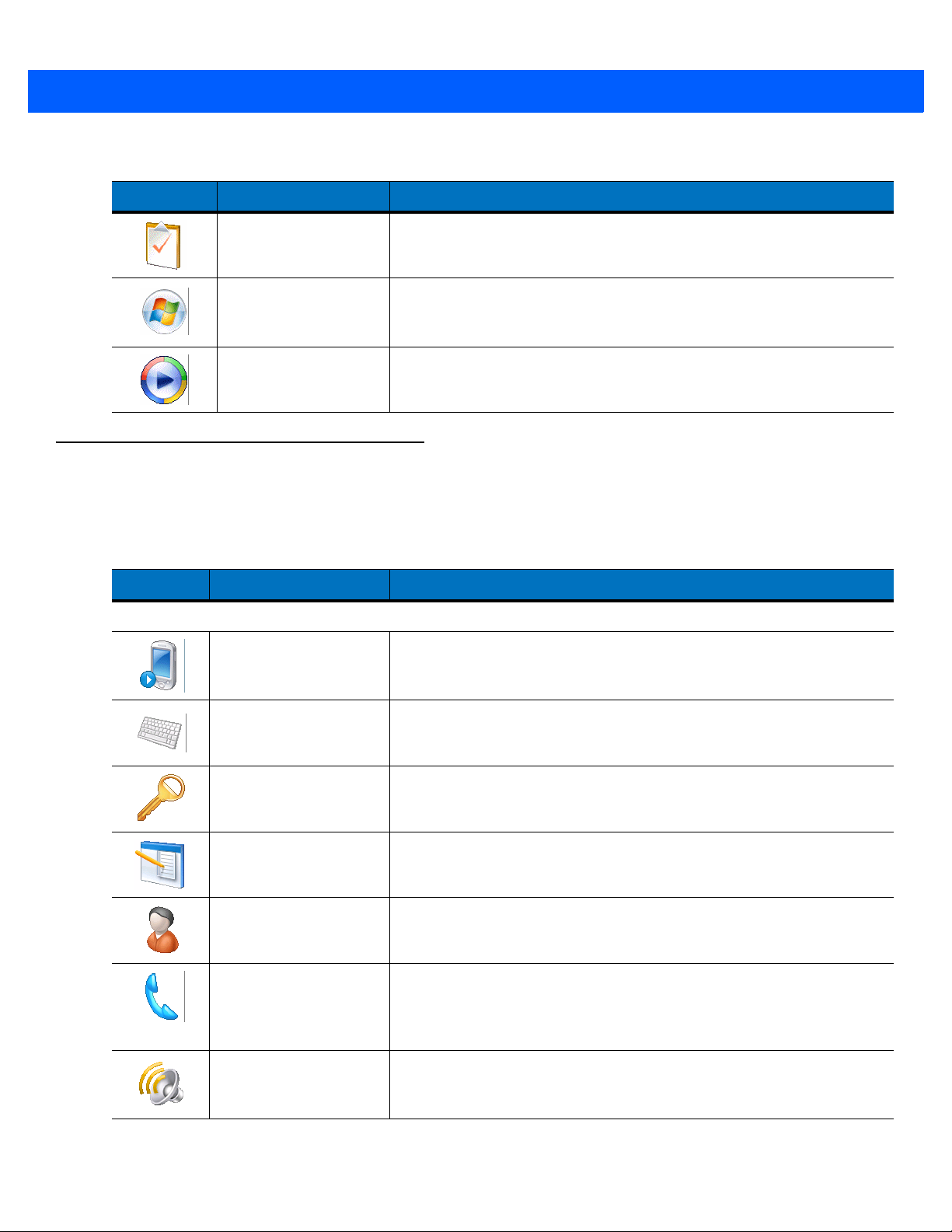
Using the MC9500-K 3 - 17
Table 3-6
Settings
Table 3-7 lists control applications pre installed on the MC9500-K. Tap Start > Settings to open the Settings
window.
Table 3-7
Personal Tab
Programs in Program Window (Continued)
Icon Name Description
Tasks Keep track of your tasks. Refer to the Microsoft Applications for
Windows Mobile 6 User Guide for more information.
Windows Live Use this mobile version of Windows Live™ to find information on the
web. Refer to the Microsoft Applications for Windows Mobile 6 User
Guide for more information.
Windows Media Play back audio and video files. Refer to the Microsoft Applications for
Windows Mobile 6 User Guide for more information.
Settings in the Setting Window
Icon Name Description
Buttons Assign a program to a button. Refer to the Microsoft Applications for
Windows Mobile 6 User Guide for more information.
Input Set options for each of the input methods. Refer to the Microsoft
Applications for Windows Mobile 6 User Guide for more information.
Lock Set a password for the MC9500-K.
Menus Set what programs appear in the Start menu. Refer to the Microsoft
Applications for Windows Mobile 6 User Guide for more information.
Owner Information Enter personal information on the MC9500-K. Refer to the Microsoft
Applications for Windows Mobile 6 User Guide for more information.
Phone Make and receive calls, switch between calls, and set up conference
calling. See Chapter 5, Using the Phone for more information. See
Chapter 5, Using the Phone for more information. MC9596 and
MC9598 only.
Sounds & Notifications Enable sounds for events, notifications, and more, and set the type of
notification for different events. Refer to the Microsoft Applications for
Windows Mobile 6 User Guide for more information.
Page 68
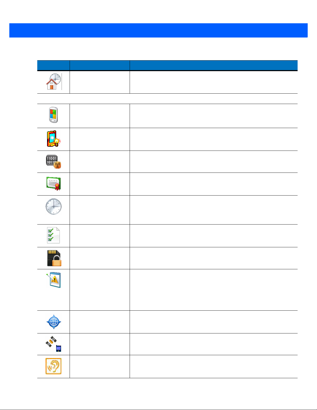
3 - 18 MC9500-K Mobile Computer User Guide
Table 3-7
Settings in the Setting Window (Continued)
Icon Name Description
Today Customize the appearance and the information to be displayed on the
Today screen. Refer to the Microsoft Applications for Windows Mobile 6
User Guide for more information.
System Tab
About
View basic information such as the Windows Mobile
of processor used on the MC9500-K. Refer to the Microsoft
Applications for Windows Mobile 6 User Guide for more information.
Backlight Set the display backlight time-out and adjust brightness. Refer to the
Microsoft Applications for Windows Mobile 6 User Guide for more
information.
Broadband Setting View radio information and select carrier. MC959B only. Refer to the
MC9500-K Mobile Computer Integrator Guide for more information.
Certificates See information about certificates installed on the MC9500-K. Refer to
the Microsoft Applications for Windows Mobile 6 User Guide for more
information.
Clock & Alarms Set the device clock to the date and time of your locale or to a visiting
time zone when you’re traveling. Alarms can also be set at specified
days and times of a week. Refer to the Microsoft Applications for
Windows Mobile 6 User Guide for more information.
®
version and type
Customer Feedback Submit feedback on the Windows Mobile 6.1 software. Refer to the
Microsoft Applications for Windows Mobile 6 User Guide for more
information.
Encryption Allow files on a storage card to be encrypted. Encrypted files are
readable only on your device.
Error Reporting Enable or disable the device's error reporting function. When this
function is enabled and a program error occurs, technical data about
the state of the program and your computer is logged in a text file and
delivered to Microsoft's technical support if you choose to send it. Refer
to the Microsoft Applications for Windows Mobile 6 User Guide for more
information.
External GPS Set the appropriate GPS communication ports, if required. You may
need to do this when there are programs on your device that access
GPS data or you have connected a GPS receiver to the MC9500-K.
GPS Setup View GPS & A-GPS SUPL information.
HAC Settings Enable or disable the Hearing Aid Compatibility (HAC) feature. See
Chapter 5, Using the Phone for more information. MC9596 and
MC9598 only.
Page 69

Using the MC9500-K 3 - 19
Table 3-7
Settings in the Setting Window (Continued)
Icon Name Description
IST Settings Set the appropriate setting for configuring the device’s Interactive
Sensor Technology. See Interactive Sensor Technology on page 3-9 for
more information
Keylight Set the keypad backlight time-out. Refer to the Microsoft Applications
for Windows Mobile 6 User Guide for more information.
Managed Programs Lists applications that have been installed remotely by your system
administrator. Refer to the Microsoft Applications for Windows Mobile 6
User Guide for more information.
Memory Check the device memory allocation status and memory card
information. Refer to the Microsoft Applications for Windows Mobile 6
User Guide for more information.
Phone Info Displays the phone version information. MC9596 and MC9598 only.
Power Check battery power and set the time-out for turning off the display to
conserve battery power. Refer to the Microsoft Applications for
Windows Mobile 6 User Guide for more information.
Regional Settings Set the regional configuration to use, including the format for displaying
Remove Programs Remove programs that you installed on the MC9500-K. Refer to the
Screen Change the screen orientation, re-calibrate the screen, and change the
System Info Displays the MC9500-K’s software and hardware information. Refer to
Task Manager Enables viewing of memory and CPU allocations and stops running
Windows Update Link to Microsoft's web site and update Windows Mobile® on your
Connections Tab
numbers, currency, date, and time on the MC9500-K. Refer to the
Microsoft Applications for Windows Mobile 6 User Guide for more
information.
Microsoft Applications for Windows Mobile 6 User Guide for more
information.
screen text size. Refer to the Microsoft Applications for Windows
Mobile 6 User Guide for more information.
the Microsoft Applications for Windows Mobile 6 User Guide for more
information.
processes. Refer to the Microsoft Applications for Windows Mobile 6
User Guide for more information.
device with the latest security patches or fixes. Do not use. Obtain
updates from Zebra. Refer to the Microsoft Applications for Windows
Mobile 6 User Guide for more information.
Beam Set the device to receive incoming IrDA beams.
Page 70

3 - 20 MC9500-K Mobile Computer User Guide
Table 3-7
Settings in the Setting Window (Continued)
Icon Name Description
Bluetooth Enables Bluetooth radio and functionality. See Chapter 7, Using
Bluetooth for more information.
Connections Set up one or more types of modem connections for your device, such
as phone dial-up, GPRS, Bluetooth, and more, so that your device can
connect to the Internet or a private local network.
Domain Enroll Make your device an AD domain member for device management and
security. Refer to the Microsoft Applications for Windows Mobile 6 User
Guide for more information.
USB to PC Enables or disables the enhanced network connectivity. Refer to the
Microsoft Applications for Windows Mobile 6 User Guide for more
information.
Wi-Fi Setup wireless network connection and customize settings. Refer to the
Microsoft Applications for Windows Mobile 6 User Guide for more
information.
Wireless Manager Enables or disables the MC9500-K’s wireless radios and customizes
Wi-Fi and Bluetooth and Phone settings.
Adjusting Volume
To adjust the system volume using the Speaker icon in the navigation bar:
1. Tap the Speaker icon. The Volum e dialog box appears.
Figure 3-12
2. Tap and move the slide bar to adjust the volume.
3. Select the On or Off radio button to turn the volume on or off.
You can also adjust the system volume using the Sounds & Notifications window, or use the Up/Down button on
the side of the MC9500-K.
Volume Dialog Box
Page 71

Battery Status Indications
Battery icons appear on the navigation bar indicating the battery power level. When the main battery power falls
below a predetermined level the icon indicates the status and a battery dialog box appears indicating the status of
the battery.
Using the MC9500-K 3 - 21
Figure 3-13
The Battery icon always appears in the navigation bar when the Today screen is visible. The icon indicates the
battery power level. The message displays until the Dismiss button is pressed.
Figure 3-14
Also view the battery status using the Power window. Either:
•
•
Battery Status Dialog Box
Battery Icon on the Title Bar
Tap the Battery icon
Ta p Start > Settings > System tab > Power icon.
Figure 3-15
Settings Power Window
Battery Reserve Options
If the charge of the battery reaches a critical threshold, the MC9500-K shuts down. This threshold can be changed
but affects the amount of time that data can be retained.
Page 72
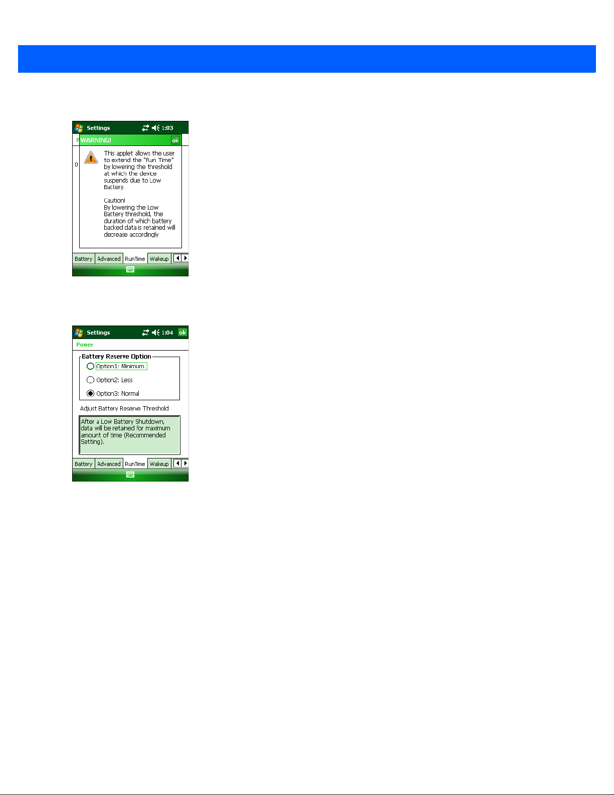
3 - 22 MC9500-K Mobile Computer User Guide
1. Ta p Start > Settings > System tab > Power icon > RunTime tab. A warning message appears.
Figure 3-16
2. Read the warning message and tap ok.
Figure 3-17
3. Select one of the Battery Reserve Options.
•
•
Warning Message
RunTime Tab
Option 1: Minimum - After a low battery shutdown, data will be retained for minimum amount of time.
Battery should be replaced immediately to avoid data loss.
Option 2: Less - After a low battery shutdown, data will be retained for less than normal amount of time.
•
Option 3: Normal - After a low battery shutdown, data will be retained for maximum amount of time.
4. Ta p ok.
Main Battery Temperature Notifications
The temperature notification system implements three levels of notification when the temperature within the battery
exceeds specific temperature thresholds:
•
Level 1: Temperature Watch; this level is similar to main battery low warning. It indicates that the battery
temperature has reached the first threshold level. The user should move to an environment within proper
operating temperature.
•
Level 2: Temperature Warning; this level is similar to main battery very low warning. It indicates the battery
temperature has reached the second threshold level. The user should stop using the MC9500-K.
Page 73

Using the MC9500-K 3 - 23
•
Level 3: Temperature Error; this level indicates the battery has reached an unusable temperature threshold
and immediately suspends the MC9500-K. This level does not have any graphical notification associated
with it.
Figure 3-18
Figure 3-19
Main Battery Temperature Watch Dialog Box
Main Battery Temperature Warning Dialog Box
NOTE The Temperature Warning dialog box remains visible until you tap Hide.
Using Voice-Over-IP
The MC9500-K supports Voice over IP over WLAN (VoWLAN) using Zebra or third party voice clients. The
MC9500-K can communicate using VoIP either using the MC9500-K supports several audio outputs, including
back speaker phone, front receiver or handset, and Bluetooth headset.
It is recommended that the wireless network use the 802.11a (5 GHz) band for voice applications. Using the 5 GHz
band avoids some noise sources that may occur on the 802.11b/g (2.4 GHz) band due to wireless interference.
When using a Bluetooth headset with the MC9500-K and VoWLAN, it is required to use the Bluetooth Headset
profile instead of Hands-free profile. Use the buttons on the MC9500-K to answer and end calls. See Chapter 7,
Using Bluetooth for information on setting up a Bluetooth Headset Profile.
Page 74

3 - 24 MC9500-K Mobile Computer User Guide
Infrared Connection
Using infrared, you can enable short-range file exchange between your MC9500-K and another IrDA device.
Exchanging Files using IR Connection
Ensure that the IrDA function on both the MC9500-K and the other device are enabled.
To send files via IrDA connection:
1. Switch to the program where you created the item you want to send and locate the item in the list.
NOTE Do not cover or block the IrDA window.
2. Align the IrDA port of the MC9500-K with that of the IrDA device so that they are unobstructed and within a
close range.
Figure 3-20
3. Tap and hold the item, then tap Beam [type of item] on the pop-up menu.
4. Tap the device that you want to send the file to.
Align MC9500-K with IrDA Device
Page 75

Using the MC9500-K 3 - 25
Figure 3-21
To receive files via IrDA connection:
1. Align the IrDA port of the MC9500-K with that of the other IrDA device so that they are unobstructed and within
a close range.
2. On the other device, send the file to the MC9500-K.
Figure 3-22
3. When the Receiving Data dialog displays, tap Yes.
Beam File
Receive File
Printing
The MC9500-K supports printing to specific devices. The Zebra Print Manager, available from the Support Central
web site, provides support for printing to Bluetooth enabled printers.
Page 76

3 - 26 MC9500-K Mobile Computer User Guide
Page 77

Chapter 4 Data Capture
Introduction
The MC9500-K offers three types of data capture options:
•
Laser scanning
•
Imaging
•
Color digital camera.
NOTE To read a bar code, a scanning enabled application must be installed on the MC9500-K. A sample scanning
application can be downloaded from the Zebra Support Central site at http://www.zebra.com/support
Laser Scanning
An MC9500-K with an integrated linear laser scanner has the following features:
.
•
Reading of a variety of bar code symbologies, including the most popular 1-D code types.
•
Intuitive aiming for easy point-and-shoot operation.
Scanning Considerations
Typically, scanning is a simple matter of aim, scan, and decode and a few quick trial efforts master it. However,
consider the following to optimize scanning performance:
•
Range
Any scanning device decodes well over a particular working range — minimum and maximum distances from
the bar code. This range varies according to bar code density and scanning device optics.
Scanning within range brings quick and dependable decodes; scanning too close or too far away prevent
d
ecodes. Move the scanner closer or further away to find the right working range for the bar codes bei
ed
scann
.
s
ng
Page 78

4 - 2 MC9500-K Mobile Computer User Guide
15° Angle
Correct Incorrect
•
Angle
Scanning angle is important for promoting quick decodes.
The MC9500-K scans at a 15° angle which improves scanning ergonomics.
•
Hold the MC9500-K farther away for larger symbols.
•
Move the MC9500-K closer for symbols with bars that are close together.
NOTE Scanning procedures depend on the application and MC9500-K configuration. An application may use
different scanning procedures from the one listed above.
Laser Scanning
1. Ensure that a scan enabled application is loaded on the MC9500-K.
Figure 4-1
2. Press and hold the scan button. The laser beam exits from the end of the MC9500-K. Ensure the red scan
Linear Scanning
beam covers the entire bar code. The Decode LED lights red to indicate that scanning is in process, then lights
green and a beep sounds, by default, to indicate the bar code was decoded successfully.
Figure 4-2
3. Release the scan button.
Linear Scanner Aiming Pattern
Page 79

Data Capture 4 - 3
0
0
5 mil
7.50
7.5 mil
100% UPC
12.50
23.50
25.50
27.50
31.50
*
0
5
5
10
10
0
12.7
12.7
25.4
31.6
4 mil
5.00
10 mil
17.50
1.70
15 mil
24.50
30
76.2
35
88.9
15
38.1
15
38.1
20 mil
40 mil
55 mil
5
12.7
10
25.41538.1
20
50.8
25
63.5
1.00
1.30
1.70
1.70
1.70
2.00
Note: Typical performance at 73°F (23°C) on high
quality symbols in normal room light.
Depth of Field
* Minimum distance determined by symbol length and scan angle.
W
i
d
t
h
o
f
F
i
e
l
d
Decode Zones
The decode zones for the laser scanners are shown in Figure 4-3 and Figure 4-4. The figures shown are typical
values. Table 4-2 lists the typical distances for selected bar code densities. The minimum element width (or
“symbol density”) is the width in mils of the narrowest element (bar or space) in the symbol.
Figure 4-3
MC9500-K Laser Scanner 35° Decode Zone
Page 80

4 - 4 MC9500-K Mobile Computer User Guide
0
0
5 mil
0.75
7.50
7.5 mil
100% UPC
1.00
12.50
23.50
28.50
30.50
34.50
*
5
5
10
10
12.7
12.7
25.4
4 mil
0.50
5.00
10 mil
1.00 17.50
1.00
15 mil
24.50
1.00
1.25
30
76.2
35
88.9
40
101.6
15
38.1
15
38.1
20 mil
40 mil
55 mil
5
12.7
10
25.4
15
38.1
20
50.8
25
63.5
31.6
0
0
Note: Typical performance at 73°F (23°C) on high
quality symbols in normal room light.
Depth of Field
* Minimum distance determined by symbol length and scan angle.
W
i
d
t
h
o
f
F
i
e
l
d
Figure 4-4
MC9500-K Laser Scanner 47° Decode Zone
Page 81

Data Capture 4 - 5
Table 4-1
4.0 mil
Code 39; 2.5:1
5.0 mil
Code 39; 2.5:1
7.5 mil
Code 39; 2.5:1
10 mil
Code 39; 2.5:1
13 mil
100% UPC
15 mil
Code 39; 2.5:1
20 mil
Code 39; 2.2:1
Laser Scanner Decode Distances
Symbol Density/
Bar Code Type/
W-N Ratio
Bar Code Content/
Contrast
ABCDEFGH
80% MRD
ABCDEFGH
80% MRD
ABCDEF
80% MRD
ABCDE
90% MRD
12345678905
90% MRD
ABCD
80% MRD
123
80% MRD
Note 1
35° Typical Working
Near Far Near Far
1.00 in
3.81 cm
1.30 in
4.57 cm
1.70 in
5.59 cm
1.70 in
5.59 cm
1.70 in
5.59 cm
1.70 in
5.59 cm
2.00 in
6.35 cm
Ranges
5.00 in
13.97 cm
7.50 in
20.32 cm
12.50 in
33.02 cm
17.50 in
45.72 cm
23.50 in
60.96 cm
27.50 in
71.12 cm
28.50 in
73.66 cm
47° Typical Working
Ranges
0.50 in
2.50 cm
0.75 in
3.18 cm
1.00 in
3.81 cm
1.00 in
3.81 cm
1.00 in
3.81 cm
1.00 in
3.81 cm
1.25 in
4.45 cm
5.00 in
13.97 cm
7.50 in
20.32 cm
12.50 in
33.02 cm
17.50 in
45.72 cm
23.50 in
60.96 cm
27.50 in
71.12 cm
32.50 in
83.82 cm
40 mil
Code 39; 2.2:1
55 mil
Code 39; 2.2:1
Notes:
Imaging
MC9500-K with an integrated imager have the following features:
AB
80% MRD
CD
80% MRD
1. CONTRAST measured as Mean Reflective Difference (MRD) at 650 nm.
2. Near ranges on lower densities (not specified) are largely dependent upon the width of the bar code and the
scan angle.
3. Working range specifications at ambient temperature (23°C), Photographic quality symbols. pitch=10°,
roll=0°, skew=0°, ambient light < 150 ft.-candles.
4. Dependent on width of bar code.
5. Distances measured from front edge of device.
•
Omnidirectional (360°) reading of a variety of bar code symbologies, including the most popular linear, postal,
PDF417, and 2D matrix code types.
•
The ability to capture and download images to a host for a variety of imaging applications.
•
Advanced intuitive laser aiming for easy point-and-shoot operation.
Note 4 32.50 in
83.82 cm
Note 4 41.50 in
106.68 cm
Note 4 35.50 in
91.44 cm
Note 4 44.50 in
114.30 cm
The imager uses digital camera technology to take a digital picture of a bar code, stores the resulting image in its
memory, and executes state-of-the-art software decoding algorithms to extract the data from the image.
Page 82

4 - 6 MC9500-K Mobile Computer User Guide
15° Angle
Vertical Field of
View
25.7° Angle
Horizontal Field of View
39.6° Angle
Operational Modes
MC9500-K with an integrated imager support three modes of operation, listed below. Activate each mode pressing
the Scan button.
•
Decode Mode: In this mode, the MC9500-K attempts to locate and decode enabled bar codes within its field
f view. The imager remains in this mode as long as you hold the scan button, or until it decodes a bar code.
o
NOTE To enable Pick List Mode, download the Control Panel applet from the Support Central web site at
http://www.zebra.com/support
•
Pick List Mode: This mode allows you to selectively decode a bar code when more than one bar code is in
the MC9500-K’s field of view. To accomplish this, move the aiming crosshair center dot over the required bar
code to decode only that bar code. This feature is ideal for pick lists containing multiple bar codes a
m
anufacturing or transport labels containing more than one bar code type (either 1D or 2D).
•
Image Capture Mode: Use this mode to capture an image within the MC9500-K’s field of view. This is useful
capturing signatures or images of items like damaged boxes.
for
Imager Scanning
. Pick List can also be set in an application using a API command.
nd
1. Ensure that a scan-enabled application is loaded on the MC9500-K.
Figure 4-5
2. Press and hold the scan button.
The red laser aiming pattern turns on to assist in aiming. Ensure the cross-hair is on top of the bar code.
Image Capture Field of View
The Decode LED lights red to indicate that scanning is in process, then lights green and a beep sounds, by
default, to indicate the bar code was decoded successfully. Note that when the MC9500-K is in Pick List Mode
the
imager does not decode the bar code until the crosshair center dot touches the bar code.
,
Page 83
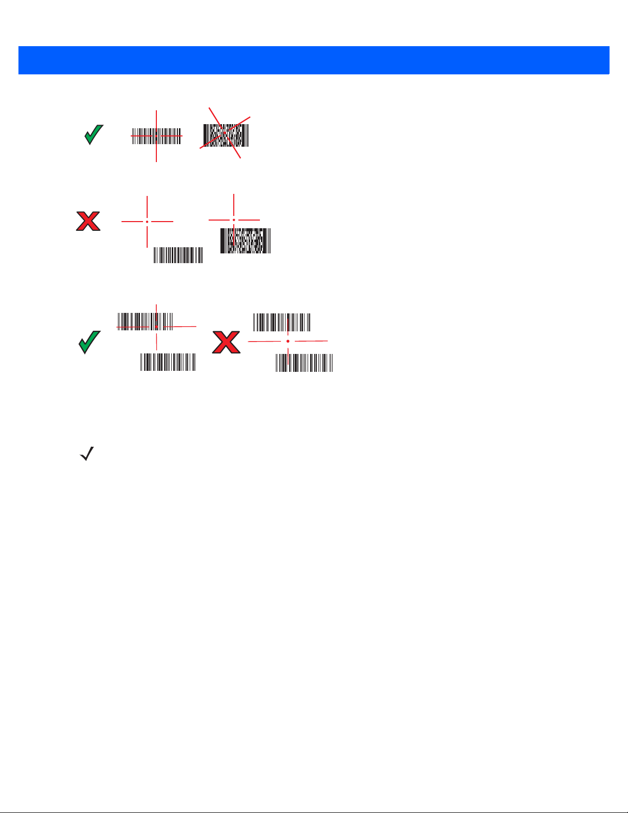
Data Capture 4 - 7
Figure 4-6
Figure 4-7
3. Release the scan button.
Imager Aiming Pattern
Pick List Mode with Multiple Bar Codes
NOTE Imager decoding usually occurs instantaneously. The MC9500-K repeats the steps required to take a digital
picture (image) of a poor or difficult bar code as long as the scan button remains pressed.
Page 84

4 - 8 MC9500-K Mobile Computer User Guide
In.
cm
0
20 mil Code 39
24.2
510152025
0 12.7 25.4 38.1 50.8 63.5
13 mil (100% UPC)
14.2
1.1
15.0
15 mil PDF417
0
cm
0
4.5
11.4
9
22.9
22.9
*
*
9
11.4
in.
4.5
11.9
15 mil Data Matrix
2.3
9.6
10 mil PDF417
*
10.1
7.5 mil Code 39
*
6.67 mil PDF417
2.9
6.6
5 mil Code 39
1.6
7.0
Note: Typical performance at 73°F (23°C) on high
quality symbols in normal room light.
Depth of Field
* Minimum distance determined by symbol length and scan angle.
W
i
d
t
h
o
f
F
i
e
l
d
Imager Decode Ranges
The decode ranges provide the decode distances for bar codes of specified densities. Figure 4-8 shows the imager
decode ranges and Table 4-2 on page 4-9 lists the scan ranges for the selected bar code densities. The minimum
element width (or “symbol density”) is the width in mils of the narrowest element (bar or space) in the symbol. The
maximum usable length of a symbol at any given range is shown below.
Figure 4-8
MC9500-K Imager Decode Ranges
Page 85

Data Capture 4 - 9
Table 4-2
Symbol Density/
Bar Code Type
5.0 mil
Code 39
6.67 mil
PDF417
7.5 mil
Code 39
10 mil
PDF417
13 mil
UPC-A
15 mil
PDF417
15 mil
Data Matrix
MC9500-K Imager Decode Distances
Bar Code Content/
Contrast
ABCDEFGH
80% MRD
4 Col, 20 Rows
80% MRD
ABCDEF
80% MRD
3 Col, 17 Rows
80% MRD
012345678905
80% MRD
80% MRD Note 1 14.2 in
18 x 18 Modules
80% MRD
Note 2
Typical Working Ranges
Near Far
1.6 in
4.06 cm
2.9 in
7.37 cm
Note 1 10.1 in
Note 1 9.6 in
1.1 in
2.79 cm
2.3 in
5.84 cm
7.0 in
17.78 cm
6.6 in
16.76 cm
25.65 cm
24.38 cm
15.0 in
38.10 cm
36.07 cm
11.9 in
30.23 cm
20 mil
Code 39
Notes:
1. Near distances are field-of-view (FOV) limited.
2. Contrast is measured as Mean Reflective Difference (MRD) at 670 nm.
3. Working range specifications at temperature = 23°C, pitch=18°, roll=0°, skew=0°, photographic quality, ambient
light ~30 ft.-c, humidity 45-70% RH.
Color Digital Camera
MC9500-K with an integrated color digital camera have the following features:
•
Photo capture
•
Video capture
•
Omnidirectional reading of a variety of bar code symbologies, including the most popular linear, postal,
PDF417, and 2D matrix code types.
•
Advanced intuitive aiming for easy point-and-shoot operation.
Digital Camera Scanning
123
80% MRD
Note 1 24.2 in
61.47 cm
The camera uses digital camera technology to take a digital picture of a bar code, stores the resulting image in its
memory, and executes state-of-the-art software decoding algorithms to extract the data from the image.
1. Ensure that a scan-enabled application is loaded on the MC9500-K.
Page 86

4 - 10 MC9500-K Mobile Computer User Guide
2. Aim the camera lens on the back of the MC9500-K at a bar code.
3. Press and hold the scan button. A preview window appears on the display window with a red aiming reticle in
the center. The Decode LED lights red to indicate that scanning is in process.
Figure 4-9
4. Move the MC9500-K until the red aiming reticle is over the bar code to scan.
5. The Decode LED lights green and a beep sounds, by default, to indicate the bar code was decoded
Sample Scan Application with Preview Window
successfully.
NOTE The camera decode feature is set by default to automatically decode the bar code when read. This feature
can be programmed to display a green aiming reticle upon good decode indicating that the bar code has
been successfully decoded and to that the scan button may be released.
Taking Photos
NOTE Ensure that the scanning/imaging application is disabled prior to enabling the camera.
To take a photo:
1. Ta p Start > Programs > Pictures & Videos icon.
2. Ta p Camera on the command bar.
3. Check the image on the view finder, adjust if necessary.
4. Press the Enter key to take the picture. Hold the MC9500-K still until the shutter sound is heard.
Recording Video
NOTE Ensure that the scanning/imaging application is disabled prior to enabling the camera.
To record a video clip:
1. Ta p Start > Programs > Pictures & Videos icon.
2. Ta p Camera on the command bar.
3. Ta p Menu > Video to set shooting mode to video.
The available recording time displays on the screen.
Page 87

NOTE By default, the time limit for recording videos is set to 30 seconds.
4. Press the Enter key to begin recording.
Recording stops when you press the Enter button again.
Viewing Photos and Videos
To view photos and video clips:
1. Ta p Start > Programs > Pictures & Videos icon.
2. Tap the picture or video clip to view.
Data Capture 4 - 11
Page 88

4 - 12 MC9500-K Mobile Computer User Guide
Page 89

Chapter 5 Using the Phone
Introduction
NOTE The MC959B supports only data communication. Phone features are disabled.
Use the MC9596 and MC9598 to make phone calls, set up speed dials, keep track of calls, and send text
messages. Your wireless service provider may also provide other services such as voice mail, call forwarding, and
caller ID.
Also use the integrated phone to connect to an ISP or work network in order to browse the Web and read e-mail.
Connect to the Internet or work network over High-Speed Downlink Packet Access (HSDPA) (MC9596 or MC959B)
or Evolution Data-Optimized (EvDO) (MC9598 or MC959B) using Cellular Line, or using the modem specified by
the mobile operator. For more information, or to customize the MC9500-K phone by changing phone settings, see
the MC9500-K Mobile Computer Integrator Guide.
Accessing the Phone Keypad
NOTE Keypads vary depending on services and the state of the phone.
On the MC959B, the phone dialer (keypad) is disabled.
Access the keypad regardless of the program in use. Applications on the MC9500-K can be in use during a call.
Page 90

5 - 2 MC9500-K Mobile Computer User Guide
Antenna Signal
MC9598
MC9596
Figure 5-1
To access the phone keypad tap Start > Phone, press the F1 key or press the green key.
To receive calls when the MC9500-K is suspended, leave the phone radio turned on and ensure the MC9500-K is
set to wake with any key.
Phone Keypads
Turning the Phone On and Off
Windows Mobile 6.1 devices include Wireless Manager, which provides a simple method of enabling and
disabling the phone.
To open Wireless Manager, tap the Connectivity icon.
Figure 5-2
Select Wireless Manager. The Wireless Manager window appears.
To toggle on or off the phone, tap Phone bar on the MC9596 or MC9598 or tap Broadband on the MC959B.
To configure settings for a connection, tap Menu > Phone Settings.
Opening Wireless Manager
NOTE To receive calls when your device is suspended, leave the phone turned on.
Page 91

Audio Modes
Headset ModeHandset Mode Speaker Mode
The MC9500-K offers three audio modes for use during phone calls:
•
Handset Mode: Switches audio to the speaker at the top front of the MC9500-K, so you can use the
MC9
•
Speaker Mode: Use the MC9500-K as if on speaker phone. Tap the Speaker On button to activate this
mo
de. Tap the Speaker Off button to switch back to handset mode.
•
Headset Mode: Connect a Bluetooth headset or a wired headset to automatically switch audio to the
headset.
The MC9500-K defaults to handset mode. When a wired headset is plugged into the MC9500-K headset connector
or a Bluetooth headset is configured for use with the MC9500-K, the earpiece and speakerphone are muted and
audio is heard through the headset.
NOTE While using a Bluetooth headset during a call, the mobile computer will not go into suspend mode.
Using the Phone 5 - 3
500-K as a handset. This is the default mode.
Figure 5-3
Audio Modes
Using a Wired Headset
NOTE Remove the headset jack plug before connecting the Headset Adapter to the MC9500-K.
You can use a stereo headset for audio communication when using an audio-enabled application. To use a
headset, plug the headset jack of the Headset Adapter Cable into the headset connector on the side of the
MC9500-K. Plug the Headset connector into the connector on the Headset Adapter Cable. Set the MC9500-K’s
volume appropriately before putting the headset on. Plugging a headset into the jack mutes the speaker.
Page 92
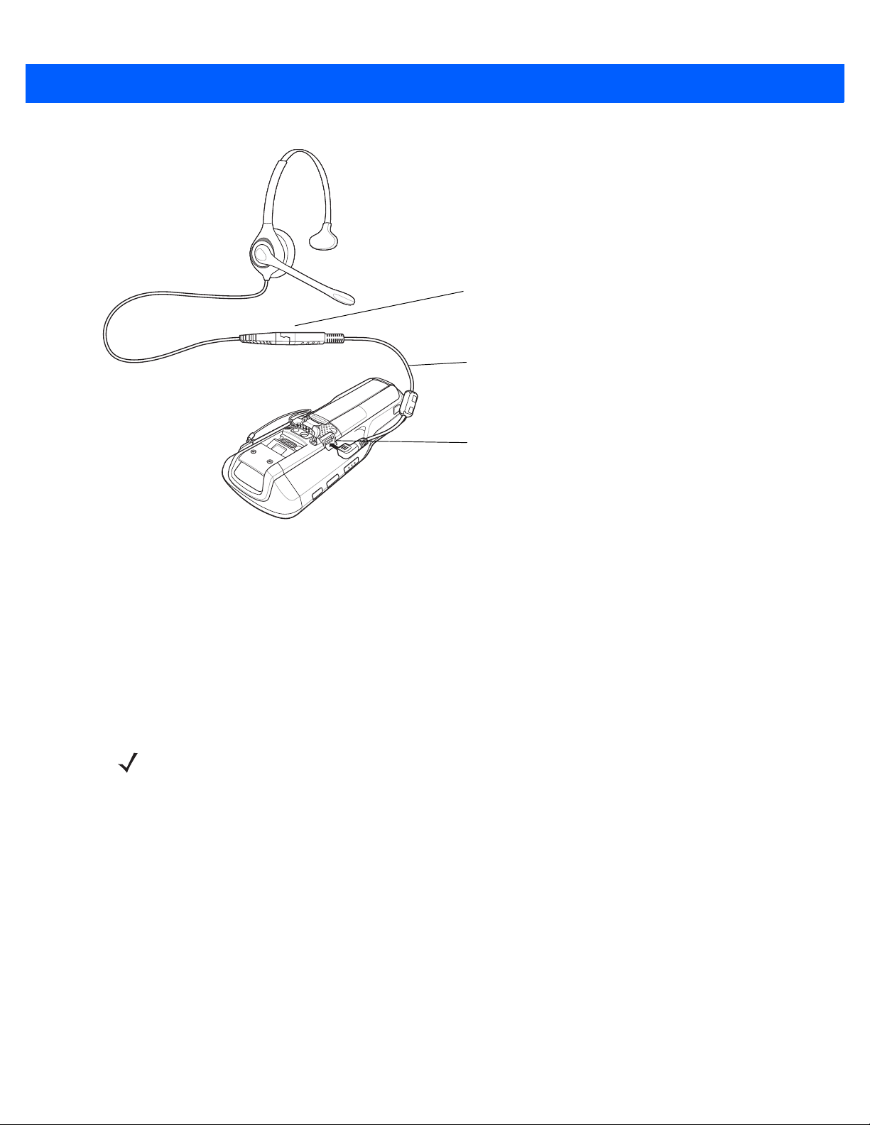
5 - 4 MC9500-K Mobile Computer User Guide
Headset Adapter
Cable
Breakaway
Connectors
Headset
Connector
Figure 5-4
Using a Headset
Using a Bluetooth Headset
You can use a Bluetooth headset for audio communication when using an audio-enabled application. See Chapter
7, Using Bluetooth for information on connecting a Bluetooth headset to the MC9500-K. Set the MC9500-K’s
volume appropriately before putting the headset on. When a Bluetooth headset is connected the speakerphone is
muted.
It is recommended for phone conversations to use the Bluetooth Hands-free profile instead of the Headset profile.
See Chapter 7, Using Bluetooth for more information.
NOTE When using a Bluetooth headset, during a call, the MC9500-K power button is disabled and the MC9500-K
will not go into suspend mode. Once the call is completed, the power button functionality is enabled.
The following dialog box displays when a Bluetooth headset connection is established and the power button is
pressed.
Page 93

Using the Phone 5 - 5
Phone Volume Slider
Figure 5-5
WWAN Bluetooth Audio Notification Dialog Box
Adjusting Audio Volume
Use the Volume Control Slider or the keypad keys to adjust the volume of the ringer when not in a call and the
audio volume when in a call.
Figure 5-6
To adjust the volume tap the Speaker icon in the Title bar. Move the slider up or down to adjust the volume.
Phone Volume Slider
NOTE Adjust the conversation phone volume during a call. Adjusting the volume while not in a call affects the ring
and notification sound levels.
Hearing Aid Compatibility Setting
NOTE Supported on MC9596-K and MC9598-K configurations only.
To set the Hearing Aid Compatibility (HAC) setting:
Ta p Start > Settings> System > HAC Settings icon. The HAC Settings window appears.
Page 94

5 - 6 MC9500-K Mobile Computer User Guide
Figure 5-7
To enable the HAC feature, tap the Enable HAC radio button.
To disable the HAC feature, tap the Disable HAC radio button.
Making a Call
NOTE You can make emergency calls even when the MC9500-K is locked or when a SIM card is not installed. See
With the MC9500-K, you can make a call from the phone, contacts, speed dial and call history.
Using the Phone
To make a call using the phone keypad:
1. Ta p Start > Phone or press the green key.
2. From the Phone keypad, tap the number to call.
3. Ta p Talk.
4. Ta p End to stop dialing or end the call.
HAC Settings Window
Making an Emergency Call on page 5-10 for more information.
NOTE Alternatively, use the green and red keys on the MC9500-K function key to dial (green) and end (red) calls.
If you tap a wrong number, tap Delete key to erase each subsequent digit of a number. To erase the entire
number, tap and hold the Delete key.
Using Contacts
Use Contacts to make a call without looking up or entering the phone number.
To make a call from Contacts:
1. Ta p Start > Contacts.
2. From the contact list, tap and hold the contact name.
Page 95

Using the Phone 5 - 7
Notes is a good place for
maps and directions
Scroll to see more fields
Tap to return to the contact list
(the contact is saved automatically)
3. Ta p Call Work, Call Home or Call Mobile.
NOTE To make a call from an open contact, tap the number to call. See On-Device Help for more information about
Contacts.
Creating an Outlook Contact
NOTE When entering a contact phone number that contains a star (*) character followed by a plus (+) character, save
the contact as an Outlook Contact. Do not save the contact to a SIM card.
To create an Outlook contact:
1. Ta p Start > Contacts.
2. Ta p New.
3. If the Phone is on the Select Contact Type window displays. Select Outlook Contact.
Figure 5-8
4. Using the input panel, tap in each field and enter contact information as needed. Scroll down to see all fields.
5. Tap the arrow next to the Name: or Home addr: field to open a window for adding more details.
6. To assign the contact to a category, tap Categories.
7. To select one or more categories for the contact, select their check boxes. This allows displaying contacts by
Creating a Contact
category in the contact list.
8. Ta p New to add a category.
9. Enter the name for the category in the text box, and tap ok.
10. Ta p ok.
11. To add notes, tap the Notes tab and enter text, draw, or create a recording.
12. When finished, tap ok to return to the contact list.
Editing an Outlook Contact
To make changes to a contact:
1. Ta p Start > Contacts.
Page 96

5 - 8 MC9500-K Mobile Computer User Guide
2. Tap the contact in the contact list to open it.
3. Ta p Menu > Edit and make the changes.
4. Ta p ok.
Deleting a Contact
To delete a contact:
1. Ta p Start > Contacts.
2. Tap and hold the contact in the contact list and select Delete Contact from the pop-up menu, or select the
contact and tap Menu > Delete Contact.
Creating a SIM Contact
To create a SIM contact:
NOTE When entering a contact phone number that contains a star (*) character followed by a plus (+) character, save
the contact as an Outlook Contact. Do not save the contact to a SIM card.
1. Ta p Start > Contacts.
2. Ta p New.
3. Select SIM Contact.
Figure 5-9
4. Using the input panel, tap in each field and enter contact information.
5. When finished, tap ok to return to the contact list.
Creating a SIM Contact
Using Call History
To make a call using Call History:
1. Ta p Start > Phone or press the green key.
2. From the Phone keypad, tap Call History.
Page 97

Using the Phone 5 - 9
Phone icon
Speed Dial
Location Number
Figure 5-10
3. Tap the phone icon next to the number to begin dialing and return to the phone keypad.
4. Ta p End or press the red key to stop dialing or end the call.
Call History
Making a Speed Dial Call
Use Speed Dial to call someone saved in the speed dial directory.
To make a speed dial call:
1. Ta p Start > Phone or press the green key.
2. From the Phone keypad, tap and hold the speed dial location number assigned to a contact. (To dial a one-digit
spe
ed dial location number, tap and hold the speed dial number. To dial a two-digit speed dial location number
t
ap the first digit and then tap and hold the second digit.)
or
From the Phone keypad, tap Speed Dial and tap the speed dial location number of the desired contact in the
list.
,
Figure 5-11
3. To stop dialing or end the call, tap End or press the red key.
Speed Dial Contact List
Page 98

5 - 10 MC9500-K Mobile Computer User Guide
Making an Emergency Call
NOTE Supported on MC9596-K and MC9598-K configurations only.
Your service provider programs one or more emergency phone numbers, such as 911 or 999, that you can call
under any circumstances, even when your phone is locked or the SIM card is not inserted. Your service provider
can program additional emergency numbers into your SIM card. However, your SIM card must be inserted in your
phone in order to use the numbers stored on it. See your service provider for additional information.
When the alpha primary keypad is locked, press the Orange key twice to set the keypad to numeric mode and then
enter the emergency number.
NOTE Emergency numbers vary by country. Your phone’s pre-programmed emergency number(s) may not work in
all locations, and sometimes an emergency call cannot be placed due to network, environmental, or
interference issues.
Answering a Call
A dialog box appears on the MC9500-K when it receives an incoming call. If the phone is set to ring, a ring tone
sounds. Answer or ignore the incoming call.
To answer an incoming call tap Answer on the Phone > Incoming... dialog or press the green key.
Figure 5-12
To ignore the incoming call tap Ignore. This may send the caller to voice mail, depending on the service provider.
Otherwise, this presents Busy to the calling party.
To end the call tap End or press the red key.
Incoming Call
Incoming Call Features
•
If you receive a call while in a call, tap Wait to place the call in call waiting.
•
You can use other programs on the MC9500-K during a call. To switch back to Phone, tap Tal k or tap Start >
Phone. T
ap End to end the call.
Page 99

•
If a caller isn't in your contact list, create a contact during the call or from Call History by tapping Menu >
Save to Contacts.
•
To terminate a call when a second call comes in and answer the waiting call, tap End on the Phone keypad to
disconnect the active call, then tap Answer or press the Send key to answer the waiting call.
•
To hold the current call and answer a waiting call, tap Answer or press the Send key to place the current call
on hold and answer the incoming call.
•
To put a call on hold to call another number or answer an incoming call, tap Hold. To move from one call to
another, tap Swap.
Smart Dialing
Smart Dialing makes it easy to dial a phone number. When you start entering numbers or characters, Smart Dialing
automatically searches and sorts the contact entries on the SIM card, in Contacts, and the phone numbers in Call
History (including incoming, outgoing, and missed calls). You can then select the desired number or contact from
the filtered list to dial.
Open the Phone screen, then tap the keys on the Phone keypad that correspond to the phone number or contact to
call. The contact panel lists contacts that match the sequence that you entered.
Using the Phone 5 - 11
Smart Dialing starts looking for numbers or contacts that match the sequence entered.
To find a phone number:
•
Enter the first one or two digits to find a phone number in Call History.
•
Enter the first three digits or more to find a phone number from the saved Contacts and SIM card.
To find a contact name:
• Enter the first letter of a contact’s first name or last name. Smart Dialing searches for the letter starting
from the first character of a contact name as well as from the character that appears after a space, dash,
or underscore in a contact name. For example, if you tap number “2” which is associated with [a, b, c] on
the Phone keypad, contact names such as the following will be considered matches: “Smith, Bernard”,
“Adams, John”, “Carlson, Eileen”, “Dillon, Albert”, “Childs, Larry”, “Cooper, Robert” and “Parks, Celine”.
• If the matching list is long narrow down the search further by entering another letter. Using the same
example above, tap “3” which is associated with (d, e, f), the matching list is narrowed down to the
following names: “Smith, Bernard”, “Adams, John”, and “Parks, Celine”.
Figure 5-13
Finding a Contact
Page 100
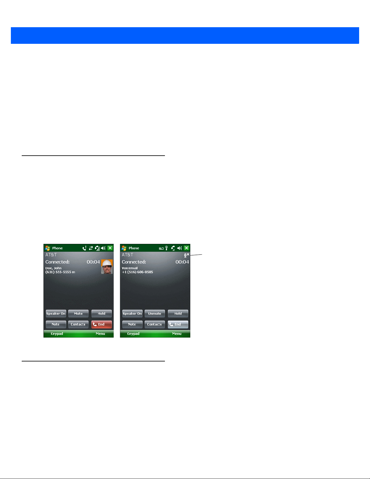
5 - 12 MC9500-K Mobile Computer User Guide
Mute Icon
To make a call or send a text message using Smart Dialing:
1. Begin entering the first few numbers or characters.
2. In the Smart Dialing panel, use the up and down arrows on the keypad to navigate to the desired contact or
phone number.
3. When the correct contact is selected, press TAL K to make a voice call.
4. To send a text message to the selected contact, tap Menu > Send Text Message.
5. To call a different phone number associated with the selected contact, tap the contact name and select the
phone number to call.
Muting a Call
During a call, you can mute the microphone so you can hear the person on the line but he or she cannot hear
conversation from the microphone. This is useful when there is conversation or background noise on your end.
To mute or unmute a call:
1. Ta p Start > Phone or press the green key.
2. Make a call.
3. Ta p Mute on the display to mute the audio. The Mute icon appears.
Figure 5-14
Taking Notes
To create a note during a call, tap Note on the display, then enter the note. For more information about creating
notes see the Windows On-Device Help.
To access a note created during a call:
Mute Button and Icon
1. Ta p Start > Phone or press the green key.
2. From the Phone keypad, tap Call History.
3. Tap and hold the number or the Note icon for the phone call entry containing the note.
 Loading...