

LS3008
Quick Reference Guide

Quick Reference Guide 2
© 2015 Symbol Technologies, Inc.
Zebra reserves the right to make changes to any product to improve reliability, function,
or design.
Zebra does not assume any product liability arising out of, or in connection with, the
application or use of any product, circuit, or application described herein.
No license is granted, either expressly or by implication, estoppel, or otherwise under
any patent right or patent, covering or relating to any combination, system, apparatus,
machine, material, method, or process in which Zebra products might be used. An
implied license exists only for equipment, circuits, and subsystems contained in Zebra
products.
Zebra and the Zebra head graphic are registered trademarks of ZIH Corp. The Symbol
logo is a registered trademark of Symbol Technologies, Inc., a Zebra Technologies
company.
Zebra Technologies Corporation
Lincolnshire, IL U.S.A.
http://www.zebra.com
Warranty
For the complete Zebra hardware product warranty statement, go to:
http://www.zebra.com/warranty.
For Australia Only
For Australia Only. This warranty is given by Zebra Technologies Asia Pacific Pte. Ltd.,
71 Robinson Road, #05-02/03, Singapore 068895, Singapore. Our goods come with
guarantees that cannot be excluded under the Australia Consumer Law. You are
entitled to a replacement or refund for a major failure and compensation for any other
reasonably foreseeable loss or damage. You are also entitled to have the goods
repaired or replaced if the goods fail to be of acceptable quality and the failure does not
amount to a major failure.
Zebra Technologies Corporation Australia's limited warranty above is in addition to any
rights and remedies you may have under the Australian Consumer Law. If you have
any queries, please call Zebra Technologies Corporation at +65 6858 0722. You may
also visit our website: http://www.zebra.com for the most updated warranty terms.

Quick Reference Guide 3
Interface cable
modular
connector
To h o s t
Beeper
LED
Trigger
Scan
Window
Cable interface
port
Connector
clip
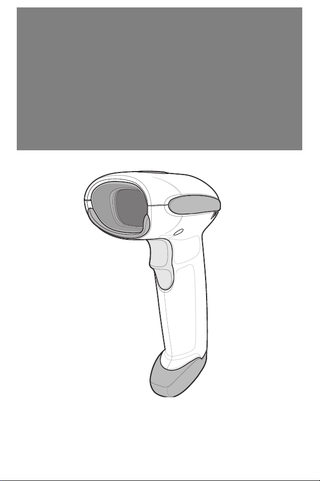
Introduction
The LS3008 scanner combines excellent scanning performance
and advanced ergonomics to provide the best value in a
lightweight laser scanner. Whether used as a hand-held scanner
or in hands-free mode in a stand, the scanner ensures comfort
and ease of use for extended periods of time. Before
programming the scanner, scan the appropriate bar code(s),
beginning on
page 8, to communicate with the host.
Parts
Inserting and Removing the Interface Cable
To connect the interface cable, insert the interface cable’s modular
connector into the cable interface port.
To remove the interface cable, unplug the installed cable’s modular
connector by depressing the connector clip with the tip of a screwdriver.
Quick Reference Guide 4
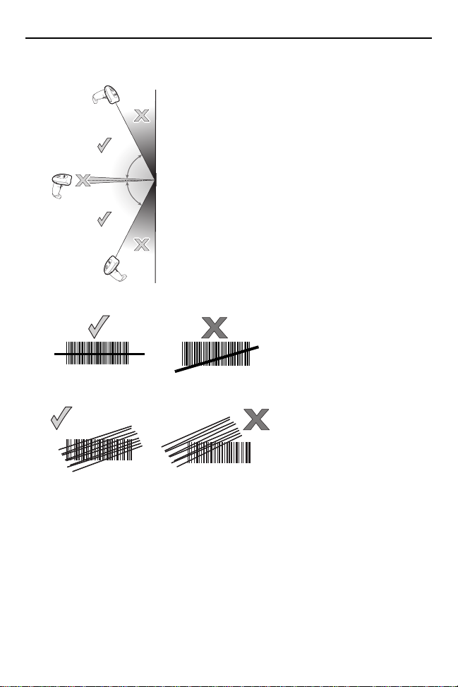
65
o
65
o
012345
012345
012345
Aiming
Scanning
012345
Quick Reference Guide 5
Beeper Definitions
The scanner issues different beep sequences and patterns to indicate
status. The table below defines beep sequences that occur during both
normal scanning and while programming the scanner.
Beeper Sequence Indication
Standard Use
Low/medium/high beep Power up.
Short high beep A bar code symbol was decoded (if decode beeper is
enabled).
4 long low beeps A transmission error was detected in a scanned
5 low beeps Conversion or format error.
Low/high/low beep ADF transmit error.
High/high/high/low beep RS-232 receive error.
Parameter Menu Scanning
Short high beep Correct entry scanned or correct menu sequence
Low/high beep Input error, incorrect bar code or “Cancel” scanned,
High/low beep Keyboard parameter selected. Enter value using bar
High/low/high/low beep Successful program exit with change in the parameter
Low/high/low/high beep
Code 39 Buffering
High/low beep New Code 39 data was entered into the buffer.
3 Beeps - long high beep Code 39 buffer is full.
symbol. The data is ignored. This occurs if a unit is not
properly configured. Check option setting.
performed.
wrong entry, incorrect bar code programming
sequence; remain in program mode.
code keypad.
setting.
Out of host parameter storage space. Scan
Defaults on page 8
.
Set

Quick Reference Guide 6
Beeper Sequence Indication
Low/high/low beep The Code 39 buffer was erased or there was an
Low/high beep A successful transmission of buffered data.
Host Specific
USB only
4 short high beeps Scanner has not completed initialization. Wait several
Scanner gives a
power-up beep after
scanning a USB Device
Type.
This power-up beep
occurs more than once.
RS-232 only
1 short high beep A <BEL> character is received and Beep on <BEL> is
attempt to clear or transmit an empty buffer.
seconds and scan again.
Communication with the bus must be established
before the scanner can operate at the highest power
level.
The USB bus may put the scanner in a state where
power to the scanner is cycled on and off more than
once. This is normal and usually happens when the
host PC cold boots.
enabled.
LED Definitions
In addition to beeper sequences, the scanner communicates with the
user using a two-color LED display. The table below defines LED colors
that display during scanning.
LED Indication
Off No power is applied to the scanner, or the scanner is
on and ready to scan.
Green A bar code was successfully decoded.
Red A data transmission error or scanner malfunction
occurred.
 Loading...