


FS10/xS20
Smart Camera
Product Reference Guide
MN-004336-01EN Rev A

ZEBRA and the stylized Zebra head are trademarks of Zebra Technologies Corporation, registered in
many jurisdictions worldwide. All other trademarks are the property of their respective owners.
©2021 Zebra Technologies Corporation and/or its affiliates. All rights reserved.
Information in this document is subject to change without notice. The software described in this document
is furnished under a license agreement or nondisclosure agreement. The software may be used or copied
only in accordance with the terms of those agreements.
For further information regarding legal and proprietary statements, please go to:
SOFTWARE:zebra.com/linkoslegal
COPYRIGHTS:zebra.com/copyright
WARRANTY:zebra.com/warranty
END USER LICENSE AGREEMENT: zebra.com/eula
Terms of Use
Proprietary Statement
This manual contains proprietary information of Zebra Technologies Corporation and its subsidiaries
(“Zebra Technologies”). It is intended solely for the information and use of parties operating and
maintaining the equipment described herein. Such proprietary information may not be used, reproduced,
or disclosed to any other parties for any other purpose without the express, written permission of Zebra
Technologies.
Product Improvements
Continuous improvement of products is a policy of Zebra Technologies. All specifications and designs are
subject to change without notice.
Liability Disclaimer
Zebra Technologies takes steps to ensure that its published Engineering specifications and manuals are
correct; however, errors do occur. Zebra Technologies reserves the right to correct any such errors and
disclaims liability resulting therefrom.
Limitation of Liability
In no event shall Zebra Technologies or anyone else involved in the creation, production, or delivery of the
accompanying product (including hardware and software) be liable for any damages whatsoever
(including, without limitation, consequential damages including loss of business profits, business
interruption, or loss of business information) arising out of the use of, the results of use of, or inability to
use such product, even if Zebra Technologies has been advised of the possibility of such damages. Some
jurisdictions do not allow the exclusion or limitation of incidental or consequential damages, so the above
limitation or exclusion may not apply to you.
i

Contents
Terms of Use .......................................................................................................................... i
Proprietary Statement .......................................................................................................... i
Product Improvements ......................................................................................................... i
Liability Disclaimer ............................................................................................................... i
Limitation of Liability ............................................................................................................. i
Service Information ............................................................................................................... v
Getting Started
Configurations ....................................................................................................................... 1
Accessories ........................................................................................................................... 1
Cables ................................................................................................................................. 1
Power Supplies (xS20 Only) ............................................................................................... 2
FS10 and xS20 Smart Camera Specifications ...................................................................... 3
FS10 Specifications ............................................................................................................ 3
xS20 Specifications ............................................................................................................... 5
Installation
Dimensional Drawings .......................................................................................................... 7
FS10 Dimensional Drawings ............................................................................................... 7
xS20 Dimensional Drawings ............................................................................................... 8
FS10 Connection ................................................................................................................ 9
xS20 Connections ............................................................................................................... 9
Torque Specification ......................................................................................................... 10
Power Sources .................................................................................................................... 11
12 Pin M12 Power Input (xS20 only) ................................................................................ 11
Power Over Ethernet (xS20 Only) .................................................................................... 11
USB Type C (xS10 Only) .................................................................................................. 11
Grounding for Electro-Magnetic Compliance and ESD Safe .............................................. 11
Cable Pin Outs .................................................................................................................... 12
Power and I/O Connector (xS20 Only) ............................................................................. 12
Ethernet Connector (xS20 Only) ....................................................................................... 13
Setting up an FS/VS Smart Camera ................................................................................... 14
Mounting Instructions ........................................................................................................ 14
Mounting the Device Using the L-Bracket Accessory (BRKT-LMNT-U000) ..................... 14
ii

FS10 Mounting Options .............................................................................................. 15
xS20 Mounting Options ............................................................................................... 16
Using the Smart Camera
USB Type C (FS10 Only) .................................................................................................... 18
User Interface ...................................................................................................................... 18
Data Capture ....................................................................................................................... 18
LED and Beeper Indicators ................................................................................................. 20
FS10/xS20 Decode Ranges ................................................................................................ 22
General Purpose Input and Outputs ................................................................................... 23
Optically Coupled GPIO .................................................................................................... 23
Thermal Management ......................................................................................................... 25
Zebra Aurora Software Overview
Human-Machine Interface (HMI) ....................................................................................... 26
Industrial Ethernet Information .......................................................................................... 26
Zebra Aurora Features ........................................................................................................ 26
Device Discovery ................................................................................................................ 27
Network Setup (xS20 only) ............................................................................................... 29
Configuring Device Settings ................................................................................................ 30
Communication Settings ................................................................................................... 31
General Settings ............................................................................................................... 32
GPIO Mapping (xS20 only) ............................................................................................... 33
Building and Deploying Fixed Scanning (FS) Jobs ............................................................. 34
Building and Deploying Vision System (VS) Jobs (xS20 only) ............................................ 35
Using the QuickDraw Tool ................................................................................................ 35
Accessing the Web Human-Machine Interface (HMI) ......................................................... 37
Live Monitoring with the Web HMI .................................................................................... 38
Accessing the Device Using the Web HMI ....................................................................... 39
Factory Reset ...................................................................................................................... 41
Software License Activation Methods ................................................................................. 43
Obtaining a License Key ................................................................................................... 43
Activating a License with Zebra Aurora ............................................................................ 44
Supported Symbologies ...................................................................................................... 44
Contents
Troubleshooting
Communicating with the Device .......................................................................................... 46
Pinging the Device via IP .................................................................................................. 46
Pinging the Device via Hostname ..................................................................................... 46
Device Discovery Troubleshooting Methods ....................................................................... 47
Factory Reset the Device .................................................................................................. 47
Power Cycling the Device ................................................................................................. 47
Security Settings ................................................................................................................. 48
Zebra Aurora Communication Port Usage .......................................................................... 49
iii

Maintenance
Contents
Maintenance ........................................................................................................................ 50
Known Harmful Ingredients ............................................................................................... 50
Approved Cleaning Agents ............................................................................................... 50
Tolerable Industrial Fluids and Chemicals ................................................................................. 51
Cleaning the Device .......................................................................................................... 51
iv

About This Guide
Introduction
The FS/VS Smart Camera Series Product Reference Guide provides general instructions for
integrating, setting up, and programming the device.
IMPORTANT: If you have a problem with your equipment, contact Zebra Global Customer Support for
your region. Contact information is available at: zebra.com/support.
Related Documents and Software
The documentation set provides information for specific user needs, and includes:
• Industrial Ethernet User Guide
For the latest version of this guide and all guides, go to: zebra.com/support
Service Information
If you have a problem with your equipment, contact Zebra Global Customer Support for your region.
Contact information is available at: zebra.com/support.
When contacting support, please have the following information available:
• Serial number of the unit.
• Model number or product name.
• Software type and version number.
Zebra responds to calls by email, telephone or fax within the time limits set forth in support
agreements.
If your problem cannot be solved by Zebra Customer Support, you may need to return your equipment
for servicing and will be given specific directions. Zebra is not responsible for any damages incurred
during shipment if the approved shipping container is not used. Shipping the units improperly can
possibly void the warranty.
If you purchased your Zebra business product from a Zebra business partner, contact that business
partner for support.
v

Getting Started
This section outlines the configurations, accessories, and specifications of the FS/VS Smart Camera
Series.
Configurations
Fixed Industrial Scanning (FS) devices come equipped with a USB or PoE scanner with auto focus, while
Vision System (VS) devices come equipped with a smart PoE Sensor with adjustable focus.
Table 1 FS10/xS20 Configurations
Device Description
FS10 Fixed Industrial USB Scanner, Auto Focus, Standard Range,
1.0MP, Fast 2D Barcode Decoder, Red and White illumination
FS20 Fixed Industrial PoE Scanner, Auto Focus, Standard Range,
1.0MP, Ethernet with PoE, Serial and Industrial Protocols, Red or
White Illumination
VS20 Smart PoE Sensor, Adjustable Focus, Standard Range, 1.0MP,
Sensor Toolset with Fast 2D Decode, Ethernet with PoE, Serial and
Industrial Protocols, Red or White Illumination
Accessories
Supported cables and power supplies for FS10 and xS20 devices are listed below.
Cables
FS10 devices utilize USB-C to C or USB-C to A cables, while xS20 devices utilize X-coded Ethernet and
power, serial, and GPIO cables.
Table 2 Cables
Device Part Number Description
FS10 CBL-USB03000-USC00 Cable, USB 2M, locking USB-C to USB C
CBL-USB04000-USC00 Cable, USB 4M, locking USB-C to USB C
CBL-USB02000-USA00 Cable, USB 2M, locking USB-C to USB A
CBL-USB04000-USA00 Cable, USB 4M, locking USB-C to USB A
1

Table 2 Cables
Device Part Number Description
xS20
CBL-ENT00500-M1200
CBL-ENT01500-M1200
CBL-PWR00500-M1200 Cable, power 5M, 12 Pin M12 to flying leads, standard flex
CBL-PWR01500-M1200 Cable, power 15M, 12 Pin M12 to flying leads, standard flex
Power Supplies (xS20 Only)
The xS20 device supports the use of 24 V power supplies.
Table 3 Power Supply
Part Number Description
PWR-24V03A-0000 Power supply, 24VDC 3AMP, DIN rail mount
PWR-24V05A-0000 Power supply, 24VDC 5AMP, DIN rail mount
PWR-POE30W-0000 Power over Ethernet injector, 30W POE+, AC input
Getting Started
Cable, Ethernet 5M, X-Coded M12 to RJ45, standard flex
Cable, Ethernet 15M, X-Coded M12 to RJ45, standard flex
2

Getting Started
FS10 and xS20 Smart Camera Specifications
The following table outlines the physical characteristics, performance characteristics, user environment,
and regulatory approvals of FS10 and xS20 devices.
FS10 Specifications
Table 4 FS10 Specifications
Item Description
Physical Characteristics
Dimensions
Weight 110 g/3.9 oz
Power USB Type-C, 1A max
Interface Ports (1) USB Type C supports USB 2.0 high speed only
Communication Protocols USB RNDIS, HID, CDC
Performance Characteristics
Image Sensor Monochrome: 1.0 MP (1280x800 pixels) CMOS
Acquisition Rate 60 frames/second
Aimer 617nm Red LED aim dot
Illumination (1) 2700K (Color Temperature) White LED
Imager Field of View 35°(H) x 26°(V)
User Environment
Operating Temperature 0°C - 45°C (32°F to 113°F)
1.0 in. H x 2.0 in. W x 1.92" D
25.4 mm H x 50.8 mm W x 48.9mm D
Sensor with Global Shutter and 3.0 um pixel size
(1) 660nm Red LED
(duty cycle-dependent)
Storage Temperature -40° to 70°C (-40°F to 158°F)
Humidity 5 % to 90 % RH (Non Condensing)
Vibration Resistance EN 60068-2-6, 14 mm @ 2 to 10 Hz, 1.5 mm @ 13 to 55
Hz; 2 g @ 70 to 500 Hz; 2 hours on each axis
Shock Resistance EN 60068-2-27, 30g; 11 ms; 3 shocks on each axis
Sealing IP65 and IP67
Light Immunity Product operates in: Incandescent 450 ft candles, Sunlight
<6000 ft candles, Florescent 450 ft candles, Mercury
Vapor 450 ft candles, Sodium Vapor 450 ft candles, LED
450 ft candles
Electrostatic Discharge ±15kV Air, ±8kV Contact
3

Getting Started
Table 4 FS10 Specifications
Item Description
Trigger Durability Withstand 1,000 cycles of operation with no degradation in
functionality
Regulatory Approvals
Environmental EN 50581:2012
EN IEC 63000:2018
Electrical Safety IEC 62368-1 (Ed.2)
EN 62368-1:2014/A11:2017
LED Safety IEC 62471: 2006 (Ed.1)
EN 62471: 2008
EMI/EMS EN 55032:2015/A11: 2020
EN 55035:2017/A11: 2020
EN 61000-3-2: 2014
EN 61000-3-3: 2013
EN 61000-6-2: 2005 & 2019
FCC 47 CFR Part 15, Subpart B
Canada ICES-003, Issue 7
EU Declaration of Conformity 2014/30/EU; 2014/35/EU; 2011/65/EU
Refer to the Declaration of Conformity (DoC) for details of
compliance to the current standards. The DoC is available
at: zebra.com/doc
4

xS20 Specifications
Table 5 xS20 Specifications
Physical Characteristics
Getting Started
Item Description
Dimensions
Weight 200 g/7.1 oz
Power 10 to 30 VDC external power supply, 7W max at 24V
Configurable IO (4) Four opto-isolated GPIO: 2 dedicated inputs(IN0/IN1),
Interface Ports (1) M12 X-Coded 1000/100/10 Mbps Ethernet
Communication Protocols Ethernet/IP, PROFINET, CC-Link, Modbus TCP, TCP/IP
Performance Characteristics
Image Sensor Monochrome: 1.0 MP (1280x800 pixels) CMOS
Acquisition Rate Up to 60 frames/second
Aimer 617nm Red LED aim dot
Illumination
1.1 in. H x 2.15 in. W x 3.71 in D
28.3 mm H x 54.6 mm W x 94.3 mm D
Class 2 PoE, 7W
2 dedicated outputs (OUT0/OUT1)
(1) M12 12-pin Power/GPIO/Serial
Sensor with Global Shutter and 3.0 um pixel size
(2) 2700K (Color Temperature) White LEDs
or (depending on model)
(2) 660nm Red LEDs
Imager Field of View
User Environment
Operating Temperature 0°C - 45°C (32°F to 113°F)
Storage Temperature -40° to 70°C (-40°F to 158°F)
Humidity 5 % to 90 % RH (Non Condensing)
Vibration Resistance EN 60068-2-6, 14 mm @ 2 to 10 Hz, 1.5 mm @ 13 to 55
Shock Resistance EN 60068-2-27, 30g; 11 ms; 3 shocks on each axis
Sealing IP65 and IP67
Light Immunity Product operates in: Incandescent 450 ft candles, Sunlight
Electrostatic Discharge ±15kV Air, ±8kV Contact
35°(H) x 26°(V)
(duty cycle-dependent)
Hz; 2 g @ 70 to 500 Hz; 2 hours on each axis
<6000 ft candles, Florescent 450 ft candles, Mercury
Vapor 450 ft candles, Sodium Vapor 450 ft candles, LED
450 ft candles
5

Getting Started
Table 5 xS20 Specifications
Item Description
Trigger Durability Withstand 1,000 cycles of operation with no degradation in
functionality
Regulatory Approvals
Environmental EN 50581:2012
EN IEC 63000:2018
Electrical Safety IEC 62368-1 (Ed.2)
EN 62368-1:2014/A11:2017
LED Safety IEC 62471: 2006 (Ed.1)
EN 62471: 2008
EMI/EMS EN 55032:2015/A11: 2020
EN 55035:2017/A11: 2020
EN 61000-3-2: 2014
EN 61000-3-3: 2013
EN 61000-6-2: 2005 & 2019
FCC 47 CFR Part 15, Subpart B
Canada ICES-003, Issue 7
EU Declaration of Conformity 2014/30/EU; 2014/35/EU; 2011/65/EU
Refer to the Declaration of Conformity (DoC) for details of
compliance to the current standards. The DoC is available
at: zebra.com/doc
6

Installation
This section describes the mounting procedure for the FS10/xS20 series.
Dimensional Drawings
The following illustrations display the dimensions and mounting orientation for FS10 and xS20 devices.
Use the guidance provided to mount the device to an L-bracket as shown in Mounting Instructions.
FS10 Dimensional Drawings
Figure 1 FS10 Dimensional Drawings
Optical Axis
15.00
12.80±1.00
For use with a Zebra
USB-C locking cable
2 X 8.83
5.3
19.25±1.00
12.70±1.00
19.25±1.00
50.80±0.60
38.50
Optical Axis
25.40
38.50
4X M3 X 0.50
X 3.75 MAX DEPTH
48.88±0.60
2X 37.21±0.50
2X 3.90
2X 3.90
2X 12.8
25.4
7
2X M3 X 0.50 THD
X 3.75 MAX DEPTH
Optical Axis
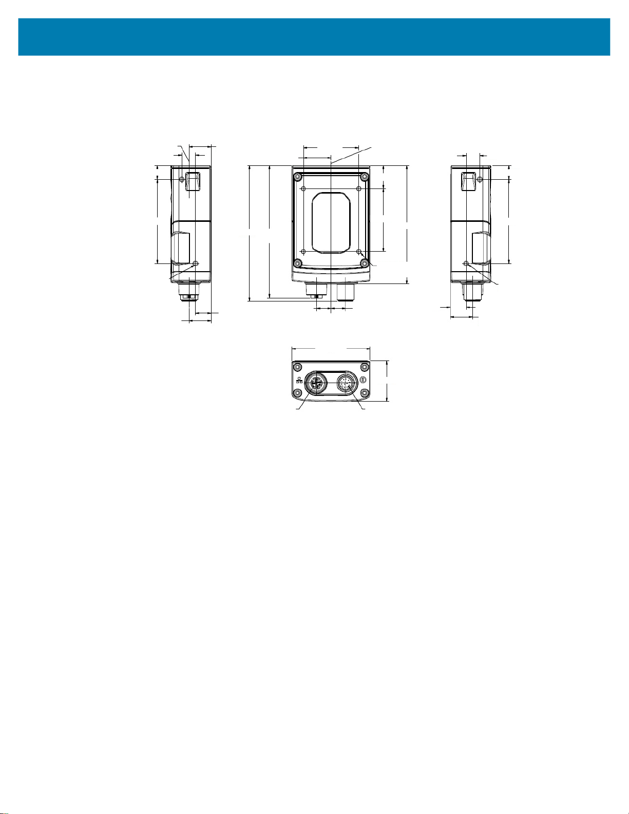
xS20 Dimensional Drawings
Figure 2 xS20 Side Dimensional Drawings
Installation
Optical Axis
9.48
9.66±.50
58.45
2X M3 X 0.50 THD
X 4.5 MAX DEPTH
8 PIN M12
CONNECTOR
15.50
15.51±1.00
Optical Axis
94.23±1.00
11.00
2X19.25±1.00
91.83±1.00
8 PIN M12
CONNECTOR
8 PIN M12
CONNECTOR
10.13
2X 38.50
54.60±1.00
Optical Axis
2X 16.10
2X 43.74
4X M3 X 0.50 THD
X 3.5 MAX DEPTH
10.13
8 PIN M12
CONNECTOR
28.30±1.00
12 PIN M12
CONNECTOR
82.38±1.00
11.00
9.48
9.66±.50
58.45
2X M3 X 0.50 THD
X 4.5 MAX DEPTH
15.50
8 PIN M12
CONNECTOR
8

FS10 Connection
The FS10 supports USB-C connections (USB 2.0 high speed only).
Figure 3 FS10 Connection
1
1 USB-C
Installation
xS20 Connections
The xS20 supports power, serial, GPIO, and Ethernet.
Figure 4 xS20 Connections
1 Power, Serial, and GPIO
2 X-Coded Ethernet
1
2
9

Torque Specification
To guarantee an IP65 or IP67 product specification, Zebra cables and/or connector covers must be
torqued to the following specification:
• Torque for M12 Zebra cables (xS20 only): 24.0 in-lbs
• Torque for USB-C cables (FS10 only): 1 in-lb
• Torque for connector covers (xS20 only): 10.0 in-lbs
Installation
NOTE:
covers must be torqued at installation to guarantee an IP65 or IP67 specification if cables are not used.
To ensure proper connector cover seating, see the figure below for the reference dimension (5.80 mm) of
the connector covers.
Figure 5 Connector Covers Reference Dimension
Connector covers are hand tightened from the factory to allow for easy hand removal. The
5.80 mm
For additional information on Zebra cables, see Cables.
10

Power Sources
FS/VS Smart Camera devices can be powered through an external power supply, Power over Ethernet
(PoE) (xS20 only), or USB Type C (FS10 only) for maximum flexibility. A power priority scheme selects
power from the external power supply over PoE (xS20 only) to ensure the least restrictive power source is
utilized. Changes to the power source trigger a reboot.
12 Pin M12 Power Input (xS20 only)
This power source input powers the xS20 only. There are no external peripherals are powered through the
xS20. As a result, as long as the voltage and currents are met in the specifications table, the xS20 will
operates as expected. A self-resettable fuse prevents the physical overload of the M12 connector and
provides protection from reverse voltage and prevents the voltage from exceeding or falling below the
input specifications.
Power Over Ethernet (xS20 Only)
FS/VS Smart Camera devices support operation from power sourcing equipment meeting the 802.3at
class 4 (30 W) or 802.3af class 3 (15.4W) or 802.3af Class 2 (7W) IEEE Power Over Ethernet (PoE)
standards. These are commonly referred to as PoE+ and PoE respectively by equipment providers.
Installation
USB Type C (xS10 Only)
USB Type C allows for novel and cost-effective installations provided the following constraints are
acceptable:
• Optocoupled GPIO is still functional provided the COMMON_IN and COMMON_OUT are properly
terminated when using the appropriate cable.
CAUTION: For optimal performance, use USB BC1.2 or USB charging ports that can supply up to 1.5A
only.
Grounding for Electro-Magnetic Compliance and ESD Safe
The vision system is designed with a rugged metal chassis connected internally to ground for robust
Electro-Magnetic Compliance (EMC) and ESD Safe operation. Do not mount to any conductive object,
body, structure, or mechanism that may become connected to line voltage or a voltage potential other than
Protected Earth Ground. Chassis grounding via cable shield, mounting screws, or low inductance ground
strap to a local Protected Earth Ground is acceptable.
NOTE: There is no galvanic connection to Earth Ground when the device is powered over an
unshielded Ethernet cable. In this scenario, grounding to local Earth Ground through another cable
shield, mounting screw, or ground strap is required for ESD Safe compliance and best practice for
EMC.
11

Cable Pin Outs
The following sections outline the pin outs for the 12 pin Power and I/O connector and the Ethernet
connector for xS20 devices.
Power and I/O Connector (xS20 Only)
Figure 6 Power and I/O Connector - 12 Pin Diagram
3
2
Installation
Key Position
4
11
5
6
10
12
7
1
9
8
Table 6 Power and I/O Connector - 12 Pin Listing
Pin Color Description
1 Yellow OUT1
2 White / Yellow TXD
3 Brown RXD
4 White / Brown IN1
5 Violet RTS
6 White / Violet COMMON_IN
7 Red DC_IN
8 Black GND
9 Green COMMON_OUT
10 Orange IN0
11 Blue OUT0
12 Grey CTS
SHELL Bare SHIELD
12
 Loading...