

Page 1

170PAX4 Quick Reference Guide
This guide provides basic instructions to load and operate your print engine. For additional
information, refer to the User Guide.
Contents
Print Engine Exterior View . . . . . . . . . . . . . . . . . . . . . . . . . . . . . . . . . . . . . . . . . . . . . . . . . 2
Control Panel . . . . . . . . . . . . . . . . . . . . . . . . . . . . . . . . . . . . . . . . . . . . . . . . . . . . . . . . . . . 3
Control Panel Buttons . . . . . . . . . . . . . . . . . . . . . . . . . . . . . . . . . . . . . . . . . . . . . . . . . . 3
Control Panel Indicator Lights (LEDs) . . . . . . . . . . . . . . . . . . . . . . . . . . . . . . . . . . . . . . 4
Media . . . . . . . . . . . . . . . . . . . . . . . . . . . . . . . . . . . . . . . . . . . . . . . . . . . . . . . . . . . . . . . . . 5
Ribbon . . . . . . . . . . . . . . . . . . . . . . . . . . . . . . . . . . . . . . . . . . . . . . . . . . . . . . . . . . . . . . . . 6
Load Media . . . . . . . . . . . . . . . . . . . . . . . . . . . . . . . . . . . . . . . . . . . . . . . . . . . . . . . . . . . . 8
Load Ribbon. . . . . . . . . . . . . . . . . . . . . . . . . . . . . . . . . . . . . . . . . . . . . . . . . . . . . . . . . . . 16
Remove Used Ribbon . . . . . . . . . . . . . . . . . . . . . . . . . . . . . . . . . . . . . . . . . . . . . . . . . . . 22
Configure the Print Engine. . . . . . . . . . . . . . . . . . . . . . . . . . . . . . . . . . . . . . . . . . . . . . . . 23
Print a Configuration Label . . . . . . . . . . . . . . . . . . . . . . . . . . . . . . . . . . . . . . . . . . . . . 24
Print a Network Configuration Label . . . . . . . . . . . . . . . . . . . . . . . . . . . . . . . . . . . . . . 25
View or Change Parameters . . . . . . . . . . . . . . . . . . . . . . . . . . . . . . . . . . . . . . . . . . . . 26
Cleaning Schedule. . . . . . . . . . . . . . . . . . . . . . . . . . . . . . . . . . . . . . . . . . . . . . . . . . . . . . 30
Clean the Printhead and Platen Roller. . . . . . . . . . . . . . . . . . . . . . . . . . . . . . . . . . . . . 30
© 2004 ZIH Corp. All product names and numbers are Zebra
trademarks, and Zebra and the Zebra logo are registered
trademarks of ZIH Corp. All rights reserved.
57517L-002 Rev. A
6/28/07
Page 2
170PAX4 Quick Reference Guide
2
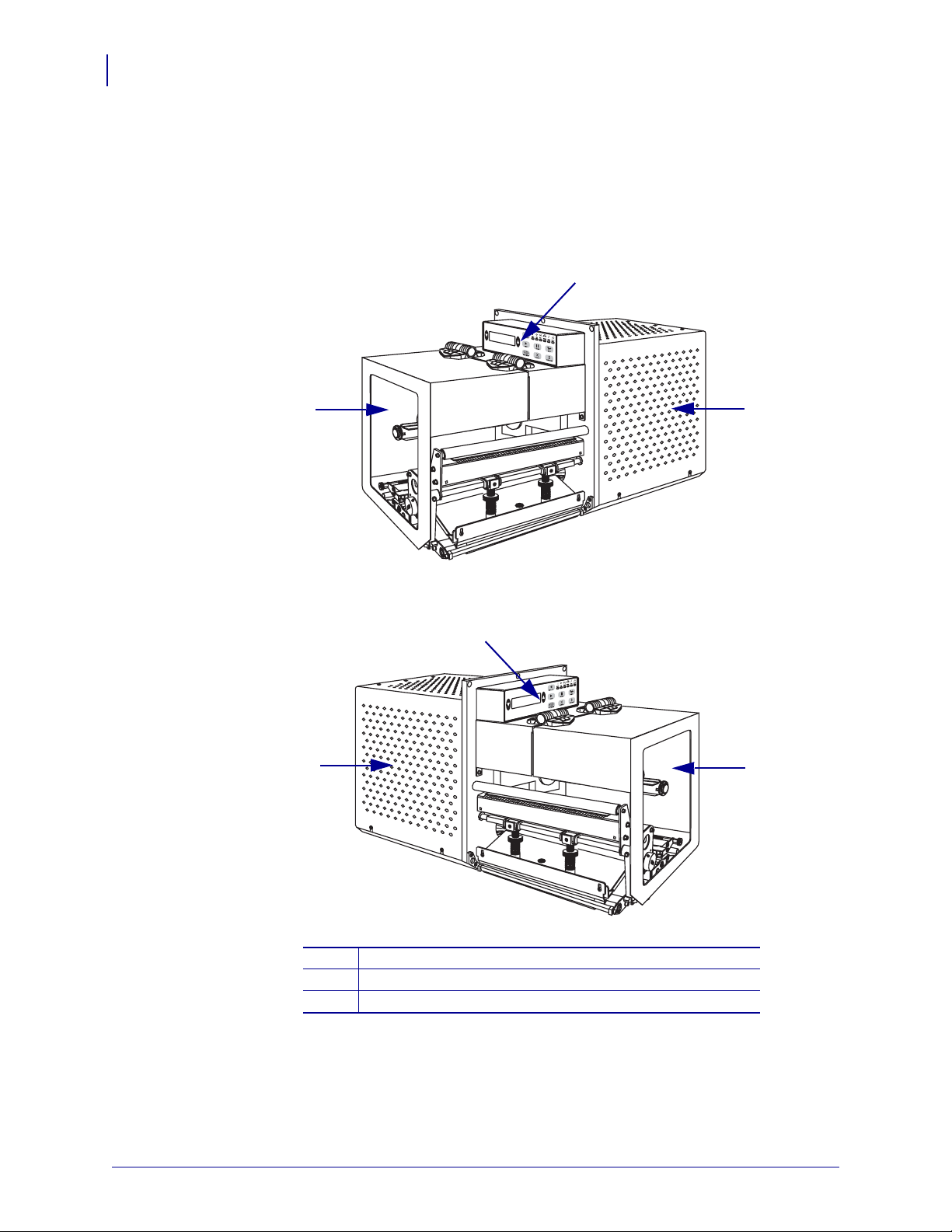
Print Engine Exterior View
Print Engine Exterior View
Print engines are available in a right-hand configuration (media moves from left to right,
Figure 27) and a left-hand configuration (media moves from right to left, Figure 28).
Figure 27 • Right-Hand (RH) Print Engine
2
1
3
Figure 28 • Left-Hand (LH) Print Engine
2
3
1
Media door
1
Control panel
2
Electronics cover
3
57517L-002 Rev. A 170PAX4 Quick Reference Guide 6/28/07
Page 3
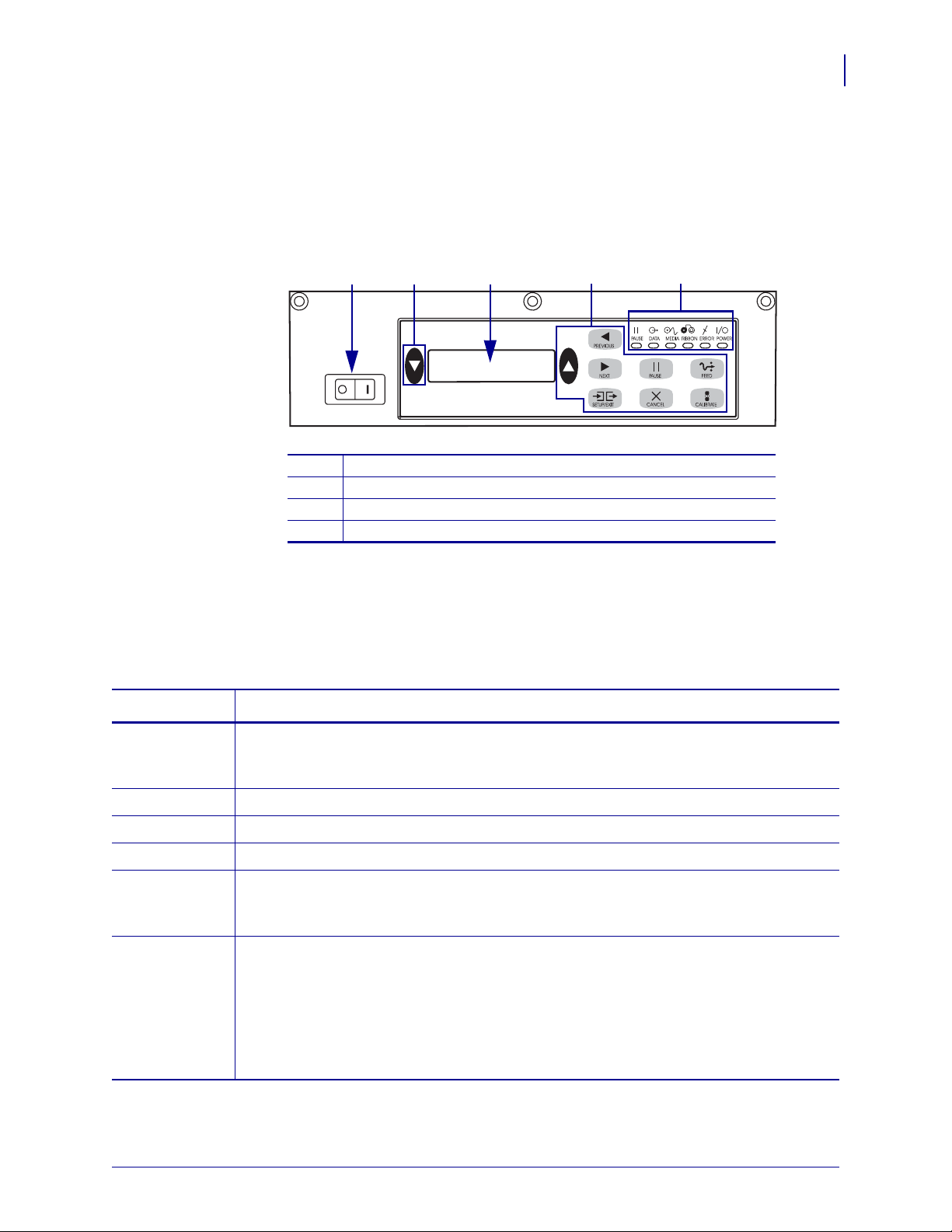
Control Panel
All controls and indicators for the print engine are located on the control panel (Figure 29).
The power switch is located to the side of the control panel.
170PAX4 Quick Reference Guide
Figure 29 • Control Panel (Right Hand)
Control Panel
3
1
Power switch
1
Buttons
2
Liquid Crystal Display (LCD)
3
Lights/LEDs
4
Control Panel Buttons
The control panel buttons are described in Table 7.
Table 7 • Control Panel Buttons
Button Description/Function
3 242
BLACK
OVALS
The two black ovals are used to change parameter values for a parameter being displayed
on the LCD. Common uses include increasing or decreasing a value, answering yes or no,
indicating ON or OFF, and scrolling through choices.
PREVIOUS Scrolls the LCD to the previous parameter.
NEXT Scrolls the LCD to the next parameter.
SETUP/EXIT Enters and exits configuration mode.
PAUSE Stops and restarts the printing process or removes error messages and clears the LCD. If a
label is printing, it is completed before the printing process stops. When the print engine is
paused, the PAUSE light is ON.
CANCEL
CANCEL functions only in Pause mode. Pressing CANCEL has these effects:
• Cancels the label format that is currently printing.
• If no label format is printing, the next one to be printed is canceled.
• If no label formats are waiting to be printed,
To clear the print engine’s entire label format memory, press and hold
CANCEL is ignored.
CANCEL until the
DATA light turns off.
6/28/07 170PAX4 Quick Reference Guide 57517L-002 Rev. A
Page 4

170PAX4 Quick Reference Guide
4
Control Panel
Table 7 • Control Panel Buttons (Continued)
Button Description/Function
FEED Feeds a blank label.
• If the print engine is idle or paused, the label is fed immediately.
• If the print engine is printing, the label is fed after the current batch prints.
CALIBRATE
CALIBRATE functions only in Pause mode. Press CALIBRATE to recalibrate for proper
media length, to set media type (continuous/non-continuous), and to set print method
(direct thermal/thermal transfer).
Control Panel Indicator Lights (LEDs)
The control panel lights are described in Table 8.
Table 8 • Control Panel Lights
LED
POWER
(Green)
PAUSE
(Yellow)
OFF Indicates ON Indicates FLASHING Indicates
Print engine is
OFF, or no power
Power switch is ON, and power is being
supplied to print engine.
to print engine.
Normal operation. One of the following:
• Print engine is paused because of an
error condition (printhead, ribbon, or
paper error). Usually occurs in
conjunction with another LED.
PAUSE was pressed.
•
• A pause was requested from the
Applicator Port.
• A pause was received as part of the
label format.
—
—
DATA
(Green)
No data being
received or
processed.
Data is processing or printing is taking
place. No data is being received.
Print engine is receiving data
from or sending status
information to the host
computer.
MEDIA
(Yellow)
RIBBON
(Yellow)
Normal operation.
Media properly
loaded.
Normal operation.
Ribbon properly
loaded.
Out of media. (Print engine is paused,
LCD displays error message, and
PAUSE light is ON).
Ribbon in when print engine is in direct
thermal mode, or no ribbon in when print
engine is in thermal transfer mode. Print
—
—
engine is paused, LCD displays error
message, and PAUSE light is ON .
ERROR
(Orange)
57517L-002 Rev. A 170PAX4 Quick Reference Guide 6/28/07
No print engine
errors.
— Print engine error exists.
Check the LCD for status.
Page 5
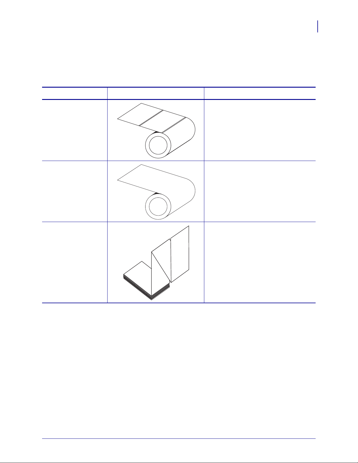
Media
The print engine can use various types of media (Table 9).
Table 9 • Types of Media
Media Type How It Looks Description
170PAX4 Quick Reference Guide
Media
5
Non-Continuous Roll
Media
Continuous
Roll Media
Fanfold Media The media is folded in a zigzag pattern.
The media is wound on a core. Individual
labels are separated by a gap, notch, hole,
or black mark, which enables you to see
where one label ends and the next one
begins. When using media that has holes or
notches, position the media sensor directly
over a hole or notch.
The media is wound on a core and is
without gaps, holes, notches, or black
marks. This allows the image to be printed
anywhere on the label.
6/28/07 170PAX4 Quick Reference Guide 57517L-002 Rev. A
Page 6
170PAX4 Quick Reference Guide
6
Ribbon
Ribbon
Ribbon is a thin film that is coated on one side with wax or wax resin, which is transferred to
the media during the thermal transfer process.
When To Use Ribbon
Thermal transfer media requires ribbon for printing while direct thermal media does not.
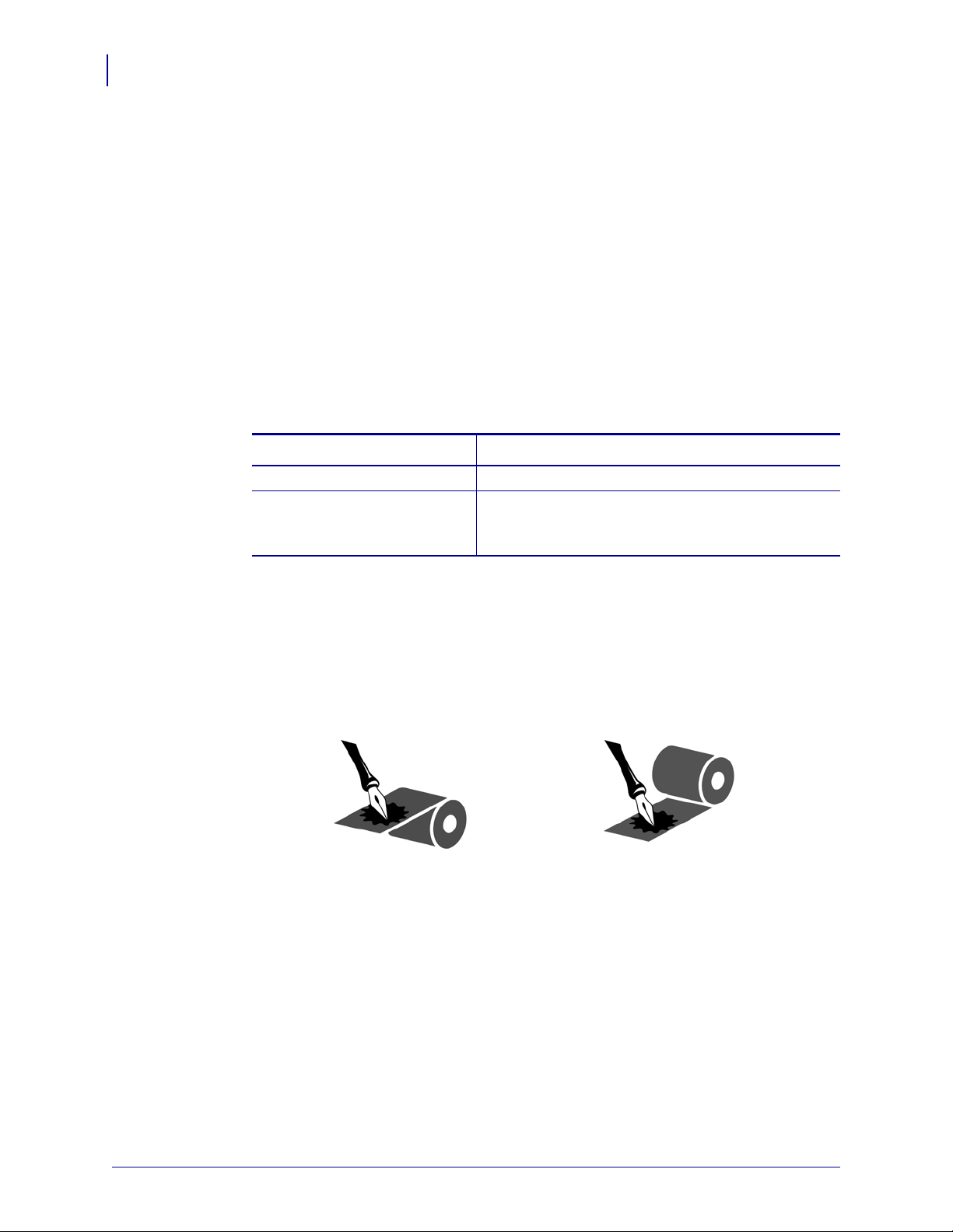
To determine if ribbon must be used with a particular media, perform a media scratch test.
To perform a media scratch test, complete these steps:
1. Sc ratch the print surface of the media with your fingerna il.
2. Did a bl ack mark appear on the media?
If a black mark... Then the media is...
Does not appear on the media Thermal transfer. A ribbon is required.
Appears on the media Direct thermal. No ribbon is re quired, though ribbon
may be used to help protect the printhead from
abrasion with the media.
Coated Side of Ribbon
Ribbon can be wound with the coated side on the inside or outside (Figure 30). This print
engine can only use ribbon that is coated on the outside.
Figure 30 • Ribbon Coated on Outside or Inside
To determine which side of a ribbon is coated, complete these steps:
1. Peel a label from its liner.
2. Press a corner of the sticky side of the label to the outer surface of the roll of ribbon.
3. Peel the label off of the ribbon.
Outside Inside
57517L-002 Rev. A 170PAX4 Quick Reference Guide 6/28/07
Page 7

170PAX4 Quick Reference Guide
Ribbon
4. Observe the results. Did flakes or particles of ink from the ribbon adhere to the label?
If ink from the ribbon... Then...
Adhered to the label The ribbon is coated on the outer surface.
Did not adhere to the label The ribbon is coated on the inner surface. To verify this,
repeat the test on the inner surface of the roll of ribbon.
7
6/28/07 170PAX4 Quick Reference Guide 57517L-002 Rev. A
Page 8
170PAX4 Quick Reference Guide
8
Load Media
Load Media
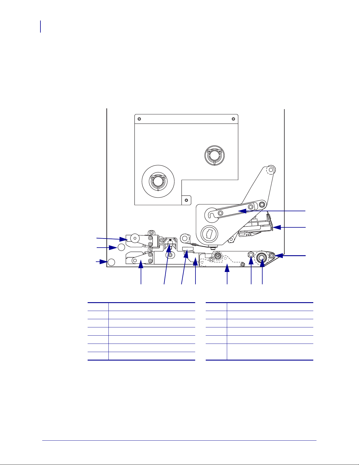
Figure 31 identifies the media-handling components of a right-hand print engine. A left-hand
unit contains a mirror image of these components. Figure 32 on page 9 shows both print
engines with media loaded.
Figure 31 • Components for Media Loading (Right-Hand)
13
12
11
Printhead latch
1
Printhead assembly
2
Peel bar
3
Platen roller
4
Printhead locking pin
5
Peel roller assembly
6
Peel roller latch
7
1
2
3
589 6
710
Media guide
8
Pinch roller assembly
9
Label guide shelf assembly
10
Lower guide post
11
Upper guide post
12
Top media sensor track assembly
13
4
57517L-002 Rev. A 170PAX4 Quick Reference Guide 6/28/07
Page 9
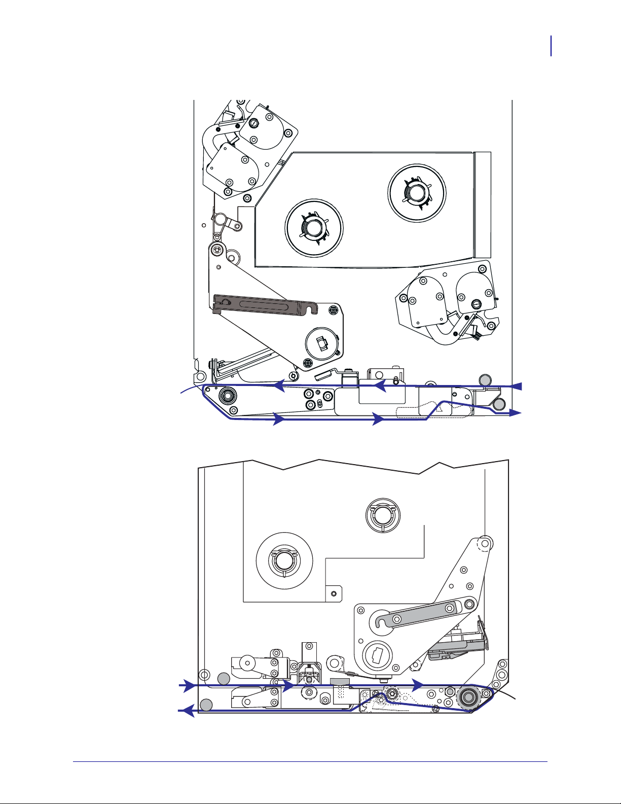
Figure 32 • Loaded Media
Left-Hand
170PAX4 Quick Reference Guide
Load Media
9
Right-Hand
6/28/07 170PAX4 Quick Reference Guide 57517L-002 Rev. A
Page 10
170PAX4 Quick Reference Guide
10
Load Media
Caution • When you are loading media or ribbon, remove all jewelry that could come into
contact with the printhead or other printer parts.
To load media, complete these steps:
1. Load media on the media supply reel of the applicator (refer to the applicator ’s user
guide).
2. Op en the media door.
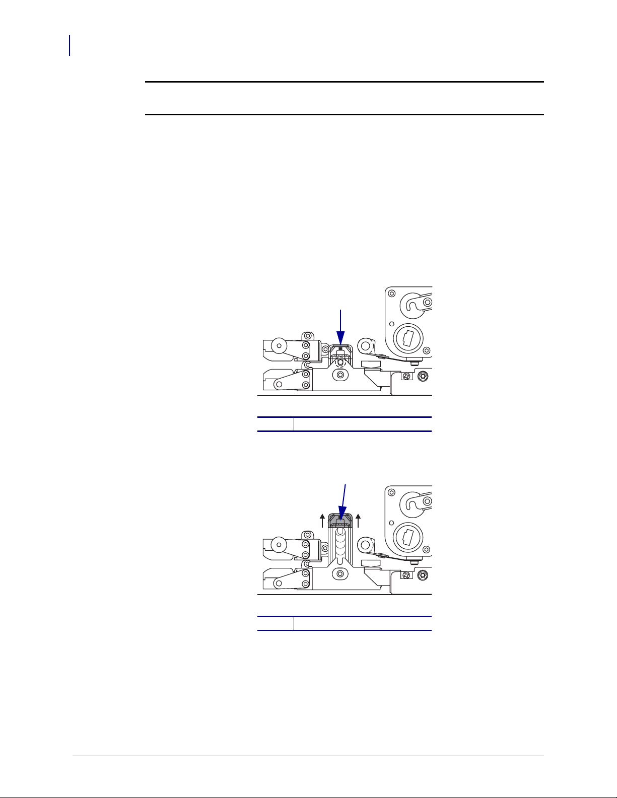
3. See Figure 33. Press down on the pinch roller release latch.
The pinch roller assembly springs up (Figure 34).
Figure 33 • Pressing the Pinch Roller Release Latch
1
Pinch roller release latch
1
Figure 34 • Opened Pinch Roller Assembly
1
Pinch roller assembly
1
57517L-002 Rev. A 170PAX4 Quick Reference Guide 6/28/07
Page 11

170PAX4 Quick Reference Guide
Load Media
4. See Figure 35. Under the print engine, grasp the brass thumb nut of the outer media guide,
and slide the outer media guide all the way out.
Figure 35 • Sliding the Outer Media Guide
1
11
Brass thumb nut
1
Outer media guide
2
2
6/28/07 170PAX4 Quick Reference Guide 57517L-002 Rev. A
Page 12

170PAX4 Quick Reference Guide
12
Load Media
5. See Figure 36. Open the printhead assembly by unlatching the printhead latch from the
locking pin.
Caution • The printhead may be hot and could cause severe burns. Allow the printhead
to cool.
Figure 36 • Opening the Printhead Assembly
1
Printhead latch
1
Locking pin
2
2
57517L-002 Rev. A 170PAX4 Quick Reference Guide 6/28/07
Page 13

170PAX4 Quick Reference Guide
Load Media
6. See Figure 37. Thread the media through the upper media path as follows:
a. Under the upper guide post
b. Between the top media sensor track assembly and the label guide shelf assembly
c. Below the pinch roller assembly
d. Under the printhead assembly
7. See Figure 37. Extend approximately 30 in. (75 cm) of media past the peel bar. Remove
and discard the labels from this exposed media.
Figure 37 • Threading the Media
13
1 4
Upper guide post
1
Top media sensor track assembly
2
Label guide shelf assembly
3
Pinch roller assembly
4
Printhead assembly
5
Peel bar
6
Liner
7
Label
8
2 3
5
6
7
8
6/28/07 170PAX4 Quick Reference Guide 57517L-002 Rev. A
Page 14

170PAX4 Quick Reference Guide
14
Load Media
8. See Figure 38. Position the media so that it is aligned with and just touching the inner
media guide.
9. See Figure 38. Under the print engine, grasp the brass thumb nut of the outer media guide,
and position the outer media guide so that it just touches the outer edge of the media.
Figure 38 • Adjusting the Outer Media Guide
1
2
Outer media guide
1
Media
2
10. See Figure 33 on page 10. Press down on the pinch roller assembly until it locks closed.
11. See Figure 36 on page 12. Close the printhead assembly by rotating the printhead latch
until it latches onto the locking pin.
12. See Figure 39. Raise the peel roller latch so that the peel roller assembly pivots downward.
Figure 39 • Releasing the Peel Roller Assembly
1
2
Peel roller latch
1
Peel roller assembly
2
57517L-002 Rev. A 170PAX4 Quick Reference Guide 6/28/07
Page 15

170PAX4 Quick Reference Guide
Load Media
13. See Figure 40. Thread the media liner around the peel bar, under the platen roller, and
through the peel roller assembly.
Note • If the applicator has an air tube, route the media liner between the air tube and the
peel bar. Do not thread the med ia lin er ove r the air tu be.
Figure 40 • Threading the Liner
15
4
Peel bar
1
Platen roller
2
Peel roller assembly
3
Lower guide post
4
14. See Figure 41. Rotate the peel roller assembly up until it locks into the closed position.
Figure 41 • Closed Peel Roller Assembly
1
2
3
15. See Figure 40. Thread the media liner under the lower guide post and around the take-up
spindle of the applicator (refer to the applicator’s user guide).
16. Close the media door.
6/28/07 170PAX4 Quick Reference Guide 57517L-002 Rev. A
Page 16

170PAX4 Quick Reference Guide
16
Load Ribbon
Load Ribbon
Use ribbon with thermal transfer media (see Ribbon on page 6). The ribbon must be coated on
the outside and wider than the media. If the ribbon is narrower than the media, areas of the
printhead are unprotected and subject to premature wear.
Figure 42 identifies the ribbon system components inside the media compartment of a
right-hand print engine. A left-hand unit contains a mirror image of these components.
Figure 43 on page 17 shows the print engine with ribbon loaded.
Figure 42 • Components for Ribbon Loading
1 2
Ribbon supply spindle
1
Ribbon take-up spindle
2
Upper ribbon guide roller
3
Printhead latch
4
3
4
5
7
5
6
7
6
Printhead assembly
Locking pin
Lower ribbon guide roller
57517L-002 Rev. A 170PAX4 Quick Reference Guide 6/28/07
Page 17

170PAX4 Quick Reference Guide
Figure 43 • Loaded Ribbon
Left-Hand
Load Ribbon
17
Right-Hand
6/28/07 170PAX4 Quick Reference Guide 57517L-002 Rev. A
Page 18

170PAX4 Quick Reference Guide
18
Load Ribbon
Caution • When you are loading media or ribbon, remove all jewelry that could come into
contact with the printhead or other printer parts.
To load ribbon, complete these steps:
1. See Figure 44. Place a full ribbon roll onto the ribbon supply sp in dle so th e ri bb on rot ates
as shown, and then push the roll toward the print engine frame until it is fully seated.
Figure 44 • Placing Ribbon on the Ribbon Supply Spindle
Left-Hand Right-Hand
1
Ribbon supply spindle with ribbon
1
1
57517L-002 Rev. A 170PAX4 Quick Reference Guide 6/28/07
Page 19

170PAX4 Quick Reference Guide
Load Ribbon
2. See Figure 45. Open the printhead assembly by unlatching the printhead latch from the
locking pin.
Figure 45 • Opening the Printhead Assembly
1
2
19
Printhead latch
1
Locking pin
2
3. See Figure 46. Thread the ribbon under the lower ribbon guide roller.
4. See Figure 46. Make sure that the ribbon passes directly below the ribbon sensor, which is
located near the back wall of the print engine.
Figure 46 • Threading Ribbon under the Ribbon Sensor
21
Lower ribbon guide roller
1
Ribbon sensor
2
6/28/07 170PAX4 Quick Reference Guide 57517L-002 Rev. A
Page 20

170PAX4 Quick Reference Guide
20
Load Ribbon
5. See Figure 47. Thread the ribbon under the printhead assembly and th en arou nd th e upp er
ribbon guide roller.
Caution • The printhead may be hot and could cause severe burns. Allow the printhead
to cool.
Figure 47 • Threading Ribbon under the Printhead Assembly
1
2
Upper ribbon guide roller
1
Printhead assembly
2
57517L-002 Rev. A 170PAX4 Quick Reference Guide 6/28/07
Page 21

170PAX4 Quick Reference Guide
Load Ribbon
6. See Figure 48. Place an empty ribbon core onto the ribb on take-up spindle, and then push
the core toward the print engine frame until it is fully seated.
7. See Figure 48. Attach the end of the ribbon to the empty ribbon core with adhesive tape or
a label, and wind for several turns in the direction shown. Ensure that the ribbon winds
evenly on the spindle.
Figure 48 • Loading Ribbon on the Ribbon Take-Up Spindle
Left-Hand Right-Hand
21
1
Ribbon take-up spindle with empty ribbon core
1
8. See Figure 45 on page 19. Close the printhead assembly by pivoting the printhead latch
1
onto the locking pin.
9. Close the media door.
6/28/07 170PAX4 Quick Reference Guide 57517L-002 Rev. A
Page 22

170PAX4 Quick Reference Guide
22
Remove Used Ribbon
Remove Used Ribbon
To remove used ribbon, complete these steps:
1. Op en the media door.
2. Di d the ribbon run out?
If... Then...
Yes a. Remove the empty core from the ribbon supply spindle. Save the
No
core to use on the ribbon take-up spindle when you load ribbon.
b. Remove the used ribbon and core from the ribbon take-up spindle.
c. Install new ribbon following the instructions in Load Ribbon
on page 16.
a. Cut the ribbon near the ribbon take-up spindle.
b. Remove the used ribbon and core from the ribbon take-up spindle.
c. Locate an empty ribbon core. If necessary, remove and discard the
used ribbon from the core removed in the previous step.
d. See Figure 48 on page 21. Install the empty ribbon core onto the
ribbon take-up spindle, and push the core toward the print engine
frame until it is fully seated.
e. Thread the remaining ribbon on the ribbon supply spindle following
the instructions in Load Ribbon on page 16.
f. See Figure 48 on page 21. Attach the end of the ribbon to the empty
ribbon core with adhesive tape or a label, and wind for several turns
in the direction shown. Ensure that the ribbon win ds evenly on the
spindle.
57517L-002 Rev. A 170PAX4 Quick Reference Guide 6/28/07
Page 23

Configure the Print Engine
After you have installed the media and ribbon, you may set print engine parameters for your
application using the control panel.
Important • Certain printing conditions may require you to adjust printing parameters, such
as print speed, darkness, or print mode. These conditions include (but are not limited to):
• printing at high speeds
• peeling the media
• the use of extremely thin, small, synthetic, or coated labels
Because print quality is affected by these and other factors, run tests to determine the best
combination of printer settings and media for your applic ation. A po or match may limit p rint
quality or print rate, or the print engine may not funct ion properly in the desired print mode.
To enter Setup Mode, complete these steps:
1. On the control panel, press SETUP/EXIT.
170PAX4 Quick Reference Guide
Configure the Print Engine
23
2. Press either NEXT or PREVIOUS to scroll through the parameters.
To leave Setup Mode, complete these steps:
1. Press SETUP/EXIT.
The LCD displays
2. Press the left or right oval to display the save options (Table 10).
LCD
PERMANENT
TEMPORARY
CANCEL
LOAD DEFAULTS
LOAD LAST SAVE
SAVE CHANGES.
Table 10 • Save Options When Leaving Setup Mode
Description
Stores values in the print engine even when power is turned
off.
Saves the changes until power is turned off.
Cancels all changes from the time you pressed SETUP/EXIT
except for any made to the darkness and tear-off settings.
Restores all parameters other than the network settings b ack to
the factory defaults.
Note • Loading factory defaults causes the print engine
to auto-calibrate.
Loads values from the last permanent sav e.
DEFAULT NET
3. Press NEXT to select the displayed choice.
When the configuration and calibration sequence is done,
6/28/07 170PAX4 Quick Reference Guide 57517L-002 Rev. A
Restores the wired and wireless network settings back to
factory defaults.
PRINTER READY displays.
Page 24

170PAX4 Quick Reference Guide
24
Configure the Print Engine
Print a Configuration Label
When you have loaded the media and ribbon (if necessary), print a configuration label as a
record of your print engine’s current settings. Keep the label to use when troubleshooting
printing problems.
To print a configuration label, complete these steps:
1. On the control panel, press SETUP/EXIT.
2. Press NEXT or PREVIOUS to scroll through the parameters until you reach
LIST SETUP.
3. Press the right oval to confirm printing.
A configuration label prints (Figure 49).
Figure 49 • Configuration Label
57517L-002 Rev. A 170PAX4 Quick Reference Guide 6/28/07
Page 25

Print a Network Configuration Label
If you are using a print server, you can print a network configuration label after the printer is
connected to the network.
To print a network configuration label, complete these steps:
1. On the control panel, press SETUP/EXIT.
2. Press NEXT or PREVIOUS to scroll through the parameters until you reach
LIST NETWORK.
3. Press the right oval to confirm printing.
A network configuration label prints (Figure 50). If no wireless print server is installed,
the wireless portion of the label does not print.
Figure 50 • Network Configuration Label
170PAX4 Quick Reference Guide
Configure the Print Engine
25
6/28/07 170PAX4 Quick Reference Guide 57517L-002 Rev. A
Page 26

170PAX4 Quick Reference Guide
26
Configure the Print Engine
View or Change Parameters
Table 11 shows a subset of the print engine parameters in the order in which they are displayed
when you press
continue to the next parameter, or press
cycle. When a parameter is changed, an asterisk (*) is shown in the upper left corner of the
display to indicate that the value is different from the one currently active in the print engine.
Parameter Action/Explanation
NEXT after entering setup mode. Throughout this process, press NEXT to
PREVIOUS to return to the previous parameter in the
Table 11 • Print Engine Parameters
DARKNESS
- 4.0 +
PRINT SPEED
2 IPS
SLEW SPEED
6 IPS
Adjusting Print Darkness
If printing is too light or if there are voids in printed areas, increase the
darkness. If printing is too dark or if there is spreading or bleeding of
printed areas, decrease the darkness. Darkness settings also may be
changed by the driver or software settings.
Important • Set the darkness to the lowest setting that provides good print
quality. If the darkness is set too high, the ink may smear, the ribbon may
burn through, or the printhead may wear prematurely.
• Press the right oval to increase darkness.
• Press the left oval to decrease darkness.
Default: +4.0
Range: 00.0 to +30.0
Adjusting Print Speed
• Press the right oval to increase value.
• Press the left oval to decrease value.
Default: 2 IPS
Range: 2 to 12 IPS for 203 dpi, 2 to 8 IPS for 300 dpi
Adjusting Slew Speed
• Press the right oval to increase value.
• Press the left oval to decrease value.
Default: 6 IPS
Range: 1 to 12 IPS
BACKFEED SPEED
2 IPS
57517L-002 Rev. A 170PAX4 Quick Reference Guide 6/28/07
Adjusting Backfeed Speed
• Press the right oval to increase value.
• Press the left oval to decrease value.
Default: 2 IPS
Range: 1 to 12 IPS
Page 27

170PAX4 Quick Reference Guide
Table 11 • Print Engine Parameters (Continued)
Configure the Print Engine
27
Parameter
TEAR OFF +000
- +
PRINT MODE
TEAR-OFF
MEDIA TYPE
NON-CONTINUOUS
Action/Explanation
Adjusting the Tear-Off Position
Establishes the position of the media over the tear-off/peel-off bar after
printing. Positive numbers move the media out and negative numbers move
the media in.
Each press of an oval adjusts the tear-off position by four dot rows.
• Press the right oval to increase value.
• Press the left oval to decrease value.
Default: +0
Range: –120 to +120
Selecting Print Mode
Print mode settings tell the print engine the method of media delivery that
you wish to use.
• Press either oval to display choices.
Default: TEAR-OFF
Selections: TEAR-OFF, REWIND, APPLICATOR
Setting Media Type
T ells the print engi ne the type of media that you are usi ng. When you select
non-continuous media, the print engine feeds media to calculate label
length (the distance between two recognized registration points of the
interlabel gap or alignment notch or hole). When you select continuous
media, you must include a label length instruction in your label format
^LLxxxx if you are using ZPL or ZPL II).
(
• Press either oval to display choices.
Default: NON-CONTINUOUS
Selections: CONTINUOUS, NON-CONTINUOUS
SENSOR TYPE
WEB
PRINT METHOD
THERMAL-TRANS.
6/28/07 170PAX4 Quick Reference Guide 57517L-002 Rev. A
Setting the Sensor Type
Tells the print engine whether you are using media web media (label
separations indicated by a gap, notch, or hole) or media with black
registration marks printed on the back.
• Press either oval to display other choices.
Default: WEB
Selections: WEB, MARK
Selecting Print Method
T ells the print engine the method of printing to use: thermal transfer (ribbon
required) or direct thermal (no ribbon).
• Press either oval to display choices.
Default: Thermal transfer
Selections: Thermal transfer, direct thermal
Note • Selecting direct thermal when using ribbon creates a print
engine error condition, but printing continues.
Page 28

170PAX4 Quick Reference Guide
28
Configure the Print Engine
Table 11 • Print Engine Parameters (Continued)
Parameter
PRINT WIDTH
168 0/8 MM +
MAXIMUM LENGTH
-39.0 IN 988 MM+
Action/Explanation
Setting Print Width
Determines the printable area across the width of the label given the
resolution of the print engine.
T o change value shown:
1. Press the left oval to move the cursor.
2. Press the right oval to increase the value of the digit.
To change the unit of measurement:
1. Press the left oval until the unit of measurement is active.
2. Press the right oval to toggle to a different unit of measure (mm,
inches, or dots).
Default: 168 0/8 mm for 203 dpi print engines; 168 0/12 mm for 300 dpi
print engines
NOTE: Setting the width too narrow can result in portions of the label not
being printed on the media. Setting the width too wide wastes formatting
memory and can cause printing off the label and on the platen roller. This
setting can affect the horizontal position of the label format if the image
was inverted using the
Setting Maximum Label Length
The maximum label length is used during the calibration process. Interlabel
gap is considered part of the label length.
Always set a value that is at least 1 in. (25.4 mm) longer than the length of
the label you are using. For example, if the label length is 5 in. (126 mm)
including the interlabel gap, set the parameter for 6.0 in. (152 mm). If the
value is set to a smaller value than the label length, the print engine
assumes that continuous media is loaded, and the print engine cannot
calibrate.
• To increase the value, press the right oval.
• To decrease the value, press the left oval.
Default: 39.0 in. (988 mm).
Range: Values are adjustable in 1 in. (25.4 mm) increments.
^POI ZPL II command.
LIST FONTS
PRINT
LIST BAR CODES
PRINT
LIST IMAGES
PRINT
57517L-002 Rev. A 170PAX4 Quick Reference Guide 6/28/07
List Fonts
• Press the right oval to print a label that lists the standard fonts and any
optional fonts in stored in the print engine’s RAM, Flash memory, or
optional PCMCIA font cards.
List Bar Codes
• Press the right oval to print a label that lists the available bar codes i n the
print engine. Bar codes may be stored in RAM, Flash memory, or
optional PCMCIA cards.
List Images
• Press the right oval to print a label that lists the available images stored
in the print engine’s RAM, Flash memory, or optional memory card.
Page 29

170PAX4 Quick Reference Guide
Table 11 • Print Engine Parameters (Continued)
Configure the Print Engine
29
Parameter
LIST FORMATS
PRINT
LIST SETUP
PRINT
LIST NETWORK
PRINT
LIST ALL
PRINT
LANGUAGE
ENGLISH
Action/Explanation
List Formats
• Press the right oval to print a label that lists the available formats stored
in the print engine’s RAM, Flash memory, or optional memory card.
List Setup
• Press the right oval to print a configuration label, which lists the current
print engine configuration.
List Network Settings
• Press the right oval to print a network configuration labe l, which lists the
settings for any print servers that are installed.
List All
• Press the right oval to print labels that list the available fonts, bar codes,
images, formats, and the current print engine and network
configurations.
Selecting the Display Language
This parameter allows you to change the language displayed on the control
panel LCD.
• Press the right or left oval to display other choi ces.
Default: ENGLISH
Selections: ENGLISH, SPANISH, FRENCH, GERMAN, ITALIAN,
NORWEGIAN, PORTUGUESE, SWEDISH, DANISH, SPANISH 2,
DUTCH, FINNISH, CUSTOM
6/28/07 170PAX4 Quick Reference Guide 57517L-002 Rev. A
Page 30

170PAX4 Quick Reference Guide
30
Cleaning Schedule
Cleaning Schedule
The recommended cleaning schedule is shown in Table 12. See the following pages for
specific procedures.
Caution • Use only the cleaning agents indicated. Zebra is not responsible for damage
caused by any other fluids being used on this printer.
Table 12 • Recommended Printer Cleaning Schedule
Area Method Interval
Printhead Solvent* Perform these procedures at the following times:
Platen roller Solvent*
Transmissive media sensor Air blow
Reflective media sensor Air blow
Media path Solvent*
Ribbon sensor Air blow
• When CLEAN HEAD NOW appears.
• Direct Thermal Print Mode: After every roll of
labels or 500 ft (150 m) of fanfold labels.
• Thermal Transfer Print Mode: After every roll
(1500 ft or 450 m ) of ribbon.
Door-open sensors Air blow Monthly
Tear-off/pe e l-o ff bar Solvent*
* Use Zebra’s Preventative Maintenance kit, part number 47362, or a solution of 90% isopropyl alcohol and
10% deionized water.
Clean the Printhead and Platen Roller
Clean the printhead and platen roller according to the schedule in Table 12 on page 30. Clean
the printhead more often if you see inconsistent p rint quality, such as voids or light print. Clean
the platen roller if you see media movement problems.
Caution • The printhead may be hot and could cause severe burns. Allow the printhead
to cool.
Caution • Observe proper electrostatic safety precautions when handling any
static-sensitive components such as circuit boards and printheads.
Caution • When you are loading media or ribbon, remove all jewelry that could come into
contact with the printhead or other printer parts.
To clean the printhead and platen roller, complete these steps:
1. Turn off (O) the print engine.
57517L-002 Rev. A 170PAX4 Quick Reference Guide 6/28/07
Page 31

170PAX4 Quick Reference Guide
Cleaning Schedule
2. See Figure 51. Open the printhead assembly by unlatching the printhead latch from the
locking pin.
Figure 51 • Opening the Printhead Assembly
1
2
31
Printhead latch
1
Locking pin
2
3. Remove the media and ribbon from the print engine.
6/28/07 170PAX4 Quick Reference Guide 57517L-002 Rev. A
Page 32

170PAX4 Quick Reference Guide
32
Cleaning Schedule
4. See Figure 52. Using Preventative Maintenance Kit (part number 47362) or a solution of
90% isopropyl alcohol and 10% deionized water on a cotton swab, wipe the print elements
from end to end. Allow the solvent to evaporate.
Figure 52 • Printhead and Platen Roller Cleaning (Right-Hand Unit Shown)
1 2
3
Printhead elements (gray strip)
1
Cotton swab
2
Platen Roller
3
5. Use a lint-free cloth moistened with alcohol to clean the platen roller and other rollers.
Rotate the rollers while cleaning.
6. Reload the ribbon and media (if used).
7. Turn on (I) the print engine.
Note • If print quality does not improve after you perform this procedure, clean the printhead
with Save-a-Printhead cleaning film. Call your authorized Zebra distributor for more
information.
57517L-002 Rev. A 170PAX4 Quick Reference Guide 6/28/07
 Loading...