

Zebra S-Series
Maintenance Manual
Volume 1: General Maintenance
Zebra Technologies Corporation
333 Corporate Woods Parkway
Vernon Hills, IL, US A 60061-3109
Telephone: +1 (847) 634-6700
Fax: +1 (847) 913-8766
38452L Rev. 3 Copyright 1995 Zebra Technologies Corporation. All rights reserved.
Zebra Technologies Europe Limited
Zebra House
The Valley Cen tre, Gordan R oad
High Wycombe, Buckinghamshire
HP13 6EQ, UK
Telephone: +44 (0) 1494 472872
Fax: +44 (0) 1494 450103

R

Zebra S-Series Printer
Maintenance Manual
(Volume 1, Rev. 3)
Registration Form
ZEBRA TECHNOLOGIES CORPORATION
To receive Maintenance Manual revisions and updates,
complete this form and fax or mail it to Zebra Technologies
at the fax number or address shown below.
Company __________________________________________
Address ____________________________________________
City________________________________________________
State, Zip ___________________________________________
Phone # (_______) __________________________________
Contact: ___________________________________________
Zebra Technologies Corporation
333 Corporate Woods Parkway
Vernon Hills, Illinois, USA 60061-3109
ATTN: Technical Training
FAX Number: +1 (847) 913-8766

R

R
ii 38452L Rev. 3

TABLEOFCONTENTS
ComplianceandCopyrightStatements ..........i
THEZEBRAS-SERIESSYSTEM
Printer Specifications.....................1-1
MediaHandling......................1-1
PrintingConsiderations..................1-2
MediaConsiderations...................1-2
RibbonConsiderations..................1-3
Zebra Programming LanguageII(ZPLII
BarCodes.........................1-3
Standard Printer Fonts...................1-4
Physical Size.......................1-5
ElectricalRequirements..................1-6
CableRequirements....................1-6
115 VAC Applications..................1-6
230VAC Applications..................1-6
Environmental OperatingRange.............1-6
Communication Specifications................1-7
SerialDataCommunications Overview..........1-7
ParallelDataCommunicationsOverview.........1-9
®
).......1-3
GETTINGREADYTOPRINT
Controls andIndicators....................2-2
FrontPanelControls...................2-2
FrontPanelLEDs.....................2-3
MediaLoading........................2-4
RibbonLoading........................2-6
MediaCalibration.......................2-7
AdjustingthePrint Darkness.................2-7
AdjustingtheTear-Off Position................2-8
AdjustingthePosition of theTopof theLabel........2-9
AdjustingtheMediaSensor Positions............2-9
Upper MediaSensor....................2-9
Lower MediaSensor..................2-11
OptionSwitches.......................2-12
Bank 1..........................2-13
Bank 2..........................2-14
38452L Rev.3 iii

PRINTERDIAGNOSTICS
Power ON SelfTest......................3-1
Printer SelfTests.......................3-1
CANCELKeySelf Test..................3-3
PAUSEKeySelfTest...................3-4
FEED KeySelf Test....................3-5
MODE KeySelfTest...................3-6
FEED, PAUSEand CANCEL Keys...........3-6
PAUSEKeyand CANCEL Key.............3-7
FEED Keyand CANCELKey..............3-7
FEED Keyand PAUSEKey...............3-7
ExtendedPrinterDiagnostics.................3-9
PAUSEKeyLoopbackTest................3-9
FEED KeyLoopbackTest...............3-10
PREVENTIVEMAINTENANCE
Field MaintenanceFunctions.................4-1
Tools Required........................4-1
CleaningtheS-Seriesprinter.................4-1
CleaningthePrinthead....................4-2
CleaningtheSnapPlate....................4-2
CleaningtheCutterModule..................4-4
Lubricating theCutterModule................4-4
RecommendedPreventiveMaintenanceSchedule......4-5
CORRECTIVEMAINTENANCE
Tools Required........................5-2
TestEquipment Required...................5-2
105SPrintheadReplacement.................5-3
160SPrintheadReplacement.................5-5
Printhead Adjustments....................5-7
PrintQualityAdjustments.................5-7
Printhead Parallelism Adjustment.............5-8
Wear PlatePositionAdjustment..............5-9
Printhead Position Adjustment.............5-10
Printhead PressureAdjustment.............5-11
StripPlateAdjustment.................5-12
Printhead VoltageAdjustment................5-12
AdjustmentProcedure..................5-13
MediaSensor Position Adjustment.............5-15
ReflectiveSensorAdjustment................5-17
MediaSensor andRibbonSensorSensitivityAdjustment.5-17
TakeLabelSensor Alignment................5-19
iv 38452L Rev.3

MediaTrackingAdjustments................5-20
Rewind Mode......................5-20
Peel-Off Mode......................5-21
SpindleAdjustment and Maintenance...........5-22
TensionMeasurement Procedure............5-22
SpindleTensionAdjustment..............5-22
Removing theAdapterBoard................5-24
InstallingtheAdapterBoard................5-24
Removing theMain LogicandPower SupplyBoards...5-24
InstallingtheMainLogic and PowerSupplyBoards....5-28
EPROMSoftwareInstallation................5-29
MainDriveBelt— Removal, Replacement& Adjustment.5-31
Rewind DriveBelt—Removal,Replacement & Adjustment5-32
AC Power FuseReplacement................5-33
BatteryReplacement....................5-34
CutterAdjustmentsand Replacement Instructiions.....5-34
InternalAccess.....................5-35
CutterMotor Removal andInstallation.........5-35
CutterMechanicalAssemblyRemoval and Installation 5-37
Drive Link AssemblyInstallation............5-38
CutterCircuitBoardRemoval and Installation.....5-38
OpticalSensorRemoval andInstallation........5-39
Lower Drive Arm MechanicalAlignment.......5-39
Upper DriveArmAlignment..............5-40
TROUBLESHOOTING
Troubleshooting........................6-1
Power-ON Troubleshooting................6-1
GeneralTroubleshooting.................6-2
CutterModule Troubleshooting..............6-4
SampleLabels.........................6-5
FactoryAssistance.....................6-11
Returning Equipment....................6-11
105Sand160SMECHANICALDRAWINGSandPARTSLISTS
MechanicalPartsand Assemblies...............7-1
105SeMECHANICALDRAWINGSandPARTSLISTS
MechanicalPartsand Assemblies...............8-1
38452L Rev.3 v

R
vi 38452L Rev. 3

1 TheZebraS-SeriesSystem
Inthissection... Page
PrinterSpecifications.....................................................................1-1
MediaHandling.........................................................................1-1
PrintingConsiderations............................................................1-2
MediaConsiderations...............................................................1-2
RibbonConsiderations.............................................................1-3
ZebraProgrammingLanguageII(ZPLII
BarCodes...................................................................................1-3
StandardPrinterFonts..............................................................1-4
PhysicalSize..............................................................................1-5
ElectricalRequirements...........................................................1-6
CableRequirements..................................................................1-6
115VACApplications..............................................................1-6
230VACApplications..............................................................1-6
EnvironmentalOperatingRange............................................1-6
CommunicationSpecifications.....................................................1-7
SerialDataCommunicationsOverview.................................1-7
ParallelDataCommunicationsOverview.............................1-9
®
).........................1-3
PrinterSpecifications
Media Handling
• Tear-Offmode:Labelsareproducedinstrips.
• Rewindmode: RequiresMediaRewindoption.Labelsarer ewound
• Peel-Offmode: RequiresPeel-OffoptionorMediaRewindoption.
• Cuttermode RequiresCutterModuleoption(105Seonly).Mediaiscut
internallyontoa3"-inner-diametercardboardcore.
Labelsaredispensedandpeeledfromtheliner.The
linercanberewounddirectlyontothespindleusing
the“J”Hookorontoa3"-inner-diametercar dboardcore.
afterprinting;undersoftwarecontrol.
38452L Rev.3 Page1-1

S
-Series Maintenance Manual: Volume 1 TheS-Series System
Ribbon Considerations
Ribbon Specifications 105S/105
Ribbon width
To protect the printhead fromwear, Zebra recommends using
ribbon at least as wide as the media you are using.
Standard
lengths
Roll size Inner diameter of core 1.0" 25.4 mm 1.0" 25.4 mm
2:1 media to ribbon roll ratio 984 ft 300 m 984 ft 300 m
3:1 media to ribbon roll ratio 1476 ft 450 m 1476 ft 450 m
Outside diameter of full ribbon roll 3.2" 81.2 mm 3.2" 81.2 mm
Maximum 4.5" 114 mm 6.89" 175 mm
Minimum 0.75" 19 mm 2.0" 50.8 mm
Se
160
S
Zebra Programming Language II (ZPL II®)
• Downloadable graphic s
(with data compression)
• Bit image data transfer and printing,
including mixing of text and graphics
• Format inversion
• Mirror image printing
• Four-position field rotation
(0, 90, 180, 270 degrees)
• Slew command
• Programmable quantity with print pause
• Communicates in p rintable ASCII
characters
• Controlled via m ainframe, mini, PC,
Zebra-Mate or other data-entry device
• Serialized fields
• In-spec OCR-A and OCR-B
• UPC/EAN at nominal 100% magnification
(6 dot/mm and 12 dot/mm printheads only)
Bar Codes
The following bar codes are available:
• Code 11, Code 49, Code 93
• Code 39 (Supports ratios of 2:1, 3:1, 5:2,
and 7:3)
• Code 128 (Supports serialization in subsets B
and C and UCC Case C C o d es )
• CODABAR (Supports ratios of 2:1, 3:1 and
5:2)
• Interleaved 2 of 5 (Supports ratios of 2:1,
3:1 and 5:2; also supports Modulus 10
Check Digit)
• Industrial 2 of 5, Standard 2 of 5
• Plessey
• MSI
• CODABLOCK and MAXICODE
• E/EAN-8, E/EAN-13, EAN EXTENSIONS
• UPC-A, UPC-E, UPC EXTENSIONS
• PDF 417 and POSTNET
• Data Matrix
38452L Rev. 3 Page 1-3
TheS-Series System
Standard Printer Fonts
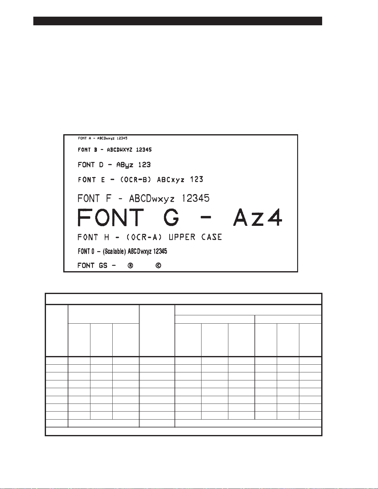
Fonts A, B, C, D, E, F, G, H, and GS are expandable up to 10 times, height- and
width-independent. However, fonts E and H (OCR-A and OCR-B) are not
considered “in-spec” when expanded.
The scal able smooth font Ø (CG Triumvirate™ Bold Condensed) is expandable
on a dot-by-dot basis, height- and-width independent, while maintaining smooth
edges. Maximum character size depends on the available memory.
IBM Code Page 850 international character sets are available in fonts A, B, C,
D, E, F, G, and Ø through software control.
S
-Series Maintenance Manual: Volume 1
Figure 1.1 Sample of Default Fonts
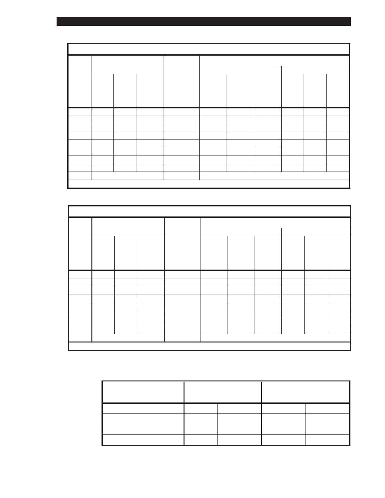
Font Matrices for 6 dots/mm Printhead (105S/105Seonly)
Font Matrix Type* Character Size
Inches Millimeters
gap
Height
A 9 5 1 U-L-D 0.059 0.039 25.40 1.50 1.00 1.00
B 11 7 2 U 0.072 0.059 16.93 1.83 1.50 0.67
C, D 18 10 2 U-L-D 0.118 0.079 12.70 3.00 2.00 0.50
E 21 10 3 OCR-B 0.138 0.085 11.72 3.50 2.17 0.46
F 26 13 3 U-L-D 0.171 0.105 9.53 4.33 2.67 0.38
G 60 40 8 U-L-D 0.394 0.315 3.18 10.00 8.00 0.13
H 17 11 4 OCR-A 0.112 0.098 10.16 2.83 2.50 0.40
GS 24 24 0 SYMBOL 0.157 0.157 6.35 4.00 4.00 0.25
Ø Default: 15 x 12 U-L-D Scalable
* U = Uppercase, L = Lowercase, D = Descenders
Page 1-4 38452L Rev. 3
Width
Inter-
character
Height
Width
Char./inch
Height
Width
Char./mm
S
-Series Maintenance Manual: Volume 1 TheS-Series System
Font Matrices for 8 dots/mm Printhead (105S, 105Seand 160S)
Font Matrix Type* Character Size
Inches Millimeters
gap
Height
A 9 5 1 U-L-D 0.044 0.029 33.90 1.13 0.75 1.33
B 11 7 2 U 0.054 0.044 22.60 1.38 1.13 0.89
C, D 18 10 2 U-L-D 0.088 0.059 16.95 2.25 1.50 0.67
E 28 15 5 OCR-B 0.138 0.098 10.17 3.50 2.50 0.40
F 26 13 3 U-L-D 0.128 0.079 12.71 3.25 2.00 0.50
G 60 40 8 U-L-D 0.295 0.236 4.24 7.50 6.00 0.17
H 21 13 6 OCR-A 0.103 0.093 10.71 2.63 2.38 0.42
GS 24 24 0 SYMBOL 0.118 0.118 8.48 3.00 3.00 0.33
Ø Default: 15 x 12 U-L-D Scalable
* U = Uppercase, L = Lowercase, D = Descenders
Width
Inter-
character
Height
Width
Char./inch
Height
Width
Char./mm
Font Matrices for 12 dots/mm Printhead (105S/105Se)
Font Matrix Type* Character Size
Inches Millimeters
gap
Height
A 9 5 1 U-L-D 0.029 0.016 50.80 0.73 0.40 2.00
B 11 7 2 U 0.036 0.023 33.86 0.91 0.58 1.34
C, D 18 10 2 U-L-D 0.059 0.033 25.40 1.49 0.83 1.00
E 42 20 6 OCR-B 0.138 0.066 23.44 3.50 1.67 0.92
F 26 13 3 U-L-D 0.185 0.042 19.06 2.15 1.06 0.76
G 60 40 8 U-L-D 0.198 0.132 6.36 5.02 3.35 0.26
H 34 22 8 OCR-A 0.112 0.072 20.32 2.84 1.82 0.80
GS 24 24 0 SYMBOL 0.079 0.079 12.70 2.00 2.00 0.50
Ø Default: 15 x 12 U-L-D Scalable
* U = Uppercase, L = Lowercase, D = Descenders
Width
Inter-
character
Height
Width
Char./ inch
Height
Physical Size
Physical
Characteristics 105
S
/105
Se
160S
Width
Char./mm
Height 15.4" 391 mm 15.4" 391 mm
Width 10.5" 267 mm 13.1" 333 mm
Depth 18.9" 480 mm 18.9" 480 mm
Weight (without options) 43 lbs. 19.5 kg 55 lbs. 24.9 kg
38452L Rev. 3 Page 1-5

TheS-Series System
Electrical Requirements
• 115VAC+15%/−20%or230VAC+15%/−15%,48-62Hz
• 5Amps@115V,3Amps@230V
• UL1950Listed-Certifiedt oCAN/CSA- C22.2No.950-M89
• ClassifiedtoIEC950andComplieswithFCCandCanadianDOCclass“A”rules
• CarriestheCEmarkofcompliance
Cable Requirements
TheACPowerCordhasathree-prongfemaleconnectorononeend.This
connectormustbepluggedintothematingcon nectorattherearoftheS-Seri es
printer.
115 VAC Applications
AStandardUS-style,three-pronggroundedmaleplugisattachedtotheother
endoftheACPowerCord.Thisconnectormustbepluggedintoanearby
electricaloutlet.
S
-Series Maintenance Manual: Volume 1
230 VAC Applications
AnACPowerCordmayormaynotbeincludedwiththeprinter.Forthose
locationsthatcannotuseeitherofthethreepowercordslistedbelow,aproper
groundedACPowerCordmustbeobtainedandinstalledbytheuser(SeeFigure
1.2).Thecablemustthenbepluggedintoanearbyelectricaloutlet.
Part Number ACPowerCableDescription
44618 Detachable Power Cord(US Standard 3-prongplug -115VAC)
44629 Detachable Power Cord(ContinentalEurope3-prongplug-230VAC)
44637 Detachable Power Cord(British 3-prongplug- 230VAC)
Figure1.2ACPowerCable
Environmental Ranges
Operating +41°Fto +104°F(+5°C to +40°C)
Temperature
Non-condensing
relativehumidity
Page1-6 38452L Rev.3
Storage -40°Fto +158°F(-40°Cto +70°C)
Operating 20%to 85%
Storage 20%to 85%
S
-Series Maintenance Manual: Volume 1 TheS-Series System
Communication Specifications
Both serial and parallel dat a communication interfaces are available for the
S-Series printers. The S-Series printer sends and receives standard ASCII
(American Standard Code for Information Interchange) data characters.
With ZPL II
communications. Refer to the user’s gui de for further information.
Serial Data Communications Overview
The S-S eries printers have a D ata Terminal Equipment (DTE) port that supports
RS-232 serial data communications. The RS-232 interf ace has a standard 25-pin
DB25-S connector located at the rear of the printer. For all RS-232 input and
output signals, the S-Series printer follows the EIA RS-232 and CCITT V.24
specifications for signal levels.
The baud rate, number of data bits, and parity are user-selectable via DIP
switches at the rear of the printer. Parity only applies to data transmitted by the
printer. The parity associated with received data is ignored. Further information
on the settings of these switches is contained in the printer’s user ’s guide.
®
, the Error Det ection Protocol feature provides virtually error-free
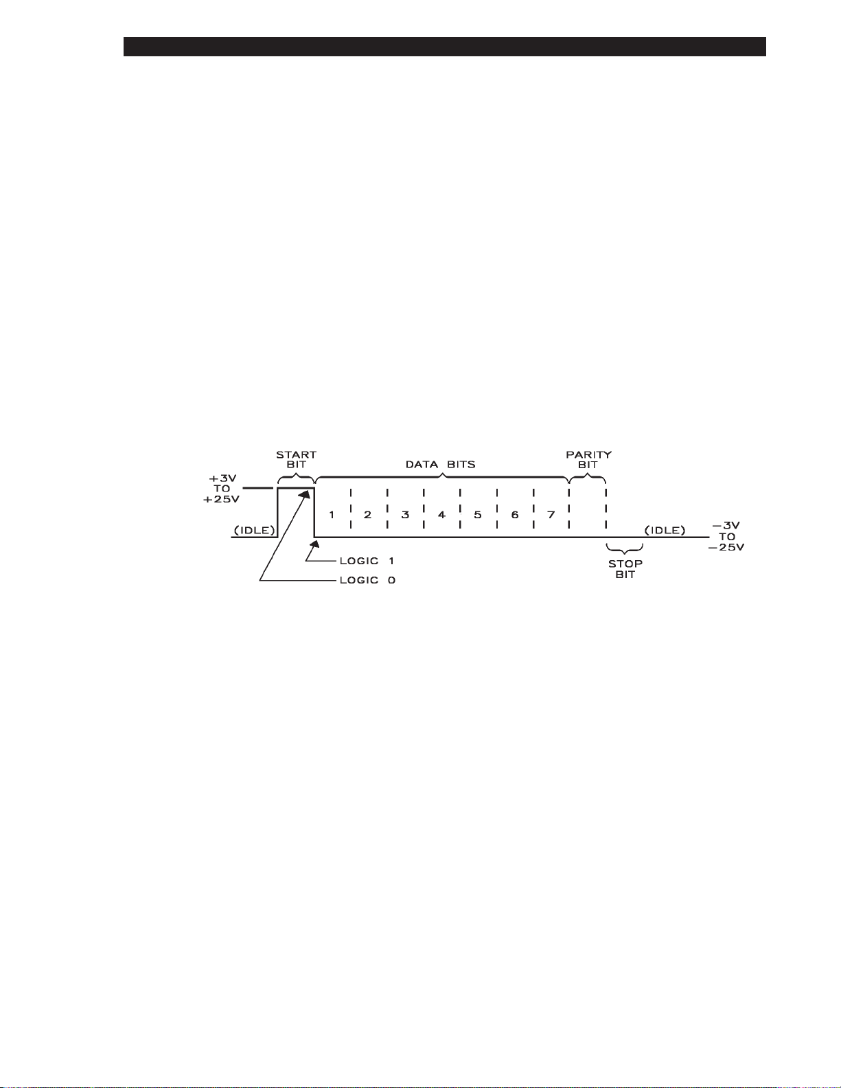
Figure 1.3 RS-232 Signal/ASCII Code Data Conditions
Serial Data Signal Levels
Serial data signals are defined as either MARK or SPACE, while control signals
are either ON or OFF. The output levels for the S-S eries printers are as follow s:
MARK or OFF = - 7 to - 10 Volts
SPACE or ON = +7 to +10 Volts
Serial Interface Connector Pinout and Description
A D B25-S connector is located at the rear of the Zebra S-Series printer and
provides serial data communications to a host using RS-232 signaling.
The pinout s and signal descriptions for the DTE port are as follows:
38452L Rev. 3 Page 1-7
TheS-Series System
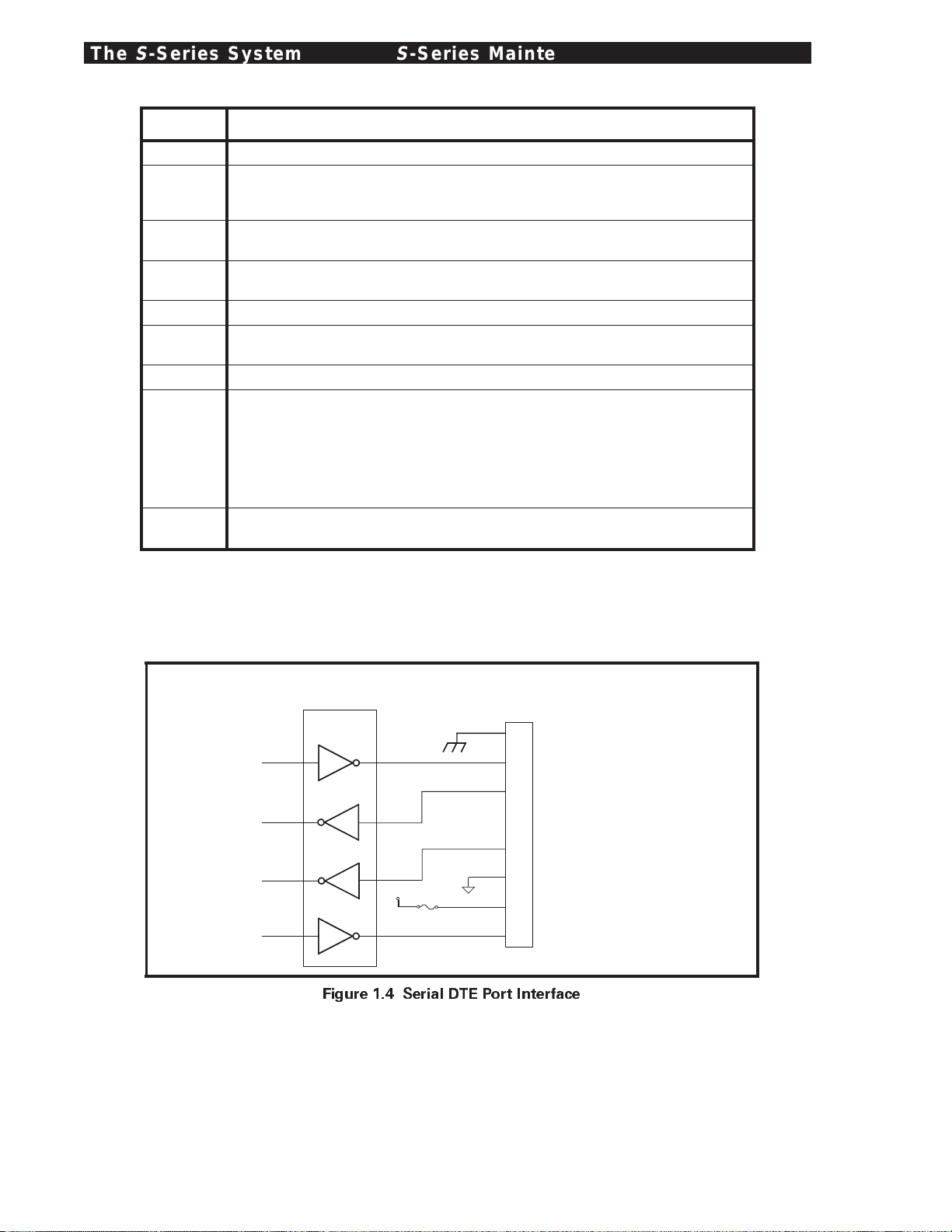
Pin No. Serial Data Port Signal Description
1 Frame Ground
2 Transmit Data: TXD is the serial data output of the Zebra S-Series printer.
It is on this lead that printer status information is transmitted
to the host.
3 Receive Data: RXD is the serial data input to the Zebra S-Series printer from
the host.
4 Request ToSend: RTS is an output from the Zebra S-Series printer.
It is a constantly active output to the host computer.
6 Data Set Ready: DSR is an input to the Zebra S-Series printer from the host.
7 Signal Ground: Tied to logic ground. This lead serves as the voltage
reference between the two communicating devices.
9 Reserved: For Future Use.
20 Data Terminal Ready: DTR is an output from the Zebra S-Series printer
and is the control line between the printer and the host. When the DTR
control line from the printer is in the ON condition, the host is allowed to
send data to the printer. When DTR is in the OFF condition, the host is not
allowed to send data. This condition occurs when the printer is configured
for DTR/DSR data flow control and the communication buffer is within
512 characters of its capacity.
5, 8, 10-19,
21-25
Unterminated: These leads are not used.
S
-Series Maintenance Manual: Volume 1
COMM PORT
MAX232
11
12
9
10
14
13
8
+5 V
7
4
F
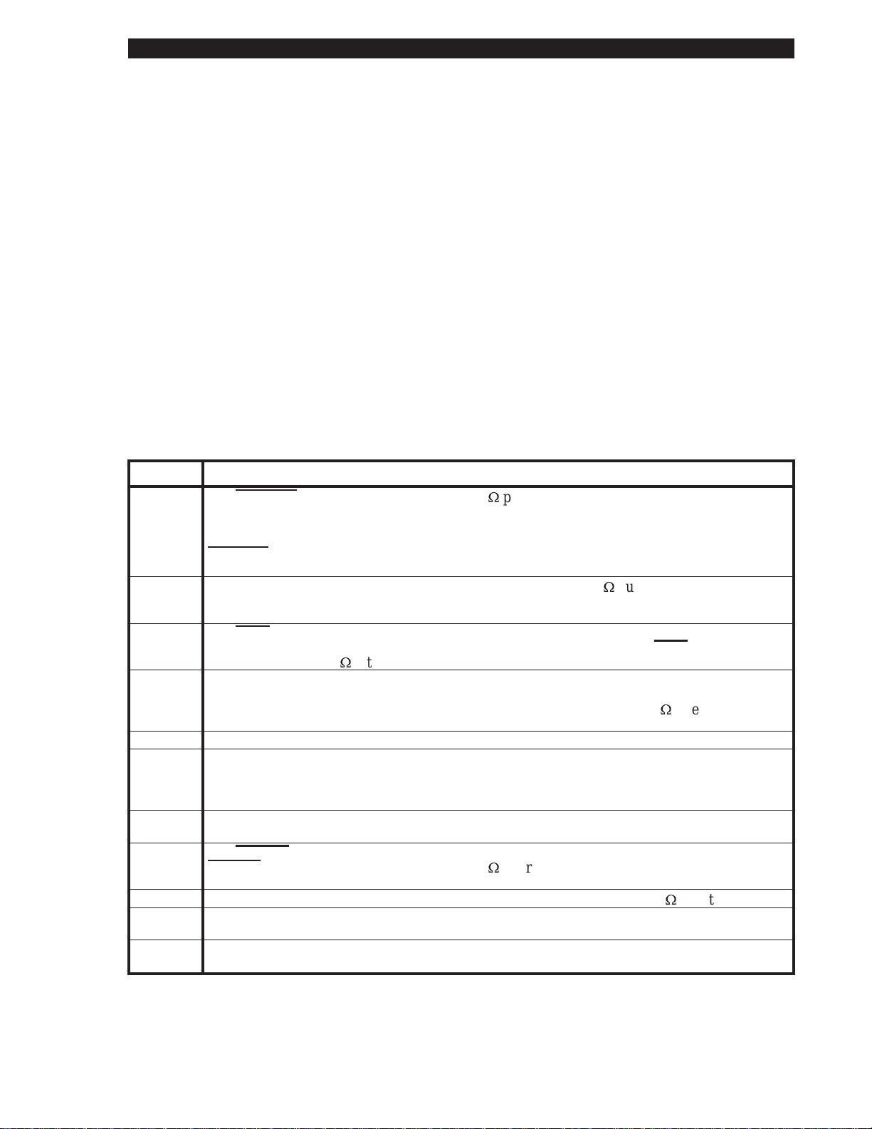
1 Amp
Figure 1.4 Serial DTE Port Interface
RS-232
J7
1
2
3
4
6
7
9
20
Frame Ground
RS-23 2
RS-23 2
Request To Send
Data Set Ready
Signal Ground
Reserved for
Future Use
Data Terminal
Ready
Transmit
Receive
Page 1-8 38452L Rev. 3
S
-SeriesMaintenanceManual:Volume1 TheS-Series System
Parallel Data Communications Overview
TheS-Seriesprintermayhaveaparalleldatacommunicationsportinsteadofthe
previouslymentionedserialdataport.TheParallelInterfacehasastandard
36-pinconnectorlocatedattherearoftheprinter.Inthisdatacommunica tion
method,thebitsofdatawhichmakeupeachcharacteraresentallatonetime
overseveralwiresinthecable,onebitperwire.
ParallelDataSignalLevels
ParalleldatasignalsaredefinedaseitherHIGHorLOW,whileControlSignals
areeitherActiveorInactive.ThedistinctionisduetothefactthatsomeControl
SignalsareactiveHIGHwhileothersareactiveLOW.Thevoltagelevelswhich
representtheseconditionsare:
DataSignal Voltage Level
HIGH +5VDC
LOW 00 VDC
ParallelInterfaceConnectorPinoutandDescription
Thefollowingchartprovidesadesc riptionofeachofthepinsintheparallel
connector.Astandardparalleldatacablewillprovidetherequired
interconnectionbetweenthehostandtheS-Seriesprinter.
Pin No. ParallelDataPort Signal Description
1 The
STROBEprinter input has internal3.3kÙpull-upresistorsto 5V (IOL=1.5mA) and is
designed to receive a signaldriven opencollector V
<=0.8V.This pin is a signalfromthe
OL
host computer.Its LOW goingedge willlatch the dataat theeight DATA inputs.Datais
non-transparentlylatched soas to avoid hold time requirementsonthe DATA signals. The
STROBEinput isdebounced torequirean activewidthgreaterthan 0.5µsecbefore datais
latched.
Ù
2-9 DATAinputshave TTL input characteristicswith internal3.3k
pullups andrepresent
1TTLunit load orless.The DATAinputs arepositivelogicwith a HIGHvoltagelevel
corresponding toa logic1.Pin 2throughPin 9= D0throughD7respectively.
10 The
ACKoutput is a 12microsecondactiveLOWpulse indicating thatthe printer is readyto
accept data. The active LOW state precedesBUSY by7 microseconds.
Ù
collector with a 3.3k
internalpull-up.The output sinks 7 mA to a VOL<=0.4V.
ACKis driven open
11 The BUSY output is active HIGHwheneverthe printercannotaccept datadueto any
normalorabnormal condition,includingBufferOverflow,Head Open,Over Temperature,
and Media Error conditions.BUSYis driven opencollector with a 3.3k
The output sinks 7mAto a V
OL
<=0.4V.
Ù
internalpull-up.
12 ThePAPEROUTsignalisactiveHIGHwhenevertheprinterisoutofmediaorribbon.
13 The SELECT signal function is determined byanadditional configuration option which
becomes active when the portispresent. Inthe default condition,SELECT is active HIGH
whenever theparallel portis powered upand the parallelportis enabled.Inthe non-default
condition, SELECT willgoactive LOW whenever the printeris printing.
18 +5VDC Supplyprovidesan output of +5VDCat a maximum currentrating of 50mA.
(InternalFuse Protected)
32 The
ERROROutput (Pin 15)is active LOW whenever anyerrorconditionis present.
ERRORis driven opencollector witha 3.0kÙinternalpull-up. The output sinks 7mAto a
<=0.4V.
V
OL
Ù
35 +5VDC Pull-Up provides an output of +5VDC throughan internal 3.0k
16,17,19-
SIGNALGROUNDSaretheLogicGroundsandReturnsforallInputandOutpu tsignals.
resistor.
30,33
14,15,31,
NOT USED-Theseleadsshouldbe left unconnected.
34,36
38452L Rev.3 Page1-9

TheS-Series System
S
-Series Maintenance Manual: Volume 1
R
Page 1-10 38452L Rev. 3

2 GettingReadytoPrint
Inthissection... Page
ControlsandIndicators..................................................................2-2
FrontPanelControls.................................................................2-2
FrontPanelLEDs......................................................................2-3
MediaLoading.................................................................................2-4
RibbonLoading...............................................................................2-6
MediaCalibration...........................................................................2-7
AdjustingthePrintDarkness........................................................2-7
AdjustingtheTear-OffPosition....................................................2-8
AdjustingthePositionoftheTopoftheLabel..........................2-9
AdjustingtheMediaSensorPositions.........................................2-9
UpperMediaSensor.................................................................2-9
LowerMediaSensor.................................................................2-11
OptionSwitches..............................................................................2-12
Bank1.........................................................................................2-13
Bank2.........................................................................................2-14
ThissectionofthemanualisintendedtosupplementtheUser’sGuideby
providingadditionalinformationtoaidtheservicetechnicianin
troubleshootingandmaintainingtheprinter.
38452L Rev.3 Page2-1
Getting Ready to Print
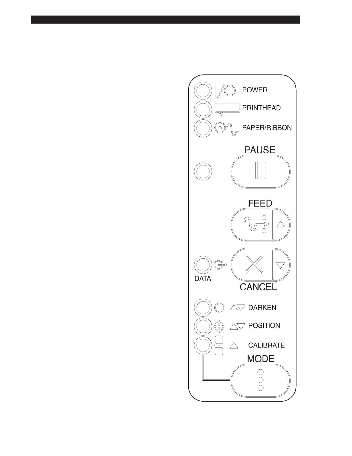
Controls and Indicators
All of the printer controls and indicators are located on the front of the unit except for the
Power ON/OFF Switch,whichis located at the rear of the printer.
Front Panel Controls
AC Power ON/OFF Switch
Controls appli cation of AC Power t o
the printer. When powered ON, the
printer will perform a Power ON Self
Test as it begins operation. Turning the
printer ON while holding down certain
front panel keys will cause additional
printer self tests to occur once the
Power ON Self Test is complete. The
AC Power Switch should be turned
OFF prior to connecting or
disconnecting any cables.
PAUSE Key
The PAUSE Ke y stops and restarts the
printing process. If the printer is idle
(not printing) when the PAUSE Key is
pressed, no printing can take place. If
the PAUSE Key is pressed while
printing is in progress, the printing
stops onc e the current label is
completed.
S
-Series Maintenance Manual: Volume 1
FEED Key
CANCEL Key
Pressing the PAUSE Key a second time
resumes the printing process.
The FEED Key forces the printer to
feed one blank label. If the printer is
idle (not pri nting) or if the PAUSE
function is active when the FEED Key
is pressed, one blank label feeds from
the pri nter immediately. If the printer
is printing, one blank label feeds out
after completion of the current batch of
labels. After one blank label is fed out,
pressing the FEED Key again will
provide a second blank label.
The CANCEL Key is only recognized
when the PAUSE function is active.
Press the CANCEL Key and the current
label format will be canceled. If no
format is printing, the next one to be
printed will be cancel ed. If there are no
formats in the printer, the CANCEL
Key is ignored. If the CANCEL Key is
pressed f or an extended period of time
(3 seconds), the printer will perform a
“Cancel All Formats” operation.
Figure 2.1 Front Panel Controls
Page 2-2 38452L Rev. 3
S
-SeriesMaintenanceManual:Volume1 GettingReadytoPrint
MODEKey
TheMODEKeycausestheprintertoentertheConfigurationMode.Inthis
Mode,thePrintDarkness,MediaTear-OffPosition,andLabelTopPosition
settingscanbeadjusted.
TheMediaCalibrationprocedureisalsoactivatedbytheMODEkey.
Refertotheuser’sguidefordetailsontheConfigurationModeandtheMedia
Calibrationprocedures.
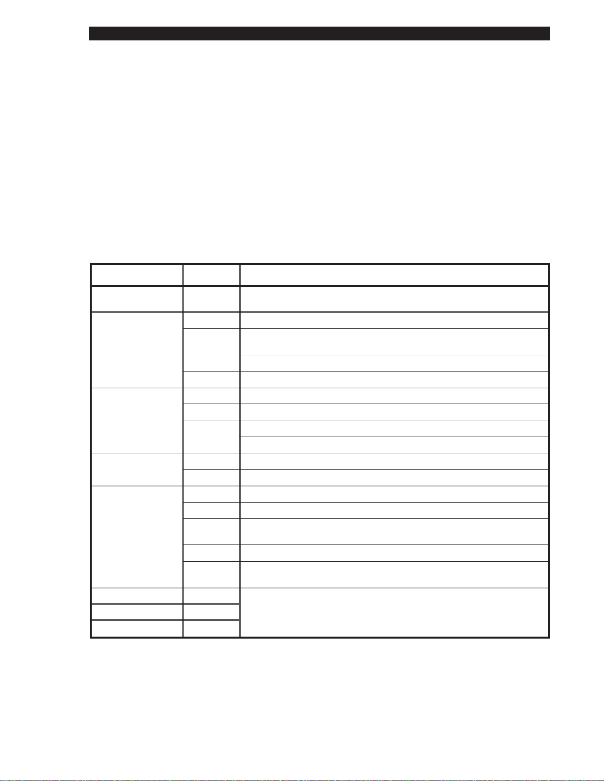
Front Panel LEDs
RefertoFigure2.1forthelocationoftheLEDs.
NOTE:IfanoperatingconditionwhichcausesanLEDtobeONconstantlyand
onewhichcausesthesameLEDtoflashoccuratthesametime,theLEDwill
flash.
LED Name Status Indication
POWER ON Printer isON.The AC Power ON/OFF Switch isintheONposition
and the powercord is connected.
PRINTHEAD OFF Normaloperation.
ON PrintheadOverTemperature condition.Printing stops untilthe
printheadcools down.Printingresumes automatically.
PrintheadUnderTemperature condition.Printingcontinues.
Flashing PrintheadOpen.
PAPER/
RIBBON
PAUSE OFF Normaloperation.
DATA OFF Idle, nodatabeing received.
DARKEN ON
POSITION ON
CALIBRATE ON
OFF Mediaandribbon (if used) are properlyloaded.
ON Paper out.
Flashing 1.InThermal TransferMode: Ribbon is out.
2.InDirectThermalMode: Ribbon is in the printer.
ON Printer has stopped allprintingoperations.
ON Labelsareprinting.
Single
flash
Flashing Receiving datafromhost computer.
Slow
flashing
TheCANCELkeywas pressed and a format was successfully
deleted fromthe print queue.
Printer senta “stoptransmitting data”(X-OFF)commandtothehost
computer.
Printer isintheConfiguration Mode.See theModeKeyoperation
for moreinformation.
38452L Rev.3 Page2-3

GettingReadytoPrint
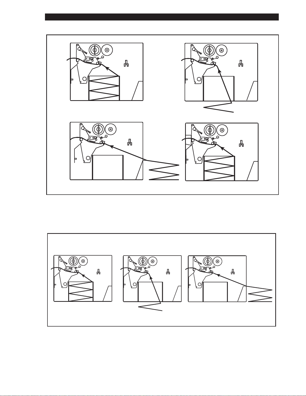
MediaLoading
S
-Series Maintenance Manual: Volume 1
TEAR-OFF
Figure2.2 RollMedia Loading
PEEL-OFF
105Se
TEAR-OFF PEEL-OFF
REWIND CUTTER
REWIND
160S
Figure 2.3 RollMedia LoadingDiagrams
Page2-4 38452L Rev.3
S
-SeriesMaintenanceManual:Volume1 GettingReadytoPrint
TEAR-OFF
REARSUPPLY
BOTTOMSUPPLY
CUTTER
INTERNALSUPPLY
105Se
Figure2.4 Fanfold MediaLoadingDiagrams
BOTTOMSUPPLY
Figure 2.5 FanfoldMedia LoadingDiagrams (160S)
REARSUPPLY
38452L Rev.3 Page2-5
GettingReadytoPrint
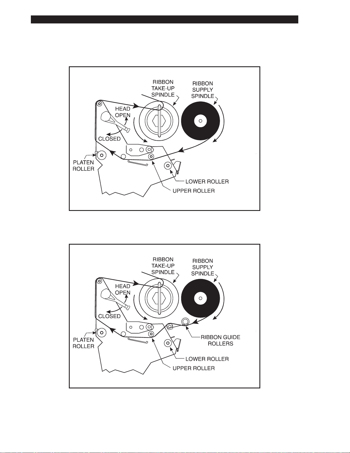
RibbonLoading
S
-Series Maintenance Manual: Volume 1
Figure 2.6 105Se RibbonLoadingDiagram
Figure 2.7160S RibbonLoadingDiagram
Page2-6 38452L Rev.3

S
-SeriesMaintenanceManual:Volume1 GettingReadytoPrint
MediaCalibration
IMPORTANT:Performthemediacalibrationprocedurew henmediais
firstinstalledorwhenadifferenttypeofmediaorribbonisinstalled.
Duringthisprocedure,theprinterautomaticallydeterminesthemediatype,label
length,mediaandribbonsensorsettings,andprintingmethod.
NOTE:Makesurethatthemediaandribbonrollsarepositionedagainstthe
innerspindlestops.
1. PresstheMODEkeythreetimes.ThePAUSEandCALIBRATElightsturn
on.
2. PressFEEDtocalibrate.Theprinterfeedssomemedia.TheMODElights
willflashonandofftoindicatethatthesettingshavebeensavedinmemory.
3. PressPAUSEtoexitPAUSEmode;thePAUSElightturnsoff.
AdjustingthePrintDarkness
Duetodifferencesintypesofmedia/ribbonandthewearontheprinthead,it
maybenecesarytoadjustthedarknesssetting(burntemperature)ofthe
S-Seriesprintheadtoachieveproperprinting.Usethefollowingprocedureto
adjustthedarkness;turningtheprinterOFFisnotrequiredforthenewsettingto
takeeffect.
CAUTION
Setthedarknesstothelowestpossibleforthedesiredprint
quality.Darknesssettoohighforagivenribbonmaycause
printheaddamage,inksmearing,ribbonwrin kle,and/orburning
throughoftheribbon.
1. Beginprintingabatchoflabels.Useaselftestlabel(seePrinter
Diagnostics)orpreferably,oneofyourownformats.
2. PausetheprintingbypressingthePAUSEkey.
3. PresstheMODEkeyoncetoplacetheprinterin“DarknessAdjustMode.”
TheDARKENlightturnson.
4. PresstheUPorDOWNkeytoadjustthecurrentsetting.
5. PressPAUSEtoressumeprinting;checkthenewsetting.
6. Repeatsteps2through5forfurtheradjustment.
7. Whendarknessiscorrect,pressPAUSEonceandMODEthreetimes.The
MODElightswillflashonandofftoindicatethatthesettingshavebeen
savedinmemory.
8. PressPAUSEtoresumeprinting.Monitorthenewsetting,adjustingif
necessary.
38452L Rev.3 Page2-7
TheS-Series System
Printing C onsiderations
S
-Series Maintenance Manual: Volume 1
Specification 105S/105
Resolution (thermal transfer
or direct thermal)
Dot size (square) 0.00492"
Maximum print width 4.09" (104 mm) 4.09" (104 mm) 4.09" (104 mm) 6.30" (160 mm)
Standard 512 KB
Maximum
print length
Bar code modulus (“X”) dimension 5 mil to 50 mil 6.6 mil to 66 mil 3.33 mil to 33.3 mil 5 mil to 50 mil
Programmable constant
printing speeds
Thin film printhead with Energy Control
memory
With 1 MG memory 39" (991 mm) 39" (991 mm) 18" (457 mm) 25" (635 mm)
203 dots per inch
(8 dots per mm)
(0.125 mm)
15" (381 mm) 26" (660 mm) N/A 9.5" (241mm)
2" (51 mm), 3" (76 mm), 4" (102 mm), 5" (127 mm), or 6" (152 mm) per second.
The 105S and 105Se with optional 300 dots/inch resolution support
2.4" (61 mm), 3" (76 mm), and 4" (102 mm) per second.
Optional
152 dots per inch
(6 dots per mm)
0.00656"
(0.167 mm)
Se
Optional
300 dots per inch
(12 dots per mm)
0.0033" x 0.0039"
(0.083 x 0.100 mm)
160
203 dots per inch
(8 dots per mm)
0.00492"
(0.125 mm)
Media Considerations
Media Specifications 105S/105
Se
160
S
S
Total media width Maximum 4.5" 114.3 mm 7.2" 182.9 mm
Minimum 0.75" 19.05 mm 2.0" 50.8 mm
Maximum 39" (991 mm) 25" (635 mm)
Tear-Off 0.63" 16.00 mm 0.63" 16.00 mm
Label length
Minimum
Peel-Off 0.50" 12.8 mm 0.50" 12.8 mm
Rewind 0.50" 12.8 mm 0.50" 12.8 mm
Cutter 1.25" 31.75 mm N/A N/A
Total thickness
(includes liner)
Maximum
position may need adjustment
if thickness is above 0.01")
(Printhead
0.012" 0.304 mm 0.012" 0.304 mm
Minimum 0.0023" 0.058 mm 0.0023" 0.058 mm
Core size 3.0" 76.2 mm 3.0" 76.2 mm
Maximum roll diameter 8.0" 203 mm 8.0" 203 mm
Interlabel gap
(0.115"/3 mm preferred)
Minimum mark length
Black mark
sensing
(thickness)
Minimum mark width
0.079" -
0.157"
2 mm - 4 mm 0.079" -
0.157"
2 mm - 4 mm
.118” 3 mm .118” 3 mm
.393” 10 mm .393” 10 mm
(extending in from the liner
or tag stock edge)
Maximum internal fanfold media
pack size (L x W x H)
8.0" x 4.5"
x 6.2"
203 x 114
x 158 mm
8.0" x 7.2"
x 6.2"
203 x 183
x 158 mm
Page 1-2 38452L Rev. 3
Getting Ready to Print
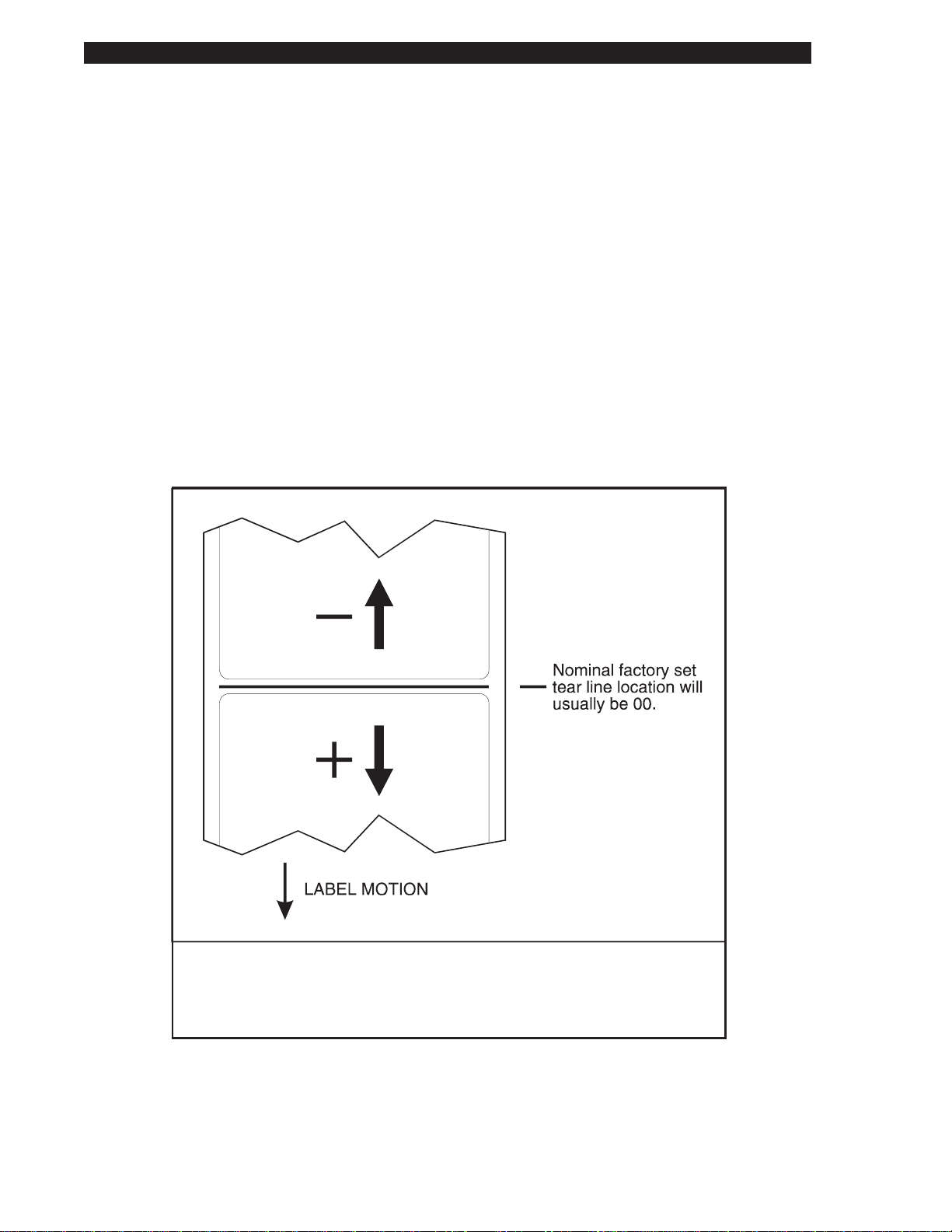
Adjusting the Tear-Off Position
This procedure sets the rest position of the media over the Tear Bar after
printing. The possible adjustment range is approximately plus or minus 80 dot
rows. Power need not be turned off to reset this parameter.
NOTE: The printer configura tion label reports the actual number of dot rows,
not the number of presses of the buttons used for adjustment.
1. Press the MODE key twice. The PAUSE and POSITION lights turn on.
2. Press the UP or DOWN key to adjust the current setting.
3. Press the MODE key twice. The MODE lights will flast on and off to
indicate that the settings have been saved in memory.
4. Press PAUSE to exit the PAUSE mode; the PAUSE light turns off.
S
-Series Maintenance Manual: Volume 1
This illustration shows how higher values move the label further out from
the printer (moves the tear line closer to the leading edge of the next label)
while lower values move the label into the printer (moves the tear line
closer to the edge of the printed label).
Figure 2.8 Tear-Off Position Adjustment
Page 2-8 38452L Rev. 3

S
-SeriesMaintenanceManual:Volume1 GettingReadytoPrint
AdjustingthePositionoftheTopoftheLabel
1. PresstheMODEkeytwice,thenpressandholdt heMODEkeyforabout
fiveseconds,untilthelightsc hange.PAUSE,D ARKEN,andCAL IBRATE
lightsturnon.
2. PresstheUPorDOWNkeytoadjustthecurrentsetting.
3. PresstheMODEkeytwice.TheMODElightswillflashonandoffto
indicatethatthesettingshavebeensavedinmemory.
4. PressPAUSEtoexitthePAUSEmode;thePAUSElightturnsoff.
AdjustingtheMediaSensorPositions
ThissensorisnotusedifBlackMarksens ingisselected.
NOTE:Ifyou’reusingcontinuousmedi a,donotperformt hisadjustment.
Leavethemediasensoratthefactory-setposition.
Non-continuousmediahasanotchoropeningbetweeneachlabel.Tomonitor
labelmovementyouneedtoalignthemediasensorwiththisnotchoropening.
Themediasensorconsistsoftwopartsthatmustbeproperlyalignedwiththe
notchoredgeofthelabel.Thefactory-setpositionshouldbesufficientformost
applications.Ifnot,performtheappropriateadjustments.
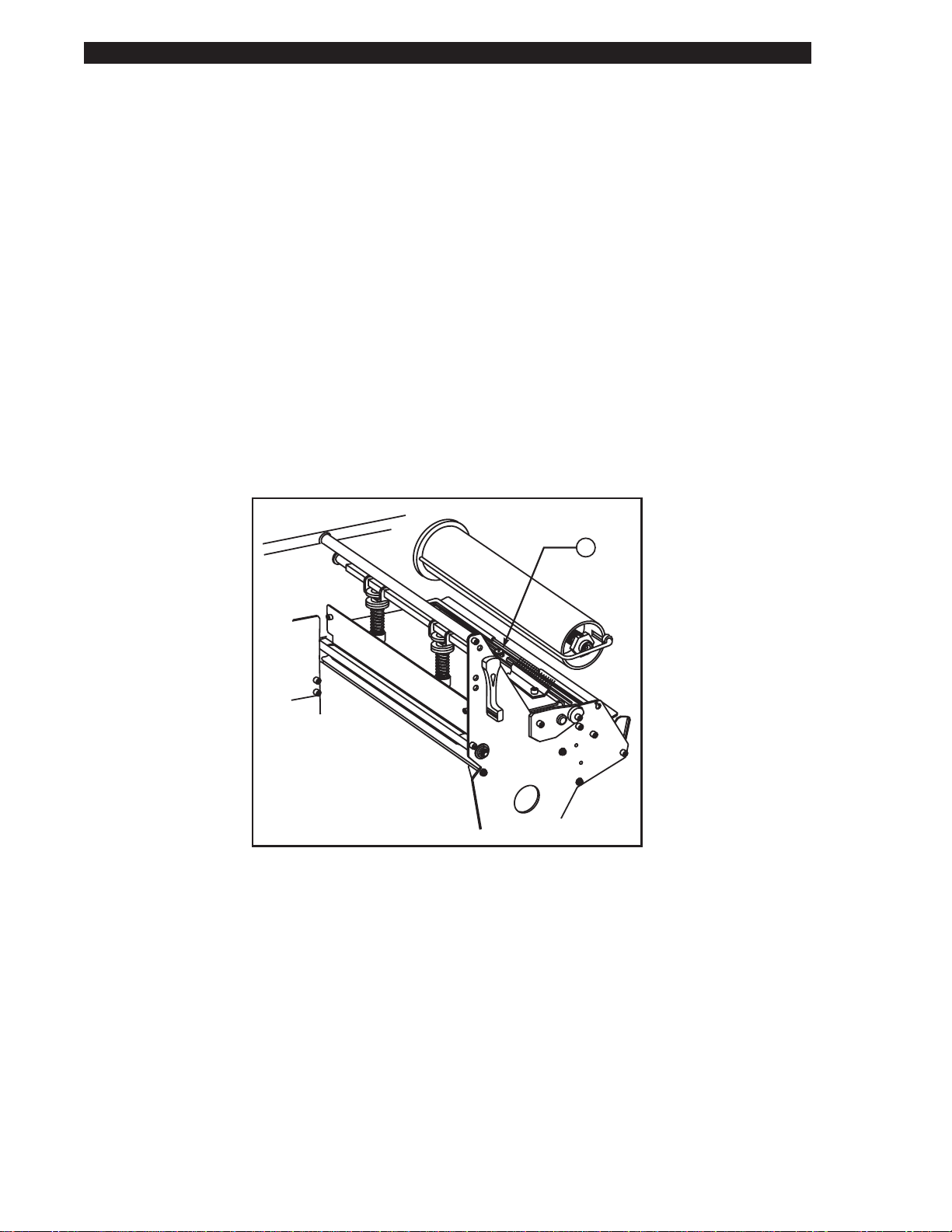
Adjusting the Upper Media Sensor
Toadjustfortheinsidehalfofthemedia:
1. Removetheribbon.Locatetheuppermediasensor(Figure2.9-A).
2. Loosen,butdonotremove,thePhillipsheadscrew.
3. Slidetheuppersensoralongtheslottoanypositionalongtheweb,except
wheretheroundedcornersofthelabelaredetected.Whenusingtagstock,
positiontheuppersensordirectlyovertheholeornotch.
4. Tightenthescrew.
38452L Rev.3 Page2-9
Getting Ready to Print
To adjust for the outside half of the media (160S ONLY):
1. R emove the ribbon. Locate the upper media sensor (Figure 2.9-A).
2. R emove the printer’s left side panel and reroute the media sensor cable to
provide a dditional slack.
3. R emove the Phillips head screw to release the upper section of the sensor
and wire cover.
4. Lift the upper media sensor assembly and move the sensor and the wire
cover to the outside half. Carefully pull the wires through the tie wrap.
You may need to set aside the sensor wire cover if the adj ustment is far to
the outside.
5. Replace and tighten the Phillips head screw.
6. Make sure the wires are routed back into the g roove of the media sensor
bracket.
7. Replace the printer ’s left side panel.
S
-Series Maintenance Manual: Volume 1
Figure 2.9 Upper Media Sensor
A
Page 2-10 38452L Rev. 3
S
-Series Maintenance Manual: Volume 1 Getting Ready to Print
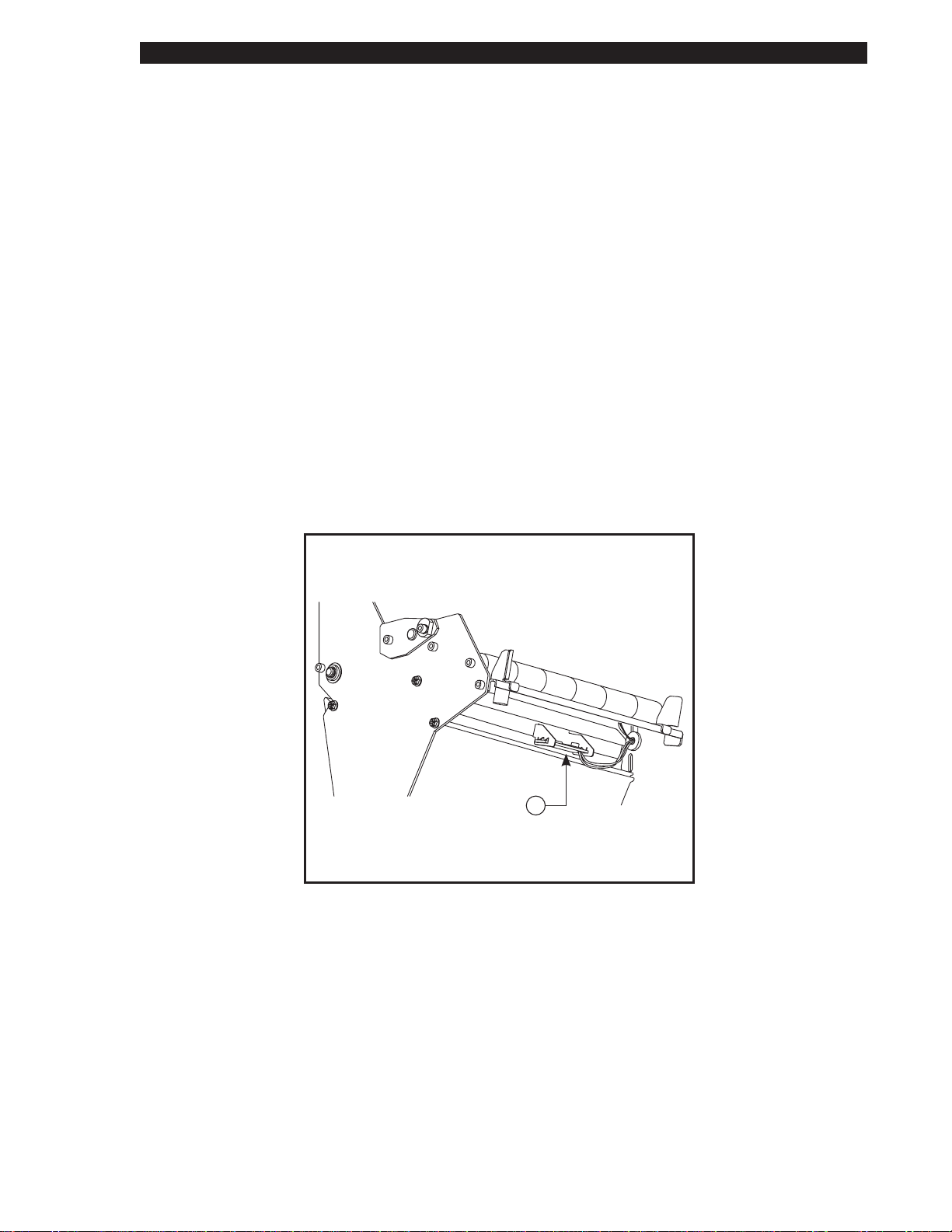
Lower Media Sensor Adjustment
1. Locate the lower media sensor assembly under the rear idler roller
(Figure 2.10-A). (It is a spring clip holding a circuit boa rd.)
2. Slide the sensor until the two brass-colored infrared emitters are under the
upper medi a sensor. Gently pull wires out as needed (wires should have a
little slack).
3. NOTE: If the sensor is being moved inward and a large loop of wire
develops, remove the cover from the electronics side of the printer and
gently pull the wires through. Clamp the wires so that they do not rub any
belts.
A
Figure 2.10 Lower Media Sensor
38452L Rev. 3 Page 2-11

Getting Ready to Print
Option Switches
These switches are located above the signal interface cable connector. See
Figure 2.11.
In the following tables, “R” means the switch is in the right position, while “L”
means the switch is in the left position. Refer to Figure 2.12.
S
-Series Maintenance Manual: Volume 1
BANK 2BANK 2
BANK 1
(ONLY ON
SERIAL UNITS)
SIGNAL INTERFACE
CABLE CONNECTION
105 and 160
Se S
PARALLEL
Figure 2.11 Option Switch Locations
105 and 160
Se S
SERIAL
(L)(R)
1 2 3 4 5 6 7 8
Figure 2.12 Option Switches
Page 2-12 38452L Rev. 3

S
-Series Maintenance Manual: Volume 1 Getting Ready to Print
Bank 1 (Serial interface printers only)
NOTE: Parallel interf ace printers do not have Bank 1 switches since they are
not required. Bank 1 switches must be properly positioned to establish serial
data communications with the host computer. Once communications are
established, do not change the position of th ese switches.
Bank 1
Switch
321
R R R 9600
R R L 19200
R L R 110
R L L 300
L R R 600
L R L 1200
L L R 2400
L L L 4800
Switch
4
R7
L8
Switch
6 5 Parity
R R Even parity
R L Parity disabled
L R Odd parity
L L Parity disabled
Switch
7 Communication Handshake Control
R XON/XOFF control
L DTR/DSR control
Switch
8 Error Detection Protocol
R No error detection
L Error detection active
(Must be set to 8 data bits for Code Page 850)
Baud Rate
Data Bits
38452L Rev. 3 Page 2-13

Getting Ready to Print
Bank 2
These switches can manually override any ZPL commands that affect print
mode, media mode, and media type. They can also override settings established
during the calibration procedure.
If you do not want to override ZPL or the calibration settings, disable one or
more of the options by setting switches 1, 4, and/or 7 to t he “R” position and
turn the power on. With these disabled, the printer will requi re ZPL commands
to set print mode, media mode, and/or media type.
To override, set the switches to one of the modes shown in the table. If you a re
in the process of printing, this change takes affect on the next label printed. If
you change the switches from active to disabled after printer power-up, the
printer remains in the current mode until a ZPL command changes the mode.
Switch
321
R R L Cutter
R L L Tear Off
L R L Peel Off
L L L Rewind
- - R Disabled
Switch
6 5 4 Media Mode
R R L Non-continuous mark sense
R L L Non-continuous web sense
L L L Continuous
- - R Disabled
Switch
8 7 Media Type
R L Thermal transfer
L L Direct thermal
- - R Disabled
S
-Series Maintenance Manual: Volume 1
Bank 2
Print Mode
Page 2-14 38452L Rev. 3

3 PrinterDiagnostics
Inthissection... Page
PowerONSelfTest........................................................................3-1
PrinterSelfTests.............................................................................3-1
CANCELKeySelfTest...........................................................3-3
PAUSEKeySelfTest...............................................................3-4
FEEDKeySelfTest..................................................................3-5
MODEKeySelfTest................................................................3-6
FEED,PAUSEandCANCELKeys.......................................3-6
PAUSEKeyandCANCELKey..............................................3-7
FEEDKeyandCANCELKey................................................3-7
FEEDKeyandPAUSEKey....................................................3-7
ExtendedPrinterDiagnostics........................................................3-9
PAUSEKeyLoopbackTest.....................................................3-9
FEEDKeyLoopbackTest.......................................................3-10
BuiltintotheZebraS-SeriesPrintersa retestroutinestoaidthetechnicianin
diagnosingfaults.
Power ONSelfTest
APowerONSelfTest(POST)isperformedeachtimetheprinteristurnedON.
Thistestchecksforproperinitializationofvariouselectroniccircuitsand
establishesstartingparametersasthosestoredintheprinter’smemory.During
thistestsequence,thefrontpanelLEDswillturnONandOFFtoinsureproper
operation.
Attheendofthisselftest,onlythePOWERLEDwillremainlit.IfotherLEDs
remainlit,refertoTroubleshootinginthismanual.
PrinterSelf Tests
Theseselftestsproducesamplelabelsandprovidespecificinformationwhich
helpsdeterminetheoperatingconditionsfortheprinter.
Eachselftestisenabledwhenafr ontpanelkeyispressedwhilethepri nter’s
ACPowerSwitchisturnedON.KeepthekeypresseduntilthefrontpanelLEDs
turnON.
WhenthePowerOnSelfTestiscompleted,theselectedprinterselftestwill
startautomatically.
38452L Rev.3 Page3-1

Printer Diagnostics
NOTES: It is r ecommended that full width media be used when performing
these t ests. Labels less than full w idth in size will lose printing on the right side.
Label length will determine the amount of pr inting starting at the top of th e label.
When performi ng these self tests while in the Peel-Off Mode, the operator must
remove t he labels as they become available.
When canceling a self test prior to its actual completion, always turn the printer
power O FF and then back ON to reset the printer.
Some of the printer self tests produce labels at varying print speeds. These
speeds may be referred to as “inches per second,” “millimeters per second,” or
by alphabetic letter designation (i.e., “A,” “B,” “C,” etc.). The following chart
shows the relationships between the different speeds.
S
-Series Maintenance Manual: Volume 1
Letter
Designation
A* 2" 51 mm
B3"76mm
C 4" 102 mm
D 6" 152 mm
* S peed “A” for the 105S and 105Se with the optional 300 dots-per-inch
printhead is 2.4" (61 mm).
Inches
per Second
5" 127 mm
Millimeters
per Second
Page 3-2 38452L Rev. 3

S
-SeriesMaintenanceManual:Volume1 PrinterDiagnostics
CANCEL Key Self Test
Thisselftestprintsasinglelabelwhichcontainsalistingoftheprinter’scurrent
configurationparametersstoredinConfiguration(EEPROM)Memory.Pressthe
CANCELKeywhileturningtheACPowerSwitchON.Asamplelabelisshown
inFigure3.1.
Theprinterconfigurationmaybechangedtemporarilyforspecificlabelformats
orribbonandlabelstock,orpermanentlybysavingthenewparametersin
EEPROMMemory.Savingnewparametersoccurswheneveraprinter
configurationprocedureisperformed.RefertoGettingReadytoPrintfor
furtherdetailsonthePrinterConfigurationprocedure.
Figure 3.1 CANCELKey Self Test Label
38452L Rev.3 Page3-3

PrinterDiagnostics
PAUSE Key Self Test
EnterthisselftestmodebypressingthePAUSEKeywhileturningtheAC
powerON.
Thisselftestconsistsofeightseparatetestsequences,printinglabelsatboth
Speed“A”andSpeed“D”(“C”forthe300-dpi105Sand105Se).Duringthe
firstfourtestsequences,theprintersimulatesthe“Tear-Off”modeand
backfeedsthemediapriortoprintingeachlabel.Duringthelastfourtest
sequences,theprintersimulatesthe“Rewind”modeanddoesnotbackfeedthe
media.
Thisselftestcanbeusedtoprintthetestlabelsrequiredwhenmaking
adjustmentstotheprinter’smechanicalassemblies.Thesetestlabelscanalso
beprintedwhenrequiredduringtheConfigurationandCalibrationprocesses
describedinGettingReadytoPrint.SeethelabelexampleinFigure3.2.
NOTE:IftheTakeLabelSensorpairismountedonthefrontoftheprinter,
“PEELOPTIONINSTALLED”willbeprintedonthefirstlabel.Duringthefirst
fourtestsequences,eachlabelmustbemanuallyremovedfromthesensorpath
beforethenextlabelwillprint.Duringtestsequencesfivethrougheight,the
TakeLabelSensorpairisnotenabledandcontinuousprintingoccurs.
S
-Series Maintenance Manual: Volume 1
Tobypassthefirstfoursequences,pressthePAUSEKey;thentearoffthefirst
printedlabel.Oncethelabelisremoved,theprinterwillenterthePAUSEmode.
PresstheCANCELKeyfourtimesandmakesuretheDataLEDflashesonce
eachtime.PressthePAUSEKeyoncetostarttestsequencefive.
1. Theinitialtestsequenceprints15labelsatspeed“A”thenautomatically
PAUSEStheprinter.Another15la belsequencewillstartifthePA USEKey
ispressedtopermitprinting .
2. WhiletheprinterisPAUSED,presstheCANCELKeyoncetoselectthe
secondselftestsequence.NoweachtimethePAUSEKeyispressed,the
printerprints15labelsatspeed“D”(“C”forthe300-dpi105Sand105Se).
Another15labelsequencewillstartifthePAUSEKeyispressedtopermit
printing.
3. WhiletheprinterisPAUSED,presstheCANCELKeyoncetoselectthe
thirdselftestsequence.NoweachtimethePAUSEKeyispressed,the
printerprints50labelsatspeed“A”.Another50labelsequencewillstartif
thePAUSEKeyispressedtopermitprinting.
4. WhiletheprinterisPAUSED,presstheCANCELKeyoncetoselectthe
fourthselftestsequence.NoweachtimethePAUSEKeyispressed,the
printerprints50labelsatspeed“D”(“C”forthe300-dpi105Sand105Se).
Another50labelsequencewillstartifthePAUSEKeyispressedtopermit
printing.
5. SelfTestsequencesfivethrougheightarethesameassequencesone
throughfourbutsimulatethe“Rewind”modeofoperationbynot
backfeedingatthebeginningofeachlabel.Inaddition,theTakeLabel
Sensorpairisdisabledduringthesetestsequencessolabelsdonotneedto
beremovedindividually.
Page3-4 38452L Rev.3

S
-Series Maintenance Manual: Volume 1 Printer Diagnostics
Figure 3.2 PAUSE Key Self Test Label
FEED Key Self Test
The CANCEL Key Self Test should be performed prior to this Self Test.
Information on the printed “Configuration” Label (CANCEL Key Self Test) will
be used with the results of this self test to determine the best Darkness Setting
for a specific media/ribbon combination.
The FEED Key Self Test Label will print out at various PLUS or MINUS
darkness settings relative to the darkness value shown on the configuration
label. Inspect these labels and determine which one has the best darkness setting
for t he application. See the example in Figure 3.3.
Figure 3.3 FEED Key Self Test Label
38452L Rev. 3 Page 3-5

PrinterDiagnostics
Thevalueprintedonthatlabelisaddedto(plus)orsubtractedfrom(minus)the
“Darkness”valuespecifiedontheConfigurationLabel.
Theresultingnumericvalue(0to30)ist hebestdarknessvalueforthatspec ific
media/ribboncombination.
ThevalueselectedcanbeenteredwhileperformingaMediaDarkness
Adjustment.ThePLUSvaluecanbeenteredbypressingtheUP(FEED)Key,
whiletheMINUSvalueisenteredbypressingtheDOWN(CANCEL)Keythe
appropriatenumberoftimes.RefertotheCalibrationprocessesdescribedin
GettingReadytoPrint.
Optionally,therequiredrelativedarknessvaluecanbeprogrammedintothe
ZPLIIlabelformatssenttotheprinter.
MODE Key Self Test
ThisselftestplacestheprinterintheCommunicationsDiagnosticsMode.
PresstheMODEKeywhileturningtheACpowerswitchON,thensendalabel
formattotheprinter.Inthismode,theprinterprintstheASCIIcharactersand
theircorrespondinghexadecimalvaluesforanydatareceivedfromthehost
computer.SeetheexampleinFigure3.4.
S
-Series Maintenance Manual: Volume 1
NOTE:Turntheprinter’spowerOFFtoexitthisselftest.
Figure3.4MODEKeySelfTestLabel
FEED, PAUSE, and CANCEL Keys
Ifthesethreekeysarehelddepressedatthesametimeandthepoweristurned
ON,theprinterwillentertheMediaSensorandR ibbonSensorSensi tivity
AdjustmentMode.SeeCorrectiveMaintenancefortheseadjustments.
Page3-6 38452L Rev.3

S
-SeriesMaintenanceManual:Volume1 PrinterDiagnostics
PAUSE Key and CANCEL Key
Thisselftestcanbeusedtoverifyproperprinteroperationafterpartshavebeen
replacedoradjusted.Whenactivated,theprinterprintsamaximumof500Head
TestLabels.Eachlabelbackfeedspriortoprintingandfeedsforwardtotherest
positionafterprinting.Aserializednumberwillprintoneachlabel.Pressthe
PAUSEKeyorturntheprinterp owerOFFtostopprint ing.RefertoFigure3 .6.
FEED Key and CANCEL Key
Thisselftestisnormallyperformedduringthemanufacturingprocessoraftera
majoroverhaulofthemechanicalassemblies.Thistestprintsseven
pre-programmedlabelformats,firstatSpeed“D,”thenthesameformatsat
Speed“A.”Theprinterwillautomaticallypauseaftereachformat.Thesequence
oflabelformatsisshownbelow.RefertoFigures3.7through3.13.
FORMAT PRINTING TEST FUNCTION
1 20atSpeed D LeftRibbonWrinkle Test
2 20atSpeed D RightRibbon WrinkleTest
3 20atSpeed D Bar CodeWrinkleTest(Code-39)
4 20atSpeed A LeftRibbonWrinkle Test
5 20atSpeed A RightRibbon WrinkleTest
6 20atSpeed A Bar CodeWrinkleTest(Code-39)
7 10atSpeed D UsableArea Test
8 10atSpeed D Head TemperatureTest
9 10atSpeed D UpperSmear Test
10 10atSpeed D Lower SmearTest
11 10atSpeed A UsableArea Test
12 10atSpeed A Head TemperatureTest
13 10atSpeed A UpperSmear Test
14 10atSpeed A Lower SmearTest
FEED Key and PAUSE Key
Pressingthesetwokeysatthesametime,whileturningthepowerON,
temporarilyresetstheprinterconfigurationtothefactorydefaultvalues.These
valueswillbeactiveuntilpoweristurnedOFF.Ifthefactorydefaultconditions
aretobeusedonapermanentbasis,savethembypressingtheMODEKeyfour
times-MODELEDscycleONthenOFF.AMediaCalibrationprocedure
mustbeperformedafterfactorydefaultvalu esaresaved.Figure3.5
indicateswhichprinterfunctioncontrolseachoftheconfigurationparameters.
38452L Rev.3 Page3-7

Printer Diagnostics
Parameter Controlled By
Darkness Front Panel Adjustment or ZPL II
Tear Off Adjust Front Panel Adjustment
Web Sensor Front Panel Calibrate or ZPL II
Media Sensor Front Panel Calibrate or ZPL II
Ribbon Sensor Front Panel Calibrate or ZPL II
Mark Media Sensor DIP Switches or ZPL II
Mark Sensor Front Panel Calibrate or ZPL II
Media LED Front Panel Calibrate or ZPL II
Ribbon LED Front Panel Calibrate or ZPL II
Mark LED Front Panel Calibrate or ZPL II
Label Length Front Panel Calibrate or ZPL II
Max Label Length ZPL II Controlled
Print Width ZPL II Controlled
Print Mode DIP Switches or ZPL II Controlled
Media Type Front Panel Calibrate, DIP Switches or ZPL II
Print Method Front Panel Calibrate, DIP Switches or ZPL II
Host Port Firmware Controlled
Network Port Firmware Controlled
Baud DIP Switches
Data Bits DIP Switches
Parity DIP Switches
Stop Bits Firmware Controlled
Handshake Dip Switches
Protocol Dip Switches
Delimiter ZPL II Controlled
Format Prefix ZPL II Controlled
Control Prefix ZPL II Controlled
Network ID ZPL II Controlled
Modes Enabled ZPL II Controlled
Modes Disabled ZPL II Controlled
Resolution ZPL II Controlled
Backfeed ZPL II Controlled
Label Top Front Panel Calibrate or ZPL II
Left Position ZPL II Controlled
Socket 1 ID EPROM
Socket 2 ID EPROM
Firmware Firmware Controlled
Configuration Firmware Controlled
Memory Functioning Memory
B: Memory Firmware Controlled
Media Power Up ZPL II Controlled
Media Head Close ZPL II Controlled
S
-Series Maintenance Manual: Volume 1
Figure 3.5 Configuration Parameter Controls
Page 3-8 38452L Rev. 3

S
-Series Maintenance Manual: Volume 1 Printer Diagnostics
Extended Printer Diagnostics
Additional diagnostic tests are available for printhead assembly adjustments.
These diagnost ics tests are only accessible when the data interface cable is
disconnected fr om the printer and a Loopback Connector i s attached in its place.
The Serial Loopback Connector is a 25-pin “D” type (DB25P-Male ) style with
the following pins tied together.
• pins 2 and 3
• pins 6 and 20
• pins 13 and 14
• pins 16 and 19
The Par allel Loopback Connector is a standard 36-pin parallel connector
mounted to a small circuit board. This connector is available from Zebra
Technologies as Part # 44680.
For each of these diagnostic tests, the printer will “transmit” the test label
format out of the Data Interface Connector to the Loopback Connector. The
Loopback C onnector passes the test label format back to the printer as “receive”
Data and the test label is printed.
PAUSE Key Loopback Test
This test demonstrates the media movement capabilities of the printer and
provides a t est label to view while making print quality adjustments.
With the Loopback Connector in place, press the PAUSE Key while turning the
AC Power Switch ON.
After the Power On Self Test, the printer will print 500 Head Test label s. Each
label will backfeed prior to printing and feed to the rest position after printing.
A s erialized number will print on each label for label comparison purposes if
required. See the example in Figure 3.6.
The PAUSE Key can be used to stop and restart the printing operation.
Figure 3.6 PAUSE Key Loopback Test Label
38452L Rev. 3 Page 3-9

Printer Diagnostics
FEED Key Loopback Test
With the Loopback Connector in place, press the F EED Key while turning the
AC Power Switch ON.
After the POST, the printer will begin printing a series of label formats as shown
in the chart below. The printer will PAUSE at the end of each printed format.
Press the PAUSE Key to begin printing the next format. R efer to the label
examples in Figures 3.7 through 3.13.
The PAUSE Key can be used to stop and restart the printing operation. When the
printer is p aused, the CANCEL Key can be used to move to the next label format.
FORMAT PRINTING TEST FUNCTION
1 20 at Speed D* Left Ribbon Wrinkle Test
2 20 at Speed D* Right Ribbon Wrinkle Test
3 20 at Speed D* Bar Code Wrinkle Test (Code-39)
4 20 at Speed A Left Ribbon Wrinkle Test
5 20 at Speed A Right Ribbon Wrinkle Test
6 20 at Speed A Bar Code Wrinkle Test (Code-39)
7 10 at Speed D* Usable Area Test
8 10 at Speed D* Head Temp Test
9 10 at Speed D* Upper Smear Test
10 10 at Speed D* Lower Smear Test
11 10 at Speed A Usable Area Test
12 10 at Speed A Head Temp Test
13 10 at Speed A Upper Smear Test
14 10 at Speed A Lower Smear Test
S
-Series Maintenance Manual: Volume 1
* “C ” for the 105S and 105Se with the 300 dots/inch printhead
Figure 3.7 Format 1 (8) Test Label
Page 3-10 38452L Rev. 3

S
-Series Maintenance Manual: Volume 1 Printer Diagnostics
Figure 3.8 Format 2 (9) Test Label
Figure 3.9 Format 3 (10) Test Label
Figure 3.10 Format 4 (11) Test Label
38452L Rev. 3 Page 3-11

Printer Diagnostics
S
-Series Maintenance Manual: Volume 1
Figure 3.11 Format 5 (12) Test Label
Figure 3.12 Format 6 (13) Test Label
Figure 3.13 Format 7 (14) Test Label
Page 3-12 38452L Rev. 3

4 PreventiveMaintenance
Inthissection... Page
FieldMaintenanceFunctions........................................................4-1
ToolsRequired.................................................................................4-1
CleaningtheS-SeriesPrinter........................................................4-1
CleaningthePrinthead...................................................................4-2
CleaningtheSnapPlate.................................................................4-2
CleaningtheCutterModule..........................................................4-4
LubricatingtheCutterModule......................................................4-4
RecommendedPreventiveMaintenanceSchedule.....................4-5
FieldMaintenanceFunctions
FieldmaintenancefunctionsfortheZebraS-Seriesprintercanbedivide dinto
twobasiccategories.
• Thissectionofthemanualcontainspreventivemaintenanceproceduresand
operatorcareinstructions.Preventivemaintenanceconsistsofavisual
inspectionandgeneralcleaningoftheinteriorandexterioroftheunitand
printhead.Theseproceduresmaybeperformedbytheoperatorandshould
beperformedonaregularbasis.
• Correctivemaintenance,describedinCorrectiveMaintenance,provides
detailedstepsforresolvingfaults.Repairsareaccomplishedbyreplacement
ofcomponentsormodulesorbyadjustments.
ToolsRequired
Toproperlyperformthepreventivemaintenancetasks,theservicetechnician
shouldbeequippedwiththefoll owing:
• Applicators
• 70%isopropylalcohol
• Citrus-basedcleaner
Unlessindicatedotherwise,turnpowerOFFbefore
performingmaintenanceprocedures.
CleaningtheS-SeriesPrinter
EXTERIOR—TheexteriorsurfacesoftheS-Seriesprintermaybecl eaned
withalint-freecloth.DONOTusesolventsorharshcleaningagents.Iftheunit
isexcessivelydirty,amilddetergentsolutionordesktopcleanermaybeused
sparingly.
WARNING
38452L Rev.3 Page4-1

PreventiveMaintenance
INTERIOR—Asrequired,removeanydirt/lintaccumulatedintheinteriorof
theprinterusingasoftbristlebrushand/orvacuumcleaner.Itisagoodpractice
toinspecttheseareasaftereveryfourthrollofmedia.
CleaningthePrinthead
Inconsistentprintqualitysuchasblankareasinthebarcodesorgraphicsmay
indicateadirtyprinthead.Foroptimumperformance,theprintheadshouldbe
cleanedregularly.Whenprintingindirectthermalmode,performthefollowing
cleaningprocedureaftereveryrollofmedia(or500feetoffanfoldmedia).
Whenprintinginthethermaltransfermode,cleanaftereveryrollofribbon.
NOTE:ItisnotnecessarytoturntheprinterOFFpriortocleaning.Alllabel
formats,images,andparametersettingsstoredintheprinter’smemorywillbe
lostiftheprinteristurnedOFF.IftheprinteristurnedOFF,itmaybenecessary
toreloadsomeitemsintotheprinter’smemory.
1. OpentheprintheadbymovingtheLatchingLevertotheOPENposition.
2. Removethemediaandribbon(ifpresent).
3. Useanapplicatormoistenedwith70%isopropylalcoholtowipetheprint
elementsfromendtoend.(RefertoFigure4.1.Theprintelementsarethe
brownstripjustbehindthechromestrip.)Allowafewsecondsforthe
solventtoevaporate.
4. RotatethePlatenRollerandcleanthoroughlywithisopropylalcohol.
5. Brushorvacuumanyaccumulatedpaperlintanddustawayfromtherollers
andtheMediaandRibbonSensors.
6. Reloadribbonand/ormedia,closeandlatchtheprinthead,andcontinue
printing.
S
-Series Maintenance Manual: Volume 1
CleaningtheSnapPlate
Intheeventofalabeljam,theMediaGuidePlate(SnapPlate)canberemoved
andcleaned.RefertoFigure4.2andfollowthesesteps.
1. OpenthePrintheadtoitsfullyopenpositionbyrotatingtheLatchingLever
counterclockwise.ThePrintheadpivotstoanalmostverticalposition.
2. Fromthefrontoftheprinter,po pupthefrontedgeo ftheSnapPlateusing
yourfingernailoraflat-bladescrewdriver.
3. LiftthefrontedgeoftheSnapPlatewhilepullingitupandoutoftheprint
mechanism.
4. CleantheSnapPlate,includingtheraisedareadirectlybelowtheribbon
sensor.Removeanystucklabelsanduseacitrus-basedcleanertoremove
anybuilt-upadhesive.
IncorrectinstallationoftheSnapPlatecandisablethe
5. ReplacetheSnapPlatebyplacingthebacklegsintheopeningsintheMain
MediaGuidewhileslidingittotherearoftheopeningsandsnappingit
downintoplace.RefertoFigure4.2.
CAUTION
RibbonSensororcauseheadpressureimbalance.
Page4-2 38452L Rev.3

S
-SeriesMaintenanceManual:Volume1 PreventiveMaintenance
PRINTHEAD
RIBBON
SENSOR
LABEL
AVAILABLE
SENSORS
PLATEN
ROLLER
Figure4.1PrintheadCleaning
PEEL/TEAR
BAR
SNAP
PLATE
Figure4.2SnapPlateCleaning
38452L Rev.3 Page4-3

Preventive Maintenance
Cleaning the Cutter Module
Periodically, the Cutter Module should be cleaned to remove paper dust and
label residue. Refer to Figure 4.3.
Clean the stationary cutter blade with a cotton swab moistened with a
citrus-based cleaner when it becomes gummed up with label adhesive or paper
debris. After cleaning, apply a small amount of petroleum lubricating grease to
the moving cutter parts.
S
-Series Maintenance Manual: Volume 1
Figure 4.3 Cutter Blade Cleaning
Lubricating the Cutter Module
Certain applications or types of label stock may cause the cutter blades to
eventually st art to squeak. This commonly occurs when less-than-full width
media is being used.
To eli minate the squeak and prolong cutter life, first turn off the printer. Next,
clean the lower cutter blade by following the above procedure. Then, coat a
cotton swab with a small amount of petroleum lubricating grease and wipe the
swab along the top of the lower cutter blade and on the surface of the ring at the
end of the rotary blade (refer to Figure 4.4).
DETAIL
Figure 4.4 Cutter Module Lubrication
Page 4-4 38452L Rev. 3

S
-SeriesMaintenanceManual:Volume1 PreventiveMaintenance
RecommendedPreventiveMaintenanceSchedule
AREA METHOD INTERVAL
PRINTHEAD Isopropyl alcohol When printinginthedirect
PLATEN ROLLER Isopropyl alcohol
MEDIASENSOR Airblow
MEDIA PATH Isopropyl alcoholandcloth
RIBBON SENSOR Airblow
PEELROLLER Isopropyl alcohol Once per month
LABELAVAILABLE
SENSOR
RIBBONFEEDING PATH Visual Once per three months
DRIVE BELTS Visual Six monthsor500rolls
CUTTER BLADES Citrus-based cleanerand/or air
Formalpreventivemaintenance is not required onthese
spindles. Spindletension should notbe adjustedunless
the printer ismalfunctioning(i.e.,spindlesnot rotating
MEDIA TAKE UPSPINDLE
smoothly).Therecommendedtensionsandadjustment
procedures are provided inCorrectiveMaintenance.
Airblow Once per six months
blow
thermalmode:after everyroll
ofmedia (or500feet of
fanfold media).
When printinginthethermal
transfer mode:after everyroll
ofribbon.
As needed
RIBBONSUPPLY SPINDLE
RIBBONTAKE UPSPINDLE
105Sand105Seprinters:Thespindles should be taken
apart and the felt pads replaced with new ones presoaked in
silicone oil (new feltpads and silicone oil are availablein
kit #01688-140)per the followingschedule:
Media SupplyandTake-Up Spindles - once per yearor
after500media rollsof media
Ribbon Supplyand Ribbon Take-Up Spindles-once per
yearorafter 200rolls of ribbon.
160Sprinter:
Thesespindles should onlybe disassembled andcleaned with
alcoholiftheyfail torotate smoothly.
DONOTlubricatethesespindles.
38452L Rev.3 Page4-5

Preventive Maintenance
S
-Series Maintenance Manual: Volume 1
R
Page 4-6 38452L Rev. 3

5 CorrectiveMaintenance
Inthissection... Page
ToolsRequired.................................................................................5-2
TestEquipmentRequired...............................................................5-2
105Sand105SePrintheadReplacement.....................................5-3
160SPrintheadReplacement.........................................................5-5
PrintheadAdjustments...................................................................5-7
PrintheadVoltageAdjustment.......................................................5-12
MediaSensorPositionAdjustment..............................................5-15
MediaSensorandRibbonSensorSensitivityAdjustment.......5-17
TakeLabelSensorAlignment.......................................................5-19
MediaTrackingAdjustments........................................................5-20
RewindMode.............................................................................5-20
Peel-OffMode...........................................................................5-21
SpindleAdjustmentandMaintenance.........................................5-22
TensionMeasurementProcedure............................................5-22
SpindleTensionAdjustment...................................................5-22
RemovingtheAdapterBoard........................................................5-24
InstallingtheAdapterBoard.........................................................5-24
RemovingtheMainLogicandPowerSupplyBoards..............5-24
InstallingtheMainLogicandPowerSupplyBoards................5-28
EPROMSoftwareInstallation.......................................................5-29
MainDriveBelt-Removal,ReplacementandAdjustment.....5-31
RewindDriveBelt-Removal,ReplacementandAdjustment.....5-32
ACPowerFuseReplacement........................................................5-33
BatteryReplacement.......................................................................5-34
CutterAdjustmentsandReplacementInstructions....................5-34
PrinterDisassembly..................................................................5-34
InternalAccess..........................................................................5-35
CutterMotorRemoval..............................................................5-35
CutterMotorInstallation.........................................................5-35
CutterMechanicalAssemblyRemoval..................................5-37
CutterMechanicalAssemblyInstallation.............................5-37
DriveLinkAssemblyInstallation..........................................5-38
CutterCircuitBoardRemoval................................................5-38
CutterCircuitBoardInstallation............................................5-38
OpticalSensorRemoval...........................................................5-39
OpticalSensorInstallation......................................................5-39
LowerDriveArmMechanicalAlignment.............................5-39
UpperDriveArmAlignment...................................................5-40
38452L Rev.3 Page5-1

Corrective Maintena nce
When a problem is encountered with the S-Ser ies printer, the service technician
should first insure the unit is being used properly, then exercise i t to localize the
fault. Onc e localized, refer to the appr opriate replacement or adjustment
procedure t o correct the fault.
Tools Required
Screwdriver, flat blade, 1/4", 1/8" x 8", and 3/16" x 3"
Screwdriver, Phillips #1, #1 extended r each, and #2
Pliers, long-nose, small needle nose, utility, snap ring
Set of inch combination (open end/box end) w renches (must include a 7/16")
Set of inch Allen wrenches (1/ 16", 3/32", 5/64", 7/64", 9/64" )
Allen bit socket 5/32"
Allen hex key, 5/64"
Torque wrench calibrated in inch-pounds (drive size to fit 5/32" Allen bit socket)
Nut driver, 5/16"
Hex head drivers, 0.35", 1/16", 1/16" ball point, 3/32", 5/32", 5/64", 7/64", 7/6 4"
extended r each (minimum 10" shaft), 7/64" ball point, 9/64"
Metric hex head drivers, 1.5 mm, 2 mm, 3 mm, and 5 mm
Metric hex key set
0–1,000gSpringScale
0-2.25 Kg Spring Scale
Clip to clip (jumper) lead
Wire cutters
Soldering iron, 20-35W
Potentiometer adjustment tool
File
Metric/English ruler, metal scale
Fuse, 5 Amp, Slo Blo, 250V 3AG (115 VAC installations)
Fuse, 3 Amp, Slo Blo, 250V 3AG (230 VAC installations)
Spindle Torque Adjustment Kit, Part # 01773
Digital Voltmeter w ith Clip-On Leads
S
-Series Maintenance Manual: Volume 1
Test Equipment Required
Multimeter and test leads.
Anti-static mat and anti-static wrist strap (used when removing electronic
circuit boards or updating firmware).
WARNING
Unless indicated otherwise, turn printer power
OFF before performing main tenance procedures.
CAUTION
To prevent possible damage to EPR OMs or the Main Logic
Board, please disconnect ALL communications cables before
performing maintenance procedures.
Page 5-2 38452L Rev. 3

S
-SeriesMaintenanceManual:Volume1 CorrectiveMaintenance
105Sand 105
RefertoFigure5.1whileperformingthefollowingprocedure.
1. TurntheprinterOFFandremovethePowerCord.
2. Removemediaandribbon.
3. Properlyconnectyourselftoananti-staticprotectionsystem.
4. RemovethePrintheadPressurePlateandtheStaticRemovalBrushby
5. Notethelocationofthegroundingstrap,andcarefullyholdtheprinthead
6. Holdingtheprintheadstable,removetheelectricalconnectormountedat
7. Removetheoldprinthead.
8. Priortoinstallingthenewprinthead,notetheresistancevalueshown
9. Reconnecttheelectricalconnectortothenewprinthead.
10.Fitthenewprintheadintothemountingbracket.
Se
Printhead Replacement
CAUTION
Observeproperelectrostaticsafetyprecautionswhenremoving,
handling,andreplacingthePrinthead.
removingthesix(6)Allenheadmountingscrews.(Someprintersmay
requiretheremovaloftwoadditionalscrewsthatmounttheStaticRemoval
Brush.)
andremovethefourPhillipsscrewsthatholdittotheMountingBracket.
thebackoftheprinthead.
onthelabellocatedunderthenewprint head.
CAUTION
Ensurethatthegroundingstrapisreattachedbytheprinthead
mountingscrew.
11.LooselyinstallthefourPhillipsscrewsthroughthePrintheadBracketand
thePrinthead’saluminumbody.
12.AfterverifyingthePrintheadisseatedproperly(PrintheadBracketGuide
Pinsarefittedintotheguideholesonthe12dots/mmPrinthead),tighten
thePhillipsheadmountingscrews.
13.ReinstallthePressurePlateandStaticRemovalBrushwiththemounting
screws.
14.UsethePreventiveMaintenanceKittocleanthenewprintheadthoroughly.
15.Reinstallmediaandribbon.
16.ConnecttheACPowerCordandturntheprinterpowerON.
17.AftertheprintercompletesthePowerOnSelfTest,refertothePrinthead
Resistancevalue(notedinStep8above)andperformthePrintheadVoltage
Adjustmentonpages5-12through5-14.
18.PressthePAUSEKeywhileturningtheprinterpowerON,andcheckthe
printqualityofthetestlabels.
38452L Rev.3 Page5-3

Corrective Maintena nce
PRESSURE
PLATE
MOUNTING
SCREWS
PRINTHEAD
PRESSURE
PLATE
GROUNDING
STRAP
PRINTHEAD
MOUNTING
SCREWS
S
-Series Maintenance Manual: Volume 1
STATIC
REMOVAL
BRUSH
PRINTHEAD
BRACKET
GUIDE PINS
(12 DOT/MM ONLY)
PRINTHEAD
GUIDE HOLES
PEM STUDS
(6 DOT/MM
8 DOT/MM ONLY)
&
Figure 5.1 105S/105Se Printhead Replacement
Page 5-4 38452L Rev. 3

S
-SeriesMaintenanceManual:Volume1 CorrectiveMaintenance
160SPrintheadReplacement
RefertoFigure5.2whileperformingthefollowingprocedure.
CAUTION
ObserveproperElectrostaticSafetyPrecautionswhenremoving,
handlingandreplacingthePrinthead.
1. TurntheprinterOFFandremovethePowerCord.
2. OpenthePrintheadAssemblyandremovethemediaandribbon;thenclose
thePrintheadAssembly.
3. Properlyconnectyourselftoananti-staticprotectionsystem.
4. LocatetheSpring-loadedPrintheadMountingScrewontopofthePrintheadAssembly.
5. LoosentheMountingScrewuntilitdisengagesfr omthePrinthead.
CAUTION
Usecaretominimizeanyphysicaldamagetothe
Printheadduringtheremainderofthisprocedure.
6. SlowlyopenthePrintheadAssembly.ThePrintheadwillberestingonthe
PlatenwhiletherestoftheAssemblypivotsback.
7. SpreadaparttheholdingtabsonthesidesofthePrintheadDataConnectors
toreleasetheDataCables.
8. GrasptheoutsideedgesofthePrintheadPowerCableConnectorandpress
downonthePowerCableLockingTab.
9. Whilemaintainingpressureonthelockingtab,disconnectthePrinthead
PowerCableandremovethePrintheadthroughthefrontoftheprinter.
10.Priortoinstallingthenewprinthead,notetheresistancevalueshown
onthelabellocatedunderthenewprint head.
11.ConnectthePrintheadPowerCabletotheappropriateconnector.
12.Spreadaparttheholdingtabsonthesidesofthetwodataconnectorsand
presstheappropriatePr intheadDataCableint oeachconnector.T he
HoldingTabsmust“snap”intoplacearoundthecableconnectors.Dress
cablescompletelybehindtheprint head.
13.CarefullypositionthealignmentslotsinthenewPrintheadoverthe
alignmentpostsontheundersideofthemountingbracket(referto
Figure5.2).
14.AfterensuringthatnocablesarebetweenthePrintheadandthePrinthead
BracketandverifyingthePrintheadisseatedproperly,carefullytightenthe
mountingscrew.(Ifanyproblemsoccurduringthisinstallationprocess,contact
ourTechnicalSupportgroup.)
15.RefertoFigure4.1.Use70%isopropylalcoholtothoroughlycleantheprint
element(brownarea)ofthenewPrinthead.
16.Reinstallmediaandribbon.
17.ConnecttheACPowerCordandturntheprinterpowerON.
38452L Rev.3 Page5-5

Corrective Maintena nce
PRINTHEAD
MECHANISM
ASSEMBLY
PRINTHEAD
MOUNTING
SCREW
S
-Series Maintenance Manual: Volume 1
DO NOT LOOSEN
THESE SCREWS!!
PRINTHEAD
DATA
CONNECTORS
PRINTHEAD
ALIGNMENT
SLOTS
PRINTHEAD
PRINTHEAD
ALIGNMENT
POSTS
POWER CABLE
LOCKING TAB
PRINTHEAD
POWER
CONNECTOR
Figure 5.2 160S Printhead Replacement
Page 5-6 38452L Rev. 3

S
-SeriesMaintenanceManual:Volume1 CorrectiveMaintenance
18.AftercompletingthePowerONSelfTest,refertothePrintheadResistance
value(notedinStep11above)andperformthePrintheadVoltage
Adjustmentonpages5-12through5-14.
19.Afteradjustingtheprintheadvoltage,activatethePAUSEKeySelfTestby
pressingthePAUSEKeywhileturningtheprinterpoweron.Checkprint
quality.
20.Theprintershouldbereadyforoperation.Ifproblemsarise,referto
Troubleshooting.
PrintheadAdjustments
Print Quality Adjustments
Therearefiveinterrelatedadjustmentsthatleadtooptimumprintqualitywith
increasedPrintheadlife:
• PrintheadParallelism
• WearPlate(Balance)Position
• PrintheadPosition
• PrintheadPressure
• StripPlatePositioning
Toachieveoptimumprintquality,installfull-widthmediaandribboninthe
printerwhilemakingthePrintheadAdjustments.
1. PriortoperformingPrintheadAdjustments,activatethePAUSEKeySelf
TestbypressingthePAUSEKeywhil eturningtheprinterpo werON.
2. AdjusttheToggleSpring(s)byturningtheKnurledAdjustingNut(s)sothat
thereisapproximately30mm(1.2inches)betweenthebottomofthe
KnurledAdjustingNutandthetopoftheblackToggleButton(referto
Figure5.3).Besurethetoggleiscenteredoverthemedia(105S/105Se).
Forthe160S,positionbothtoggle ssothattheyarehalfthedist ance
betweenthePrintheadAttachingScrewandtheoutsideedgesofthe
Printhead.
NOTES:Theorderinwhichtheadjustmentsareperformeddependsontheprint
qualityofthelabelsprintedduringthePAUSETest(see“SampleLabels”in
Troubleshooting).
ThefirsttwoPrintheadAdjustments(ParallelismandWearPlate)mustbe
completedpriortoattemptingtolocatetheoptimumprintposition.Aswiththe
otheradjustments,ParallelismandWearPlateadjustmentsareinter related.
Adjustingonemayhaveaneffectonthepositionoftheother.
Excessiveprintheadpressurewillleadtoincreasedprintheadwearand
decreasedprintheadlife.
Increasedprintheadlifeispossiblebycombin ingminimumtogglepressureand
optimumprintheadpositionoverthePlatenRoller.
38452L Rev.3 Page5-7

CorrectiveMaintenance
S
Printhead Parallelism Adjustment
ThisadjustmentisperformedinconjunctionwiththeWearPlatePosition,
PrintheadPosition,andPrintheadPressureAdjustments.
Adjustingtheprintheadparallelismsquarestheprintheadinreferencetothemedia.
RefertoFigure5.3forlocationofadjustmentscrewsusedinthefollowing
procedures.
PrintheadParallelismTest
1. Priortostartingthistest,insuretheinstalledmediais“squared”withthe
Tear-OffBar.
2. WhentheprinterbeginsprintingPAUSEKeySelfTestlabels,referto
GettingReadytoPrintandadjusttheDarknessforaclearpresentationof
alllinesonthetestlabel.
3. Theuppermostlineonthetestlabelshouldbeparalleltothetopedgeofthe
labelwithinatoleranceof0.02 0".
4. Iftheprintlinesarenotparallelwiththetopofthelabel,proceedtothe
PrintheadParallelismAdjustment.Ifparallelismiswithintolerance,
proceedtotheWearPlatePositionAdjustment.
-Series Maintenance Manual: Volume 1
PrintheadParallelismAdjustment
1. Usinga7/64"Allenwrenchor7/64"Hexdriver,loosenthefourAllen
screwsatthetoprearofthePrintMechanism.
2. Adjusttheparallellocationoftheuppermostlinesbyturningoneofthetwo
ParallelismAdjustmentScrewslocatedatthebackofthePrintMechanism.
NOTE:Makeadjustmentsinsmalladjustm ents(afractionofaturn).
3. Tomovetheprintheadforward,turntheadjustmentscrewclockwiseas
viewedfromtherearoftheprinter.
4. Tomovetheprintheadbackward,turntheadjustme ntscrew
counterclockwiseasviewedfromtherearoftheprinter.
5. Adjusteachsideasnecessarytoaligntheuppermostlineofthetestlabelin
parallelwiththetopedgeofthelabel.
6. Tochecktheresultsofyouradjustments,runadditionalPAUSEKeySelf
Testlabelsandcheckforproperparallelism.
7. TightenthefourtopAllenscrewsandrunmorePAUSEKeySelfTestlabels
toverifyproperpositioni ng.
Page5-8 38452L Rev.3

S
-Series Maintenance Manual: Volume 1 Corrective Maintenance
TOGGLE KNURLED
ADJUSTING NUT
WEAR PLATE
ADJUSTMENT
SCREWS
STRIP
PLATE
NOTE: LOOSEN 4 HEX CAP SCREWS
BEFORE ADJUSTING HEAD
30 mm
PARALLELISM
ADJUSTMENT
SCREWS
NOTE: THE RIBBON TAKE-UP SPINDLE
IS NOT SHOWN IN THIS ILLUSTRATION
Figure 5.3 Printhead Adjustment Illustration
Wear Plate Position Adjustment
This adjustment is performed in conjunction with the Printhead Parallelism,
Printhead Position, and Printhead Pressure Adjustments.
Adjusting the Wear Plate position produces even pressure across the full width
of the Print head and platen roller.
Refer t o Figure 5.3 for the location of t he adjustment screws used in the
following procedure.
1. Position both Toggles (160S) so that they are half the dista nce between the
Printhead Attaching Screw and the outside edges of the Printhead. For the
105S/105Se, make sure the Toggle is centered over the media.
2. Adjust the Toggle Spring(s) by turning the Knurled Adjusting Nut(s) so that
there is approximately 30 mm (1.2 inches) between the b ottom of the
Knurled Adjusti ng Nut and the top of the black Toggle Button.
3.
Using a 3/32
″ Allen wrench o r Phillips head screwdriver, loosen the
two screws on the front of the Strip Plate.
4. Activate the PAUSE Key Self Test by pressing the PAUSE Key while
turning the printer power ON.
5. As labels are printed, reduce the DARKNESS value until the test labels are
a charcoal gray color.
6. Print additional PAUSE Key Self Test labels and observe the print quality.
38452L Rev. 3 Page 5-9

CorrectiveMaintenance
7. Iflighterornoprintingisobservedononesideofthelabelascompared
withtheother,continuewiththisadjustment.
8.
Usinga7/64
″Allenwrench,slightlyloosenthetwoAllensetscrews
mountedontheWearPlate.
9. ContinuetoprintPAUSETestlabelswhileadjustingtheWearPlate
Eccentricforevenprinting.
10.
AdjusttheWearPlateEccentricbyturningitbyhand,orwitha7/16
endwrench,orwithapairofutilityp liers.
11.AdjusttheWearPlateEccentricuntiluniformprintdensityisachieved
acrossthelabel.
12.Whenevenprintqualityisachieved,holdtheWearPlateinpositionand
tightenthetwoWearPlateSetScrews.
13.ContinuetoprintPAUSETestlabelsandverifythatparallelismiscorrect.
14.Ifparallelismisoutoftolerance,performthePrintheadParallelism
Adjustment.
15.Ifnootheradjustmentisrequired,followtheStripPlateAdjustment
Procedurefoundlaterinthissection,andtightenthetwoAllenscrews.
Printhead P osition Adjustment
S
-Series Maintenance Manual: Volume 1
″open
ThisadjustmentisperformedinconjunctionwiththePrintheadParallelism,
WearPlatePosition,andPrintheadPressureAdjustments.
AdjustingthePrintheadpositionalignstheheadforoptimumprintquality.
RefertoFigure5.3forlocationofadjustmentscrewsusedinthefollowing
procedure.
1. Thethermalelementsoftheprintheadshouldbealignedjustbehindthe
crestofthePlatenRoller.
2. PrinttestlabelsusingthePAUSEKeySelfTest.
3. Usinga7/64"Allenwrench,loosenthefourAllenscrewsatthetoprearof
thePrintMechanism.
4. PositionbothToggles(160S)sothattheyar ehalfthedistancebetweenthe
PrintheadAttachingScrewandtheoutsideedgesofthePrinthead.Forthe
105S/105Se,makesuretheToggleiscenteredoverthemedia.
5. SettheDarknesstoachievetheoptimumprintquality.
CAUTION
Instep6,topreventprintheaddamage,loosenthefourtop
screwsbeforeturningthetworearadjustmentscrews.
6. Adjusttheprintheadpositionforoptimumprintqualitybyequallyturning
thetwoParallelismAdjustmentScrewslocatedatthebackoftheprint
mechanism.
Page5-10 38452L Rev.3

S
-SeriesMaintenanceManual:Volume1 CorrectiveMaintenance
7. Adjustmentsaremadeinverysmallincrements.
TurnbothParallelismAdjustmentScrewsoneeighthturnclockwiseand
observethechangesinprintquality.(Duetospringpressure,theremaybe
adeadspotintheactualprintheadmovementwhenswitchingadjustments
fromonedirectiontotheother.)
8. DecreasetheBurnTemperatureuntilthePAUSETestlabelsareachar coal
graycolor.
9. CarefullylookatthePAUSETestlabelsforstreaks,flouring,andother
printqualityproblems.
10.Ifrequired,adjustthehexheadscrewsandobserveifprintqualityproblems
arecorrected.
11.IncreaseBurnTemperatureuntilthePAUSETestlabelsareprintedat
optimumresolutionandcontrast.
12.SincePrintheadparallelism,WearPlateposition,andPrintheadpositionare
interrelated,carefullylookatthetestlabelsforchangesinthesesettings
andadjustifnecessary.
Printhead Pressure Adjustment
PrintheadPressureisthefourthofthefourinterr elatedadjustments.Usinglower
PrintheadPressureandDarknesssettingscanextendprintheadlife.Ifprintingis
toolightononesideorifathickmediaisused,printheadpressuremayrequire
adjustment.
RefertoFigure5.4forthelocationo fthePressureTog gleforthe105Sand
105Seprinters.Thistoggleshouldbeposit ionedoverthecenteroft hemedia
width.The160Sprinterhastwotoggl es.Thesetogglesaretyp icallypositioned
atthe1/4and3/4positionsacrossthewidthofthemedia.Ifnarrowmediais
usedonthe160S,theinsidetogglesho uldbecenteredabovet hemediaandthe
pressureoftheoutsidetoggleshouldbereducedtozero.
1. PrintPAUSEKeySelfTestlabelstochec kprintquality.
2. Toincreaseprintheadpressure,loosent heUpperKnurledNutontheToggle
andadjusttheLowerToggl eAdjustingNutdo wnwards.
3. Todecreaseprintheadpressure,loo sentheUpperKnu rledNutandadjust
theLowerToggleAdjustingNutupwards.
4. Adjustprintheadpressureforoptimumprintquality.
5. Tolock-inprintheadpressure,tightentheUpperKnurledNutagainstthe
LowerToggleAdjustingNut.
6. Thoughdifferentmediaandribboncom binationsmayrequired ifferent
Togglesettings,asuggestedinitialdistancebetweenthebottomofthe
LowerToggleAdjustingNutandthetopoftheblackToggleButtonis
approximately30mm.
7. AdjustBurnTemperaturetotheoptimumlevelfortheinstalledmedia.
38452L Rev.3 Page5-11

CorrectiveMaintenance
S
-Series Maintenance Manual: Volume 1
TOGGLE
ADJUSTING
NUT
Figure 5.4 Printhead PressureAdjustment
Strip Plate Adjustment
TheStripPlateisaveryimportantpartoftheprintheadadjustmentprocedure.
TheStripPlatecanbeadjustedforpropertrackingandseparationoftheribbon
fromthemediaafterprinting.
1. PrintPAUSEKeySelfTestlabels.
2. PressthePAUSEKeyand,aftertheprinterpauses,observetheribbonfor
possibleproblems(wrinkling,etc.).
3. RefertoFigure5.3,andloosenthetwoAllenscrewsholdingtheStripPlate
tothefrontofthePrintheadAssembly.
4. WhilerunningthePAUSEKeySelfTest,lowertheStripPlatesotheribbon
isflatandsmoothandtracksproperlytotheRibbonTake-upSpindle.
5. TightentheStripPlateAllenscrewsandprintaminimumoftwenty-five
labels.Checkforribbonwrinkle,track ing,andnoiseproblems.I fribbon
wrinkleand/ortrackingproblemspersist,checkthetorquesettingsofthe
RibbonSupplySpindleandadjusttensionifreq uired.
PrintheadVoltageAdjustment
Whenaprintheadortheprinter’spowersupplyisreplaced,theprint head
Voltagemustbeadjustedforthepropervalue.T hisadjustmentestablishesthe
voltageappliedtotheprintelementsduringtheprintingprocess.When
adjustmentisnecessary,followthisprocedure:
Page5-12 38452L Rev.3

S
-Series Maintenance Manual: Volume 1 Corrective Maintenance
CAUTION
This voltage adjustment is critical to the life of the
printhead.
to increase the printing darkness or burn temperature.
DO NOT use this adjustment in an attempt
Adjustment Procedure
Calculate the proper Printhead Voltage using the appropriate formula below. The
formula to use depends on the type of Printhead used in the printer. In the formula, R
is the P rint Element average resistance value as indicated on a label on the Printhead.
The label can be seen by releasing the Printhead latch, moving the ribbon (if any) to
the side and looking up at the underside of the Printhead.
(The charts in this section may be used instead of the formulas.)
6 dot/mm formula:
8 dot/mm formula:
12 dot/mm formula:
1. Remove the four mounting scr ews and the Left Side Panel to provide access
to the Main Logic Board.
2. Locate the Head Voltage Adjustment Potentiometer (RV2) below the
transformer and filter capacitors on the Power Supply Board.
3. (105S and 105Se Only) On the Main Logic Board, attach a voltmeter
between test point TP8 and Ground. TP8 is located to the left of the DC
Power Cable Connector J9.
(160S Only) On the Power Supply Board, at tach a voltmeter between
the left end of Diode Z3 and ground. Diode Z3 is located just t o the right
of potent iometer RV2.
4. Turn the printer ON.
5. Adjust RV2 so the voltmeter reading matches the value determi ned at the
beginning of this procedure.
6. Turn the printer OFF, disconnect the voltmeter leads, and replace the
printer’s Left Side Panel.
VR=×+0978 048..
VR=×+064 0479..
VR=×+04127 058..
6 Dot/mm Printhead Voltage Table
Ω Volts Ω Volts Ω Volts
315 18 355 19.1 395 20.1
320 18.2 360 19.2 400 20.3
325 18.3 365 19.4 405 20.4
330 18.4 370 19.5 410 20.5
335 18.6 375 19.6 415 20.6
340 18.7 380 19.8 420 20.7
345 18.8 385 19.9 425 20.9
350 19 390 20
38452L Rev. 3 Page 5-13

Corrective Maintena nce
8 Dot/mm Printhead Voltage Table
S
-Series Maintenance Manual: Volume 1
105Se/
Ω 105S
Volts Volts Volts Volts Volts Volts
535 19.0 18.95 600 20.1 20.04 665 21.1 21.07
540 19.1 19.04 605 20.2 20.12 670 21.2 21.14
545 19.2 19.12 610 20.2 20.20 675 21.3 21.22
550 19.2 19.21 615 20.3 20.28 680 21.3 21.30
555 19.3 19.29 620 20.4 20.36 685 21.4 21.37
560 19.4 19.38 625 20.5 20.44 690 21.5 21.45
565 19.5 19.46 630 20.6 20.52 695 21.6 21.52
570 19.6 19.54 635 20.6 20.60 700 21.6 21.60
575 19.7 19.63 640 20.7 20.68 705 21.7 21.67
580 19.7 19.71 645 20.8 20.76 710 21.8 21.75
585 19.8 19.79 650 20.9 20.83 715 21.9 21.82
590 19.9 19.88 655 21.0 20.91 720 21.9 21.90
Ω Volts Ω Volts Ω Volts
810 18.86 910 19.96 1010 21.00
815 18.92 915 20.01 1015 21.05
820 18.98 920 20.07 1020 21.10
825 19.03 925 20.12 1025 21.15
830 19.09 930 20.17 1030 21.20
835 19.14 935 20.22 1035 21.25
840 19.20 940 20.28 1040 21.30
845 19.25 945 20.33 1045 21.35
850 19.31 950 20.38 1050 21.40
855 19.36 955 20.43 1055 21.45
860 19.42 960 20.48 1060 21.50
865 19.47 965 20.54 1065 21.54
870 19.53 970 20.59 1070 21.59
875 19.58 975 20.64 1075 21.64
880 19.64 980 20.69 1080 21.69
885 19.69 985 20.74 1085 21.74
890 19.75 990 20.79 1090 21.79
895 19.80 995 20.84 1095 21.84
900 19.85 1000 20.90 1100 21.89
905 19.91 1005 20.95
160S Ω 105S
12 Dot/mm Printhead Voltage Table
105Se/
160S Ω 105S
105Se/
160S
Page 5-14 38452L Rev. 3

S
-SeriesMaintenanceManual:Volume1 CorrectiveMaintenance
MediaSensorPositionAdjustment
Transmissive Media Sensor
TheTransmissiveMediaSensorcontainsanuppersectionandalowersection.
Theuppersectionsensestheinfraredlightemittedbythecomponentsmounted
onthelowersection.Theamountoflightpassingbetweenthesetwosections
determineswheneitherthe“web”betweenlabelsoraholeornotchinthemedia
ispresent.Thissensingalsodeterminesthelengthofthelabelorticketfor
non-continuousmedia.
Thefactory-setpositionshouldbesufficientforanywidthlabel,solittleorno
repositioningshouldberequiredwhenusingmediawithaweb.Ifitdoes
becomenecessarytorepositiontheTransmissiveMediaSensor,performthe
UpperSectionAdjustmentfirstfollowedbytheLowerSectionAdjustment.
UpperSectionAdjustment
ToadjusttheuppersectionoftheTransmissiveMediaSensorfortheinsidehalf
ofthemediawidth,refertoFigures5.5and5.6andfollowthesesteps:
1. RemovetheribbonandlocatetheuppersectionoftheMediaSensor.
2. Loosenthemountingscrewholdingthissectioninposition.
3. Slidetheuppersectionalongtheslottoanypositionalongtheweb,except
wheretheroundedcornersofthelabelaredetected.(Whenusingtagstock,
positiontheuppersectiondirectlyovertheholeornotch.)
4. Tightenthemountingscrew.
(160SONLY)ToadjusttheuppersectionoftheTransmissiveMediaSensorfor
theoutsidehalfofthemediawidth,refertoFigure5.6andtheillustrationon
page7-13andfollowthesest eps:
1. RemovetheribbonandlocatetheuppersectionoftheMediaSensor.
2. Removetheprinter’sleftsidepanelandreroutethemediasensorcableto
provideadditionalslack.
3. Removethemountingscrewtoreleasetheuppersectionofthesensorand
thewirecover.
4. Carefullypullthewiresthroughthetiewrapasyourepositionthesensor
andthewirecovertotheoutsidehalfofthemountingbracket.
5. Replaceandtightenthemountingscrew;thenreplacetheprint er’sleftside
panel.
LowerSectionAdjustment
ToadjustthelowersectionoftheTransmissiveMediaSensor,referto
Figure5.7andfollowthesesteps:
1. LocatethelowersectionoftheTransmissiveMediaSensor(aspringclip
holdingaprintedcircuitboard)undertheRearIdlerRoller.
2. Slidethelowersectionofthesensoracrossitsmountingrailuntilthetwo
brasscoloredinfraredemittersarecenteredundertheuppersection.
3. Gentlypullwiresoutfromtheframeasrequired.(Wiresshouldhavea
littleslack.)
NOTE:Ifthelowersectionisbeingmovedinwardandalargeloopofwire
results,removetheprinter’sleftsidepanelandgentlypullthewiresthrough.It
isimportantthatthewiresbepositionedawayfromthedrivebeltsandpulleys.
38452L Rev.3 Page5-15

Corrective Maintena nce
Figure 5.5 105S and 105Se Transmissive Sensor (Upper)
S
-Series Maintenance Manual: Volume 1
UPPER
MEDIA SENSOR
ADJUSTMENT
Figure 5.6 160S Transmissive Sensor (Upper)
Figure 5.7 Transmissive Sensor Lower Section
Page 5-16 38452L Rev. 3
A

S
-Series Maintenance Manual: Volume 1 Corrective Maintenance
Reflective Media Sensor Adjustment
The R eflective Media Sensor is placed into operation for those applications
where the sensing of Black Marks on the underside of the media is desired.
For the 105S printer, the Reflective Media Sensor is an option that is installed in
place of the lower section of the Transmissive Media Sensor. Position
adjustment is available across the total width of the media. With the Reflective
Media Sensor installed, the upper secti on of the Transmissive Media Sensor is
not operational.
For the 160S and 105Se printers, the position of the Reflective Media Sensor is
fixed against the Mainframe and has no adjustment. Switches o n the rear of the
printers are used to configure the printers for operation with either the
Reflective Media Sensor or the Transmissive Media Sensor previously discussed.
Transmissive Media Sensor and Ribbon Sensor Sensitivity Adjustment
NOTE: This adjustment is initially performed by Zebra Technologies during
final printer inspection. Under normal circumstances, further adjustments should
not be necessar y. The exception is when media with e xceptionally thick or thin
backing mate rial is being used in the printer.
Perform t he following procedure if the Paper/Ribbon LED comes ON when:
a. In the thermal transfer printing mode, media and ribbon are properly installed
or
b. In the direct thermal printing mode, media only is properly installed.
Sensitivity Adjustment Procedure
1. Turn the printer OFF.
2. Raise the Media Cover and open the Printhead.
3. Load at least 12 inches of blank backing materi al (no labels) under the
Printhead.
NOTE: Insure that blank backing material extends behind the Printhead and is
positioned between the upper and lower sections of the Transmissive Media
Sensor.
4. Remove the ribbon. (Sliding the ribbon a s far to the right as possible wi ll
have the same effect as removing it.)
5. Close the Printhead.
6. Press the Pause, Feed, and Cancel keys while turning the printer ON. Once
the pri nter is ON, re lease all three keys.
The foll owing two sets of LEDs will begin flickering to signify that the
automatic sensor adjustment has been made.
The PRINTHEAD and PAPER/RIBBON LEDs.
The DARKEN and POSITION LEDs.
NOTE: If only one pair of LEDs is flickering, it indicates that the adjustment
was not successful. Go back to step 1 and start over.
38452L Rev. 3 Page 5-17

CorrectiveMaintenance
7. OpenthePrintheadandpullthemediathroughtheprinteruntilalabelis
positionedbetweentheupperandlowersectionso ftheTransmissiveMedia
Sensor.Movetheribbonbacktoitsnormalposition.
8. ClosethePrintheadandpresstheMODEkeytocompletetheautomatic
adjustmentprocess.AMediaSensorProfilewillautomaticallyprintand
thenewsensorsettingswillbeautomaticallysaved.(SeeFigure5.8)
9. PerformtheMediaCalibrationpr ocedurelocatedinG ettingReadytoPr int.
S
-Series Maintenance Manual: Volume 1
Figure 5.8Media Sensor Profile SampleLabel
Page5-18 38452L Rev.3

S
-Series Maintenance Manual: Volume 1 Corrective Maintenance
Take Label Sensor Alignment
The Take Label Sensor pair is active only when the S-Series printer is set to
Peel-Off mode. To operate in this mode either the Rewind Opt ion or the Backing
Only Rewind Option must be installed. The Take Label Sensor pair
included on S-Series printers unless one of these options is installed.
Refer to Figure 5.9 for the location of the Take-Label Sensor pair. When a label
printed in P eel-Off mode breaks the infr ared light beam passing between the
sensors, further printing and feeding is inhibited. Additional label formats will
be accept ed by the printer i f the data buffer is not full. When the operator
removes the label from the sensor path, the next label will print. There is no
sensitivity adj ustment for this sensor. If you encounter problems, make certain
the p rinter is set to Peel-Off mode and that the sensor pair are aligned. Sensors
are aligned when installed. No adjustments are required after installation.
is not
TAKE
LABEL
SENSORS
Figure 5.9 Take Label Sensor Location
38452L Rev. 3 Page 5-19

CorrectiveMaintenance
MediaTrackingAdjustments
Rewind Mode
Ifthemediawalksfromsidetoside,orifittearsorwrinklesagainstthe
MediaRewindTrackingPlate,itwillbenecessarytoadjusttheRewindPlate
Assembly.RefertoFigures5.1 0and5.11.
1. RemovetheRewindPlateAssemblyandloosenthe5/16”Hexnuts
attachingtheHookPlatetotheRewindPlate.Movingtheouterendofthe
HookPlateupwillforcethemediatowardstheRewindTrackingPlate
whilemovingthisenddownwillmovethemediaawayfromtheTracking
Plate.(Theoppositeeffectwilloccurifthesameadjustmentsarepe rformed
ontheinnerendoftheHookPlate.)
2. TightentheHexnuts,reinstalltheR ewindPlateAss embly,andprintsever al
testlabels.Ifproblemspersist,readjusttheHookPlate.
3. (105Sand105SeOnly)Ifthemediacannotbemadetotrackcorrectlywith
thepreviousadjustment,checkthedistancefromtheoutsideoftheTracking
PlatetotheMainFrame.Th isdimensionisse tatthefactoryands houldbe
0.530"(13.5mm)to0.570"(14.5mm).Ifthedist anceneedstobereset,
refertoFigure5.11andproceedtostep4below.
4. (105Sand105SeOnly)Usea1/16"HexAllenWrenchtoloosenthetw o
setscrewsintheCollar(locatedinsidetheRewindSpindleAssembly).The
screwsareaccessiblethroughasingleholeintheSpindleAssembly,as
showninFigure5.11.Reposi tiontheSpindleA ssemblyclosertoorf arther
fromtheMainFrameasrequired,andretightenthetwosetscrewsinthe
collar.
5. Repeatsteps1and2untiltherequiredresultsareachieved.
S
-Series Maintenance Manual: Volume 1
HOOKPLATE
OUTEREND
Figure5.10RewindPlateAssembly
Page5-20 38452L Rev.3
REWINDPLATE
HOOKPLATE
HEXNUTS

S
-SeriesMaintenanceManual:Volume1 CorrectiveMaintenance
Figure5.11105S/105SeRewindSpindlePositioning
Peel-Off Mode
In“Peel-OffMode”,theLowerRolleralignmenthasthesameeffectonmedia
trackingastheRewindPlatealignmentdoesin“RewindMode”.Referto
Figure5.12andperformthef ollowingprocedure.
1.
Usea7/64″HexAllenwrenchtoloosenthe(2)Allenscrewsthatattachthe
PlatenSupportBrackettotheSidePlate.
2. Movingthebrackettowardthefrontofthemachinemovesthelabelbacking
materialawayfromtheRewindTrackingPlate.Movingthebrackettoward
therearofthemachinemovesthelabelbackingtowardthetrackingplate.
AdjustthebracketpositionasrequiredandtightentheAllenscrews.
3. Printseverallabelsandrepeatst eps1and2untilpropertr ackingis
achieved.
LOWER
ROLLER
Figure 5.12 Peel-Off Lower RollerAlignment
38452L Rev.3 Page5-21
7/64"HEX
ALLEN
SCREWS
PLATEN
SUPPORT
BRACKET

CorrectiveMaintenance
S
-Series Maintenance Manual: Volume 1
SpindleAdjustmentandMaintenance
Therearethreespindleswhichrequireperiodictensionmeasurementand
adjustment.Measuringspindletensionshouldbedoneatl eastonceeachyear
unlessrequiredmoreoftenduetohighprinteruse.Tensionshouldbeadjusted
wheneveritisnotwithinthetolerancerangeassociatedwiththatspindle.
Tension Measurement Procedure
Theprocedureformeasuringspindletensionissimilarforallthreespindles.
RefertotheSpindleTensi onAdjustmentDiagrami nFigure5.13forspec ific
requirements.
1. Useadhesivetapetoattacha2"widestripofpolyesterfilm(Part#01776)
totheSpindleShaft(orCorewhererequired)asillustratedinFigure5.13.
WindthepolyesterfilmaroundtheSpindle(orCore)about5timesinthe
directionindicated.
2. Slowlyandevenly(2"persecond)pullthestripofpolyesterfilmusingthe
SpringScale.(Therotationofthespindleshouldbesmoothandshouldnot
causethereadingontheSpringScaleto“jump”excessively.)
3. ComparetheSpringScalereadingwiththeloadvaluesprovidedin
Figure5.13.PerformtheSpindleTensionAdjustmentonlyifthereading
isoutofspec.
4. Ifadjustmentismade,recheckthetensionafterrunningonefullrollof
labels.
Spindle Tension Adjustment
RefertotheSpindleTensi onAdjustmentDiagrami nFigure5.13andadjus tthe
SpindleTensionasfollows:
1. Loosenthesetscrew(s)inthelargeAdjustmentNutattheendofthe
spindle(EndCapoftheRibbonSupplySpindle).
2. TurntheAdjustmentNutinwardtoincreasethetensionoroutwardto
decreasethetension;thentightenthesetscrews.
IftheSpindleShaftturnswhenattemptingtotightenorloosenthe
AdjustmentNut,refertoFigure5.11andinserta1/16"Allenwrench
throughtheaccessholeandintothesetscrewintheshaftcollar
(105S/105SeONLY)orintooneoftheslotsintheplasticclutch
(160SONLY).HoldtheshaftinplacewiththeAllenwrenchwhileturning
theHexnut.
3. Useadhesivetapetoattacha2"widestripofpolyesterfilm(Part#01776)to
theSpindleShaft(orCorewhererequired)asillustratedinFigure5.13.Wind
thepolyesterfilmaroundtheSpindle(orCore)about5timesinthedirection
indicated.
4. Slowlyandevenly(2"persecond)pullthestripofpolyesterfilmusingthe
SpringScale.(Therotationofthespindleshouldbesmoothandshouldnot
causethereadingontheSpringScaleto“jump”excessively.)
5. ComparethetensionreadingontheSpringScalewiththeappropriateload
valuesprovidedinFigur e5.13.Repeatsteps1throug h4untilthecorrect
tensionisobtained.
Page5-22 38452L Rev.3

S
-Series Maintenance Manual: Volume 1 Corrective Maintenance
105S/105Se RIBBON SUPPLY
SPINDLE ASSY
ALIGN ALL FLANGE SECTIONS
BEFORE INSTALLING RIBBON CORE.
F
1
160S RIBBON SUPPLY
SPINDLE ASSY
SPINDLE FORCE LOAD TOLERANCE
RIBBON SUPPLY
RIBBON TAKEUP
MEDIA
REWIND
(ALL)
(ALL)
105S/105Se
160S
ATTACH FILM STRIP
TO SPINDLE WITH
TAPE AS SHOWN
(GRAMS)
F
1
F
2
F
3
F
3
450
450
1300
1500
RIBBON TAKEUP
SPINDLE ASSY
±50
±50
±100
±100
F
ATTACH FILM STRIP
TO RIBBON CORE
WITH TAPE AS SHOWN
2
DETAIL A
MORE LOAD
SET
SCREW(S)
LOOSEN THE SET SCREW(S)
ON NUT. ADJUST NUT IN/OUT
TO INCREASE/DECREASE
FORCE. SECURE NUT TO
SHAFT WITH SET SCREW(S)
F
3
AFTER ADJUSTMENT.
LESS
LOAD
MEDIA REWIND
SPINDLE ASSY
ATTACH FILM STRIP
TO MEDIA CORE WITH
TAPE AS SHOWN
Figure 5.13 Spindle Tension Adjustments
38452L Rev. 3 Page 5-23

CorrectiveMaintenance
S
-Series Maintenance Manual: Volume 1
RemovingtheAdapterBoard(105S-300dpiandall105Se)
TheAdapterBoardmayrequireremovalwhenreplacementisnecessary.Follow
theprocedurebelow,andrefertoFigur e5.14toremovetheAdapterBoard.
CAUTION
Eliminateanystaticelectricitybyusingananti-staticwriststrap
attachedtotheprinterchassis.Theprinterelectronicsare
susceptibletostaticdischarge.
BesuretheprinterisOFFandtheACPowerCordandSignalInterfaceCable
aredisconnected.
CAUTION
Failuretodisconnectpowertotheprinterisasafetyhazardand
couldresultindamagetothePrinthead.
1. RemovetheLeftSidePaneloftheprinterbyremovingthePhillipsscrews
thatholditon.
2. DisconnectthePowerSupplyCableandthePrin theadCablefromthe
AdapterBoard.
3. Usinga7/64"AllenWrench,removethescre wholdingtheAdapte rBoard
tothestandoffthatismountedontheprinterf rame.
4. Usingagentlerockingmotion,removetheAdapterBoardfromthesocket
ontheMainLogicBoard.
InstallingtheAdapterBoard(105S-300dpiandall105Se)
1. InserttheAdapterBoardintothesocketontheMainLogicBoard.
2. Usinga7/64"Allenwrench,attachtheAdapterBoardtothestandoffwith
themountingscrew;tightenthescrew.
3. AttachthePowerSupplyCableandthePrintheadCable.(ThePr inthead
Cableshouldberoutedbehindthedrivebeltsandsecuredtotheprinter
framewiththeclipsmountedtotheframe.)
4. ReattachtheLeftSidePaneltotheprinter.
5. ConnecttheACPowerCordandSignalInterfaceCable.
RemovingtheMainLogicandPowerSupplyBoards
TheMainLogicBoardorPowerSupplyBoardmayrequireremovalwhen
replacementisnecessary.Thefollowingprocedureexplainshowtoremovethese
circuitboards.
Page5-24 38452L Rev.3

S
-Series Maintenance Manual: Volume 1 Corrective Maintenance
PRINTHEAD
BOARD
ADAPTER
MEDIA
RIBBON
HEAD OPEN
TAKE LABEL
MOTOR
STEPPER
SCREWS
MOUNTING
MAIN LOGIC BOARD
MAIN
LOGIC
BOARD
SCREWS
MOUNTING
SCREWS
MOUNTING
POWER SUPPLY BOARD
SCREWS
MOUNTING
DANGER
BOARD
POWER
SUPPLY
HIGH VOLTAGE
ASSY
CABLE
POWER
Figure 5.14 105S 12-Dot/105Se Electronics
POWER SUPPLY
PROTECTIVE COVER
SCREWS
MOUNTING
REAR PANEL
REAR PANEL
38452L Rev. 3 Page 5-25

Corrective Maintena nce
S
-Series Maintenance Manual: Volume 1
MEDIA
RIBBON
HEAD OPEN
TAKE LABEL
SCREWS
MOUNTING
MAIN
LOGIC
BOARD
ASSY
CABLE
POWER
PRINTHEAD
SCREWS
MOUNTING
BOARD
POWER
SUPPLY
MOTOR
STEPPER
Figure 5.15 105S 6- and 8-Dot Electronics
SCREWS
MOUNTING
MAIN LOGIC BOARD
SCREWS
MOUNTING
REAR PANEL
Page 5-26 38452L Rev. 3
SCREWS
MOUNTING
POWER SUPPLY BOARD
DANGER
HIGH VOLTAGE
POWER SUPPLY
PROTECTIVE COVER
REAR PANEL

S
-Series Maintenance Manual: Volume 1 Corrective Maintenance
RIBBON
HEAD OPEN
MEDIA REFLECTIVE SENSOR
MEDIA TRANSMISSIVE SENSOR
TAKE LABEL
SCREWS
MOUNTING
MAIN
LOGIC
BOARD
POWER
CABLE
ASSY
PRINTHEAD
SCREWS
MOUNTING
POWER
SUPPLY
BOARD
STEPPER
MOTOR
Figure 5.16 160S Electronics
SCREWS
MOUNTING
REAR PANEL
SCREWS
MOUNTING
MAIN LOGIC BOARD
SCREWS
MOUNTING
POWER SUPPLY BOARD
38452L Rev. 3 Page 5-27
DANGER
HIGH VOLTAGE
POWER SUPPLY
PROTECTIVE COVER
REAR PANEL

CorrectiveMaintenance
Eliminateanystaticelectricitybyusingananti-staticwriststrap
attachedtotheprinterchassis.Theprinterelectronicsare
1. BesureprinterisOFFandtheACPowerCordandSignalInterfaceCa ble
aredisconnected.
2. RemovetheLeftSidePaneloftheprinterbyremovingthePhillipsscrews
whichholditon.
3. RefertoFigures5.14,5.1 5and5.16.UnplugallRibbonC ableConnectors ,
SmallWireConnectors,andtheAdaptorBoard(ifequipped)fromtheMain
LogicBoardandthePowerS upplyBoard.
4. Removethetwoscrewsholdingthecardboardcoveroverthehigh-voltage
sectionofthePowerSupply,andr emovethecover.
5. RemovetheMountingScrewsthatholdtheRearPaneltothePrinterFrame.
6. Removethefour(105S/105Se)orfive(160S)mountingscrewsholdingthe
MainLogicBoardandthetwomountingscrewshold ingthePowerSupply
againstthePrinterFrameStandoffs.
7. CarefullyslidetheRearPanelandCircuitBoardAssemblyfromtherearof
theprinter.
8. Tocompletethecircuitboardremovalprocess,eitherremovethetwo
mountingscrewsholdingtheMainLogicBoardtotheRearPanelorremove
thethreemountingscrewsholdingthePowerSupplyBoardtotheRe ar
Panel.
S
-Series Maintenance Manual: Volume 1
CAUTION
susceptibletostaticdischarge.
InstallingtheMainLogicandPower SupplyBoards
IftheAdaptorBoardisinstalledintheprinter,itisrecommendedthatyou
removeitbeforeyouperformthisprocedure(refertopage5-24).
1. AttachtheMainLogicBoardand/orthePowerSupplyBoardtotheRear
Panelwiththeappropriatemountingscrews.(Donottightenthesescrews.)
2. SlidetheRearPanelandCircuitBoardAssemblyintotheprinterfromt he
rear.
3. AttachtheRearPaneltothePrinterFramewiththemountingscrews.
(Makesurethescrewsaresnug.)
4. AttachtheMainLogicBoardandthePowerSupplyBoardtothePrinter
FrameStandoffswiththeappropriatemountingscrews.(Donottighten
thesescrews.)
5. TightenthecircuitboardmountingscrewsontheR earPanel,thentighten
themountingscrewsintothestandoffs.
6. ReinstalltheAdaptorBoard(ifequipped).Refertopage5-24.
7. AttachallcablestotheMainLogicBoardandthePowerSupplyBoard.
8. ReplacethePowerSupplyProtectiveCover.
Page5-28 38452L Rev.3

S
-SeriesMaintenanceManual:Volume1 CorrectiveMaintenance
WARNING
DangerousvoltageispresentatthePowerSupplyBoard
whentheprinterisON.KeepclearofthePowerSupply
BoardwhenturningtheprinterON.
1. AttachtheACPowerCordandtheDataCabletotheappropri aterearpanel
connectors.
2. HoldintheCANCELKeywhileturningtheprinterpowerON.Afterthe
POST,aPrinterConfigurationLabelshouldprint.
3. Iftheprinterdoesnotoperateproperly,turnthepowerOFFandrecheckall
connections.
4. Whenproperprinteroperationisachieved,completethisprocessby
reattachingtheLeftSidePanelonthepri nter.
EPROMSoftwareInstallation
ToreplacetheEPROMswheninstallingfirmwareenhancements,readthe
instructionsincludedintheupgradekit.Thegeneralupgradeprocedureisas
follows:
1. TurntheACPowerOFFanddisconnectthePowerCord.
2. RemovetheLeftSidePaneloftheprinterbyremovingthescrewsthathold
iton.
CAUTION
Theprinterelectronicsaresusceptibletostaticdischarge.Before
proceeding,itisrecommendedthatthetechnicianwearan
anti-staticwriststrapconnectedtogroundinsidetheprinter.
3. (105S6Dots/mmand8Dots/mmOnly)RefertoFigure5.17andgently
removetheEPROMsfrompositionsU13andU14ontheMainLogicBoard.
(105S12Dots/mm,105Seand160SOnly)RefertoFigure5.18andgently
removetheEPROMsfrompositionsU13andU14ontheMainLogicBoard.
4. InsertthenewEPROMswiththenotchespointingUP.MatchtheMain
LogicBoard“U”positionwitht hepositionspecifiedone achEPROMlabel.
Makesureallpinsareproperlyalignedbeforepressingthechipsintoplace.
CAUTION
TurningtheS-SeriesprinterONwithanEPROMinstalledinthe
wrongdirectionwillresultinpermanentdamagetothatEPROM.
5. BeforeturningpowerON,double-checkthatallEPROMsareintheproper
socketandthatthenotchesarepointingUP.
38452L Rev.3 Page5-29

Corrective Maintena nce
When the printer power is turned ON in step 7, dangerous
voltage is present at th e Power Supply Board.
6. R econnect the AC Power Cord.
7. Press and hold the CANCEL Key while turning the printer A C Power
Switch O N. A Configuration Label will print.
8. Verify the “Firmware” version shown on the Configuration Label is the
same as the software just installed.
9. C omplete the process by install ing the Left Side Panel on the printer.
10. The p rinter is now ready to operate.
S
-Series Maintenance Manual: Volume 1
WARNING
U13
CORPORATION
ZEBRA TECHNOLOGIES
U14
CORPORATION
ZEBRA TECHNOLOGIES
Figure 5.17 105S (6 and 8 Dots/mm) EPROM Locations
U13
CORPORATION
ZEBRA TECHNOLOGIES
U14
ZEBRA TECHNOLOGIES
CORPORATION
Figure 5.18 160S/105Se/105S (12 Dots/mm) EPROM Locations
Page 5-30 38452L Rev. 3

S
-Series Maintenance Manual: Volume 1 Corrective Maintenance
Main Drive Belt — Removal, Replacement, and Adjustment
1. Turn the printer OFF and remove the AC Power Cord.
2. Refer to Figure 5.19 and rotate the Ribbon Take-Up Pulley until the three
holes in the pulley are aligned with the three mounting screws which hold
the R ibbon Take-Up Spindle Assembly to the Printer Frame.
3. Use a 9/64” Allen wrench to reach through the holes in the Ribbon Take-Up
Pulley and loosen, but do not remove, the three Spindle Assembly mounting
screws.
4. Slide the Ribbon Take-Up Spindle Assembly to the right to relieve the
tension on the Main Drive Belt.
5. R emove the old Main Dri ve Belt and install the new one.
6. Hook a 2200 gram Spring Scale to the belt as shown in Figure 5.19, and
carefully sli de the Ribbon Take-Up Spindle Assembly to the left to increase
belt tension.
7.
When a scale reading of 2000 grams ± 250 grams (4.5 lbs ± 0.5 lbs) creates a
deflection of 1/4″, t ighten the three mounting screws to a torque of 20
inch-pounds.
ACCESS TO
MOUNTING
SCREWS
SPRING
SCALE
3
2
1
INCHES
1400
1600
1800
2000
2200
Figure 5.19 Main Drive Belt Replacement
38452L Rev. 3 Page 5-31

Corrective Maintena nce
S
-Series Maintenance Manual: Volume 1
Rewind Drive Belt — Removal, Replacement and Adjustment
1. Turn the printer OFF and remove the AC Power Cord.
2. Refer to Figure 5.20 and note the posit ion of the Idler Gear used to adjust
the t ension of the Rewind D rive Belt.
3. On the Media Side of the printer, locate the lower access hole in the Side
Frame and remove the hole plug. Use a 7/64″ Allen wrench with a 10″
minimum shaft length to r each through the hole and loosen the Idler Gear
Mounting S crew.
4. Slide the Idler Gear Assembly to the right to relieve t he tension on the
Rewind Drive Belt.
5. R emove the old Rewind Drive Belt and install the new one.
6. Hook a 2200 gram spring scale to the belt as show n in Figure 5.20, and
carefully slide the Idler Gear Assembly to the left to increase belt tension.
7.
When a scale reading of 2000 grams ± 250 grams (4.5 lbs ± 0.5 lbs) creates a
deflection of 1/4″, t ighten the Idler Gear Mounting Screw to a torque of 20
inch-pounds.
1400
1600
1800
2000
2200
SPRING
SCALE
INCHES
1
2
3
Figure 5.20 Rewind Drive Belt Replacement
Page 5-32 38452L Rev. 3
IDLER
GEAR

S
-Series Maintenance Manual: Volume 1 Corrective Maintenance
AC Power Fuse Replacement
A user- replaceable AC Power Fuse is located just above the Power ON/OFF
Switch on the rear of the printer. For a 115 VAC installation, the replacement
fuse is a 3AG Fast Blow style rated at 5 Amp/250VAC. For a 230 VAC
installation, the fuse is the same style but ra ted at 3 Amp/250VAC .
CAUTION
Turn the printer’s AC Power Switch OFF and disconnect
the printer ’s AC Power Cable before replacing the fuse.
To replace the fuse, insert the tip of a flatblade screwdriver into the slot
designed into the Fuse Holder’s End Cap. Press in slightly on the end cap and
turn the scr ewdriver slightly counter-clockwise. The end cap disengages from
the Fuse Holder and the fuse may be removed. To install a new fuse, rev erse the
sequence.
VOLTAGE
SELECTION SWITCH
AC POWER FUSE
REPLACEMENT
AC POWER
ON/OFF SWITCH
AC POWER
CABLE CONNECTION
Figure 5.21 AC Fuse Replacement
38452L Rev. 3 Page 5-33

Corrective Maintena nce
Battery Replacement
One of the factory-installed options for the 105S printer is the Battery
Backed-Up 256 KB RAM Memory. The Battery used with this option is a 3 VDC
Lithium Coin Battery type CR2477 (Zebra Part # 44641).
Danger of explosion if battery is incorrectly replaced.
Replace only with the same or equivalent type recommended.
The battery is located on the printer’s Mai n L ogic Board. It is recommended that
a qualified Service Technician replace this battery since internal access to the
electronics area of t he printer is required.
Turn the printer’s AC Power Switch OFF and disconnect
the printer ’s AC Power Cable before replacing the battery.
S
-Series Maintenance Manual: Volume 1
CAUTION
When discarding used batteries, do not incinerate.
CAUTION
Prior to removing and replacing the battery, obser ve proper
electrostatic and electrical safety precautions.
To remove the old battery, gently raise the ri ght edge and slide the battery to the
right and out of the battery holder.
Insert the new battery with the negative (−) side toward the circuit board. The
positive (+) side shoul d be visible when the battery is correctl y installed.
To use the Batt ery Backed-Up RAM Memory, the “Battery Dead” condition must
be reset. The preferred method of resetting this condition is to send the “~JB”
ZPL I I command to the printer.
A second method for resetting the “Battery Dead” condition is available at the
printer’s front panel. However, when this method is used, the printer
configuration i s reset to the Factory Default condition. The printer must then be
reconfigured for the application and a Printer Calibration must be performed. To
reset the “Battery Dead” conditi on using this method, press and hold the PAUSE
and FEED Keys while turning the AC Power ON.
Cutter Adjustments and Replacement Instructions (105
Printer Disassembly
Se
Only)
The printer must be partially disassembled in order to remove and i nstall parts.
Refer to the illustrations in this Section and follow the procedures that follow.
Page 5-34 38452L Rev. 3

S
-SeriesMaintenanceManual:Volume1 CorrectiveMaintenance
Internal Access
1. TurnPrinterPowerOFFattherearoftheprinteranddisconnecttheAC
PowerCordandallsignalinterfacecables.
2. RemoveallMediaandRibbonfromtheprinter.
3. AccesstheElectronicsCabinetbyremovingthemountingscrewsintheleft
sidepanel.
Cutter Motor Removal
1. RefertoFigure5.22.RemovetheE-ringthatattachestheLowerDriveArm
totheSlottedLink.
2. RemovethescrewthatattachestheMountingPosttotheMainFrame.
3. Removethecutterlinkage,flatwasher,andbearingfromtheprinter.
4. LoosenthetwosetscrewsthatattachtheLowerDriveArmtotheCutter
Motorshaft.
5. PivottheLowerDriveArmclockwiseuntiltheLowerDriveArmflag
disengagesthesensor.
6.RemovetheLowerDriveArmfromtheCutterMotorshaft.
7. DisconnecttheCutterMotorCablefromtheCutterBoard.
8. RemovethemotormountingscrewsthatattachtheCutterMotortotheMain
Frame.
9. PulltheCutterMotorawayfromtheMainFrame,andthemotorcableand
GrommetfromtheslotintheMainFrame.
Cutter Motor Installation
1. RefertoFigure5.22.PositiontheCutterMotornearthemountingholeon
themechanicalsideoftheprinter.
2. PasstheCutterMotorCablethroughtheslitintheRubberGrommet.Insert
theGrommetintotheslotlocatedinthelowerrightareaofthemotor
mountinghole,thenslideitintothesmallhole.Theelectricalconnector
mustbepositionedontheelectronicssideoftheprinter.(Topreventthe
wiresfromcomingout,rotatetheGrommetsothecutisfacingawayfrom
themotor.)
3. PositiontheCutterMotoragainsttheprinterframesothatthescrewholesin
themotorlineupwiththeholesintheframe,withthemotorshafttowardthe
frontoftheprinter.
4. Usethetwomotormountingscrewstofirmlyattachthemotortotheprinter
frame.
5. InserttheLowerDriveArmontotheCutterMotorshaft.
6. PivottheLowerDriveArmcount erclockwiseuntiltheLow erDriveArm
flagengagesthesensor.
7. TightenthesetscrewsthatattachtheLowerDriveArmtotheCutterMotor
shaft.
8. Reinstallthecutterlinkage,flatwasher,andbearing.
9. ReplacethescrewthatattachestheMountingPosttotheMainF rame.
38452L Rev.3 Page5-35

Corrective Maintena nce
S
-Series Maintenance Manual: Volume 1
BRACKET
DETAIL A
NUT PLATE
CUTTER BOARD
UPPER DRIVE ARM
UPPER CUTTER
MEDIA GUIDE
&
BRACKET
STATIC BRUSH MOUNTING
CUTTER
INSET
SENSOR
CUTTER OPTICAL
CUTTER MOTOR
BRACKET
LOWER CUTTER
SHAFT
CUTTER MOTOR
Figure 5.22 Cutter Installation
DETAIL A
ARM
LOWER DRIVE
LINK
LONG DRIVE
Page 5-36 38452L Rev. 3
CUTTER OPTICAL SENSOR
CLAMP
SLOTTED LINK
MOUNTING POST

S
-SeriesMaintenanceManual:Volume1 CorrectiveMaintenance
10.InstalltheE-ringthatattachestheSlottedLinktotheLowerDriveArm.
Cutter Mechanical Assembly Removal
NOTE:TheCutterModuleshouldNO Tbedisassembled,butreplacedasaunit.
AnydisassemblyoftheCutterModulewillvoidthewarranty.
1. RefertoFigure5.22.RemovetheE-ringandwasherfromthetopofthe
LongDriveLink.
2. RefertoFigure5.22,DetailA.AttheSidePlate,removethetwosocket
headcapscrewsfromtheUpperCutterBracketandNutPlate.
3. LoosentheflatheadscrewthatattachestheUpperCutterBrackettothe
CutterModule.
4. RemovethetwosocketheadcapscrewsfromtheLowerCutterBracket.
5. LifttheouterendoftheCutterModuletoremo vethemodule.
6. RemovethetwoflatheadscrewsthatattachtheMediaGuideandUpper
CutterBrackettotheCutterModule.
7. RemovethefourPhillipsheadscrewsthatattachtheStaticBrushMounting
BrackettoothebottomoftheCutterModule.
Cutter Mechanical Assembly Installation
1. RefertoFigure5.22.UsethefourPhillipsheadscrewstoattachtheStatic
BrushMountingBrackettothebottomoftheCutterModule.
2. Usethetwoflatheadscrewstomountt heMediaGuideandUpperC utter
BrackettotheCutterModule.
3. CarefullyworktheCutterModuleintopositionintheMainFrameinfront
ofthePrinthead.
4. LooselyattachtheUpperCutterBrackettotheSidePlatewiththeNutPlate
andtwosocketheadcapscrews.
5. AligntheslotsintheLowerCutterBracketwiththethreadedholesinthe
MainFrame.LooselyattachtheLowerCutterBracketwiththetwosocket
headcapscrews.
6. WiththeCutterModulelooselyinstalled,itisnecessarytoproperlyalignit
andtightenallofthescrews.
OpenthePrintheadandobservethepositionoftheTear-OffBar(infrontof
thePlatenRoller)andtheRearCutterBlade.Posi tiontheCutterModuleso
thattheRearCutterBladeisparallelwiththeouteredgeoftheTear-Off
Baracrosstheentirewidthofthemediapath.TheCutterModuleshouldbe
positionedasfarforwardaspossiblewhilemaintainingparallelismwiththe
Tear-OffBar.ThisshouldpreventinterferenceoftheRearCutterBlade
withtheTear-OffBar.
Aftertheaboveconditionsarebothmet,tightenallmountingscrews.
CarefullytightentheflatheadscrewthatattachestheUpperCutterBracket
totheCutterModule.BecarefulnottodisturbthepositionoftheMedia
Guide;ifthispartmovesoutofposition,setitsheightsothatitsloweredge
isflushwiththerearopeningintheCutterModule.
38452L Rev.3 Page5-37

CorrectiveMaintenance
7. TheRearCutterBladeisheldinpositionbytwosprings.Ifthesesprings
touchtheTear-OffBarorotherprinterparts,theRearCutterBladewillnot
floatproperlyandwillcauseexcessivewearandprematurefailureofthe
CutterBlades.
8. ChecktheclearancebetweenthebackoftheCutterMechanismandthe
Tear-OffBarbyinsertingascrewdr iverfromthefronto ftheCutter
MechanismandpressthetopoftheRearCutterBladetowardtheprinter.
Thebladeshouldmoveaminimumof.030inches.Ifnecessary,loosenthe
fourPhillipsheadscrewsonthebottomoftheCutterModuleandreposition
theCutterMechanismawayfromtheTear-OffBar.
9. AttachtheE-ringandwashertotheUpperDriveArmatthetopoftheLong
DriveLink.
Drive Link A ssembly Installation
1. RefertoFigure5.22.RemovethescrewfromtheMountingPostonthe
DriveLinkAssembly.LocatethePostinthemountingholeintheframe
and,fromthemediasideoftheframe,securetheAssemblywiththescrew.
2. TheUpperDriveArmispre-assembledtotheCutterModule.Assemblethe
LongDriveLinkoftheDriveLinkAssemblyovertheconnectingpostonthe
UpperDriveArmandsecureitwiththewasherandE-ring .
3. AttachtheLowerDriveArmoftheDriveLinkAssemblytotheCutter
MotorShaft.Loosenthesetscr ewstoinsuret heLowerDri veArmrotates
freelyontheMotorshaft.
4. ApplyasmallamountofgreasetotheslotintheSlottedLinkAssembly
wheretheBearingwillride.Removeanyexcessgreasetoavoiddamaging
theCutterOpticalSensor.
S
-Series Maintenance Manual: Volume 1
Cutter Circuit Board Removal
1. RefertoFigure5.22.Discon nectallcablesfromtheC utterBoard.
2. RemovethefoursocketheadcapscrewsthatmounttheCutterBoardtothe
standoffs.
3. RemovetheCutterBoard.
Cutter Circuit Board Installation
1. RefertoFigure5.23.AttachthepowercabletoJ1ontheCutterCircuit
Board.
2. RefertoFigure5.23.AttachthedatacabletoJ2ontheCutterCircuitBoard.
3. Locatethefour(4)standoffsontheprinterframew heretheCutterBoar d
willbemounted.
4. RoutetheCutterMotorWiresbetwee nthetworighthandstand offsandout
underthebottomoftheCircuitBoard.
5. PositiontheCutterCircuitBoardoverallfourstandoffs.
6. Insertthescrewthroughthelowerright-handCircuitBoardmountinghole
(donottightenatthistime).
7. Installthethreeremainingmountingscrewsandtightenallfourscrews.
Page5-38 38452L Rev.3

S
-SeriesMaintenanceManual:Volume1 CorrectiveMaintenance
Figure 5.23 CutterCircuit Board
8. PasstheCutterBoardPowerCablealongthebottomoftheprinterframe
towardtheMainLogicBoard.
9. PlugtheCutterMotorleadsintotheCutterMotorConnector,J3,onthe
CutterCircuitBoard.(Blackleadtotheleft.Note:Thisisa“polarized”
connector.)
10.RefertoFigure5.23.PlugtheCutterSensorwiresintotheCutterOPTO
Connector,J6,ontheCutterCircuitBoard.
11.Checktheinstallationworkandinsurethatduringoperationnowiringwill
touchanymovingparts.
Optical Sensor Removal
1. RefertoFigure5.22.RemovethenutthatholdstheCutterOpticalSensor
Assembly(wires,SensorClamp,andOpticalSensor)inposition.
2. LifttheCutterOpticalSensorAssemblyofftheSensorMountingPost.
Optical Sensor Installation
1. RefertoFigure5.22andtheFigure5.22inset.InstalltheCutterOptical
SensorAssemblyontheSensorMounti ngPost.(TheSensorparto fthe
Assemblyshouldbemountedtowardtheprinterframe.)
2. PlacetheSensorClampovertheOpticalSensorandstartthenutonthe
SensorMountingPost.(D ONOTtightenthenut.)
3. RoutetheSensorwiresundertheclampandtowardtherearoftheprinter,
andlightlytightenthenuttoholdthewiresinposition.(DONOTpinch
thewires.)
Lower Drive Arm Mechanical Alignment
1. ConnectthePowerCablefromJ1ontheCutterBoardtoJ4onthePrinthead
AdapterBoard.
38452L Rev.3 Page5-39

CorrectiveMaintenance
2. ConnecttheDataRibbonCablefromJ2ontheCutterBoardtoJ5onthe
MainLogicBoard.
3. AttachtheACPowerCordandturntheprinterON.(IftheCutterMotor
starts,waitforittost op.)
NOTE:A criticalposition adjustmentis made in steps4and 5.TheCutter Motor
must be rotateduntil the twoflat surfacesonthe Cutter Motor shaftare
alignedwith the set screwsin theLowerDriveArm,whilethe LowerDrive
Arm is in a verticalposition (SensorFlag down).
4. RefertoFigure5.23.Attachatestclipatoneendofajumpercabletothe
leadontheleftendofCapacitorC6(+5VDCSOURCE)ontheCutter
Board.
5. BrieflytouchthetestclipattheotherendofthejumpercabletoTestPoint
TP1ontheCutterBoardto“jog”theCutterMotortothedesiredposition.
6. PositiontheLowerDriveArmsotheSensorFlagiscenteredbetweenthe
frontandbackportionsoftheCutterOpticalSensor,thentig htenthetwo
setscrews.
7. Thesetscrewsmustbeextremelytighttoinsureproperoperationofthe
CutterMechanism.Tightenthesetscrewswitha5/64"AllenKey.(Asa
reference,whenthesetscrewsaretight,theAllenKeyshoulddeflect
approximately0.6"(1.5cm)pastthepointoftightness.Thetig htness
specificationis20in.lbs.(2.3N-m).
8. ActivatetheCutterMotor,andmakecertaintheSensorFlagtravelsthrough
theslotintheCutterOpticalSensorwithouttouchingit.
9. TurntheprinterPowerSwitchOFF.
S
-Series Maintenance Manual: Volume 1
Upper Drive Arm Alignment
TheUpperDriveArmispartoftheCutterMechanicalAssemblyandhasbeen
properlyalignedatthefactory.Ifforsom ereasonthefactoryposit ionisaltered,
thefollowingproceduremaybeusedtorealigntheUpperDriveArm.The
printermustbeprogrammedtooperateintheCutterModepriortoperforming
thefollowingprocedure.
1. Removetheprinter’sLeftSidePanel,ifattached.
2. LoosentheAllenheadcapscrewthatclampstheUpperDriveArmtothe
RotaryCutterBladeshaft.(TheDriveArmmaybesnugontheshaft.)
3. Applypowertotheprinter.TheLowerDri veArmoftheDriveLi nk
AssemblyshouldrotateonceandstopwhentheSensorFlagactivatesthe
OpticalSensor.
4. RefertoFigure5.24.Onlyaft erthepreceedingstep,holdtheUpperDrive
ArminpositionandadjusttheRotaryCutterBladesothatthegapbetween
itscuttingedgeontheleftendandthecuttingedgeoftheRearCutterBlade
isapproximatelya.100"(2.5mm)asgaugedbyeye.
NOTE:Ifthegapbetweenthecuttingedgesistoolarge,thecuttermaynotcut
properlyacrosstheentiremediawidth.Ifthegapistoosmall,themediamay
catchontheRotaryCutterBladeedgeandcauseajam.
5. PositiontheUpperDriveArmoutfromthecutterframesoitsflatsurfaceis
flushwiththeendoftheRotaryCutterBladeshaft.
Page5-40 38452L Rev.3

S
-SeriesMaintenanceManual:Volume1 CorrectiveMaintenance
TightentheAllenheadcapscrewwitha5/32inchAllenbitsocketona
torquewrenchuntiltheslotclosesoruntilatorqueof100in.lbs.
(11.3N-m)isreached.
NOTE:OvertighteningthescrewcandamagetheDriveArmandcanstripthe
threads.
6. TesttheCutteralignmentbyfeedingmaximum-widthlabelstockthrough
theprinterandinsuringthatcomp letecuttingofthelabeloccurs.( If
necessary,repeatsteps4,5,and6toachievecompletecuttingofthelabels.)
7. Withafelttippen,drawalineacrosstheouterfaceoftheUpperDriveArm
andtheendofthecutterbladeshaft.Shouldcutteroperationproblemsever
occur,this“witnessmark”willshowataglancei fthealignmentofthe
clampandthecutterbladeshafthaschanged.
UPPERCUTTERBRACKET
INSURETHETOPOFTHETEAR
OFFBARISPOSITIONEDABOVE
ORLEVELWITHTHETOPOF
THEREARCUTTERBLADE
Figure 5.24 CutterMechanical AssemblyPositioning
ROTARYCUTTERBLADE
MOUNTINGSCREW
MEDIAGUIDE
TEAR-OFF
BAR
CLEARANCEOF.030"
MINIMUMBETWEEN
REARCUTTERBLADE
ANDTEAR-OFFBAR
RELATIVEPOSITIONOFTHEROTARYCUTTER
BLADEWHENTHEDRIVELINKASSEMBLYIS
STOPPEDBYTHEOPTICALSENSOR,WHEN
THEPOWERISONINTHECUTTERMODE
.100"
(2.5mm)
REARCUTTER
BLADE
10421SCREWS(4)CONTROL
POSITIONOFCUTTERMODULE
&SQUARENESSTOMEDIA
38452L Rev.3 Page5-41

Corrective Maintena nce
S
-Series Maintenance Manual: Volume 1
R
Page 5-42 38452L Rev. 3

6 Troubleshooting
Inthissection... Page
Troubleshooting...............................................................................6-1
Power-ONTroubleshooting.....................................................6-1
GeneralTroubleshooting..........................................................6-2
CutterModuleTroubleshooting..............................................6-4
SampleLabels..................................................................................6-5
FactoryAssistance..........................................................................6-11
ReturningEquipment......................................................................6-11
Troubleshooting
ConsulttheTroubleshootingTableswhichfollowandcomparetheprinteroutput
tothesamplelabelsprovidedonthefollowingpagestoimprovethequalityof
yourlabels.
Table 6.1 Power-ONTroubleshooting
SYMPTOM DIAGNOSIS ACTION
All LEDs lightand
stayON,orallLEDs
(exceptPOWER
LED) never turnON.
CALIBRATE LED
turnsOFF after5 sec.
butallother LEDs
stayON.
All LEDs FlashON
andOFF.
All LEDs (except
POWER LED) are
OFFand noprinter
operation possible.
Printer locks up
while runningPower
OnSelfTest.
Main Logic BoardorEPROM faulty
orloose interconnecting cables.
Main Logic BoardDynamicRAM
faulty.
Nosignificantamountof DRAM
testedgood.
Printer misconfiguredfor Peel-Off
Modeand Peel-Off Option not
installed.
Main Logic Boardfailure. ReplaceMain Logic Board.
Insure cablesare properlyconnected
and EPROMs areproperlyinstalled
orreplace the MainLogic Board.
ReplaceMain Logic Board.
ReplaceMain Logic Board.
If Peel-Off is installed, checkTake
LabelSensor.
38452L Rev.3 Page6-1

Troubleshooting
Table 6.2 General Troubleshooting
SYMPTOM DIAGNOSIS ACTION
S
-Series Maintenance Manual: Volume 1
Printer stops.
RIBBON LED and
PAUSE LED both
ON.
Printer stops.
PAPER/RIBBON
LED Flashes and the
PAUSE LED ON.
Printer stops. HEAD
OPEN LED Flashes
and PAUSE LED ON.
Printer stops and
HEAD LED ON.
Printer prints across
web or in wrong
position.
Continuous printing
occurring with the
HEAD LED ON.
Printer stops and
PAUSE LED lights.
Media notloadedor incorrectlyloaded. Load media correctly.
Misadjusted Media Sensor.
1. In continuous media mode,
non-continuous media is loaded.
2. In non-continuous media mode,
continuous media is loaded.
Ribbon not loaded or incorrectly
loaded.
Ribbon Sensor not sensing ribbon that
is loaded correctly.
Misadjusted Ribbon Sensor.
1. In thermal transfer mode, ribbon is
out.
2. In thermal direct mode, ribbon is in.
Printhead is not fully closed. Close printhead completely.
Head Open Sensor not detecting Flag
or Flag not in proper position.
Printhead element is overheated. Printer resumes printing when the
Loss of registration indicating a
Media Sensor problem.
Printer set for continuous media, but
non-continuous media is loaded.
Printhead under temperature. Check print quality. Printhead will
Not enough memory to perform one
of the functions shown below.
Functions:
1. Download Graphics.
2. Creating Bitmap
(not enough memory
for length of label).
3. Building Format
(label too complex).
Check Media Sensor operation.
Adjust if necessary. (Run Printer
Calibration).
1. Calibrate.
2. Calibrate.
Load ribbon correctly.
Check Ribbon Sensor operation.
Adjust if necessary. (Run Printer
Calibration).
1. Calibrate.
2. Calibrate.
Check Head Open Sensor and Flag
for proper operation.
printhead element cools.
Adjust Media Sensor position and
then, if needed, adjust the Media
Sensor sensitivity.
Set printer for correct type of media.
heat up by printing, or move printer to
a warmer area.
You may do any of the following:
1. Check for proper
Communication
Configuration.
2. With PAUSE ON,
use the “~HM”
ZPL II Command to
display the amount
of memory free.
3. With PAUSE ON, press
CANCEL to skip
that label format and
continue to the next one.
4. Cycle Power OFF and
back ON to clear
printer memory
and start again.
Page 6-2 38452L Rev. 3

S
-SeriesMaintenanceManual:Volume1 Troubleshooting
Table 6.2 General Troubleshooting(Cont'd)
SYMPTOM DIAGNOSIS ACTION
PoorPrint
Quality.
Truncatedprint,no
print, orFEED Key
operates incorrectly
whileusing
non-continuous
media.
Long tracksof
missing print on
several labels.
Finegraylines
on blank labels
atangles.
Wrinkled ribbon. Ribbonfedthroughmachine
Lightprinting orno
printingonthe left or
right side
ofthe label.
Darknesstoolow. IncreaseBurn Temp.
IncorrectMediaand Ribbon
combination.
PrintheadAdjustmentsincorrect. Performrequired adjustments.
Label Length Parameteris setless
thanthe actual labellength.
Printerwas powered ONin Peel-Off
modewithoutmedia being properly
loaded.
Printeris not calibrating media
properly.
Wrinkled ribbon. See “WrinkledRibbon” below.
PrintElement
damaged.
Wrinkled ribbon. See “WrinkledRibbon” below.
incorrectly.
IncorrectDarkness setting. Set theDarkness to the lowestsetting
Incorrectprintheadpressure
or balance.
Medianot feedingproperly; itis
walkingfromsideto side.
StripPlateneeds adjusting. Performadjustments.
RibbonSupplySpindle needs
cleaning ortensionneeds adjusting.
Printheadneedsrealigning
withPlatenRoller.
RibbonTake-up Spindle needs
cleaning ortensionneeds adjusting.
Printheadpressure needsbalancing. Adjust balance.SeePrinthead
Replace MediaorRibbon.
Set thecorrectlabellength.
Load media correctlyfor Peel-Off
mode.
PerformMedia Adjustments.
Set valuewith the“^SS” ZPL II
command.
Replace printhead.
Load ribboncorrectly.
possiblefor goodprint quality.
Set thepressure to the minimum
needed. See PrintQualityAdjustment
and Printhead PressureAdjustment
procedures.
Make sure the mediapath remains
straightbypositioningthe Media
Guide closerto the media.
Performcleaningoradjustments.
Performadjustments.
Performcleaningoradjustments.
Pressure Adjustmentprocedures.
38452L Rev.3 Page6-3

Troubleshooting
Table6.2GeneralTroubleshooting(cont'd)
SYMPTOM DIAGNOSIS ACTION
S
-Series Maintenance Manual: Volume 1
Misregistrationand
skips labels.
Misregistrationand
misprint of
1to 3 labels.
Verticaldriftin
top-of-form
registration.
Labeljamin rear area
of printhead.
Changesin parameter
settings didnot take
effect.
Misadjusted MediaSensors. PerformMediaSensor Adjustments.
Improper spindletensions. PerformSpindleAdjustments.
Improper ZPLIIformat. Correctthe ZPL IIformat.
Mediawas pulledwhenmotorwas
not moving.
Printer,thatis in Peel-Off mode,was
powered ONwithoutmedia being
properlyloaded.
Misadjusted MediaSensor. PlaceMediaSensor intheproper
A plusor minus4-6dotrow (approx.
1/2 mm) vertical driftis possibledue
to the different tolerancesandprinter
modes.
Upper Media Plate needs cleaning. Cleanthe Upper MediaPlate.
AllMODELEDsmustbe OFFbefore
turning the power OFF.A“^MPS”
ZPL IIcommanddisables Mode
Function Save.
If theproblemcontinues, theremay
be a problemontheMain Logic
Board.
Openand closethe printhead.
Load media correctlyfor
Peel-Off mode.
position.
Performthe“Tear-Off Position
Setting”frontpanel command
tocorrect.
The “^MPE” ZPL II command
enablesallmodefunctionsto be
front panelprogrammable.
Replace the MainLogic Board.
Table 6.3 CutterModuleTroubleshooting
SYMPTOM DIAGNOSIS ACTION
Printingstops.
PAPER/RIBBON,
PAUSE,and
CANCEL LEDs on.
InCutter Mode,
skewedorstuck
labels.
The Cutter is not
cuttinglabels cleanly.
Labels jammingin
Cutter,orlabels are
being cutmorethan
once.
Page6-4 38452L Rev.3
Mediajammed inCutter. Remove media, cleanCutterModule.
Connecting cablesnot connectedto
Cutter CircuitBoard.
Cutter Module is dirty. CleanCutter Module.
End of the media isnotpositioned
correctlyontopofthe platen.
Cutter is dirty. CleantheCutterModule.
Cutter is dirty. CleantheCutterModule.
Cutter blades aredull. Replace theCutterModule.
Cutter is dirty. CleantheCutterModule.
Labellengthis too short. Increaselabellength. See “Adjusting
Plugcables into CutterCircuit Board.
Re-positionmedia so thatthe end is
ontop of the platen.
the Tear-Off Position”inGetting
Ready to Print.

S
-Series Maintenance Manual: Volume 1 Troubleshooting
Sample Labels
The foll owing pages contain sample labels to be used with t he preceding
troubleshooting charts. These labels illustrate condit ions which could be seen if
mechanical adjustments are necessary.
Zebra Z-Trans 3P media stock and type 5319 ribbon were used to obtain t hese
labels. Any other label and ribbon stock combinations may produce sample labels
with simi lar but not necessarily the same res ults.
Acceptable Label:
Darkness properly set
Printhead positioned
correctly
Toggles balanced
(equal pressure on left
and right sides)
Unacceptable Label:
Darkness too high
Printhead positioned
correctly.
Toggles balanced
(equal pressure on left
and right sides)
38452L Rev. 3 Page 6-5

Troubleshooting
S
-Series Maintenance Manual: Volume 1
Unacceptable Label:
Darkness low
Printhead positioned
correctly
Toggles balanced
(equal pressure on left
and right sides)
Unacceptable Label:
Darkness very low
Printhead positioned
correctly.
Toggles balanced
(equal pressure on left
and right sides)
Page 6-6 38452L Rev. 3

S
-Series Maintenance Manual: Volume 1 Troubleshooting
Unacceptable Label:
Darkness properly set
Printhead too far
forward
“Scratch flowers”
on black area
(foggy appearance)
Printhead needs to
be moved rearward
Walk out wrinkle
with feed button
and readjust
Toggles balanced
(equal pressure on left
and right sides)
Unacceptable Label:
Darkness properly set
Printhead way too far
forward
“Scratch flowers”
on black area
(washed out
appearance)
Printhead needs to
be moved rearward
Walk out wrinkle
with feed button
and readjust
Toggles balanced
(equal pressure on left
and right sides)
38452L Rev. 3 Page 6-7
 Loading...