

Page 1

P1056468-001 Rev. A
Zebra® 105SLPlus™
User Guide
Page 2

© 2012 ZIH Corp. The copyrights in this manual and the software and/or firmware in the printer described
therein are owned by ZIH Corp. and Zebra’s licensors. Unauthorized reproduction of this manual or the software
and/or firmware in the printer may result in imprisonment of up to one year and fines of up to $10,000
(17 U.S.C.506). Copyright violators may be subject to civil liability.
This product may contain ZPL
Monotype Imaging fonts. Software © ZIH Corp. All rights reserved worldwide.
®
, ZPL II®, and ZebraLink™ programs; Element Energy Equalizer® Circuit; E3®; and
ZebraLink and all product names and numbers are trademarks, and Zebra, the Zebra logo, ZPL, ZPL II, Element
Energy Equalizer Circuit, and E
All other brand names, product names, or trademarks belong to their respective holders. For additional trademark
information, please see “Trademarks” on the product CD.
3
Circuit are registered trademarks of ZIH Corp. All rights reserved worldwide.
Proprietary Statement This manual contains proprietary information of Zebra Technologies Corporation and its
subsidiaries. It is intended solely for the information and use of parties operating and maintaini ng the equ ipment
described herein. Such proprietary information may not be used, reproduced, or disclosed to any other parties for any
other purpose without the express, written permission of Zebra Technologies.
Product Improvements Continuous improvement of products is a policy of Zebra Technologies. All
specifications and designs are subject to change without notice.
Liability Disclaimer Zebra Technologies takes steps to ensure that its published Engineering specifications and
manuals are correct; however, errors do occur. Zebra Technologies reserves the right to correct any such errors and
disclaims liability resulting therefrom.
Limitation of Liability In no event shall Zebra Technologies or anyone else involved in the creation, production,
or delivery of the accompanying product (including hardware and software) be liable for any damages whatsoever
(including, without limitation, consequential damages including loss of business profits, business interruption, or loss
of business information) arising out of the use of, the results of use of, or inability to use such product, even if Zebra
Technologies has been advised of the possibility of such damages. Some jurisdictions do not allow the exclusion or
limitation of incidental or consequential damages, so the above limitation or exclusion may not apply to you.
Part Number: P1056468-001
Page 3

Declaration of Conformity
Declaration of Conformity
3
We have determined that the Zebra printers identified as the
105SLPlus™
manufactured by:
Zebra Technologies Corporation
333 Corporate Woods Parkway
Vernon Hills, Illinois 60061-3109 U.S.A.
Have been shown to comply with the applicable technical standards of the FCC
For Home, Office, Commercial, and Industrial use
If no unauthorized change is made in the equipment,
and if the equipment is properly maintained and operated.
11/6/12 P1056468-001
Page 4

Declaration of Conformity
4
Compliance Information
Compliance Information
FCC Compliance Statement
This device complies with Part 15 of the FCC Rules. Ope ration is sub ject to the followin g two
conditions:
1. This device may not cause harmful interference, and
2. This device must accept any interference received, including interference that may cause
undesired operation.
Note • This equipment has been tested and found to comply with the limits for a Class B
digital device, pursuant to part 15 of the FCC Rules. These limits are designed to provide
reasonable protection against harmful interference in a residential installation. This
equipment generates, uses, and can radiate radio frequency energy and, if not installed and
used in accordance with the instructions, may cause harmful interference to radio
communications. However, there is no guarantee that interference will not occur in a
particular installation. If this equipment does cause harmful interference to radio or televisi on
reception, which can be determined by turning the equipment off and on, the user is
encouraged to try to correct the interference by one or more of the following measures:
• Reorient or relocate the receiving antenna.
• Increase the separation between the equipment and receiver.
• Connect the equipment into an outlet on a circuit different from that to which the receive r
is connected.
• Consult the dealer or an experienced radio/TV techni cia n fo r help.
Canadian DOC Compliance Statement
This Class B digital apparatus complies with Canadian ICES-003.
Cet appareil numérique de la classe B est conforme à la norme NMB-003 du Canada.
P1056468-001 11/6/12
Page 5

Contents
Declaration of Conformity . . . . . . . . . . . . . . . . . . . . . . . . . . . . . . . . . . . . . . . . . . . 3
Compliance Information . . . . . . . . . . . . . . . . . . . . . . . . . . . . . . . . . . . . . . . . . . . . . . . . . . . 4
About This Document . . . . . . . . . . . . . . . . . . . . . . . . . . . . . . . . . . . . . . . . . . . . . . . 9
Who Should Use This Document . . . . . . . . . . . . . . . . . . . . . . . . . . . . . . . . . . . . . . . . . . . 10
How This Document Is Organized . . . . . . . . . . . . . . . . . . . . . . . . . . . . . . . . . . . . . . . . . . 10
Contacts . . . . . . . . . . . . . . . . . . . . . . . . . . . . . . . . . . . . . . . . . . . . . . . . . . . . . . . . . . . . . . .11
Document Conventions. . . . . . . . . . . . . . . . . . . . . . . . . . . . . . . . . . . . . . . . . . . . . . . . . . . 12
1 • Introduction . . . . . . . . . . . . . . . . . . . . . . . . . . . . . . . . . . . . . . . . . . . . . . . . . . . 13
Printer Components . . . . . . . . . . . . . . . . . . . . . . . . . . . . . . . . . . . . . . . . . . . . . . . . . . . . . 14
Control Panel . . . . . . . . . . . . . . . . . . . . . . . . . . . . . . . . . . . . . . . . . . . . . . . . . . . . . . . . . . 15
Control Panel Display . . . . . . . . . . . . . . . . . . . . . . . . . . . . . . . . . . . . . . . . . . . . . . . . . . . . 17
Navigating in the Display . . . . . . . . . . . . . . . . . . . . . . . . . . . . . . . . . . . . . . . . . . . . . . 17
Changing Password-Protected Parameters . . . . . . . . . . . . . . . . . . . . . . . . . . . . . . . . 20
Default Password Value . . . . . . . . . . . . . . . . . . . . . . . . . . . . . . . . . . . . . . . . . . . . . . . 20
Disable the Password Protection Feature . . . . . . . . . . . . . . . . . . . . . . . . . . . . . . . . . 20
Operating Parameters on the Control Panel. . . . . . . . . . . . . . . . . . . . . . . . . . . . . . . . 21
2 • Printer Setup and Operation . . . . . . . . . . . . . . . . . . . . . . . . . . . . . . . . . . . . . . 37
Handling the Printer . . . . . . . . . . . . . . . . . . . . . . . . . . . . . . . . . . . . . . . . . . . . . . . . . . . . . 38
Unpack and Inspect the Printer . . . . . . . . . . . . . . . . . . . . . . . . . . . . . . . . . . . . . . . . . 38
To Store the Printer. . . . . . . . . . . . . . . . . . . . . . . . . . . . . . . . . . . . . . . . . . . . . . . . . . . 38
To Ship the Printer . . . . . . . . . . . . . . . . . . . . . . . . . . . . . . . . . . . . . . . . . . . . . . . . . . . 38
Select a Location for the Printer . . . . . . . . . . . . . . . . . . . . . . . . . . . . . . . . . . . . . . . . . . . . 39
Select a Data Communication Interface . . . . . . . . . . . . . . . . . . . . . . . . . . . . . . . . . . . . . . 40
Data Cables . . . . . . . . . . . . . . . . . . . . . . . . . . . . . . . . . . . . . . . . . . . . . . . . . . . . . . . . 42
Connect the Printer to a Power Source . . . . . . . . . . . . . . . . . . . . . . . . . . . . . . . . . . . . . . 43
Power Cord Specifications . . . . . . . . . . . . . . . . . . . . . . . . . . . . . . . . . . . . . . . . . . . . . 44
11/6/12 P1056468-001
Page 6

Contents
6
Install the Control Panel Keypad Cover . . . . . . . . . . . . . . . . . . . . . . . . . . . . . . . . . . . . . . 46
Types of Media . . . . . . . . . . . . . . . . . . . . . . . . . . . . . . . . . . . . . . . . . . . . . . . . . . . . . . . . . 47
Ribbon Overview. . . . . . . . . . . . . . . . . . . . . . . . . . . . . . . . . . . . . . . . . . . . . . . . . . . . . . . . 49
When to Use Ribbon. . . . . . . . . . . . . . . . . . . . . . . . . . . . . . . . . . . . . . . . . . . . . . . . . . 49
Coated Side of Ribbon . . . . . . . . . . . . . . . . . . . . . . . . . . . . . . . . . . . . . . . . . . . . . . . . 49
Select a Print Mode. . . . . . . . . . . . . . . . . . . . . . . . . . . . . . . . . . . . . . . . . . . . . . . . . . . . . . 51
Load the Ribbon . . . . . . . . . . . . . . . . . . . . . . . . . . . . . . . . . . . . . . . . . . . . . . . . . . . . . . . . 54
Load the Media. . . . . . . . . . . . . . . . . . . . . . . . . . . . . . . . . . . . . . . . . . . . . . . . . . . . . . . . . 59
3 • Printer Configuration and Adjustment . . . . . . . . . . . . . . . . . . . . . . . . . . . . . 81
Changing Printer Settings. . . . . . . . . . . . . . . . . . . . . . . . . . . . . . . . . . . . . . . . . . . . . . . . . 82
Print Settings . . . . . . . . . . . . . . . . . . . . . . . . . . . . . . . . . . . . . . . . . . . . . . . . . . . . . . . 83
Maintenance and Diagnostic Tools. . . . . . . . . . . . . . . . . . . . . . . . . . . . . . . . . . . . . . . 89
Network Settings. . . . . . . . . . . . . . . . . . . . . . . . . . . . . . . . . . . . . . . . . . . . . . . . . . . . . 96
Language Settings . . . . . . . . . . . . . . . . . . . . . . . . . . . . . . . . . . . . . . . . . . . . . . . . . . 100
Sensor Settings . . . . . . . . . . . . . . . . . . . . . . . . . . . . . . . . . . . . . . . . . . . . . . . . . . . . 102
Port Settings. . . . . . . . . . . . . . . . . . . . . . . . . . . . . . . . . . . . . . . . . . . . . . . . . . . . . . . 103
Calibrate the Ribbon and Media Sensors Manually . . . . . . . . . . . . . . . . . . . . . . . . . . . . 106
Remove Used Ribbon. . . . . . . . . . . . . . . . . . . . . . . . . . . . . . . . . . . . . . . . . . . . . . . . . . . .112
Remove Media or Liner from the Rewind Spindle. . . . . . . . . . . . . . . . . . . . . . . . . . . . . . .113
Adjust Transmissive Media Sensors. . . . . . . . . . . . . . . . . . . . . . . . . . . . . . . . . . . . . . . . .115
Upper Media Sensor. . . . . . . . . . . . . . . . . . . . . . . . . . . . . . . . . . . . . . . . . . . . . . . . . .115
Lower Media Sensor. . . . . . . . . . . . . . . . . . . . . . . . . . . . . . . . . . . . . . . . . . . . . . . . . .118
Adjust Printhead Pressure and Toggle Position . . . . . . . . . . . . . . . . . . . . . . . . . . . . . . . .119
Toggle Position Adjustment . . . . . . . . . . . . . . . . . . . . . . . . . . . . . . . . . . . . . . . . . . . .119
Printhead Pressure Adjustment . . . . . . . . . . . . . . . . . . . . . . . . . . . . . . . . . . . . . . . . 121
4 • Routine Maintenance . . . . . . . . . . . . . . . . . . . . . . . . . . . . . . . . . . . . . . . . . . 123
Replacing Printer Components. . . . . . . . . . . . . . . . . . . . . . . . . . . . . . . . . . . . . . . . . . . . 124
Ordering Replacement Parts . . . . . . . . . . . . . . . . . . . . . . . . . . . . . . . . . . . . . . . . . . 124
Recycling Printer Components. . . . . . . . . . . . . . . . . . . . . . . . . . . . . . . . . . . . . . . . . 124
Lubrication . . . . . . . . . . . . . . . . . . . . . . . . . . . . . . . . . . . . . . . . . . . . . . . . . . . . . . . . . . . 124
Cleaning Schedule and Procedures . . . . . . . . . . . . . . . . . . . . . . . . . . . . . . . . . . . . . . . . 125
Clean the Exterior. . . . . . . . . . . . . . . . . . . . . . . . . . . . . . . . . . . . . . . . . . . . . . . . . . . 125
Clean the Media Compartment. . . . . . . . . . . . . . . . . . . . . . . . . . . . . . . . . . . . . . . . . 126
Clean the Printhead and Platen Roller . . . . . . . . . . . . . . . . . . . . . . . . . . . . . . . . . . . 126
Clean the Sensors . . . . . . . . . . . . . . . . . . . . . . . . . . . . . . . . . . . . . . . . . . . . . . . . . . 128
Clean the Snap Plate . . . . . . . . . . . . . . . . . . . . . . . . . . . . . . . . . . . . . . . . . . . . . . . . 130
Clean the Cutter . . . . . . . . . . . . . . . . . . . . . . . . . . . . . . . . . . . . . . . . . . . . . . . . . . . . 134
5 • Troubleshooting . . . . . . . . . . . . . . . . . . . . . . . . . . . . . . . . . . . . . . . . . . . . . . 135
Printing Issues . . . . . . . . . . . . . . . . . . . . . . . . . . . . . . . . . . . . . . . . . . . . . . . . . . . . . . . . 136
Error Messages. . . . . . . . . . . . . . . . . . . . . . . . . . . . . . . . . . . . . . . . . . . . . . . . . . . . . . . . 139
P1056468-001 11/6/12
Page 7

Contents
Calibration Problems. . . . . . . . . . . . . . . . . . . . . . . . . . . . . . . . . . . . . . . . . . . . . . . . . . . . 144
Communications Problems. . . . . . . . . . . . . . . . . . . . . . . . . . . . . . . . . . . . . . . . . . . . . . . 145
Ribbon Problems . . . . . . . . . . . . . . . . . . . . . . . . . . . . . . . . . . . . . . . . . . . . . . . . . . . . . . 146
Miscellaneous Issues . . . . . . . . . . . . . . . . . . . . . . . . . . . . . . . . . . . . . . . . . . . . . . . . . . . 147
Printer Diagnostics . . . . . . . . . . . . . . . . . . . . . . . . . . . . . . . . . . . . . . . . . . . . . . . . . . . . . 148
Power-On Self Test. . . . . . . . . . . . . . . . . . . . . . . . . . . . . . . . . . . . . . . . . . . . . . . . . . 148
CANCEL Self Test . . . . . . . . . . . . . . . . . . . . . . . . . . . . . . . . . . . . . . . . . . . . . . . . . . 149
PAUSE Self Test. . . . . . . . . . . . . . . . . . . . . . . . . . . . . . . . . . . . . . . . . . . . . . . . . . . . 150
FEED Self Test . . . . . . . . . . . . . . . . . . . . . . . . . . . . . . . . . . . . . . . . . . . . . . . . . . . . . 151
FEED + PAUSE Self Test . . . . . . . . . . . . . . . . . . . . . . . . . . . . . . . . . . . . . . . . . . . . . 154
CANCEL + PAUSE Self Test . . . . . . . . . . . . . . . . . . . . . . . . . . . . . . . . . . . . . . . . . . 154
Communication Diagnostics Test . . . . . . . . . . . . . . . . . . . . . . . . . . . . . . . . . . . . . . . 155
Sensor Profile. . . . . . . . . . . . . . . . . . . . . . . . . . . . . . . . . . . . . . . . . . . . . . . . . . . . . . 156
6 • Specifications . . . . . . . . . . . . . . . . . . . . . . . . . . . . . . . . . . . . . . . . . . . . . . . . 159
Features . . . . . . . . . . . . . . . . . . . . . . . . . . . . . . . . . . . . . . . . . . . . . . . . . . . . . . . . . . . . . 160
Standard Features . . . . . . . . . . . . . . . . . . . . . . . . . . . . . . . . . . . . . . . . . . . . . . . . . . 1 60
Optional Features. . . . . . . . . . . . . . . . . . . . . . . . . . . . . . . . . . . . . . . . . . . . . . . . . . . 160
Zebra Programming Language (ZPL). . . . . . . . . . . . . . . . . . . . . . . . . . . . . . . . . . . . 161
Bar Codes. . . . . . . . . . . . . . . . . . . . . . . . . . . . . . . . . . . . . . . . . . . . . . . . . . . . . . . . . 161
General Specifications . . . . . . . . . . . . . . . . . . . . . . . . . . . . . . . . . . . . . . . . . . . . . . . . . . 162
Physical Specifications . . . . . . . . . . . . . . . . . . . . . . . . . . . . . . . . . . . . . . . . . . . . . . . 162
Electrical Specifications . . . . . . . . . . . . . . . . . . . . . . . . . . . . . . . . . . . . . . . . . . . . . . 162
Environmental Conditions for Operation and Storage . . . . . . . . . . . . . . . . . . . . . . . 162
Print Specifications . . . . . . . . . . . . . . . . . . . . . . . . . . . . . . . . . . . . . . . . . . . . . . . . . . . . . 163
Media Specifications. . . . . . . . . . . . . . . . . . . . . . . . . . . . . . . . . . . . . . . . . . . . . . . . . . . . 164
Ribbon Specifications . . . . . . . . . . . . . . . . . . . . . . . . . . . . . . . . . . . . . . . . . . . . . . . . . . . 165
7
Glossary . . . . . . . . . . . . . . . . . . . . . . . . . . . . . . . . . . . . . . . . . . . . . . . . . . . . . . . . 167
Index . . . . . . . . . . . . . . . . . . . . . . . . . . . . . . . . . . . . . . . . . . . . . . . . . . . . . . . . . . . 171
11/6/12 P1056468-001
Page 8

Contents
Notes • ___________________________________________________________________
__________________________________________________________________________
__________________________________________________________________________
__________________________________________________________________________
__________________________________________________________________________
__________________________________________________________________________
__________________________________________________________________________
__________________________________________________________________________
__________________________________________________________________________
__________________________________________________________________________
8
P1056468-001 11/6/12
Page 9

About This Document
This section provides you with contact information, documen t struc ture and organization, and
additional reference documents.
Contents
Who Should Use This Document. . . . . . . . . . . . . . . . . . . . . . . . . . . . . . . . . . . . . . . . . . . 10
How This Document Is Organized . . . . . . . . . . . . . . . . . . . . . . . . . . . . . . . . . . . . . . . . . . 10
Contacts. . . . . . . . . . . . . . . . . . . . . . . . . . . . . . . . . . . . . . . . . . . . . . . . . . . . . . . . . . . . . . 11
Document Conventions . . . . . . . . . . . . . . . . . . . . . . . . . . . . . . . . . . . . . . . . . . . . . . . . . . 12
11/6/12 P1056468-001
Page 10

About This Document
10
Who Should Use This Document
Who Should Use This Document
This User Guide is intended for use by any person who n eeds to perform routin e maintena nce,
upgrade, or troubleshoot problems with the printer.
How This Document Is Organized
The User Guide is set up as follows:
Section Description
Introduction on page 13 This section provides a high-level overview of the
printer and its components.
Printer Setup and Operation
on page 37
Printer Configuration and Adjustment
on page 81
Routine Maintenance on page 123 This section provides routine cleaning and
Troubleshooting on page 135 This section provides information about errors that
Specifications on page 159 This section provides the features of and
Glossary on page 167 The glossary provides a list of common terms.
This section assists the technician with initial setup
and operation of the printer.
This section assists you with configuration of and
adjustments to the printer.
maintenance procedures.
you might need to troubleshoot. Assorted
diagnostic tests are included.
specifications for this printer.
P1056468-001 11/6/12
Page 11

Contacts
About This Document
Technical Support via the Internet is available 24 hours per day, 365 days per year.
Web Site: www.zebra.com
E-mail Back Technical Library:
E-mail address: emb@zebra.com
Subject line: Emaillist
Self Service Knowledge Base: www.zebra.com/knowledgebase
Online Case Registration: www.zebra.com/techrequest
Contacts
11
Which Department
Do You Need?
Regional Headquarters Zebra Technologies Corporation
475 Half Day Road, Suite 500
Lincolnshire, IL 60069 USA
T: +1 847 634 6700
Toll-free +1 866 230 9494
F: +1 847 913 8766
Technical Support
For questions on the
operation of Zebra
equipment and software,
please call your distributor.
For additional assistance,
contact us.
Please have your model and
serial numbers available.
Repair Service
Department
For back-to-base service and
repair.
Technical Traini ng
Department
For Zebra product training
courses.
Inquiry Department
For product literature and
distributor and dealer
information.
Customer Service
Department (US)
Internal Sales
Department (UK)
For printers, parts, media,
and ribbon, please call your
distributor or contact us.
Key:
T: Telephone
F: Facsimile
E: E-mail
T: +1 877 ASK ZEBRA (275 9327)
F: +1 847 913 2578
Hardware: ts1@zebra.com
Software: ts3@zebra.com
Kiosk printers:
T: +1 866 322 5202
E: kiosksupport@zebra.com
T: +1 877 ASK ZEBRA (275 9327)
F: +1 847 821 1797
E: repair@zebra.com
To request a repair in the U.S.,
go to www.zebra.com/repair
T: +1 847 793 6868
T: +1 847 793 6864
F: +1 847 913 2578
E: ttamerica@zebra.com
T: +1 877 ASK ZEBRA (275 9327)
E: inquiry4@zebra.com
T: +1 877 ASK ZEBRA (275 9327)
E: clientcare@zebra.com
The Americas
.
Europe, Middle East,
and Africa
Zebra Technologies Europe Limited
Dukes Meadow
Millboard Road
Bourne End
Buckinghamshire, SL8 5XF
United Kingdom
T: +44 (0) 1628 556000
F: +44 (0) 1628 556001
T: +44 (0) 1628 556039
F: +44 (0) 1628 556003
E: Tseurope@zebra.com
T: +44 (0) 1772 693069
F: +44 (0) 1772 693046
New requests: ukrma@zebra.com
Status updates:
repairupdate@zebra.com
T: +44 (0) 1628 556000
F: +44 (0) 1628 556001
E: Eurtraining@zebra.com
T: +44 (0) 1628 556037
F: +44 (0) 1628 556005
E: mseurope@zebra.com
T: +44 (0) 1628 556032
F: +44 (0) 1628 556001
E: cseurope@zebra.com
Asia Pacific
and India
Zebra Technologies Asia
Pacific Pte. Ltd.
120 Robinson Road
#06-01 Parakou Building
Singapore 068913
T: + 65 6858 0722
F: +65 6885 0838
T: +65 6858 0722
F: +65 6885 0838
E: China: tschina@zebra.com
All other areas:
tsasiapacific@zebra.com
T: +65 6858 0722
F: +65 6885 0838
E: China: tschina@zebra.com
All other areas:
tsasiapacific@zebra.com
T: + 65 6858 0722
F: +65 6885 0838
E: China: tschina@zebra.com
All other areas:
tsasiapacific@zebra.com
E: China: GCmarketing@zebra.com
All other areas:
AP ACChannelmarketing@zebra.com
T: +65 6858 0722
F: +65 6885 0836
E: China: order-csr@zebra.com
All other areas:
csasiapacific@zebra.com
11/6/12 P1056468-001
Page 12
About This Document
12
Document Conventions
Document Conventions
Table 1 shows the way that certain information is conveyed in this documen t.
Table 1 • Document Conventions
Alternate Color
If you are viewing this guide online, you can click the blue text used for cross-references or
hyperlinks to jump directly to other sections in the guide or to web sites on the internet.
LCD Display Examples
Text from a printer’s Liquid Crystal Display (LCD) appears in Arial font.
Command Line Examples, File Names, and Directories
Command line examples, file names, and directories appear in Courier New font. For
example:
ZTools to get to the Post-Install scripts in the /bin directory.
Type
Open the
Zebra<version number>.tar file in the /root directory.
Icons and Advisory Words
The following icons and advisory words are used to draw your attention to certain areas of text.
Caution • Warns you of the potential for electrostatic discharge.
Caution • Warns you of a potential electric shock situation.
Caution • Warns you of a situation where excessive heat could cause a burn.
Caution • Advises you that failure to take or avoid a specific action could result in physical
harm to you.
(No icon)
Caution • Advises you that failure to take or avoid a specific action could result in physical
harm to the hardware.
Important • Advises you of information that is essential to complete a task.
Note • Indicates neutral or positive information that emphasizes or supplements important
points of the main text.
Example • Provides an example, often a scenario, to better clarify a section of text.
P1056468-001 11/6/12
Page 13

Introduction
This section provides a high-level overview of the printer and its components.
1
Contents
Printer Components. . . . . . . . . . . . . . . . . . . . . . . . . . . . . . . . . . . . . . . . . . . . . . . . . . . . . 14
Control Panel . . . . . . . . . . . . . . . . . . . . . . . . . . . . . . . . . . . . . . . . . . . . . . . . . . . . . . . . . . 15
Control Panel Display. . . . . . . . . . . . . . . . . . . . . . . . . . . . . . . . . . . . . . . . . . . . . . . . . . . . 17
Types of Media. . . . . . . . . . . . . . . . . . . . . . . . . . . . . . . . . . . . . . . . . . . . . . . . . . . . . . . . . 47
Ribbon Overview . . . . . . . . . . . . . . . . . . . . . . . . . . . . . . . . . . . . . . . . . . . . . . . . . . . . . . . 49
When to Use Ribbon . . . . . . . . . . . . . . . . . . . . . . . . . . . . . . . . . . . . . . . . . . . . . . . . . . 49
Coated Side of Ribbon. . . . . . . . . . . . . . . . . . . . . . . . . . . . . . . . . . . . . . . . . . . . . . . . . 49
11/6/12 P1056468-001
Page 14
Introduction
5 6
1
43
2
7
8
14
Printer Components
Printer Components
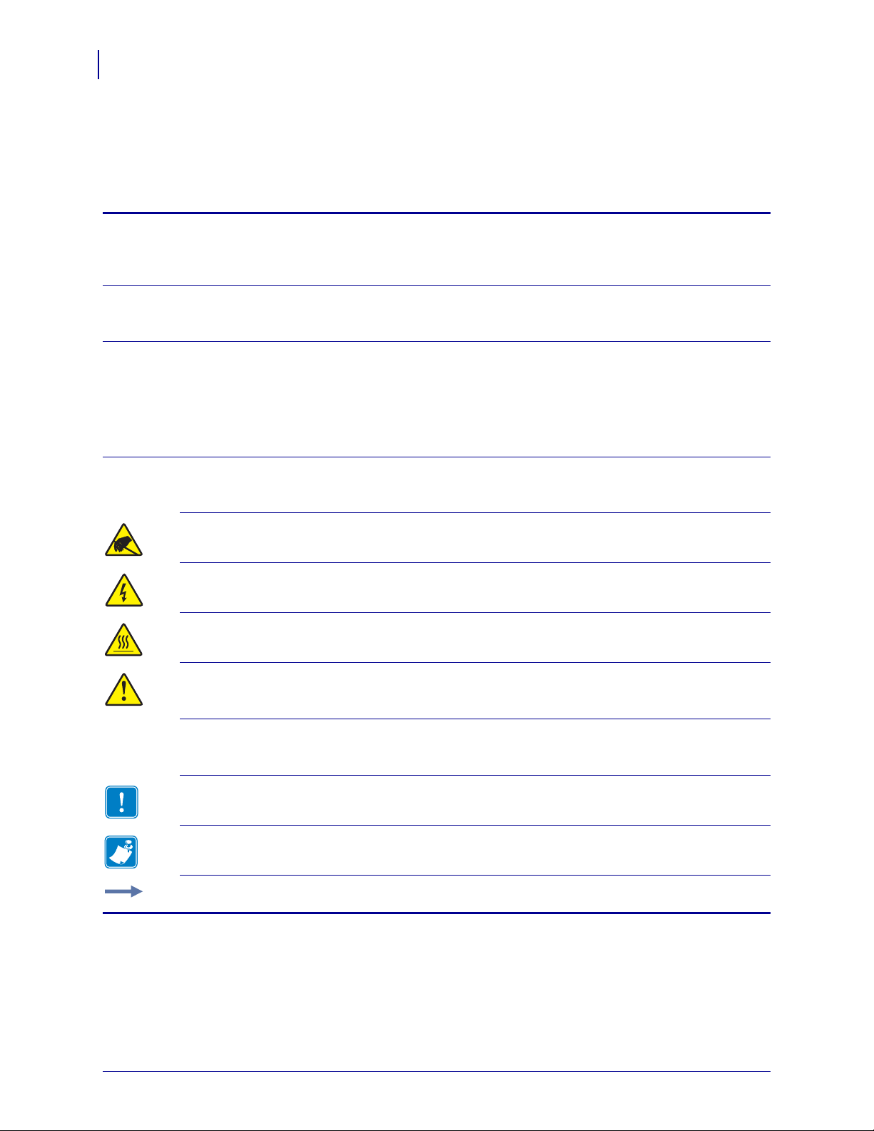
Figure 1 shows the components inside the media compartment of your printer. Depending on
printer model and the installed options, your printer may look slightly different. Familiarize
yourself with these components before continuing with the pr inter setup procedure.
Figure 1 • Printer Components
Platen roller
1
Control panel
2
Printhead assembly
3
Printhead-open lever
4
Ribbon take-up spindle
P1056468-001 11/6/12
5
Ribbon supply spindle
6
Media supply guide
7
Media supply hanger
8
Page 15
Control Panel
1 2 3 4
5
7
12 13 14
11
6
8
10
9
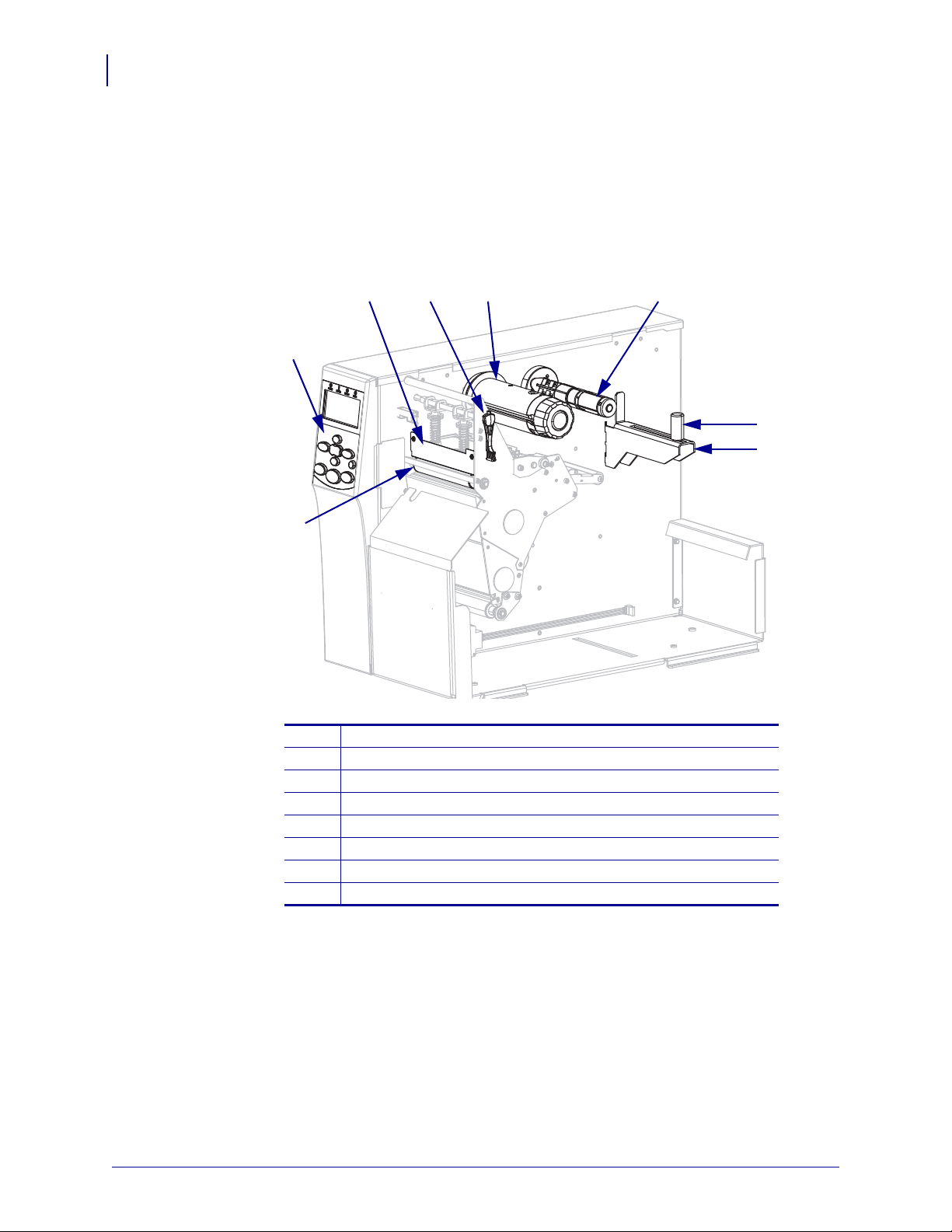
All controls and indicators for the printer are located on the control panel (Figure 2).
Figure 2 • Control Panel
Introduction
Control Panel
15
1
2
3
POWER light On when the printer is on.
PAUSE light On when the printer is paused.
ERROR light Off Normal operation—no printer errors.
On A printer error exists. Check the display for more
information.
4
DATA light Off Normal operation. No data being received or
processed.
On The printer is processing data or is printing. No data is
being received.
Blinking The printer is receiving data from or sending status
information to the host computer.
The display shows the printer’s operating status and allows the user to navigate the menu system.
5
The PLUS (+) button changes the parameter values. Common uses are to increase a value, to scroll
6
through choices, or to change values while entering the printer password.
The PREVIOUS button navigates to the previous parameter in the menus.
7
The MINUS (-) button changes the parameter values. Common uses are to decrease a value, to scroll
8
through choices, or to change the cursor position while entering the printer password.
The SETUP/EXIT button enters and exits configuration mode.
9
11/6/12 P1056468-001
Page 16

16
Introduction
Control Panel
The NEXT/SAVE button
10
• When in Setup Mode, the NEXT/SAVE button navigates to the next parameter in the menus.
• When exiting Setup Mode, the NEXT/SAVE button initiates various options. (See Exit Setup
The CALIBRATE button
11
• When the printer is paused and in non-continuous mode, the CALIBRATE button initiates a
• If the printer is in continuous mode or is not paused, this button has no effect.
The PAUSE button starts or stops printer operation when pressed.
12
The FEED button forces the printer to feed one blank label each time the button is pressed.
13
The CANCEL button cancels print jobs when the printer is paused.
14
Mode on page 19.)
SHORT CAL cal ibration, which sets th e media and web thresholds wi thout adjustin g sensor gain,
determines the label length, and feed s the media to the next web.
P1056468-001 11/6/12
Page 17
Control Panel Display
1
2
The control panel includes a display, where you can view the printer’s status or change its
operating parameters. In this section, you will l earn ho w to na vi gat e t hrou gh th e me nu syst em
and change values for menu items.
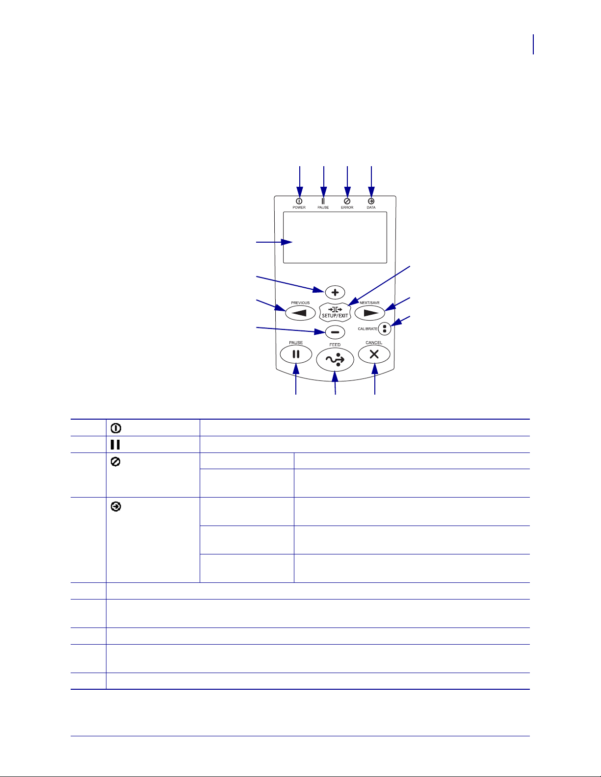
After the printer completes the power-up sequence, it moves to the Idle Display (Figure 3).
1
2
Control Panel Display
Figure 3 • Idle Display
The printer’s current status
Information that you set through Idle Display on page 95
Introduction
17
Navigating in the Display
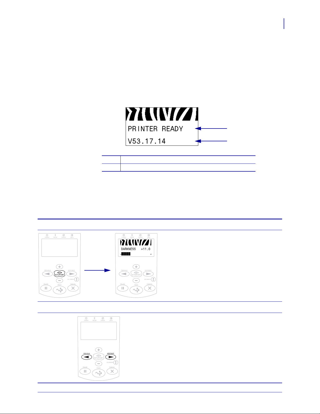
Table 2 shows the options available for navigating through the parameters in the display.
Enter Setup Mode
Scroll through the Parameters
Table 2 • Navigation
At the Idle Display (Figure 3), press SETUP to enter
Setup Mode. The printer displays the first parameter.
To scroll through the parameters, press PREVIOUS
or NEXT/SAVE.
11/6/12 P1056468-001
Page 18
Introduction
18
Control Panel Display
Perform an action
Table 2 • Navigation (Continued)
+ indicates that an action can be performed.
Press PLUS (+) to perform the specified action.
Change Parameter Values
- and + indicate that a value can be changed.
Press PLUS (+) or MINUS (-) to scroll through the
accepted values.
P1056468-001 11/6/12
Page 19

Exit Setup Mode
Table 2 • Navigation (Continued)
1. At the Idle Display (Figure 3), press SETUP to
enter Setup Mode. The printer displays the first
parameter.
2. While in Setup Mode, press SETUP/EXIT to exit
the operating parameters.
The LCD displays
3. To return to the parameters, plus PREVIOUS.
OR
Press PLUS (+) or MINUS (-) to scroll through
the exit options:
• PERMANENT—Stores values in the printer
even when power is turned off.
• TEMPORARY—Saves the changes until
power is turned off.
• CANCEL—This option cancels all changes
made since you entered Setup mode, except
for changes made to DARKNESS, TEAR
OFF , COMMUNICATION, and LANGUAGE
settings, which go into effect as soon as they
are made.
• LOAD DEFAULTS—Use this option to restore
all settings other than the network settings
back to the factory defaults. Use care when
loading defaults because you will need to
reload all settings that you changed manually.
• LOAD LAST SAVE—Loads the values from
the last permanent save.
• DEFAULT NET—Use this option to restore all
print server and network settings back to the
factory defaults. Use care when loading
defaults because you will need to reload all
settings that you changed manually.
4. Press NEXT/SAVE to select the displ ayed choice
and exit Setup Mode.
When the configuration and calibration sequence
finishes, the printer returns to the Idle Display.
Control Panel Display
SAVE CHANGES.
Introduction
19
11/6/12 P1056468-001
Page 20

Introduction
20
Control Panel Display
Changing Password-Protected Parameters
Certain parameters, including the communication parameters, are password-protected by
factory default.
Caution • Do not change password-protected parameters unless you have a complete
understanding of the parameters’ functions. If the parameters are set incorrectly, the printer
may function unpredictably.
The first time that you attempt to change a password-protected parameter, the printer displays
ENTER PASSWORD. Before you can change the parameter, you must enter the four-digit
numeric password. After you have entered the password correctly, you do not have to enter it
again unless you leave Setup mode by pressing SETUP/EXIT or by turning off (
printer.
O) the
To enter a password for a password-protected parameter, complete
these steps:
1. At the password prompt, use MINUS (-) to change the selected digit position.
2. When you have selected the digit that you wish to change, use PLUS (+) to increase the
selected digit value. Repeat these two steps for each digit of the password.
3. After entering the password, press SELECT.
The parameter you selected to change is displayed. If the password was entered correctly,
you can change the value.
Default Password Value
The default password value is 1234. The password can be changed using the Zebra
Programming Language (ZPL) command
pages (ZebraNet wired or wireless print server required).
^KP (Define Password) or using the printer’s web
Disable the Password Protection Feature
You can disable the password protection feature so that it no longer prompts you for a
password by setting the password to 0000 via the
password-protection feature, send the ZPL comma nd
1 to 9999.
^KP ZPL command. To re-enable the
^KPx, where x can be any number from
P1056468-001 11/6/12
Page 21
Operating Parameters on the Control Panel
Items in this menu are shown in the order in which they appear when you press the RIGHT
ARROW. For more information about these settings, see Print Settings on page 83.
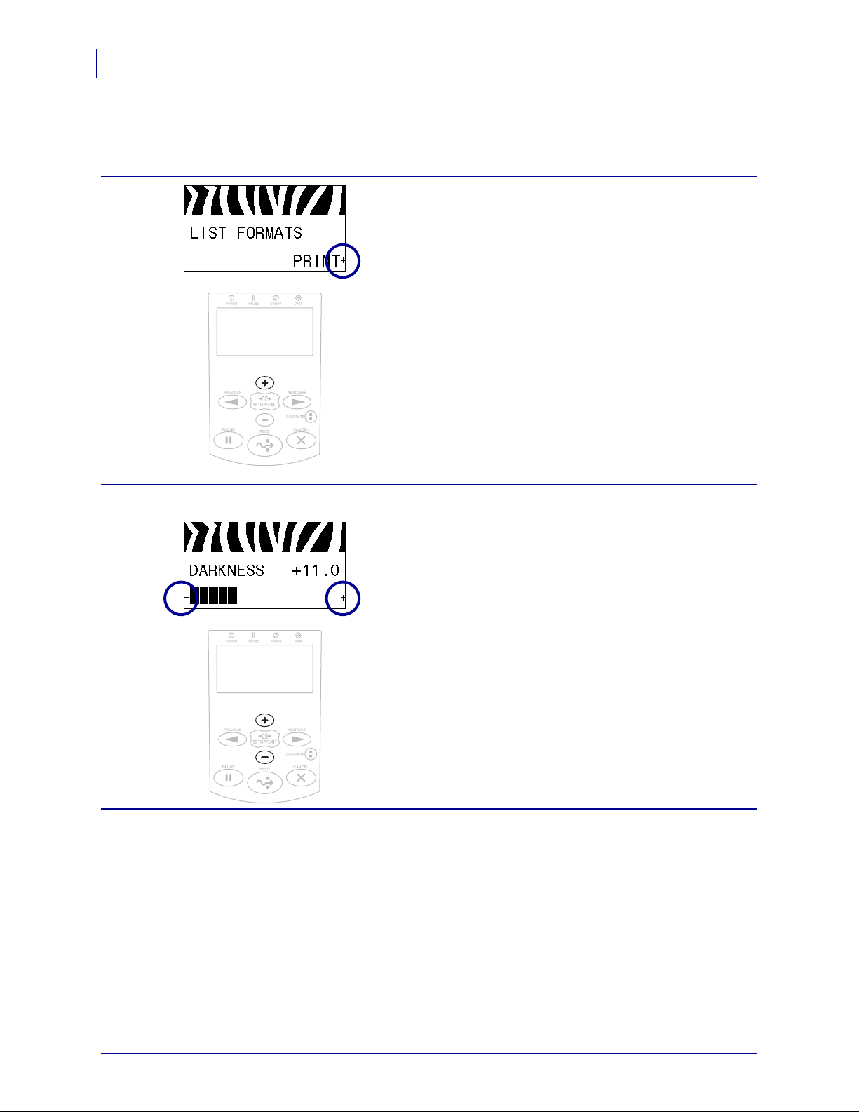
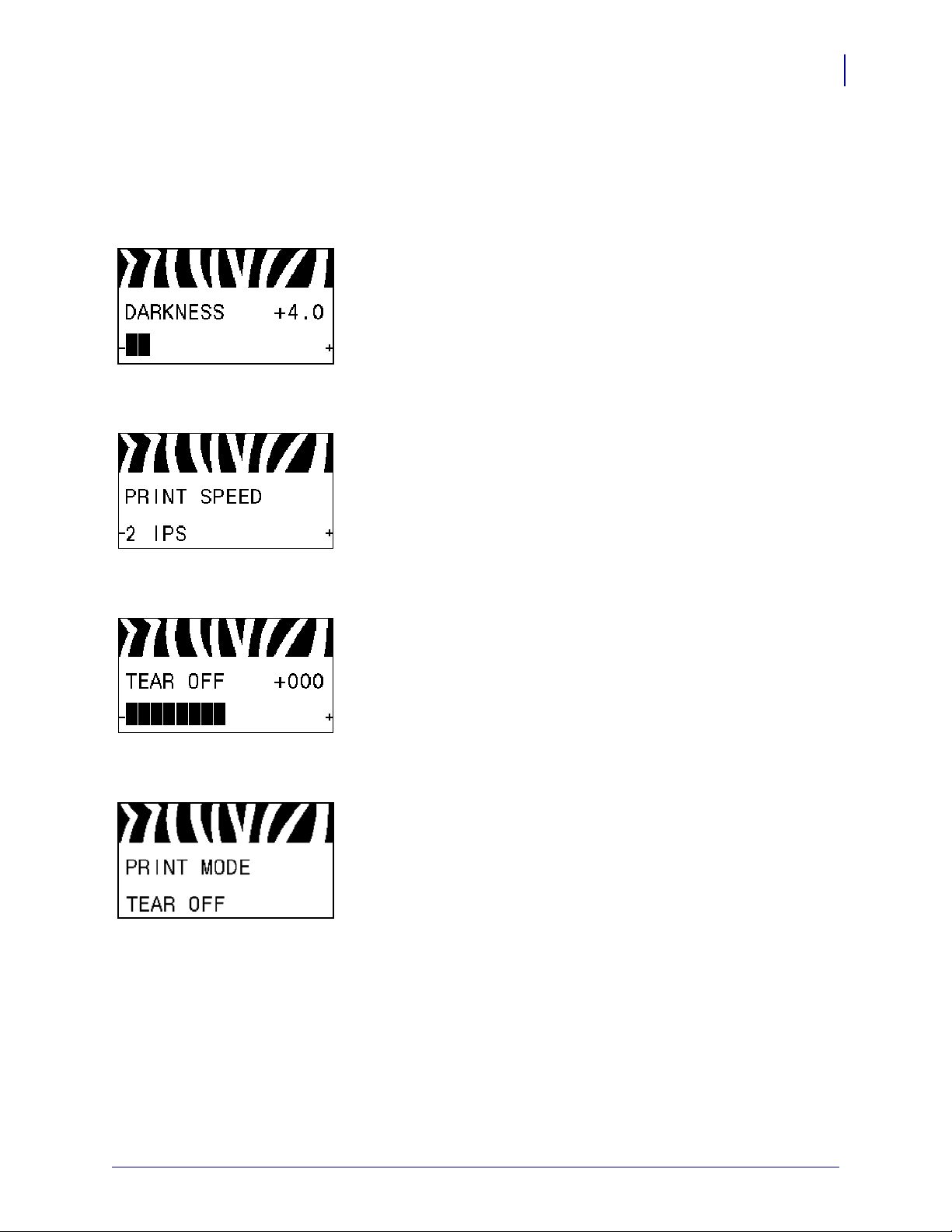
Adjust the Print Darkness
Set the darkness to the lowest setting that provides good print
quality. If you set the darkness too high, the label image may print
unclearly, bar codes may not scan correctly, the ribbon may burn
through, or the printhead may wear prematurely.
See Print Darkness on page 83 for more information.
Select the Print Speed
Select the speed for printing a label (given in inches per second).
Slower print speeds typically yield better print quality.
See Print Speed on page 83 for more information.
Introduction
Control Panel Display
21
Adjust the Tear-Off Position
If necessary, adjust the position of the media over the tear-off bar
after printing.
See Tear-Off Position on page 84 for more information.
Select the Print Mode
Select a print mode that is compatible with your printer options.
See Print Mode on page 84 for more information.
11/6/12 P1056468-001
Page 22

Introduction
22
Control Panel Display
Set the Media Type
Select the type of media that you are using.
See Media Type on page 85 for more information.
Select the Media Sensor
Select the media sensor that is appropriate for the media t hat you
are using.
See Sensor Type on page 102 for more information.
Select the Print Method
Specify if ribbon is being used. Thermal Transfer media requires
ribbon for printing while Direct Thermal media does not.
To determine if you need to use ribbon, see When to Use Ribbon
on page 49.
See Print Method on page 85 for more information.
Adjust the Print Width
Specify the width of the labels being used.
See Print Width on page 85 for more information.
Set the Maximum Label Length
Set the maximum label length to a value that is at least 1.0 in.
(25.4 mm) greater than the actual label length plus the interlabel
gap. If you set the value to one that is smaller than the la bel length ,
the printer assumes that continuous media is loaded, and the printer
cannot calibrate.
See Maximum Label Length on page 86 for more information.
P1056468-001 11/6/12
Page 23
Introduction
Control Panel Display
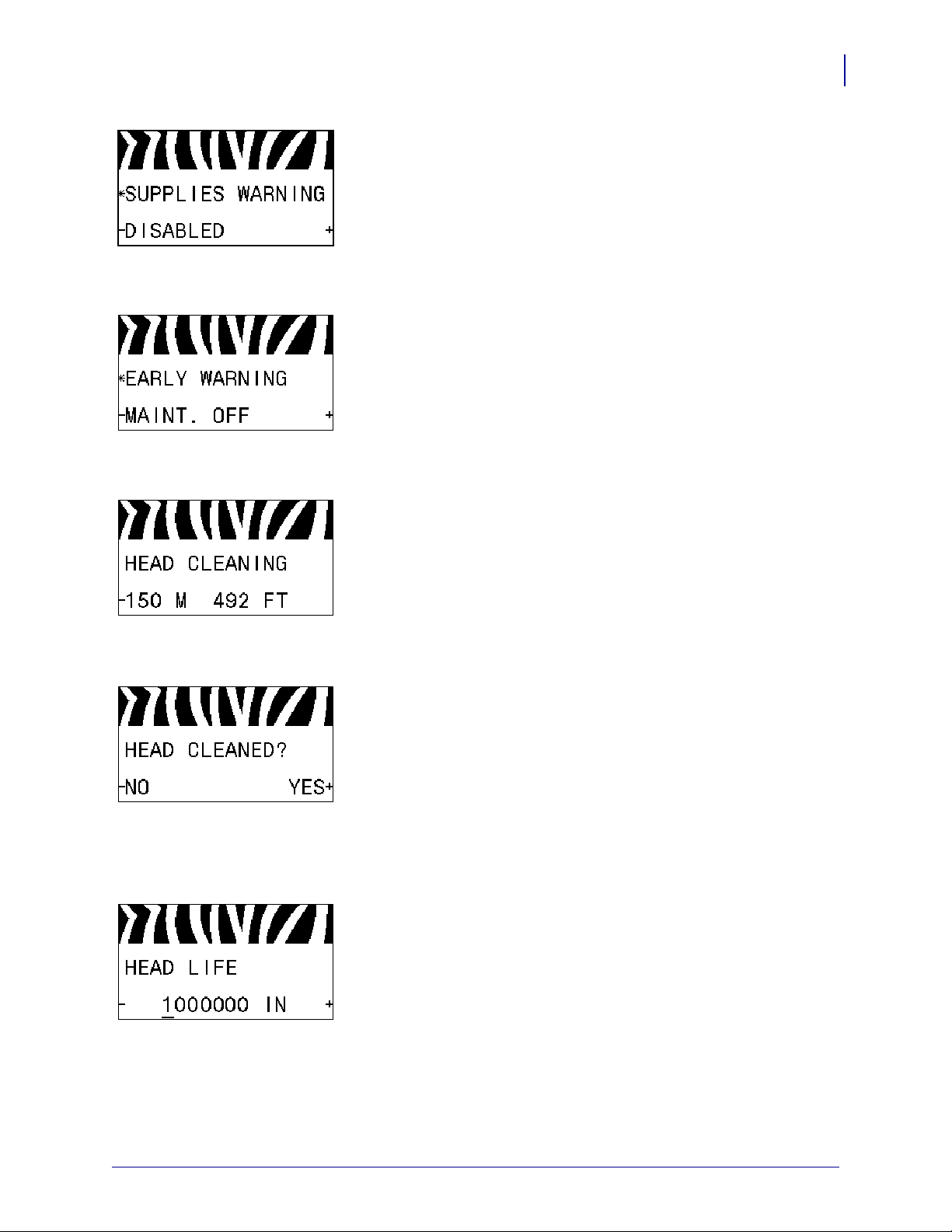
Set Supplies Low Warning
When this feature is enabled, the printer provides warnings when
the media or ribbon is reaching near the end of the roll.
See Supplies Low Warning on page 89 for more information.
Set Early Warning for Maintenance
When this feature is enabled, the printer provides warnings when
the printhead needs to be cleaned.
See Early Warning for Maintenance on page 89 for more
information.
Set Printhead Cleaning Interval*
23
When Early Warning for Maintenance is enabled, set this value to
the length of the media or ribbon roll that you are using.
See Printhead Cleaning Interval on page 89 for more information.
* This parameter appears only if Early Warning for Maintenance
is enabled.
Reset Printhead Cleaning Counter for Early Warning*
• If you received the message WARNING CLEAN PRINTHEAD,
clean the printhead, and then press PLUS to select
YES to reset
the Early Warning for Maintenance printhead cleaning counter.
• If you have not cleaned the printhead, press MINUS to select
NO.
* This parameter appears only if Early Warning for Maintenance
is enabled.
Set Printhead Life Expectancy*
When Early Warning for Maintenance is enabled, set this value to
the number of inches of media that the printhead is expected to
print.
See Printhead Life Expectancy on page 89 for more information.
* This parameter appears only if Early Warning for Maintenance
is enabled.
11/6/12 P1056468-001
Page 24
Introduction
24
Control Panel Display
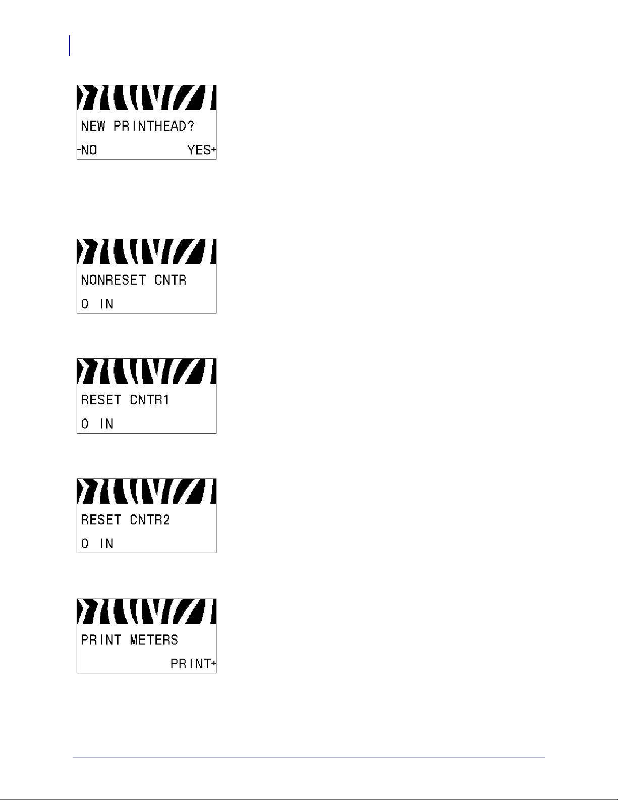
Reset New Printhead Counter for Early Warning*
• If you received the message WARNING REPLACE HEAD,
replace the printhead, and then press PLUS (+) to select
YES to
reset the Early Warning for Maintenance printhead replacement
counter.
• If you have not replaced the printhead, press MINUS (-) to
NO.
select
* This parameter appears only if Early Warning for Maintenance
is enabled.
View the Non-Resettable Counter
This parameter displays the total length of media that the printer
has printed.
See Non-Resettable Counter on page 90 for more information.
View User-Controlled Counter 1
This parameter displays the total length of media that the printer
has printed since this counter was la st reset.
See User-Controlled Counters on page 90 for more information.
View User-Controlled Counter 2
This parameter displays the total length of media that the printer
has printed since this counter was la st reset.
See User-Controlled Counters on page 90 for more information.
Print Counter Readings
Prints a label that lists the odometer readings for the following:
• the non-resettable counter
• the two user-controlled counters
• the Early Warning for Maintenance counters, which indicate
when the printhead was last cleaned and the printhead life (If
the Early Warning for Maintenance feature is disabled, the
counters related to it do not print.)
See Print Counter Readings on page 90 for more information.
P1056468-001 11/6/12
Page 25
Introduction
Control Panel Display
Print Font List
This option prints a label that lists the available fonts in the prin ter ,
including standard printer fonts plus any op tional fo nts. Fon ts may
be stored in RAM or Flash memory.
See Print Information on page 91 for more information.
Print Bar Code List
This option prints a label that lists the available bar codes in the
printer. Bar codes may be stored in RAM or Flash memory.
See Print Information on page 91 for more information.
Print Image List
25
This option prints a label that lists the available images stored in
the printer’s RAM, Flash memory, or optional memory card.
See Print Information on page 91 for more information.
Print Format List
This option prints a label that lists the available formats stored in
the printer’s RAM, Flash memory, or optional memory card.
See Print Information on page 91 for more information.
Print Configuration Label
This option prints a configuration label (see Figure 13
on page 149), which lists the current printer configuration.
See Print Information on page 91 for more information.
11/6/12 P1056468-001
Page 26
Introduction
26
Control Panel Display
Print Network Configuration Label
This option prints a configuration label (see Figure 14
on page 149), which lists the settings for any print server that is
installed.
See Print Information on page 91 for more information.
Print All Labels
This option prints labels that list the available fonts, bar codes,
images, formats, and the current printer and network
configurations.
See Print Information on page 91 for more information.
Initialize Flash Memory
This option erases all previously stored information from Flash
memory.
1. If prompted for a password, enter the printer password. For
instructions, see Changing Password-Protected Parameters
on page 20.
The display shows
2. Press PLUS (+) to select YES.
INITIALIZE FLASH?
The display shows ARE YOU SURE?.
3. Do you want to continue?
• Press MINUS (-) to select NO to cancel the request and return
INITIALIZE FLASH prompt.
to the
• Press PLUS (+) to select YES and begin initialization.
When initialization is complete, the control panel displays
INITIALIZING COMPLETED.
Note • Initializing memory can take several minutes.
See Initialize Flash Memory on page 91 for more information.
Print a Sensor Profile
Use this menu item to print a sensor profile.
See Print a Sensor Profile on page 91 for more information.
P1056468-001 11/6/12
Page 27
Introduction
Control Panel Display
Calibrate the Media and Ribbon Sensors
Use this menu item to adjust the sensitivity of the media and
ribbon sensors.
See Media and Ribbon Sensor Calibration on page 94 for more
information. For instructions on how to perform a calibration
procedure, see Calibrate the Ribbon and Media Sensors Manually
on page 106.
Set Parallel Communications
Select the communications port that matches the one being used by
the host computer.
See Parallel Communications on page 103 for more information.
Set Serial Communications
27
Select the communications port that matches the one being used by
the host computer.
See Parallel Communications on page 103 for more information.
Set the Baud Rate
Select the baud value that matches the one being used by the host
computer.
See Baud Rate on page 104 for more information.
Set the Data Bits Value
Select the data bits value that matches the one being used by the
host computer.
See Data Bits on page 104 for more information.
11/6/12 P1056468-001
Page 28

Introduction
28
Control Panel Display
Set the Parity Value
Select the parity value that matches the on e be ing used by the host
computer.
See Parity on page 104 for more information.
Set the Host Handshake Protocol Value
Select the handshake protocol that matches the one being used by
the host computer.
See Host Handshake on page 105 for more information.
Set the Zebra Protocol Value
Protocol is a type of error checking system. Depending on the
selection, an indicator may be sent from the printer to the host
computer signifying that data has been received. Select the
protocol that is requested by the host computer.
See Protocol on page 105 for more information.
Set the Network ID
This parameter assigns a unique number to the printer when the
printer is operating in an RS422/485 multi-drop network
environment (an external RS422/485 adapter is required). This
gives the host computer the means to address a specific printer.
This does not affect TCP/IP or IPX networks. Set a unique network
ID number for this printer.
See Network ID on page 105 for more information.
Enable Communication Diagnostics Mode
Use this diagnostics tool to cause the printer to output the
hexadecimal values for all data received by the printer.
See Communication Diagnostics Mode on page 94 for more
information.
P1056468-001 11/6/12
Page 29
Introduction
Control Panel Display
Set the Control Character Value
Set the control prefix character to match what is used in your label
formats.
See Control Character on page 100 for more information.
Set the Format Command Prefix Value
Set the format command prefix character to match what is used in
your label formats.
See Command Character on page 101 for more information.
Set the Delimiter Character Value
29
Set the delimiter character to match what is used in your label
formats.
See Delimiter Character on page 101 for more information.
Set the ZPL Mode
Select the ZPL mode that matches what is used in your label
formats.
See ZPL Mode on page 101 for more information.
Set the Power-Up Action
Set the action for the printer to take during the power-up sequence.
See Power-Up Action on page 92 for more information.
11/6/12 P1056468-001
Page 30
Introduction
30
Control Panel Display
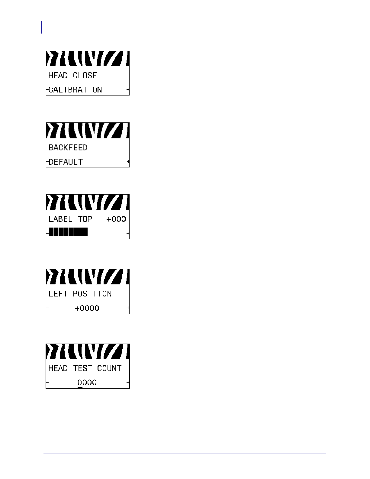
Set the Head-Close Action
Set the action for the printer to take when you close the printhead.
See Head-Close Action on page 92 for more information.
Set the Backfeed Sequence
This parameter sets when label backfeed occurs after a label is
removed in some print modes. It has no effect in Rewind mode.
This setting is superseded by ~JS when received as part of a label
format.
See Backfeed Sequence on page 87 for more information.
Adjust the Label Top Position
This parameter adjusts the print position vertically on the label.
Positive numbers adjust the label top position farther down the
label (away from the printhead) by the specified number of dots.
Negative numbers adjust the position up the label (toward the
printhead).
See Label Top Position on page 87 for more information.
Adjust the Label Left Position
If necessary, shift the print position horizontally on the label.
Positive numbers move the left edge of the image toward the
center of the label by the number of dots selected, while negative
numbers move the left edge of the image toward the left edge of
the label.
See Label Left Position on page 87 for more information.
Set the Head Test Cou nt*
The printer periodically performs a test of the printhead
functionality. This parameter establishes how many labels are
printed between these internal tests.
See Head Test Count on page 87 for more information.
P1056468-001 11/6/12
Page 31

Introduction
Control Panel Display
Set the Reprint Mode
When reprint mode is enabled, you can reprint the last label printed
either by issuing certain commands or by pressing the LEFT
ARROW on the control panel.
See Reprint Mode on page 88 for more information.
View Sensor Settings
The following parameters are automatically set during the
calibration procedure and should be changed only by a qualified
service technician.
31
Select Format Conversion Scaling Factor
Selects the bitmap scaling factor. The first number is the original
dots per inch (dpi) value; the second, the dpi to which you would
like to scale.
See Format Conversion on page 94 for more information.
11/6/12 P1056468-001
Page 32

Introduction
32
Control Panel Display
Select the Idle Display
Select the information shown on the printer’s display when the
printer is idle.
See Idle Display on page 95 for more information.
Set the Real-Time Clock (RTC) Date
This parameter allows you to set the date to display in the Idle
Display.
See RTC Date on page 95 for more information.
Set the Real-Time Clock (RTC) Time
This parameter allows you to set the date to display in the Idle
Display.
See RTC Time on page 95 for more information.
Run the Specified ZBI Program*
• To run the ZBI program selected by the previous menu item,
press PLUS (+).
• If you did not replace the ribbon, press MINUS (-) to select
CANCEL, or press the LEFT ARROW or RIGHT ARROW
to move to another parameter.
See Run a ZBI Program on page 95 for more information.
* This menu item appears only if ZBI is enabled on your printer
and no ZBI program is running.
Select the Primary Network Device
This parameter determines which device should be considered
primary in the active device selection.
See Primary Network on page 96 for more information.
P1056468-001 11/6/12
Page 33

Introduction
Control Panel Display
View if IP Settings Are Loaded from the Printer or Print
Server
This parameter tells whether to use the printer’s or the print
server’s LAN/WLAN settings at power-up. The default is to use
the printer’s settings.
See Load from External Device on page 96 for more information.
View the Active Print Server*
This menu item displays which print server is being used. Thi s tells
which device’s settings such as IP protocol and IP address are
being displayed under those menu items.
* This menu item, which cannot be modified from the control
panel, appears only if a wired or wireless print server is
installed in your printer.
Set the IP Resolution Method*
33
This parameter tells if the user (permanent) or the server (dynamic)
selects the IP address. If a dynamic option is chosen, this
parameter tells the method(s) by which the wired or wireless print
server receives the IP address from the server .
See IP Protocol on page 97 for more information.
* This menu item appears only if a wired or wireless print server
is installed in your printer.
Set the Printer’s IP Address*
View and, if necessary, change the printer’s IP address.
Changes are saved only if IP PROT OC OL is set to
PERMANENT.
To allow any saved changes to take effect, use RESET NETWOR K
on page 35 to reset the print server.
See IP Address on page 97 for more information.
* This menu item appears only if a wired or wireless print server
is installed in your printer.
11/6/12 P1056468-001
Page 34

Introduction
34
Control Panel Display
Set the Subnet Mask*
View and, if necessary, change the subnet mask.
Changes are saved only if IP PROT OC OL is set to
PERMANENT.
To allow any saved changes to take effect, use RESET NETWOR K
on page 35 to reset the print server.
See Subnet Mask on page 98 for more information.
* This menu item appears only if a wired or wireless print server
is installed in your printer.
Set the Default Gateway*
View and, if necessary, change the default gateway.
Changes are saved only if IP PROT OC OL is set to
PERMANENT.
To allow any saved changes to take effect, use RESET NETWOR K
on page 35 to reset the print server.
See Default Gateway on page 98 for more information.
* This menu item appears only if a wired or wireless print server
is installed in your printer.
View the MAC Address*
View the Media Acc ess Control (MAC) address of the print server
that is installed in the printer (wired or wireless).
See MAC Address on page 98 for more information.
* This menu item, which cannot be modified from the control
panel, appears only if a wired or wireless print server is
installed in your printer.
View the ESSID Value*
The Extended Service Set Identification (ESSID) is an identifier
for your wireless network. This setting, which cannot be modified
from the control panel, gives the ESSID for the current wireless
configuration.
See ESSID on page 99 for more information.
* This menu item, which cannot be modified from the control
panel, appears only if a wir eless print server is instal led in your
printer.
P1056468-001 11/6/12
Page 35

Introduction
Control Panel Display
Reset the Network Settings*
This option resets the wired or wireless print server. Y ou must reset
the print server to allow any changes to the network se ttings to take
effect.
See Reset Network on page 99 for more information.
* This menu item appears only if a wired or wireless print server
is installed in your printer.
Specify the Password Level
This parameter allows you to select whether certain factoryselected menu items or all menu items are password protected.
See Password Level on page 95 for more information.
35
11/6/12 P1056468-001
Page 36

Introduction
36
Control Panel Display
Select the Display Language
If necessary, change the language that the printer displays.
See Language on page 100 for more information.
Note • The selections for this parameter are displayed in
the actual languages to make it easier for you to find one
that you are able to read.
P1056468-001 11/6/12
Page 37

Printer Setup and
Operation
This section assists the technician with initial setup and operation of the printer.
2
Contents
Handling the Printer . . . . . . . . . . . . . . . . . . . . . . . . . . . . . . . . . . . . . . . . . . . . . . . . . . . . . 38
Unpack and Inspect the Printer . . . . . . . . . . . . . . . . . . . . . . . . . . . . . . . . . . . . . . . . . . 38
To Store the Printer . . . . . . . . . . . . . . . . . . . . . . . . . . . . . . . . . . . . . . . . . . . . . . . . . . . 38
To Ship the Printer . . . . . . . . . . . . . . . . . . . . . . . . . . . . . . . . . . . . . . . . . . . . . . . . . . . . 38
Select a Location for the Printer. . . . . . . . . . . . . . . . . . . . . . . . . . . . . . . . . . . . . . . . . . . . 39
Select a Data Communication Interface. . . . . . . . . . . . . . . . . . . . . . . . . . . . . . . . . . . . . . 40
Data Cables. . . . . . . . . . . . . . . . . . . . . . . . . . . . . . . . . . . . . . . . . . . . . . . . . . . . . . . . . 42
Connect the Printer to a Power Source . . . . . . . . . . . . . . . . . . . . . . . . . . . . . . . . . . . . . . 43
Power Cord Specifications. . . . . . . . . . . . . . . . . . . . . . . . . . . . . . . . . . . . . . . . . . . . . . 44
Install the Control Panel Keypad Cover. . . . . . . . . . . . . . . . . . . . . . . . . . . . . . . . . . . . . . 46
Select a Print Mode . . . . . . . . . . . . . . . . . . . . . . . . . . . . . . . . . . . . . . . . . . . . . . . . . . . . . 51
Load the Ribbon. . . . . . . . . . . . . . . . . . . . . . . . . . . . . . . . . . . . . . . . . . . . . . . . . . . . . . . . 54
Load the Media . . . . . . . . . . . . . . . . . . . . . . . . . . . . . . . . . . . . . . . . . . . . . . . . . . . . . . . . 59
11/6/12 P1056468-001
Page 38

Printer Setup and Operation
38
Handling the Printer
Handling the Printer
This section describes how to handle your printer.
Unpack and Inspect the Printer
Important • Zebra Technologies is not responsible for any damage incurred during the
shipment of the equipment and will not repair this damage under warranty.
When you receive the printer, do the following:
1. Immediately unpack the printer.
2. Check all exterior surfaces for damage.
3. Raise the media door, and inspect the media compartment for damage to components.
4. If you discover shipping damage during inspection, do the following:
• Immediately notify the shipping company, and file a damage report.
• Keep all packaging material for shipping company inspection.
• Notify your authorized Zebra reseller.
To Store the Printer
If you are not placing the printer into immediate operation, repackage it using the original
packing materials. You may store the printer under the following conditions:
• Temperature: –40°F to 140°F (–40° to 60°C)
• Relative humidity: 5% to 85% non-condensing
To Ship the Printer
Save all packing materials in case you need to ship the printer in the future.
To ship the printer, do the following:
1. Turn off (O) the printer, and disconnect all cables.
2. Remove any media, ribbon, or loose objects from the printer interior.
3. Close the printhead.
4. Carefully pack the printer into the original container or a suitable alternate container to
avoid damage during transit. A shipping container can be purchased from Zebra if the
original packaging has been lost or destroyed.
P1056468-001 11/6/12
Page 39

Select a Location for the Printer
Select a location for the printer that meets these conditions:
• Surface: The surface where the printer will be located must be solid, level, and of
sufficient size and strength to hold the printer.
• Space: The area where the printer will be located must include enough space for
ventilation and for accessing the printer components and connectors. To allow for proper
ventilation and cooling, leave open space on all sides of the printer.
Caution • Do not place any padding or cushioning material behind or under the printer
because this restricts air flow and could cause the printer to overheat.
• Power: The printer should be within a short distance of an appropriate power outlet that is
easily accessible.
• Data communication interfaces: The printer must be within range of your WLAN radio
(if applicable) or within an acceptable range fo r other connectors to reach your data source
(usually a computer). For more information on maximum cable lengths and configuration,
see Table 4 on page 41.
Printer Setup and Operation
Select a Location for the Printer
39
• Operating conditions: Your printer is designed to function in a wide range of
environmental and electrical conditions, including a warehouse or factory floor. Table 3
shows the temperature and relative humidity requirements for the printer when it is
operating.
Table 3 • Operating Temperature and Humidity
Mode Temperature Relative Humidity
Thermal Transfer 41° to 104°F (5° to 40°C) 20 to 85% non-condensing
Direct Thermal 32° to 104°F (0° to 40°C)
11/6/12 P1056468-001
Page 40

Printer Setup and Operation
40
Select a Data Communication Interface
Select a Data Communication Interface
You may connect your printer to a computer using one or more of the available connections.
The standard connections are shown in Figure 4. A ZebraNet wired or wireless print server
option or a parallel port may also be present on your printer.
Figure 4 • Communication Interfaces
Serial port
Internal wired Ethernet print server
USB port
Parallel port
Table 4 on page 41 provides basic information about data communication interfaces that you
can use to connect your printer to a computer. You may send label formats to the printer
through any data communication interface that is available. Select an interface that is
supported by both your printer and your computer or your Local Area Network (L AN ).
Caution • Ensure that the printer power is off (O) before connecting data communications
cables. Connecting a data communications cable while the power is on (
printer.
I) may damage the
P1056468-001 11/6/12
Page 41

Select a Data Communication Interface
Table 4 • Data Communication Interfaces
Printer Setup and Operation
41
Interface
Standard or
Option
Description
RS-232 Serial Standard Limitations and Requirements
• Maximum cable length of 50 ft (15.24 m).
• You may need to change printer parameters to match the host
computer.
• You need to use a null-modem adaptor to connect to the printer
if using a standard modem cable.
Connections and Configuration The baud rate, number of
data and stop bits, the parity, and the XON/XOFF or DTR control
must match those of the host computer.
USB Standard Limitations and Requirements
• Maximum cable length of 16.4 ft (5 m).
• No printer parameter changes required to match the host
computer.
Connections and Configuration No additional
configuration is necessary.
8-bit Parallel data
interface
Standard Limitations and Requirements
• Maximum cable length of 10 ft (3 m).
• Recommended cable length of 6 ft (1.83 m).
• No printer parameter changes required to match the host
computer.
• A wired or wireless print server (if installed) takes up this port
on the printer.
Wired Ethernet print
server
Connections and Configuration No additional
configuration is necessary.
Option Limitations and Requirements
• Can print to the printer from any computer on your LAN.
• Can communicate with the printer through the printer’s web
pages.
• The printer must be configured to use your LAN.
• A parallel connection or a wireless print server (if installed)
takes up this port on the printer.
Caution • Be careful not to plug a USB cable into a wired
Ethernet print server connector on the printer because doing so
will damage the Ethernet connector.
Connections and Configuration Refer to the ZebraNet
Wired and Wireless Print Servers User Guide for configuration
instructions. A copy of this manual is ava ilable at
http://www.zebra.com/manuals or on the user CD that came with
your printer.
Note • To use this connection, you may need to remove a
factory-installed plug that is designed to keep someone
from accidentally plugging a USB connector into this port.
11/6/12 P1056468-001
Page 42

Printer Setup and Operation
42
Select a Data Communication Interface
Table 4 • Data Communication Interfaces (Continued)
Interface
Standard or
Option
Description
Wireless print server Option Limitations and Requirements
• Can print to the printer from any computer on your Wireless
Local Area Network (WLAN).
• Can communicate with the printer through the printer’s web
pages.
• The printer must be configured to use your WLAN.
• A parallel connection or a wired print server (if install ed) takes
up this port on the printer.
Configuration Refer to the ZebraNet Wired and Wirel ess Print
Servers User Guide for configuration instructions. A copy of this
manual is available at http://www.zebra.com/manuals or on the
user CD that came with your printer.
Data Cables
You must supply all data cables for your application.
Ethernet cables do not require shielding, but all other data cables must be fully shielded and
fitted with metal or metallized connector shel ls. Unshie lde d data cables may increase ra dia ted
emissions above the regulated limits.
To minimize electrical noise pickup in the cable:
• Keep data cables as short as possible.
• Do not bundle the data cables tightly with the power cords.
• Do not tie the data cables to power wire conduits.
P1056468-001 11/6/12
Page 43

Connect the Printer to a Power Source
115 V AC
230 V AC
The AC power cord must have a three-prong female connector on one end that plugs into the
mating AC power connector at the rear of the printer. If a power cable was not included with
your printer, refer to Power Cord Specifications on page 44.
Caution • For personnel and equipment safety, always use an approved three-conductor
power cord specific to the region or country intended for installation. This cord must use an
IEC 320 female connector and the appropriate region-specific three-conductor grounded
plug configuration.
To connect the printer to a power source, complete these steps:
1. Plug the female end of the A/C power cord into the A/C power connector on the back of
the printer.
Printer Setup and Operation
Connect the Printer to a Power Source
43
2. Plug the male end of the A/C power cord into an appropriate power outlet.
11/6/12 P1056468-001
Page 44

Printer Setup and Operation
44
Connect the Printer to a Power Source
3. Turn on (I) the printer.
The printer boots up and performs a self-test.
Power Cord Specifications
Caution • For personnel and equipment safety, always use an approved three-conductor
power cord specific to the region or country intended for installation. This cord must use an
IEC 320 female connector and the appropriate region-specific, three-conductor grounded
plug configuration.
Depending on how your printer was ordered, a power cord may or may not be included. If one
is not included or if the one included is not suitable for your requirements, see Figure 5 and
refer to the following guidelines:
• The overall cord length must be less than 9.8 ft. (3 m).
• The cord must be rated for a minimum of 10 A, 250 V.
• The chassis ground (earth) must be connected to ensure safety and reduce electromagne tic
interference.
P1056468-001 11/6/12
Page 45

Printer Setup and Operation
3
1
2
4
Connect the Printer to a Power Source
Figure 5 • Power Cord Specifications
45
AC power plug for your country—This should bear the certification
1
mark of at least one of the known international safety organizations
(Figure 6).
3-conductor HAR cable or other cable approved for your country.
2
IEC 320 connector—This should bear the certification mark of at
3
least one of the known international safety organizations (Figure 6).
Length ≤ 9.8 ft. (3 m). Rating 10 Amp minimum, 250 VAC.
4
Figure 6 • International Safety Organization Certification Symbols
11/6/12 P1056468-001
Page 46

Printer Setup
46
Install the Control Panel Keypad Cover
Install the Control Panel Keypad Cover
A protective cover for the control panel keypad is provided with your printer (Figure 7). Install
this optional cover if your printer will operate in a moist or dirty environment. This will help to
protect the keypad from damage.
Figure 7 • Control Panel Keypad Cover
To install the control panel keypad cover, complete these steps:
1. Remove the paper backing from the control panel keypad cover to expose the adhesive.
2. Carefully align the cover over the keypad. Press to make the cover adhere to the printer.
P1056468-001 105SLPlus™ User Guide 11/6/12
Page 47

Types of Media
Important • Zebra strongly recommends the use of Zebra-brand supplies for continuous
high-quality printing. A wide range of paper, polypropylene, polyester, and vinyl stock has
been specifically engineered to enhance t he p rint ing c apabi lities of the pri nter an d to pre vent
premature printhead wear. To purchase supplies, go to http://www.zebra.com/howtobuy.
Your printer can use various types of media:
• Standard media—Most standard media uses an adhesive backing that sticks individual
labels or a continuous length of labels to a liner. Standard media can come on rolls or in a
fanfold stack (Table 5).
• Tag stock—Tags are usually made from a heavy paper. Tag stock does not have adhesive
or a liner, and it is typically perforated between tags. Tag stock can come on rolls or in a
fanfold stack (Table 5).
Table 5 • Roll and Fanfold Media
Media Type How It Looks Description
Printer Setup and Operation
Types of Media
47
Non-Continuous
Roll Media
Roll media is wound on a 3-in. (76-mm) core. Individual
labels or tags are separated by one or more of the following
methods:
• Web media separates labels by gaps, holes, or notc hes.
• Black mark media uses pre-printed black marks on the
back side of the media to indicate label separations.
• Perforated media has perforations that allow the labels or
tags to be separated from each other easily. The media may
also have black marks or other separations between labels
or tags.
11/6/12 P1056468-001
Page 48

Printer Setup and Operation
48
Types of Media
Table 5 • Roll and Fanfold Media (Continued)
Media Type How It Looks Description
Non-Continuous
Fanfold Media
Continuous
Roll Media
Fanfold media is folded in a zigzag pattern. Fanfold media can
have the same label separations as non-continuous roll media.
The separations would fall on or near the folds.
Roll media is wound on a 3-in. (76-mm) core.
Continuous roll media does not have gaps, holes, notches , o r
black marks to indicate label separations. This allows the
image to be printed anywhere on the label. Sometimes a cutter
is used to cut apart individual labels.
P1056468-001 11/6/12
Page 49

Ribbon Overview
Outside Inside
Ribbon is a thin film that is coated on one side with wax, resin, or wax resin, which is
transferred to the media during the thermal transfer process. The media determines whether
you need to use ribbon and how wide the ribbon must be.
When ribbon is used, it must be as wide as or wider than the media being used. If the ribbon is
narrower than the media, areas of the printhead are unprotected and subject to premature wear.
When to Use Ribbon
Thermal Transfer media requires ribbon for printing while Direct Thermal media does not.
To determine if ribbon must be used with a particular media, perform a media scratch test.
To perform a media scratch test, complete these steps:
1. Scratch the print surface of the media rapidly with your fingernail.
2. Did a black mark appear on the media?
Printer Setup and Operation
Ribbon Overview
49
If a black mark... Then the media is...
Does not appear on the media Thermal tr ansfer. A ribbon is required.
Appears on the media Direct thermal. No ribbon is required.
Coated Side of Ribbon
Ribbon can be wound with the co ated si de on the i nside or outsi de ( Figure 8). This printer can
only use ribbon that is coated on t he outside. If you are unsure which side of a particular roll of
ribbon is coated, perform an adhesive test or a ribbon scratch t est to determine which side is
coated.
Figure 8 • Ribbon Coated on Outside or Inside
11/6/12 P1056468-001
Page 50

Printer Setup and Operation
50
Ribbon Overview
Adhesive Test
To perform an adhesive test, complete these steps:
If you have labels available, perform the adhesive test to determine which side of a ribbon is
coated. This method works well for ribbon that is already installed.
1. Peel a label from its liner.
2. Press a corner of the sticky side of the label to the outer surface of the roll of ribbon.
3. Peel the label off of the ribbon.
4. Observe the results. Did flakes or particles of ink from the ribbon adhere to the label?
If ink from the ribbon... Then...
Adhered to the label The ribbon is coated on the outside and can be
used in this printer.
Did not adhere to the label The ribbon is coated on the inside and cannot
be used in this printer.
To verify this, repeat the test on the other
surface of the roll of ribbon.
Ribbon Scratch Test
Perform the ribbon scratch test when labels are unavailable.
To perform a ribbon scratch test, complete these steps:
1. Unroll a short length of ribbon.
2. Place the unrolled section of ribbon on a piece of paper with the outer surface of the
ribbon in contact with the paper.
3. Scratch the inner surface of the unrolled ribbon with your fingernail.
4. Lift the ribbon from the paper.
5. Observe the results. Did the ribbon leave a mark on the paper?
If the ribbon... Then...
Left a mark on the paper The ribbon is coated on the outside and can be
used in this printer.
Did not leave a mark on the
paper
The ribbon is coated on the inside and cannot
be used in this printer.
To verify this, repeat the test on the other
surface of the roll of ribbon.
P1056468-001 11/6/12
Page 51

Select a Print Mode
fanfold media in Tear-Off mode
(bottom feed)
fanfold media in Tear-Off mode
(rear feed)
roll media in Tear-Off mode
Use a print mode that matches the media being used and the printer options available
(Table 6).
Table 6 • Print Modes and Printer Options
Print Mode When to Use/Printer Options Required Printer Actions
Printer Setup and Operation
Select a Print Mode
51
Tear-Off
(default setting)
Use for most applications. This mode can
be used with any printer options and most
media types.
The printer prints label formats as it
receives them. The printer operator can tear
off the printed labels any time after they
print.
11/6/12 P1056468-001
Page 52

Printer Setup and Operation
52
Select a Print Mode
Table 6 • Print Modes and Printer Options
Print Mode When to Use/Printer Options Required Printer Actions
Peel-Off Use when the printer has the Rewind option
if you want to remove the labels from the
liner one label at a time.
Red solid lines = media, Blue dotted lines = backing only
Rewind Use when the p rinter has the Rewi nd option
if you want to save the labels without
separating them or removing them from
their backing.
The printer peels the label from the liner
during printing and then pauses until the
label is removed. The liner winds onto the
rewind spindle.
The printer prints without pausing between
labels. The media is wound onto the rewind
spindle after printing.
P1056468-001 11/6/12
Page 53

Table 6 • Print Modes and Printer Options
Print Mode When to Use/Printer Options Required Printer Actions
Printer Setup and Operation
Select a Print Mode
53
Cutter Use when the printer has a cutter option if
you want the labels to be cut apart.
The printer prints a label and then cuts it
free.
11/6/12 P1056468-001
Page 54

Printer Setup and Operation
12
54
Load the Ribbon
Load the Ribbon
To load ribbon, complete these steps:
Use the instructions in this section to lo ad ri bbon (if u sed) i n your printer. Ribbon is used only
with thermal transfer labels. For direct thermal labels, do not load ribbon in the printer.
To determine if ribbon must be used with a particul ar media, see When to Use Ribbon
on page 49.
Caution • While performing any tasks near an open printhead, remove all rings, watches,
hanging necklaces, identification badges, or other metallic objects that could touch the
printhead. You are not required to turn off the printer power when working near an open
printhead, but Zebra recommends it as a precaution. If you turn off the power, you will lose
all temporary settings, such as label formats, and you must reload them before you resume
printing.
Important • Use ribbon that is wider than the media to protect the printhead from wear.
Ribbon must be coated on the outside. See Coated Side of Ribbon on page 49 for more
information.
1. Raise the media door.
2. Align the arrow (1) on the ribbon take-up spindle knob with the notch (2) in the ribbon
take-up spindle.
P1056468-001 11/6/12
Page 55

3. Align the segments of the ribbon supply spindle.
23 1
4. Position the ribbon with the loose end unrolling clockwise.
Printer Setup and Operation
Load the Ribbon
55
5. Place the roll of ribbon on the ribbon supply spindle. Push the roll back as far as it will go.
6. A ribbon leader makes ribbon loa ding an d unloa ding ea sier. Does your roll of ribbon have
paper or something else attached to the end to serve as a ribbon leader?
If… Then…
Yes Continue with the next step.
No
a. Tear off a strip of media (labels and liner) about 6–12 in. (150–305 mm)
long from the roll.
b. Peel a label from the media strip.
c. Use this label (1) to attach the end of the ribbon (2) to the media strip (3).
The media strip acts as a leader.
11/6/12 P1056468-001
Page 56

Printer Setup and Operation
1
2
1
56
Load the Ribbon
7.
Caution • The printhead may be hot and could cause severe burns. Allow the
printhead to cool.
Rotate the printhead-open lever (1) to the open posi tio n.
8.
Thread the ribbon over the media dancer assembly (1) and under the ribbon guide roller
2).
(
P1056468-001 11/6/12
Page 57

Printer Setup and Operation
1
3
2
21
Load the Ribbon
9. Push the ribbon leader forward until it passes under the printhead assembly (1), over the
snap plate (2), and then over the platen roller (3).
57
10. Bring the ribbon leader over the upper ribbon roller (1) and then toward the ribbon take-up
spindle (
11. Wind the ribbon leader and attached ribbon counterclockwise around the ribbon take-up
spindle.
2).
11/6/12 P1056468-001
Page 58

Printer Setup and Operation
12
58
Load the Ribbon
12. Rotate the spindle counterclockwise several turns to wind the ribbon and remove any
slack.
13. Is media already loaded?
If… Then…
No a. Continue with Load the Media on page 59.
Yes
a. Push down the printhead assembly (1), and then rotate the printhead-open
2) until it locks into place.
lever (
b. Close the media door.
P1056468-001 11/6/12
Page 59

Load the Media
1
1
1.
Caution • The printhead may be hot and could cause severe burns. Allow the
printhead to cool.
Open the printhead assembly by rotating the printhead-open lever (1).
Printer Setup and Operation
Load the Media
59
Loosen the thumb screw (not visible from this angle) that is located on the bo ttom of the
2.
outer media guide (
1).
11/6/12 P1056468-001
Page 60

Printer Setup and Operation
1
60
Load the Media
3. Slide the outer media guide (1) all the way out.
P1056468-001 11/6/12
Page 61

Printer Setup and Operation
Load the Media
4. Insert media into the printer. Follow the instructions for roll or fanfold media, as
appropriate.
61
Roll Media
a. Remove and discard any tags or labels that are
dirty or that are held by adhesives or tape.
Fanfold Media
a. Thread the fanfold media through the bottom
or rear slot.
Bottom Feed
b. Pull out the media supply guide as far as it
goes.
Rear Feed
b. Pull out the media supply guide as far as it
goes.
11/6/12 P1056468-001
Page 62

Printer Setup and Operation
2
3
1
62
Load the Media
Roll Media (Continued)
c. Place the roll of media on the media supply
hanger. Push the roll back as far as it will go.
d. Slide in the media supply guide until it
touches the edge of the roll.
Fanfold Media (Continued)
c. Drape the media over the media supply
hanger.
d. Slide in the media supply guide until it
touches the edge of the media.
5. Thread the media under the media dancer assembly roller (1), the media guide roller (2),
and then the upper media sensor (
Important • Make sure that you thread the media under these components. If you thread
3).
the media over them, the media obstructs the ribbon sensor and causes a false
RIBBON OUT error.
P1056468-001 11/6/12
Page 63

Printer Setup and Operation
1
3
2
Load the Media
6. Push the media forward until it passes under the printhead assembly (1), under the
snap plate (
2), and then over the platen roller (3).
63
7. In which print mode will your printer be operating? (For more information on print
modes, see Select a Print Mode on page 51.)
If using… Then…
Tear-Off mode Continue with Final Steps for
Tear-Off Mode on page 65.
Peel-Off mode Continue with Final Steps for Peel-
Off Mode on page 67.
11/6/12 P1056468-001
Page 64

Printer Setup and Operation
64
Load the Media
If using… Then…
Rewind mode Continue with Final Steps for
Rewind Mode on page 72.
Cutter mode Continue with Final Steps fo r Cutter
Mode on page 77.
P1056468-001 11/6/12
Page 65

Printer Setup and Operation
1
2
1
Load the Media
Final Steps for Tear-Off Mode 7.
8. Align the media with the inner media guide (1). Slide in the outer media guide (2) until i t
just touches the edge of the media.
65
9. Tighten the thumb screw (not visible from this angle) that is located on the bottom of the
outer media guide (
1).
11/6/12 P1056468-001
Page 66

Printer Setup and Operation
12
66
Load the Media
10. Push down the printhead assembly (1), and then rotat e the printhead-open lev er (2) until it
locks into place.
11. Close the media door.
12. Set the printer to Tear-Off mode (for more information, see Print Mode on page 84).
13. If desired, perform the CANCEL Self Test on page 149 to verify that your printer is able to
print.
P1056468-001 11/6/12
Page 67

Printer Setup and Operation
Load the Media
Final Steps for Peel-Off Mode 7.
8. Remove the rewind plate (if installed ) from the front of the printer. Store it on the two
mounting screws on the inside of the printer base.
67
11/6/12 P1056468-001
Page 68

Printer Setup and Operation
68
Load the Media
9. Extend approximately 36 in. (920 mm) of media out of the printer. Remove and discard
the labels from this exposed media.
10. Remove the hook from the rewind spindle.
11. If you are using a core, slide it onto the rewind spindle until it is flush against the guide
plate.
Note • A core is not required.
P1056468-001 11/6/12
Page 69

Printer Setup and Operation
2
1
1
2
Load the Media
12. Wind the media liner counterclockwise around the rewind spindle.
a. Reinstall the hook. Insert the short end of the hook into the hole in the center of the
adjusting nut (
2).
plate (
1). Insert the long end of the hook into the small hole on the guide
69
b. Rotate the spind le co un tercl ock wise several turns to wind the media liner over the
hook and remove any slack.
13. Align the media with the inner media guide (1). Slide in the outer media guide (2) until i t
just touches the edge of the media.
11/6/12 P1056468-001
Page 70

Printer Setup and Operation
1
12
70
Load the Media
14. Tighten the thumb screw (not visible from this angle) that is located on the bottom of the
outer media guide (
15. Push down the printhead assembly (1), and then rotat e the printhead-open lev er (2) until it
1).
locks into place.
The backing winds on the rewind spindle or core.
P1056468-001 11/6/12
Page 71

Printer Setup and Operation
Load the Media
16. Close the media door.
17. Set the printer to Peel-Off mode (for more information, see Print Mode on page 84).
18. If desired, perform the CANCEL Self Test on page 149 to verify that your printer is able to
print.
71
11/6/12 P1056468-001
Page 72

Printer Setup and Operation
3
4
2
5
1
72
Load the Media
Final Steps for Rewind Mode 7.
8. Remove the rewind plate from its storage location inside the printer.
9. Position the rewind plate so that the lip on the attached hook plate points down.
Upper slot
1
Lower slot
2
Rewind plate
3
Lip
4
Adjustable hook plate
5
10. Insert the hook plate lip 1/2 in. (13 mm) into the lower slot in the side plate.
11. Align the upper end of the rewind plate with the matching upper slot in the side plate.
12. Slide in the rewind plate until it stops against the printer’s main frame.
P1056468-001 11/6/12
Page 73

Printer Setup and Operation
Load the Media
13. Extend approximately 36 in. (920 mm) of media out of the printer. Remove and discard
the labels from this exposed media.
14. Remove the hook from the rewind spindle.
73
15. If you are using a core, slide it onto the rewind spindle until it is flush against the guide
plate.
Note • A core is not required.
11/6/12 P1056468-001
Page 74

Printer Setup and Operation
2
1
1
2
74
Load the Media
16. Wind the media liner counterclockwise around the rewind spindle.
a. Reinstall the hook. Insert the short end of the hook into the hole in the center of the
adjusting nut (
2).
plate (
1). Insert the long end of the hook into the small hole on the guide
b. Rotate the spind le co un tercl ock wise several turns to wind the media liner over the
hook and remove any slack.
17. Align the media with the inner media guide (1). Slide in the outer media guide (2) until i t
just touches the edge of the media.
P1056468-001 11/6/12
Page 75

Printer Setup and Operation
1
12
Load the Media
18. Tighten the thumb screw (not visible from this angle) that is located on the bottom of the
outer media guide (
19. Push down the printhead assembly (1), and then rotat e the printhead-open lev er (2) until it
1).
locks into place.
75
The media winds on the rewind spindle or core.
11/6/12 P1056468-001
Page 76
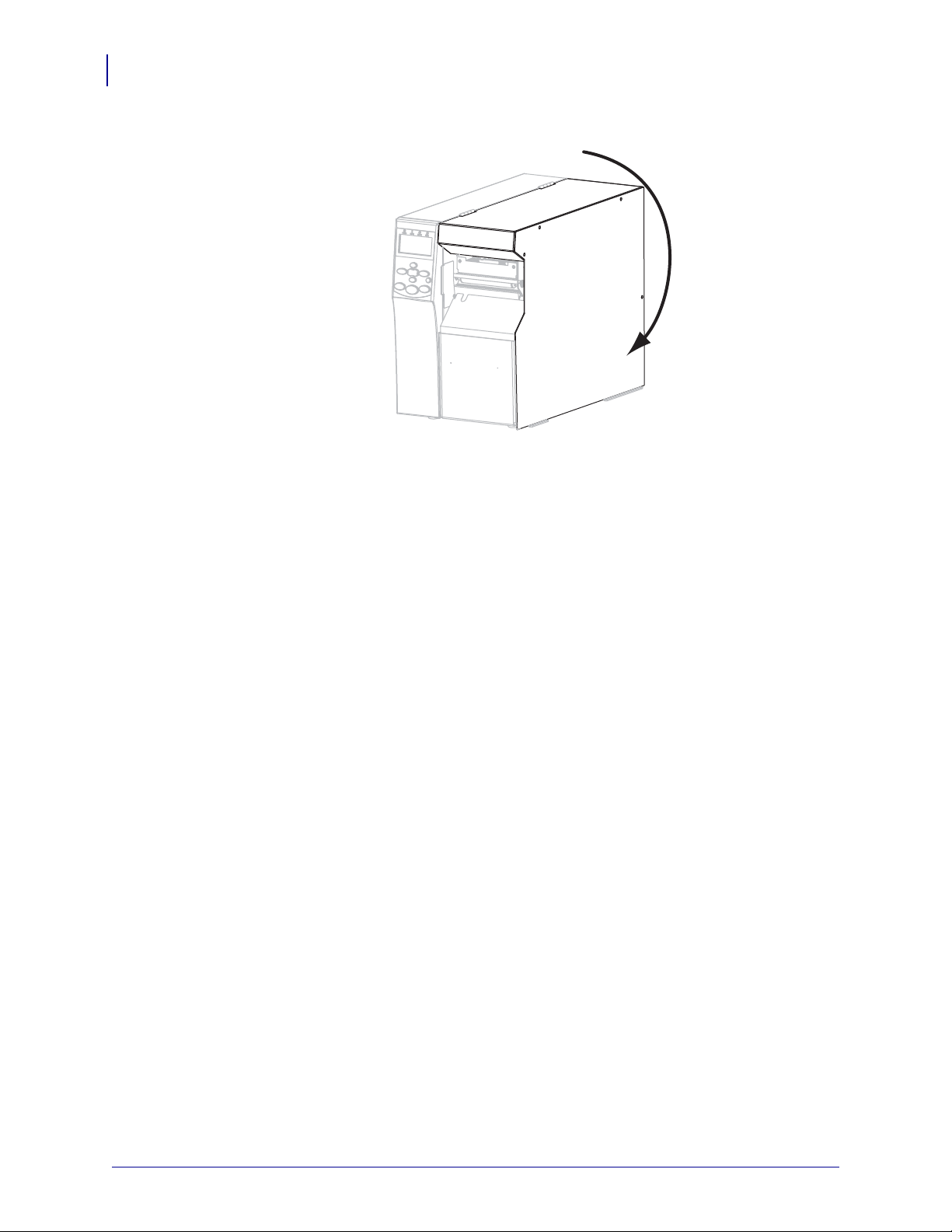
Printer Setup and Operation
76
Load the Media
20. Close the media door.
21. Set the printer to Rewind mode (for more information, see Print Mode on page 84).
22. If desired, perform the CANCEL Self Test on page 149 to verify that your printer is able to
print.
P1056468-001 11/6/12
Page 77

Printer Setup and Operation
1
2
3
1
2
Load the Media
Final Steps for Cutter Mode 7.
8.
Caution • The cutter blade is sharp. Do not touch or rub the blade with your fingers.
Thread the media forward until it passes under the printhead assembly (1), under the
snap plate (
2), and through the cutter assembly (3).
77
Align the media with the inner media guide (1). Slide in the outer media guide (2) until i t
9.
just touches the edge of the media.
11/6/12 P1056468-001
Page 78

Printer Setup and Operation
1
12
78
Load the Media
10. Tighten the thumb screw (not visible from this angle) that is located on the bottom of the
outer media guide (
11. Push down the printhead assembly (1), and then rotate the prin thead-open lever (2) unt il it
1).
locks into place.
The media winds on the rewind spindle or core.
P1056468-001 11/6/12
Page 79

Printer Setup and Operation
Load the Media
12. Close the media door.
13. Set the printer to Cutter mode (for more information, see Print Mode on page 84).
14. If desired, perform the CANCEL Self Test on page 149 to verify that your printer is able to
print.
79
11/6/12 P1056468-001
Page 80

Printer Setup and Operation
Notes • ___________________________________________________________________
__________________________________________________________________________
__________________________________________________________________________
__________________________________________________________________________
__________________________________________________________________________
__________________________________________________________________________
__________________________________________________________________________
__________________________________________________________________________
__________________________________________________________________________
__________________________________________________________________________
80
Load the Media
P1056468-001 11/6/12
Page 81

Printer Configuration
and Adjustment
This section assists you with configuration of and adjustments to the printer.
3
Contents
Changing Printer Settings . . . . . . . . . . . . . . . . . . . . . . . . . . . . . . . . . . . . . . . . . . . . . . . . 82
Print Settings . . . . . . . . . . . . . . . . . . . . . . . . . . . . . . . . . . . . . . . . . . . . . . . . . . . . . . . . 83
Maintenance and Diagnostic Tools . . . . . . . . . . . . . . . . . . . . . . . . . . . . . . . . . . . . . . . 89
Network Settings . . . . . . . . . . . . . . . . . . . . . . . . . . . . . . . . . . . . . . . . . . . . . . . . . . . . . 96
Language Settings. . . . . . . . . . . . . . . . . . . . . . . . . . . . . . . . . . . . . . . . . . . . . . . . . . . 100
Sensor Settings . . . . . . . . . . . . . . . . . . . . . . . . . . . . . . . . . . . . . . . . . . . . . . . . . . . . . 102
Port Settings . . . . . . . . . . . . . . . . . . . . . . . . . . . . . . . . . . . . . . . . . . . . . . . . . . . . . . . 103
Calibrate the Ribbon and Media Sensors Manually. . . . . . . . . . . . . . . . . . . . . . . . . . . . 106
Remove Used Ribbon . . . . . . . . . . . . . . . . . . . . . . . . . . . . . . . . . . . . . . . . . . . . . . . . . . 112
Remove Media or Liner from the Rewind Spindle . . . . . . . . . . . . . . . . . . . . . . . . . . . . . 113
Adjust Transmissive Media Sensors . . . . . . . . . . . . . . . . . . . . . . . . . . . . . . . . . . . . . . . 115
Upper Media Sensor . . . . . . . . . . . . . . . . . . . . . . . . . . . . . . . . . . . . . . . . . . . . . . . . . 115
Lower Media Sensor . . . . . . . . . . . . . . . . . . . . . . . . . . . . . . . . . . . . . . . . . . . . . . . . . 118
Adjust Printhead Pressure and Toggle Position. . . . . . . . . . . . . . . . . . . . . . . . . . . . . . . 119
Toggle Position Adjustment . . . . . . . . . . . . . . . . . . . . . . . . . . . . . . . . . . . . . . . . . . . . 119
Printhead Pressure Adjustment. . . . . . . . . . . . . . . . . . . . . . . . . . . . . . . . . . . . . . . . . 121
11/6/12 P1056468-001
Page 82

Printer Configuration and Adjustment
82
Changing Printer Settings
Changing Printer Settings
This section presents the printe r settings that you can change and identifies the tools for
changing them. These tools include the following:
• ZPL and Set/Get/Do (SGD) commands (See the Zebra
information.)
• T he printer’s control panel display (See Control Panel Display on page 17 for more
information.)
• T he printer’s web pages when the printer has an active wired or wireless print server
connection (See the ZebraNet Wired and Wireless Print Servers User Guide for more
information.)
Copies of the referenced manuals are available at http://www.zebra.com/manuals or on the
user CD that came with your printer.
This section contains the following subsections:
• Print Settings on page 83
• Maintenance and Diagnostic Tools on page 89
®
Programming Guide for more
• Network Settings on page 96
• Language Settings on page 100
• Port Settings on page 103
P1056468-001 11/6/12
Page 83

Print Settings
Table 7 • Print Settings
Printer Configuration and Adjustment
Changing Printer Settings
83
Print
Darkness
Set the darkness to the lowest setting that provid es good print quality. If you set the darkness
too high, the label image may print unclearly, bar codes may not scan correctly, the ribbon
may burn through, or the printhead may wear prematurely.
If desired, use the FEED Self Test on page 151 to determine the best darkness setting.
Accepted values:
Related ZPL command(s):
SGD command used:
0.0 – 30.0
^MD, ~SD
print.tone
Control panel menu item: DARKNESS on page 21
Printer web page:
View and Modify Printer Settings > General Setup >
Darkness
Print Speed Select the speed for printing a label (given in inches per second). Slower print speed s
typically yield better print quality.
Accepted values:
Related ZPL command(s):
SGD command used:
• 203 dpi: 2–12 ips
• 300 dpi: 2–9 ips
^PR
media.speed
Control panel menu item: PRINT SPEED on page 21
Printer web page:
View and Modify Printer Settings > General Setup >
Print Speed
11/6/12 P1056468-001
Page 84

Printer Configuration and Adjustment
1
2
1
Media direction
2
Factory-set tear line location at position 000
84
Changing Printer Settings
Table 7 • Print Settings (Continued)
Tear-Off
Position
If necessary, adjust the position of the media over the tear-off bar after printing.
• Higher numbers move the media out (the tear line moves closer to the leading edge of
the next label).
• Lower numbers move the media in (the tear line moves closer to the edge of the label
just printed).
Accepted values:
Related ZPL command(s):
–120 to 120
~TA
SGD command used:
none
Control panel menu item: TEAR OFF on page 21
Printer web page:
View and Modify Printer Settings > General Setup >
Tear Off
Print Mode Select a print mode that is compatible with your printer options.
Accepted values:
• TEAR OFF—The printer prints label formats as it
receives them. The printer operator can tear off the
printed labels any time after they print.
• PEEL—The printer peels the label from the liner
during printing and then pauses until the label is
removed. The liner winds onto the rewind spindle.
• REWIND—The printer prints without pausing
between labels. The media is wound onto the rewind
spindle after printing.
• CUTTER—The printer prints a label and then cuts it
free.
Related ZPL command(s):
SGD command used:
Control panel menu item: PRINT MODE on page 21
Printer web page:
^MM
media.printmode
View and Modify Printer Settings > General Setup >
Print Mode
P1056468-001 11/6/12
Page 85

Table 7 • Print Settings (Continued)
Media Type Select the type of media that you are using.
• If you select CONTINUOUS, you must include a label length in your label format (^LL
if you are using ZPL).
• If you select NON-CONTINUOUS for various non-continuous media, the printer feeds
media to calculate the label length.
See Types of Media on page 47 for more information.
Printer Configuration and Adjustment
Changing Printer Settings
85
Accepted values:
Related ZPL command(s):
SGD command used:
• CONTINUOUS
• NON-CONTINUOUS
^MN
none
Control panel menu item: MEDIA TYPE on page 22
Printer web page:
View and Modify Printer Settings > Media Setup >
Media Type
Print Method Specify if ribbon is being used. Thermal Transfer media requires ribbon for printing while
Direct Thermal media does not.
To determine if you need to use ribbon, see When to Use Ribbon on page 49.
Accepted values:
Related ZPL command(s):
SGD command used:
• THERMAL TRANS
• DIRECT THERMAL
^MT
none
Control panel menu item: PRINT METHOD on page 22
Printer web page:
View and Modify Printer Settings > Media Setup >
Print Method
Print Width Specify the width of the labels being used.
Note • Setting the width too narrow can result in portions of a label format not being
printed on the media. Setting the width too wide waste s formatti ng memory and can
cause the printer to print off of the label and onto the platen roller. This setting can
affect the horizontal position of the label format if the image was inverted using the
^POI ZPL II command.
Accepted values:
minimum: 2 dots
maximum:
• 203 dpi: 832 dots
• 300 dpi: 1248 dots
Related ZPL command(s):
SGD command used:
^PW
none
Control panel menu item: PRINT WIDTH on page 22
Printer web page:
11/6/12 P1056468-001
View and Modify Printer Settings > Media Setup >
Print Width
Page 86

Printer Configuration and Adjustment
2
1
Label length (including interlabel gap)
2
Interlabel gap
3
Set the maximum label length to approximately
this value
1
3
86
Changing Printer Settings
Table 7 • Print Settings (Continued)
Maximum
Label Length
Set the maximum label length to a value that is at least 1.0 in. (25.4 mm) greater than the
actual label length plus the inte rl ab el gap . If you set the value to one that is smaller t ha n the
label length, the printer assumes tha t continuous media is loaded, and the printer cannot
calibrate.
For example, if the label length is 6.0 inches (152 mm) including the interlabel gap, set the
parameter for at least 7.0 inches (178 mm).
Related ZPL command(s): ^ML
Control panel menu item:
P1056468-001 11/6/12
Accepted values:
SGD command used:
Printer web page:
0 to the maximum label length supported by the printer
none
MAXIMUM LENGTH on page 22
View and Modify Printer Settings > Media Setup >
Maximum Length
Page 87

Printer Configuration and Adjustment
Table 7 • Print Settings (Continued)
Changing Printer Settings
87
Backfeed
Sequence
Label Top
Position
This parameter sets when label backfeed occurs after a label is removed in some print
modes. It has no effect in Rewind mode. This setting is superseded by
~JS when received
as part of a label format.
Accepted values:
• AFTER (backfeed occurs immediately after the last
label is completed)
• OFF (no backfeed)
• BEFORE (backfeed occurs before the forward motion
of the first label)
• DEFAULT
Related ZPL command(s): ~JS
SGD command used:
none
Control panel menu item: BACKFEED on page 30
Printer web page:
View and Modify Printer Settings > Advanced Setup >
Backfeed
This parameter adjusts the print positio n vertically on the label. Positive n umb ers ad ju st the
label top position farther down the lab el (a way from t he prin th ead ) by t he spec ified n umber
of dots. Negative numbers adjust the position up the label (toward the printhead).
Accepted values:
–120 to 120
Related ZPL command(s): ^LT
Label Left
Position
Head Test
Count
SGD command used:
none
Control panel menu item: LABEL TOP on page 30
Printer web page:
View and Modify Printer Settings > General Setup >
Label Top
If necessary , shift the print position horizontally on t he label. Positive numbe rs move the left
edge of the image toward the center of the label by the number of dots selected, while
negative numbers move the left edge of the image toward the left edge of the label.
Accepted values:
–9999 to 9999
Related ZPL command(s): ^LS
SGD command used:
none
Control panel menu item: LEFT POSITION on page 30
Printer web page:
View and Modify Printer Settings > Advanced Setup >
Left Position
The printer periodically performs a test of the printhead functionality. This parameter
establishes how many labels are printed between these internal tests.
Accepted values:
0000 (disables the test) to 9999
Related ZPL command(s): ^JT
SGD command used:
none
Control panel menu item: HEAD TEST COUNT on page 30
Printer web page:
11/6/12 P1056468-001
View and Modify Printer Settings > Advanced Setup >
Head Test Count
Page 88

Printer Configuration and Adjustment
88
Changing Printer Settings
Table 7 • Print Settings (Continued)
Reprint
Mode
When reprint mode is enabled, you can reprint the last label printed by pressin g and holdin g
PAUSE + CANCEL on the printer’s control panel.
Accepted values:
• ON
• OFF
Related ZPL command(s): ^JZ
SGD command used:
none
Control panel menu item: REPRINT MODE on page 31
Printer web page: N/A
P1056468-001 11/6/12
Page 89

Maintenance and Diagnostic Tools
Table 8 • Maintenance and Diagnostic Tools
Printer Configuration and Adjustment
Changing Printer Settings
89
Supplies Low
Warning
Early Warning
for Maintenance
Printhead
Cleaning Interval
When this feature is enabled, the printer provides warnings when the media or ribbon is
reaching near the end of the roll.
Accepted values:
Related ZPL command(s):
SGD command used:
MEDIA DISABLED, MEDIA ENABLED
^JH
none
Control panel menu item: SUPPLIES WARNING on page 23
Printer web page:
View and Modify Printer Settings > General Setup
> Early Warning (Media)
When this feature is enabled, the printer provides wa rnings when the p rinthead nee ds to
be cleaned.
Accepted values:
Related ZPL command(s):
SGD command used:
MAINT. OFF, MAINT. ON
^JH
none
Control panel menu item: EARLY WARNING MAINTENANCE on page 23
Printer web page:
View and Modify Printer Settings > General Setup
> Early Warning (Maintenance)
When Early Warning for Maintenance is enabled, set this value to the length of the
media or ribbon roll that you are using.
When the printhead reaches the set length,
WARNING CLEAN PRINTHEAD appears on
the control panel display. If the alert function is enabled, the printer generates an alert.
Printhead Life
Expectancy
Accepted values:
Related ZPL command(s):
SGD command used:
0 M/0 FT to 450M/1476 FT in 50 M increments
^JH
none
Control panel menu item: HEAD CLEANING on page 23
Printer web page:
View and Modify Printer Settings > General Setup
> Head Cleaning
When Early Warning for Maintenance is enabled, set this value to the number of inches
of media that the printhead is expected to print.
When the printhead reaches the set length,
WARNING REPLACE HEAD appears on the
control panel display. If the alert function is enabled, the printer generates an alert.
Accepted values:
Related ZPL command(s):
SGD command used:
0 M/0 FT to 450M/1476 FT in 50 M increments
^JH
none
Control panel menu item: HEAD LIFE on page 23
Printer web page:
View and Modify Printer Settings > General Setup
> Head Life
11/6/12 P1056468-001
Page 90

Printer Configuration and Adjustment
90
Changing Printer Settings
Table 8 • Maintenance and Diagnostic Tools (Continued)
Non-Resettable
Counter
User-Controlled
Counters
Print Counter
Readings
The non-resettable counter gives the total length of media that the printer has printed.
You can use firmware commands to change the unit of measure for this counter.
Related ZPL command(s):
SGD command used:
^MA (for changing unit of measure)
none
Control panel menu item: NONRESET CNTR on page 24
Printer web page:
none
Two user-controlled counters give the tot al len gt h of media that the printe r has prin ted
since the last time the counter was reset. You can use firmware commands to change the
unit of measure and reset the counters.
Related ZPL command(s):
^MA (for changing unit of measure)
~RO (for resetting counters)
SGD command used:
odometer.media_marker_count1
odometer.media_marker_count2
Control panel menu item: RESET CNTR1 on page 24
RESET CNTR2 on page 24
Printer web page:
none
Prints a label that lists the odometer readings for the following:
• the non-resettable counter
• the two user-controlled counters
• the Early Warning for Maintenance counters, which indicate when the printhead
was last cleaned and the printhead life (If the Early Warning for Maintenance
feature is disabled, the counters related to it do not print.)
Related ZPL command(s):
SGD command used:
Control panel menu item:
Printer web page:
~HQ
none
PRINT METERS on page 24
none
P1056468-001 11/6/12
Page 91

Printer Configuration and Adjustment
Changing Printer Settings
Table 8 • Maintenance and Diagnostic Tools (Continued)
91
Print
Information
Print the specified information on one or more labels.
• FONTS—Prints the available fonts in the printer, including standard printer fonts
plus any optional fonts. Fonts may be stored in RAM or Flash memory.
• BAR CODES—Prints the available bar codes in the printer. Bar codes may be stored
in RAM or Flash memory.
• IMAGES—Prints the available images stored in the printer’s RAM, Flash memory,
or optional memory card.
• FORMATS—Prints the available formats stored in the printer’s RAM, Flash
memory, or optional memory card.
• SETUP—Prints the printer configuration label.
• NETWORK—Prints the settings for any print server that is installed.
• ALL—Prints the previous six labels.
Related ZPL command(s):
Printer configuration: ~WC
Network: ~WL
Others: ^WD
SGD command used: none
Control panel menu item:
LIST FONTS on page 25
LIST BAR CODES on page 25
LIST IMAGES on page 25
LIST FORMATS on page 25
LIST SETUP on page 25
LIST NETWORK on page 26
LIST ALL on page 26
Print a Sensor
Profile
Initialize Flash
Memory
Printer web page:
View and Modify Printer Settings >
Print Listings on Label
Shows the sensor settings compared to actual sensor readings.
To interpret the results of the sensor profile, see Sensor Profile on page 156.
Related ZPL command(s):
~JG
SGD command used: none
Control panel menu item:
Printer web page:
SENSOR PROFILE on page 26
View and Modify Printer Settings >
Print Listings on Label
This option erases all previously stored information from Flash memory.
Caution • This option completely erases the Flash memory.
Related ZPL command(s):
^JB
SGD command used: none
Control panel menu item:
Printer web page:
INIT FLASH MEM. on page 26
View and Modify Printer Settings > Advanced
Setup > Format Memory
11/6/12 P1056468-001
Page 92

Printer Configuration and Adjustment
92
Changing Printer Settings
Table 8 • Maintenance and Diagnostic Tools (Continued)
Power-Up Action Set the Power-Up Action
Set the action for the printer to take during the power-up sequence.
• CALIBRATE adjusts sensor levels and thresholds, determines the lab el length, an d
feeds the media to the next web.
• FEED—feeds the labels to the first registration point.
• LENGTH determines the label length using current sensor values, and feeds the
media to the next web.
• NO MOTION tells the printer not to move the media. You must manually ensure
that the web is positioned correctly, or press feed to position the next web.
• SHORT CAL sets the media and web thresholds without adjusting sensor gain,
determines the label length, and fee ds the media to the next web.
Head-Close
Action
Accepted values:
Related ZPL command(s):
SGD command used:
• CALIBRATE
• FEED
• LENGTH
• NO MOTION
• SHORT CAL
^MF
none
Control panel menu item: MEDIA POWER UP on page 29
Printer web page:
View and Modify Printer Settings > Calibration
Set the Head-Close Action
Set the action for the printer to take when you close the printhead.
• CALIBRATE adjusts sensor levels and thresholds, determines the lab el length, an d
feeds the media to the next web.
• FEED—feeds the labels to the first registration point.
• LENGTH determines the label length using current sensor values, and feeds the
media to the next web.
• NO MOTION tells the printer not to move the media. You must manually ensure
that the web is positioned correctly, or press feed to position the next web.
• SHORT CAL sets the media and web thresholds without adjusting sensor gain,
determines the label length, and fee ds the media to the next web.
Accepted values:
Related ZPL command(s):
SGD command used:
• CALIBRATE
• FEED
• LENGTH
• NO MOTION
• SHORT CAL
^MF
none
Control panel menu item: HEAD CLOSE on page 30
Printer web page:
P1056468-001 11/6/12
View and Modify Printer Settings > Calibration
Page 93

Table 8 • Maintenance and Diagnostic Tools (Continued)
Load Defaults Load Printer or Print Server Defaults
• F ACT ORY—Restores all printer settings other than the network settings back to the
factory defaults. Use care when loading defaults because you will need to reload all
settings that you changed manually.
• NETWORK—Reinitializes the printer’s wired or wireless print server. With a
wireless print server, the printer will also reassociate with your wireless network.
• LAST SAVED—Loads settings from the last permanent save.
Printer Configuration and Adjustment
Changing Printer Settings
93
Accepted values:
Related ZPL command(s):
SGD command used:
Control panel menu item:
Control panel key(s):
Printer web page:
• FACTORY
• NETWORK
• LAST SAVED
Factory: ^JUF
Network: ^JUN
Last saved: ^JUR
none
Available as options when exiting Setup Mode. See
Exit Setup Mode on page 19.
Factory: Hold FEED + PAUSE during printer
power-up to reset the printer paramete rs to fa cto r y
values.
Network: Hold CANCEL + PAUSE during printer
power-up to reset the network parameters to factor y
values.
Last saved: N/A
Factory: View and Modify Printer Settings >
Restore Default Configuration
Network: Print Server Settings > Reset Print
Server
Last saved: View and Modify Printer Settings >
Restore Saved Configuration
11/6/12 P1056468-001
Page 94

Printer Configuration and Adjustment
94
Changing Printer Settings
Table 8 • Maintenance and Diagnostic Tools (Continued)
Media and
Ribbon Sensor
Calibration
Communication
Diagnostics Mode
Calibrate the printer to adjust the sensitivity of the media and ribbon sensors.
For complete instructions on how to perform a calibration procedure, see Calibrate the
Ribbon and Media Sensors Manually on page 106.
Accepted values:
Related ZPL command(s):
SGD command used:
Control panel menu item:
Control panel key(s):
N/A
~JC
none
MEDIA AND RIBBON CALIBRATE on page 27
Hold PAUSE + FEED + CANCEL for 2 seconds to
initiate calibration.
Printer web page:
The calibration procedure cannot be initiated through
the web pages. See the following web page for
settings that are set during sensor calibration:
View and Modify Printer Settings > Calibration
Important •
Do not change these settings
unless you are told to do so by Zebra
T echnical Support or by an authorized service
technician.
Use this diagnostics tool to cause the printer to output the hexadecimal values for all
data received by the printer.
For more information, see Communication Diagnostics Test on page 155.
Format
Conversion
Accepted values:
Related ZPL command(s):
SGD command used:
Control panel menu item:
• DISABLED
• ENABLED
~JD to enable, ~JE to disable
none
COMMUNICATIONS on page 28
Printer web page: N/A
Selects the bitmap scaling factor. The first number is the original dots per inch (dpi)
value; the second, the dpi to which you would like to scale.
Accepted values:
• NONE
• 150 → 300
• 150 → 600
• 200 → 600
• 300 → 600
Related ZPL command(s): none
SGD command used: none
Control panel menu item: FORMAT CONVERT on page 31
Printer web page: none
P1056468-001 11/6/12
Page 95

Printer Configuration and Adjustment
Changing Printer Settings
Table 8 • Maintenance and Diagnostic Tools (Continued)
Idle Display Select the information shown on the printer’s display when the printer is idle.
95
Accepted values:
• FIRMWARE (FW) VERSION
• MM/DD/YY 24 HR
• M/DD/YY 12 HR
• DD/MM/YY 24 HR
• DD/MM/YY 12 HR
Related ZPL command(s): none
SGD command used:
none
Control panel menu item: IDLE DISPLAY on page 32
Printer web page: N/A
RTC Date This parameter allows you to set the date to display in the Idle Display.
Related ZPL command(s): ^ST
SGD command used: none
Control panel menu item: RTC DATE on page 32
Printer web page: none
RTC Time This parameter allows you to set the time to display in the Idle Display.
Related ZPL command(s): ^ST
SGD command used: none
Control panel menu item: RTC TIME on page 32
Printer web page: none
Password Level This parameter allows you to select whether certain factory-selected menu items or all
menu items are password protected.
Accepted values:
• SELECTED ITEMS
• ALL ITEMS
Related ZPL command(s): none
SGD command used: none
Control panel menu item: PASSWORD LEVEL on page 35
Printer web page: none
Run a ZBI
Program
If you have ZBI 2.0 installed, you may choose to run a ZBI program that you have
downloaded to your printer.
Accepted values:
Related ZPL command(s):
SGD command used:
Control panel menu item:
Printer web page:
N/A
^JI, ~JI
zbi.control.run
Run the Specified ZBI Program* on page 32
Directory Listing
11/6/12 P1056468-001
Page 96

Printer Configuration and Adjustment
96
Changing Printer Settings
Network Settings
Table 9 • Network Settings
Primary Network Select the Primary Network Device
This parameter determines which device should be considered primary in the active
device selection.
Load from
External Device
Active Print
Server
Accepted values:
Related ZPL command(s):
• WIRED
• WIRELESS
^NC
SGD command used: ip.primary_network
Control panel menu item: PRIMARY NETWORK on page 32
Printer web page: none
View if IP Settings Are Loaded from the Printer or Print Server
This parameter tells whether to use the printer’s or the print server’s LAN/WLAN
settings at power-up. The default is to use the printer’s settings.
Accepted values:
Related ZPL command(s):
• YES
• NO
^NP
SGD command used: none
Control panel menu item: LOAD FROM EXT? on page 33
Printer web page: none
View the Active Print Server
This menu item displays which print server is being used. This tells which device’s
settings such as IP protocol and IP address are being displayed under tho se menu items.
Accepted values:
• WIRELESS indicates that the wireless print server
is active.
• INTERNAL WIRED indicates that the internal
wired print server is active.
• EXTERNAL WIRED indicates that an external
wired print server is active.
• NONE indicates that one of the network options is
installed but is not active. When NONE is shown
for this menu item, the device-specific items such
as IP protocol and IP address will not display.
Related ZPL command(s): none
SGD command used: none
Control panel menu item: ACTIVE PRINTSRVR on page 33
Printer web page: none
P1056468-001 11/6/12
Page 97

Table 9 • Network Settings (Continued)
IP Protocol Set the IP Resolution Method
This parameter tells if the user (permanent) or the server (dynamic) selects the
IP address. If a dynamic option is chosen, this parameter tells the method(s) by which
the wired or wireless print server receives the IP address from the server.
Printer Configuration and Adjustment
Changing Printer Settings
97
Accepted values:
Related ZPL command(s):
• ALL
• GLEANING ONLY
• RARP
• BOOTP
• DHCP
• DHCP & BOOTP
• PERMANENT
^ND
SGD command used: Wired: internal_wired.ip.protocol
Wireless: wlan.ip.protocol
Control panel menu item: IP PROTOCOL on page 33
Printer web page:
View and Modify Printer Settings >
IP Address View or Set the Printer’s IP Address
View and, if necessary, change the printer’s IP address.
Changes to this setting are saved only if IP PROTOCOL is set to PERMANENT. To
allow any saved changes to take effect, reset the print server (see Reset Network
on page 99).
external_wired.ip.protocol
Network Communications Setup >
TCP/IP Settings > IP Protocol
Accepted values:
Related ZPL command(s):
000 to 255 for each field
^ND
SGD command used: Wired: internal_wired.ip.addr
external_wired.ip.addr
Wireless: ip.addr, wlan.ip.addr
Control panel menu item: IP ADDRESS on page 33
Printer web page:
View and Modify Printer Settings >
Network Communications Setup >
TCP/IP Settings > IP Address
11/6/12 P1056468-001
Page 98

Printer Configuration and Adjustment
98
Changing Printer Settings
Table 9 • Network Settings (Continued)
Subnet Mask View or Set the Subnet Mask
View and, if necessary, change the subnet mask.
This menu item appears only if a wired or wireless print server is installed on yo ur
printer. To save changes to this setting, set
reset the print server (see Reset Network on page 99).
IP PROTOCOL to PERMANENT, and then
Accepted values:
Related ZPL command(s):
SGD command used: Wired: internal_wired.ip.netmask
Control panel menu item: SUBNET MASK on page 34
Printer web page:
Default Gateway View or Set the Default Gateway
View and, if necessary, change the default gateway.
This menu item appears only if a wired or wireless print server is installed on yo ur
printer. To save changes to this setting, set
reset the print server (see Reset Network on page 99).
Accepted values:
Related ZPL command(s):
SGD command used: Wired: internal_wired.ip.gateway
000 to 255 for each field
^ND
external_wired.ip.netmask
Wireless: wlan.ip.netmask
View and Modify Printer Settings >
Network Communications Setup >
TCP/IP Settings > Subnet Mask
IP PROTOCOL to PERMANENT, and then
000 to 255 for each field
^ND
external_wired.ip.gateway
Wireless: wlan.ip.gateway
Control panel menu item: DEFAULT GATEWAY on page 34
Printer web page:
View and Modify Printer Settings >
Network Communications Setup >
TCP/IP Settings > Default Gateway
MAC Address View the MAC Address
V iew the Media Access Control (MAC) address of the print server that i s installed in the
printer (wired or wireless).
Accepted values:
Related ZPL command(s):
N/A
none
SGD command used: Wired: internal_wired.mac_addr
external_wired.mac_addr
Wireless: wlan.mac_addr
Control panel menu item: MAC ADDRESS on page 34
Printer web page: none
P1056468-001 11/6/12
Page 99

Table 9 • Network Settings (Continued)
ESSID View the ESSID Value
The Extended Service Set Identification (ESSID) is an identifier for your wireless
network. This setting, which cannot be modified from the control pa nel, gives the
ESSID for the current wireless configuration.
Printer Configuration and Adjustment
Changing Printer Settings
99
Accepted values:
Related ZPL command(s):
32-character alphanumeric string (default 125)
none
SGD command used: wlan.essid
Control panel menu item: ESSID on page 34
Printer web page: none
Reset Network This option resets the wired or wireless print server. You must reset the print serv er to
allow any changes to the network settings to take effect.
Accepted values:
Related ZPL command(s):
SGD command used:
N/A
~WR
device.reset
Control panel menu item: RESET NETWORK on page 35
Printer web page:
Print Server Settings >
Factory Print Server Settings
11/6/12 P1056468-001
Page 100

100
Printer Configuration and Adjustment
Changing Printer Settings
Language Settings
Table 10 • Language Settings
Language If necessary, change the language that the printer displays.
This change affects the words shown on the following:
• status and error messages
• the printer parameters
• the printer configuration label, the network configurat ion label, and ot her labels that you
can select to print through the user menus (This does not apply to Japanese, Korean,
Simplified Chinese, or Traditional Chinese. Labels for those languages print in English.)
Note • The selections for this parameter are displayed in the actual languages to
make it easier for you to find one that you are able to read.
Control
Character
Accepted values:
ENGLISH, SPANISH, FRENCH, GERMAN, ITALIAN,
NORWEGIAN, PORTUGUESE, SWEDISH, DANISH,
SPANISH 2, DUTCH, FINNISH, JAP ANESE,
KOREAN, SIMPLIFIED CHINESE, TRADITIONAL
CHINESE, RUSSIAN, POLISH, CZECH, ROMANIAN
Related ZPL command(s): ^KL
SGD command used:
Control panel menu item:
Printer web page:
none
LANGUAGE on page 36
View and Modify Printer Settings > General Setup >
Language
Set the Control Prefix Character Value
The printer looks for this two-digit hex character to indicate the start of a ZPL/ZPL II
control instruction.
Set the control prefix character to match what is used in your label formats.
Accepted values: 00 to FF
Related ZPL command(s): ^CT or ~CT
SGD command used:
none
Control panel menu item: CONTROL PREFIX on page 29
Printer web page:
View and Modify Printer Settings > ZPL Control
P1056468-001 11/6/12
 Loading...