

Page 1

i
P/N: MUL-53249-01
Page 2
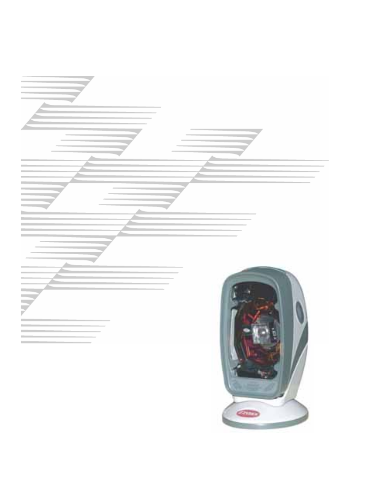
User ' s Manual
Z-6070 Series Hand Free
Laser Scanner
i
Page 3

Importance
This equipment generates, uses and can radiate radio frequency
energy. If not installed and used in accordance with the instructions
in this manual, it may cause interference to radio communications.
The equipment has been tested and found to comply with the limits
for a Class A computing device pursuant to EN55022 and 47
CFR,part2 and Part 15 of FCC Rules. These specifications are
designed to provide reasonable protection against interference when
operated in a commercial environment.
For CE-countries:
- The Z-6070 is in conformity with the CE standards. Please note
that a ZEBEX CE-Marked power supply unit should be used to
conform to these standards.
Radio and television interference
Operation of this equipment in a residential area can cause
interference to radio or television reception. This can be determined
by turning the equipment off and on. The user is encouraged to try
to correct the interference by one or more of the following measures:
Re-orientate the receiving antenna
Relocate the device with respect to the receiver
Move the device away from the receiver
Plug the device into a different outlet so that the
device and the receiver are on different branch
circuits
If necessary, the user should consult the manufacturer, an authorized
dealer or experienced radio/television technician for additional
suggestion. The user may find the following booklet prepared by the
Federal Communications Commission helpful:
“How to ldentify and Resolve Radio-TV Interference Problems”.
This booklet is available from the U.S. Government Printing Office,
Washington, DC 20402, Stock No. 004000003454.
i
Page 4

Important Notice
ZEBEX INDUSTRIES INC. MAKES NO WARRANTY OF
ANY KIND WITH REGARD TO THIS MATERIAL,
INCLUDING, BUT NOT LIMITED TO, THE IMPLIED
WARRANTIES OF MERCHANT ABILITY AND FITNESS
FOR A PARTICULAR PROPOSE. ZEBEX INDUSTRIES
INC. SHALL NOT BE LIABLE FOR ERRORS CONTAINED
HEREIN OF FOR INCIDENTAL CONSEQUENTIAL
DAMAGES IN CONNECTION WITH THE FURISHING,
PERFORMANCE, OR USE OF THESE MATERIALS.
Copyright 2004 by
ZEBEX INDUSTRIES INC.
All other registered trademarks are registered companies’
property. ZEBEX is a registered trademark of ZEBEX
INDUSTRIES INC.
All rights reserved, reproduction of this document or any
portion of its contents is not allowed without the specific
written consent of ZEBEX INDUSTRIES INC.
Printed In May, 2004
ii
Page 5

TABLE OF CONTENTS
Introduction ......................................................................... 1
Unpacking...........................................................................2
Scanner Outline and Indicator............................................. 4
Power Connection............................................................... 6
Verify the Scanning Operation............................................. 7
Template Installation (if required) ........................................ 8
Connecting the Scanner.................................................... 10
RS-232 interface...................................................... 10
Keyboard wedge.......................................................11
USB Interface.......................................................... 12
Wand emulation....................................................... 13
Replacing the Interface Cable........................................... 14
How to Scan...................................................................... 15
Scanning Operation
Multi-line mode ........................................................ 15
Fixed mode scanning..................................... 16
Hand held mode............................................. 18
Single line mode...................................................... 19
Sleep Mode....................................................................... 20
LED & Beeper Indications................................................. 21
Changing Beeper Volume Using Push Button................... 23
Maintaining the Scanner.................................................... 24
Controlling Scanner from the POS System....................... 25
Laser Safety...................................................................... 26
Appendixes
Appendix A: Connector & Pin Out............................ 29
Appendix B: Specifications ...................................... 30
Appendix C: Trouble Shooting................................. 32
iii
Page 6

Introduction
Z-6070 is the first dual-laser presentation scanner in the
world with numerous record-breaking key features. Its
pioneered application of dual laser diodes drastically
enhance scanning power by doubling up scan lines,
broadening scan angle and intensifying scan pattern across
scan field. With this state-of-art technology, Z-6070 is able to
deliver the most comprehensive 32-line sca n pattern
empowering 2400 scans per second, In addition, Z-6070 is
equipped with Z-SCAN technology, which is an in novative
ASIC hardware decode technology to provide real-time
decode capability to effectively shorten customer transaction
time.
Z-6070’s broad scan field could effectively facilitate sca nning
barcodes on products in all kinds of shapes. Moreover, it is
designed for both hands-free and handheld applications. To
scan large merchandise that cannot be placed on the counter,
sales clerks could easily pick up Z-6070 from its stand to
perform the product scan. While scanning multiple barcod es
on one object, sales clerks could switch it to single line sca n
option simply by pressing one button. The adjustable stand
design grants users the flexibility to set the easiest angle of
scan. Furthermore, Z-6070 is programmed with multiple
beeper tones and barcode data edition function for different
applications.
1
Page 7
Unpacking
When you open the Z-6070 c ontaining box, please check to
make sure everything you ordered is present and check if
there is any damage during shipment. If you find any
damages or missing components, please re port immediately
to your sales representative.
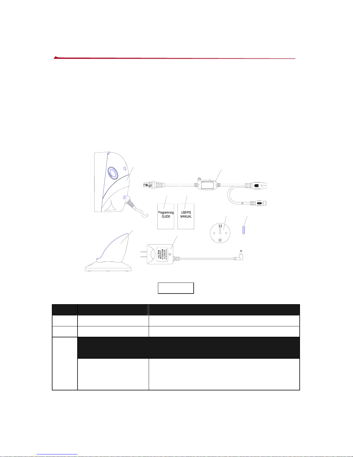
Open the box, in it should contain:
A
B
C
D
E
F
G G
Figure 1
Item Part n. Description
A Z67-93390-US Z-6070 hand free scanner
B Z67-93390-US Adjustable stand (optional)
Communication and power link Cable (Accordin g to
order)
C
CAB-53122-DM
+
CAB-50114-CA
Keyboard wedge cable for
PC/AT/PS2
2
Page 8
3
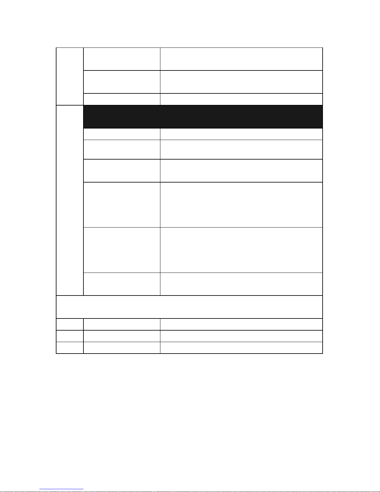
CAB-53129-RP
DB-9 female connector RS232 cable
DTE pin-out
CAB-53130-R9
DB-9 female connector RS232 cable
DCE pin-out
CAB-53131-UB Low speed USB cable
AC to DC power adaptor---Regulate 5V@600mA
(Optional by order)
PWO-90810-US 120V United States
PWO-90811-EU 230V Continental European
PWO-52215-US
100~240V United States,Applied
Regions:North America, Japan
PWO-52212-EU
100~240V Continental European
Applied Regions:
Europe, Middle East, South
East,Asia, South America
PWO-52213-UK
100~240V United Kingdom Applied
Regions:
Hong Kong, Malaysia, Singapore,
UAE, UK
D
PWO-52214-AU
100~240V Applied Regions:New
Zealand, Australia
For special power requirement, please contact your dealer,
distributor or directly contact ZEBEX
E MUL-53249-xx Reference manual
F MUL-53243-xx Programming Guide
G MET-01531-FP base template /Screw(optional)
Page 9
Scanner Outline and Indicator
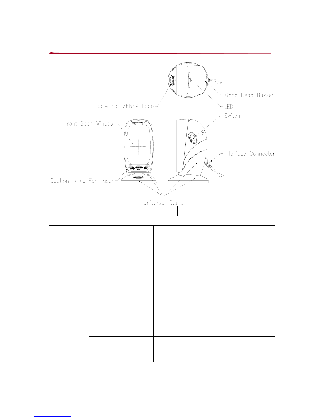
Figure 2
Wake up scanner When the scanner enters into the
sleep mode, pressing this switch can
wake the scanner up. The sleep
mode feature can be programmed
using the menu labels from the
Programming Guide.
NOTE: The default value for the
sleep mode time-out is set to 10
minutes after laser sleep, 30
minutes after motor sleep. When
the scanner is in sleep mode, the
LED is intermittently flashing red.
Button
Single -line pattern Pick up the scanner, press and
release the trigger will active single
line scan mode
4
Page 10
5
Beeper tone
selection
When the scanner is sitting in the
adjustable stand, press down this
button for a duration of time (5 sec),
it will automatically change the
beeper volume.
LED
A red LED indicates the scanner is ready to read a
barcode while a green LED indicates a good read.
Good
Read
Buzzer
If the data is captured correctly, the buzzer will be heard.
Both the volume and frequency are programmable using
the menu labels from the Programming Guide.
Adjustable
stand
This stand allows you to direct the scan pattern in a way
that is the best for your application by adjusting the
scanner window forward, backward.
Power
Link
interface
cable
Connect the external AC/DC power adaptor into
the power jack on the power link cable. And the
interface connector provides the communication
the scanner and host terminal
Page 11

Power Connection
The interface cable can support direct power or externa l
power to scanner . If external power has been inserted to the
cable power jack, it will automatically switching off the direct
power from host to scanner.
If your host does not provide power to the scanner, you will
need an external power connection to the scanner:
1. Connect the interface cable to the bottom of the
scanner, as described in How to connect the
scanner.
2. Connect the other end of the interface cable to the
host (refer to your host manual to locate for correct
port).
3. Plug the power supply into the power jack on the
interface cable.
4. Plug the other end of the power supply into an AC
outlet.
Note:
1. Although, the Z-6070 can use direct power from host
device, but if the Host (computer) doesn’t provide
sufficient current for scanner, sometimes it will cause
interference and affects the scanner or PC, this is also
the reason why a scanner could work more sufficiently
on a computer but not others.
2. The host system should be capable to supply a minimum
of 300mA of current @ 5VDC.
3. In order to obtain the best steady operation, ZEBEX
recommends using the external power supply provided
with the Z-6070 when connect to keyboard wedge or
USB host.
6
Page 12

Verify the Scanning Operation
Before installing your Z-6070 scanner, please follow the
procedures below. This will lead to proceed for scannin g
properly.
1. Connect the modular plug of the power link cable into the
back of the scanner.
2. Plug the DC plug of the power adaptor into the jack on
the power link cable.
3. Plug the AC end of the power adaptor into an AC outlet.
4. When the scanner powers up, LED lights in green and
the buzzer sound with 3-string-long-beep sound. When
the self-test is completed the LED status will return red.
5. Present the “test barcode” below to the scanner. If the
scanner is functioning properly, it will issue a short beep
and a green LED indicates a good rea d than remove the
“test barcode”
.
Note:
(1) If the scanner does not perform any or correct beep
sound, or without any LED indication when powers-up,
powers down the scanner and refer to Appendix B for
troubleshooting.
(2) If the initial interface of the scanner is in keyboard wedge,
and it only reads one barcode and remains with a green
LED indicating light, this is because the scanner is not
connected to a host terminal.
7
Page 13
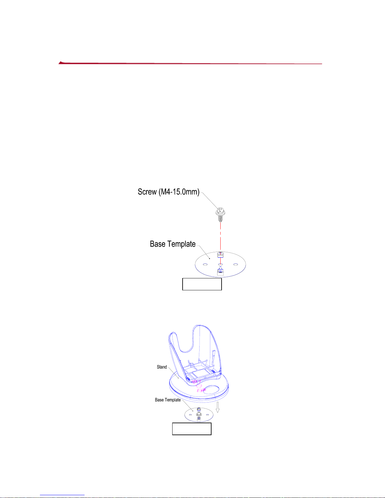
Template installation (if required)
The adjustable stand has non-skid rubber feet on the bottom
to prevent unnecessary slippery occurred, but for some
special application, it may need to be kept fixed permanently
on the counter top.
The base template can be mounted on a flat counter top.
1. Put the template at where you want to fix the stand.
2. Screw down to mount the template onto the counter.
(Use M4 or screws with header outer diameter not over
8.5mm are recommended.)
Figure 3
3. Align the hole on the bottom of the stand (show as in dot
lines), and clip onto the template.
Figure 4
8
Page 14
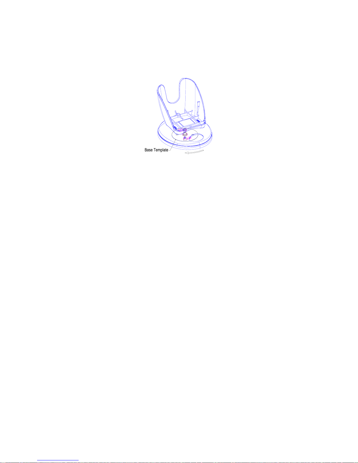
4. Turn the stand about 30° clockwise to properly clip the
stand onto the template.
Figure 5
9
Page 15
Connecting the Scanner
The Z-6070 scanner connects to a host POS terminal vi a a
power link interface cable. The cable connects to the
scanner with a modular connector and to the host terminal
with the connector required by the host.
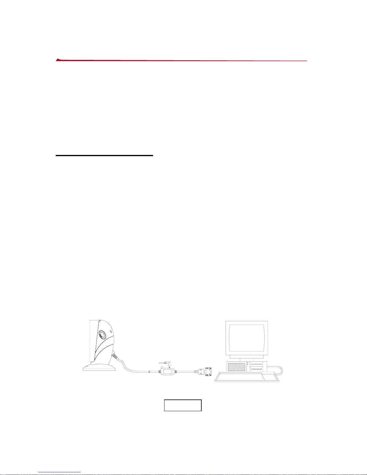
There are four type interface can support by the scanner,
1. RS-232C interface
Standard RS-232 connection to a host, proper
communication of the scanner with the host is set up by
scanning barcode menus.
1.) Make sure that the power of your computer system is
switched off.
2.) Plug the interface cable into the scanner port until a firm
“Click” sound is heard.
3.) Connect the other connector of the interface cable into
the appropriate port of your POS or terminal.
4.) Use a power +5V DC external power supply to the power
jack on the interface cable, if the RS-232C port of
computer system does not supply power.
5.) Switch on your computer system.
6.) Adjust the scanner’s parameters if necessary, by
scanning the appropriate labels in programming guide.
Serial RS-232 port of
PC or POS terminal
Figure 6
10
Page 16
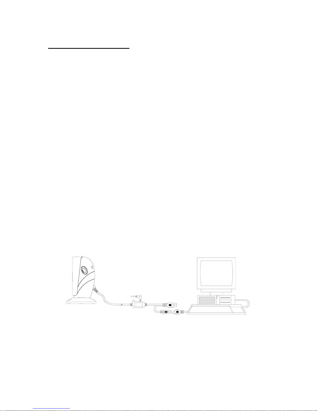
2. Keyboard Wedge
When configured for Keyboard Emulati on input, the host
accepts input from the scanner as keystrokes. The Z-6070
Series Scanner can perform Keyboard Emulation inp ut usi ng
a keyboard interface cable and a male to female connecting
cable.
1.) Make sure that the power of your computer system is
switched off.
2.) Plug the interface cable modular into the scanner port
until a firm
“Click” sound is heard.
3.) Connect the male end of the keyboard cable into the
female end of the interface cable.
4.) Connect the female end of male-to-female connecting
cable into the male end of the interface cable.
5.) Connect the male end of male-to-female connecting
cable into the keyboard port on the host
6.) Use a power +5V DC external power supply to the
power jack on the interface cable if the external power is
required.
7.) Switch on your computer system.
8.) Adjust the scanner’s parameters by scanning the
appropriate labels in programming guide, if necessary.
Keyboard connection of
PC or HOST system
Figure 7
11
Page 17
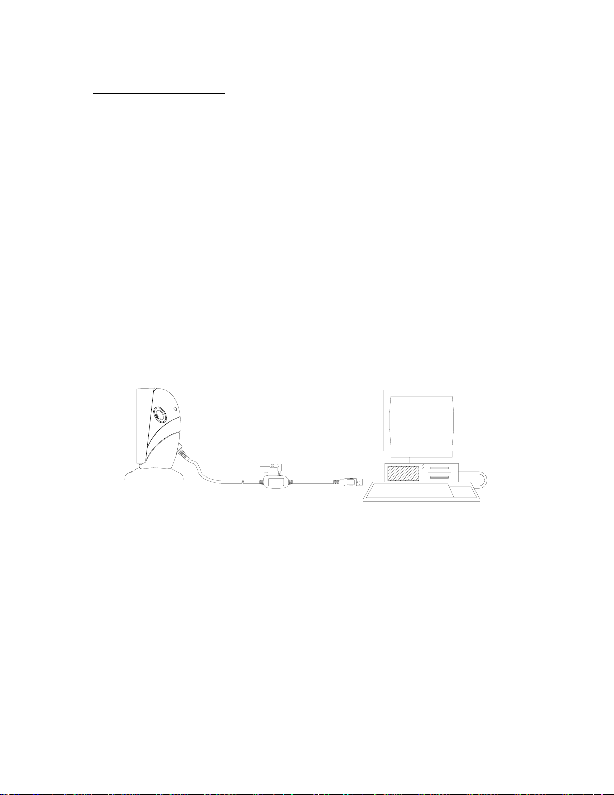
3. USB interface
Connect USB cable to a host. The scanner automatically
detects a USB host and defaults to the HID keyboard
interface type.
1.) Make sure that the power of your computer system is
switched off.
2.) Plug the interface cable modular into the scanner port
until a firm
“Click” sound is heard.
3.) Connect the other end of the interface cable into the
USB port on the host.
4.) Use a power +5V DC external power supply to the
power jack on the interface cable If the external power
is required.
5.) Switch on your computer system.
6.) Adjust the scanner’s parameters by scanning the
appropriate labels in programming guide, if necessary.
USB connection of
PC system
Figure 8
12
Page 18

13
4. Wand emulation
To perform Wand Emulation, the scanner can be connected
to a portable data terminal, or a controller that collects the
data as wand data, and interprets it for the host.
1.) Make sure that the power of your computer system is
switched off.
2.) Plug the interface cable modular into the scanner port
until a firm
“Click” sound is heard.
3.) Connect the other end of the interface cable into the
COM port on the PDT or controller.
4.) Use a power +5V DC external power supply to the
power jack on the interface cable if the external power is
required.
5.) Switch on your computer system
6.) Adjust the scanner’s parameters by scanning the
appropriate labels in programming guid e, if necessary.
It is our advice to turn off your POS or host system
before starting the installation of the scanner. By
following this procedure you can avoid from being
electronically damaged to your computer.
It is also our advice to install the scanner in an
air-circulated place but away from the direct sunlight.
Use only AC/DC power adaptor appr oved for the
Z-6070 scanner that ordered from ZEBEX. Usage of
other power supplies may cause damage to the
product, and the damage is not covered by the factory
warranty.
Page 19
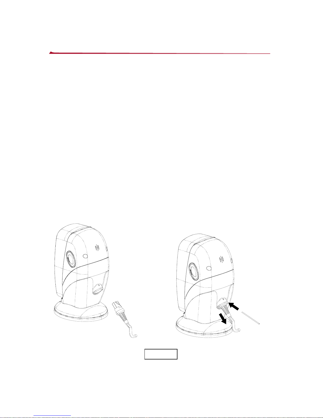
Replacing the Interface Cable
The standard interface cable is attached to the scanner with
an 8-pin modular I/O-connector. When properly seated, the
connector is secured in the scanner handle by a flexibl e
retention tab. The cable is designed to be field replaceable,
Replacement cable can be obtained from ZEBEX, or an
authorized distributor.
To replace the cable, the following steps should be followed.
1.) Make sure that the power of your computer system is
switched off.
2.) Disconnect the scanner cable from the computer
system.
3.) Use a pin to press down the small hole situated at the
back of the scanner where the cable is attached.
4.) Straighten one end of paper clip.
5.) Pressure down the pin, and pull the connector out, the
cable is loosed.
1
2
Figure 9
14
Page 20
How to Scan
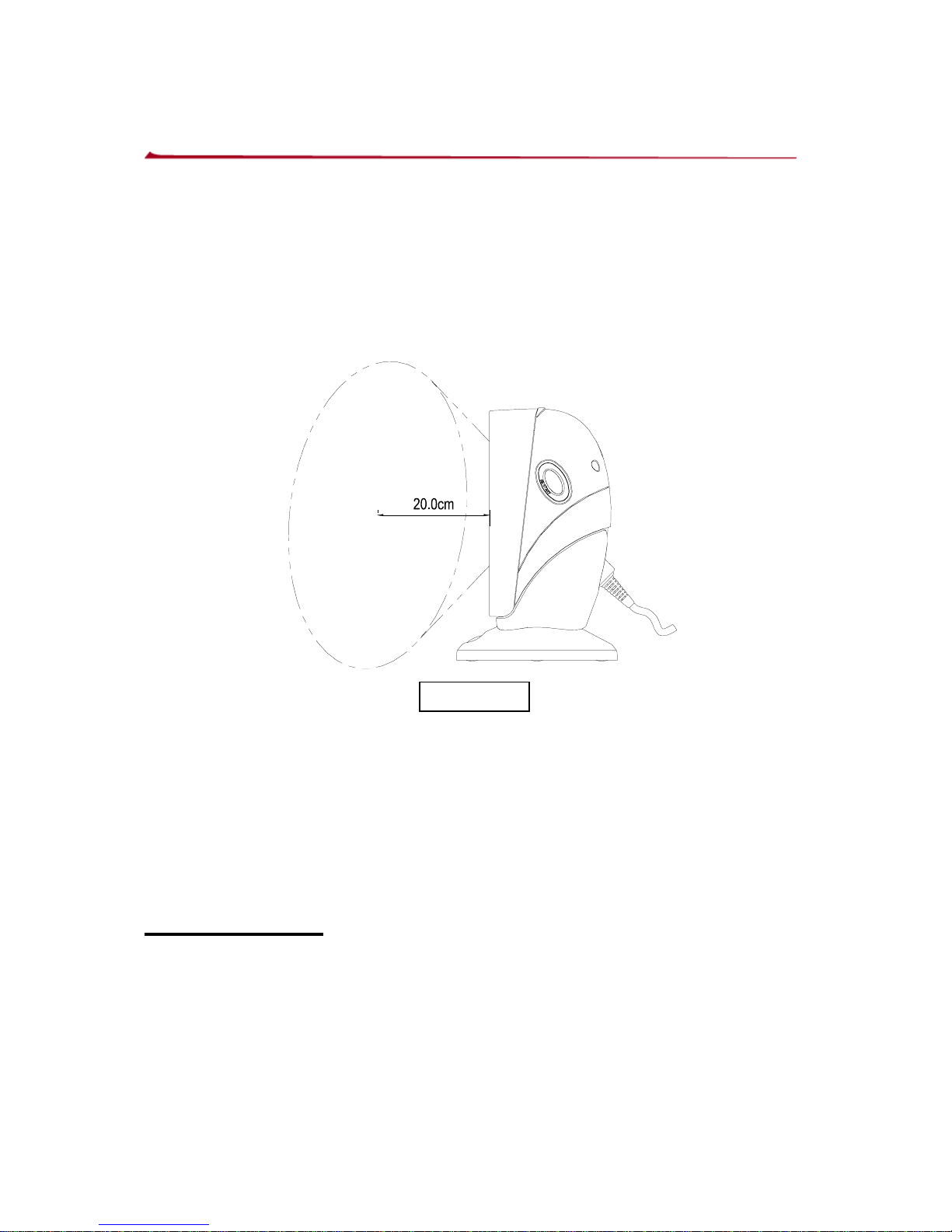
The Z-6070 is an omni-directional presentation scanner with
an 8 directional scan field with a 32 lines scan pattern. The
scan volume extends approximately 8”(20cm) in front of the
scan windows. Barcode labels can easily be read by
presenting towards to the scanning window.
The scanner’s scan volume is illustrated as Figure 10.
Figure 10
Scanning Operation
The Z-6070 support two pattern to scan barcode
z Multi-line scanning
z Single line scanning
Multi-line mode
In this mode, the front scan windows with its multi line scan
pattern, barcodes can easily be read by presenting them to
scanner
15
Page 21
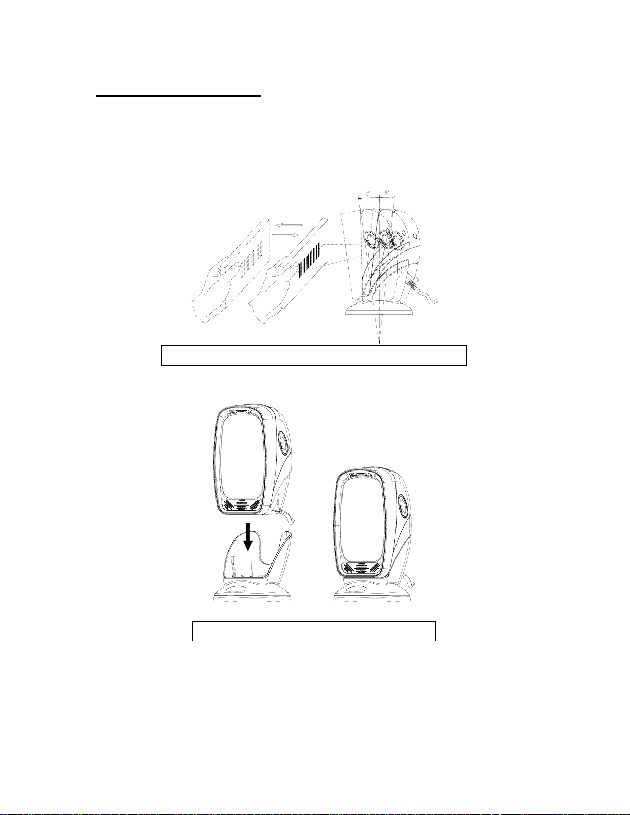
Fixed mode scanning
In this mode, the scanner can read barcodes either in the
sweep or presentation to accommodate different user styles.
The adjustable stand allows to be tilted forward and
backwards in position when scanning various sized objects,
as show in figure 11 ~ 16.
Figure 11 - scanner position adjustment
Figure 12 - scanner in the stand
16
Page 22
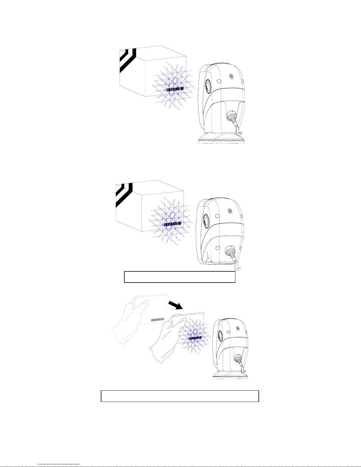
Figure 13 - With stand
Figure 14 - Without stand
Figure 15 - “Presentation” scanning
17
Page 23
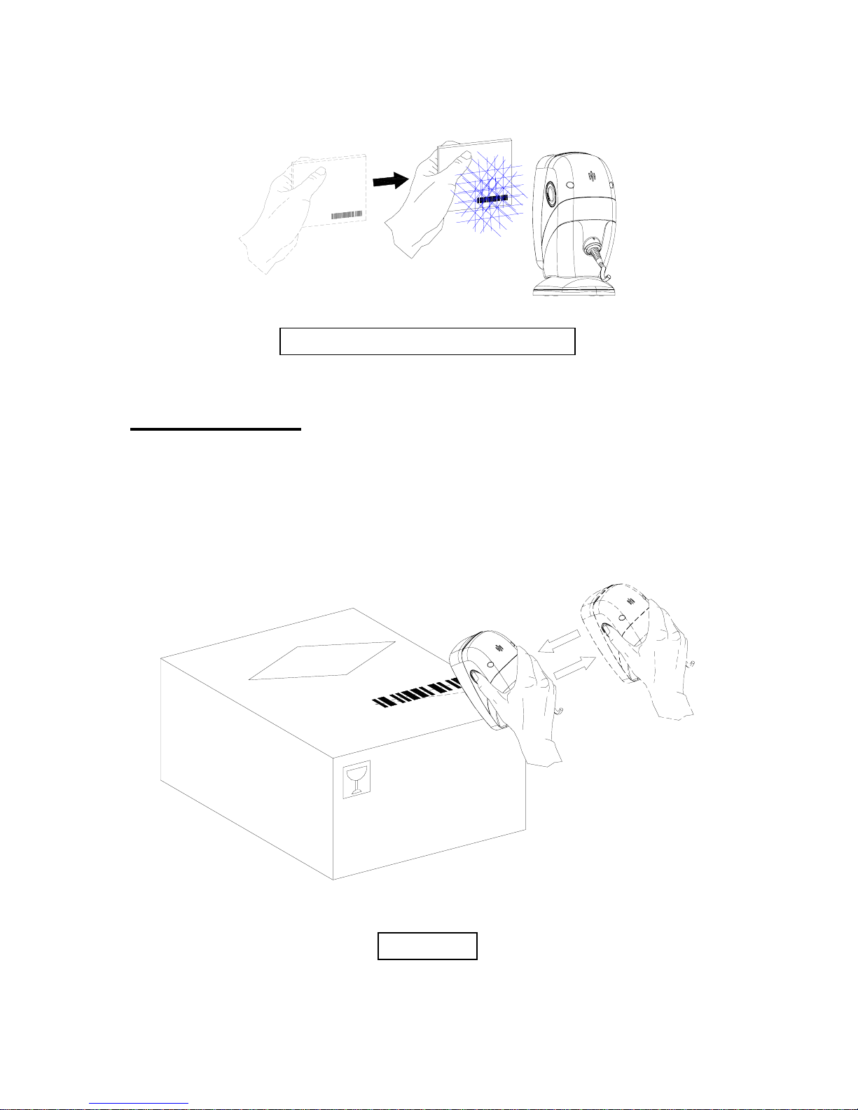
Figure 16 - “Sweep”Scaning
Hand held mode
The Z-6070 is also a handheld scanner, with a easy lift from
its adjustable stand, when scanning large or bulk items. To
use the scanner in hand held mode, remove the scanner from
stand and present the scanner’s front scan window towards
to the barcode to be scanned.
Figure 17
18
Page 24
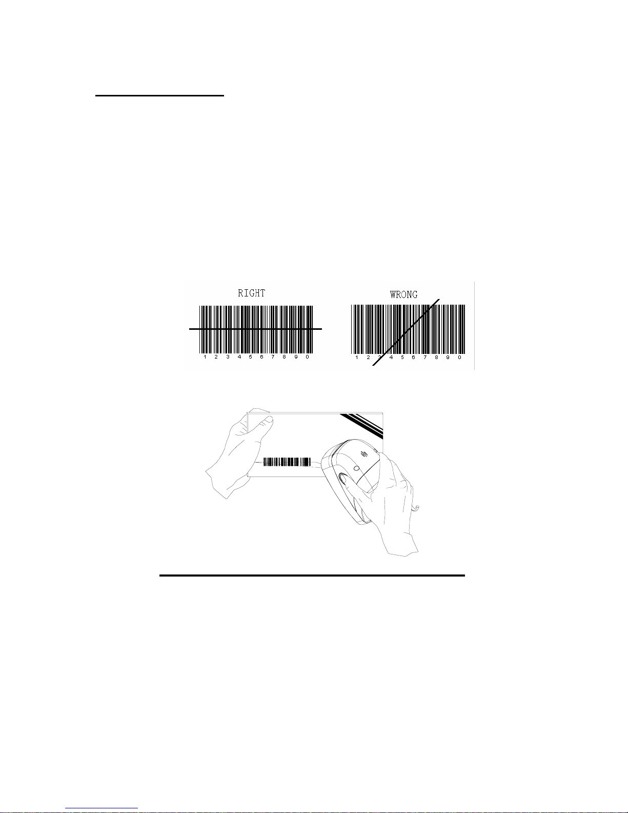
Single-line mode
In this mode the scanner can emit a single line pattern for
user to handheld scanning of hard to read or multiple
barcodes on one object, sales clerks could switch it to single
line scan option simply by pressing one button.
1. Pick up the scanner.
2. Press and then release the side button (left or right), a
line pattern appears, it allows you to aim at the barcode.
Ensure the scan line crosses every bar and space of the
symbol.
3. Press the button to decode and transmit the barcode, the
good read beeps once.
Figure 18 - scanning in single line mode
4. Release the button, it will remain the scan line at aim
mode, to read other barcode, you have to repeat
step ,3.4
5. After a duration of time (about 5 second) or by putting the
scanner back on the stand, the multi-line scan pattern is
displayed, and returned to multi line scan mode.
19
Page 25

Sleep mode
After the scanner has been inactive for an extended period of
time, the laser and/or motor automatically turns off and enter
“sleep mode”, and indicated by a blink of the Red light
(blinking at a 1-second rate). To wake up the unit, simply
present an object to the scanner window or press the button
at the sides.
The scanner takes 2 steps to enter the sleep mode, firstly,
laser off after 10 minutes, secondly, motor off after 30
minutes. The time period is programmable.
Note:
The scanner includes an object sensor that detects activity in
front of the scan window. The detectable distance is 50mm
range from exit window, in condition with effectiveness of
environment lights.
20
Page 26
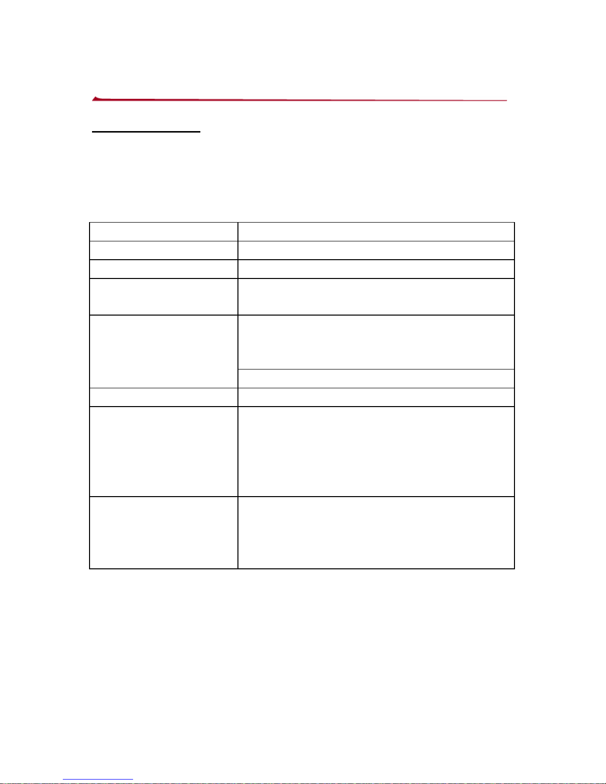
LED and Beeper Indications
LED indication
There are red and green dual color LED i ndications on the
head of the Z-6070 that indicates the operational status of the
scanner. The LED status with different indications are as
follows.
LED status Indication
Off No power apply to the scanner
Steady Red light The scanner is on and “ready to scan”
Flash Green light
once
A barcode has been successfully
decoded
A barcode has been successfully
decoded, but the object is not removed
from the scan window.
Steady Green light
The scanner is in programming mode.
Flash Red light The scanner enters to sleep mode
Steady Red/Green
light
This indicates the scanner has a motor
or laser failure
For motor failure also with a periodic
beeper is herad
Return the unit for repair.
Alternate flash Red
and Green light
The indicates the scanner detect a
failure power.
Please check your power whether
properly
21
Page 27
22
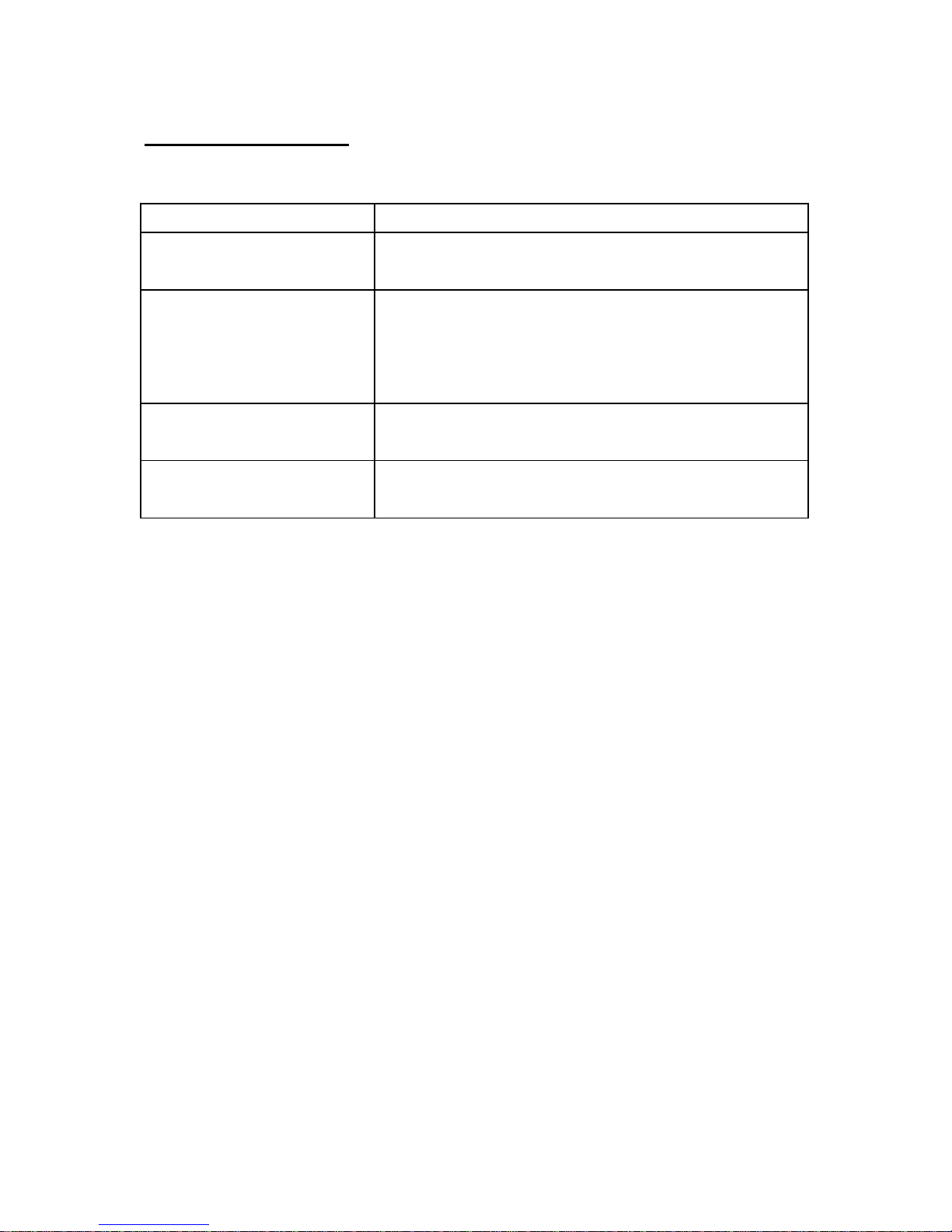
Beeper Indication
When the scanner is in operation, the sound indic ates the
statuses as follows.
Beeper Indication
One Beep A barcode has been successf ully
decoded.
Series three Beep 1.) This indicates the scanner passed
the self-test and is operating
properly.
2.) When the scanner is powered up.
Series two beep This indicates when you’re going i nto
programming
Continuous beep
tone
This is a failure indication. Return the
unit for repair.
Page 28

Changing Beeper Volume Using Push Button
The scanner can be programmed to change beeper tone,
volume and duration, the beeper volume can also be
changed by using push button.
The volume has 3 different selections, low, medium, loud,
which is operated follow the following steps.
1. Always keep the scanner in the stand
2. Press and hold down any one of the side buttons (left or
right) for about 5 seconds, the scanner will enter
(medium—low---loud) beeper cycle, every level of
setting beeps twice, user could release the button when
they hear the right beeps. The scanner beeps
accordingly.
Note:
The volume setting is not saved in non-volatile memory. That
means, the change will lost by powered-down and reset to
the configured setting.
If you wish to keep the changed the volume setting, use the
programming guide to set the changes.
23
Page 29

Maintaining the Scanner
The Z-6070 laser scanner rarely needs an y maintenance.
Only an occasional cleaning of the scanner window is
necessary in order to remove dirt and fingerp rints. The
cleaning of the scanner window can be done during operation
with a soft lint-free cloth and a non-abrasive cleaner to avoid
scratching.
24
Page 30
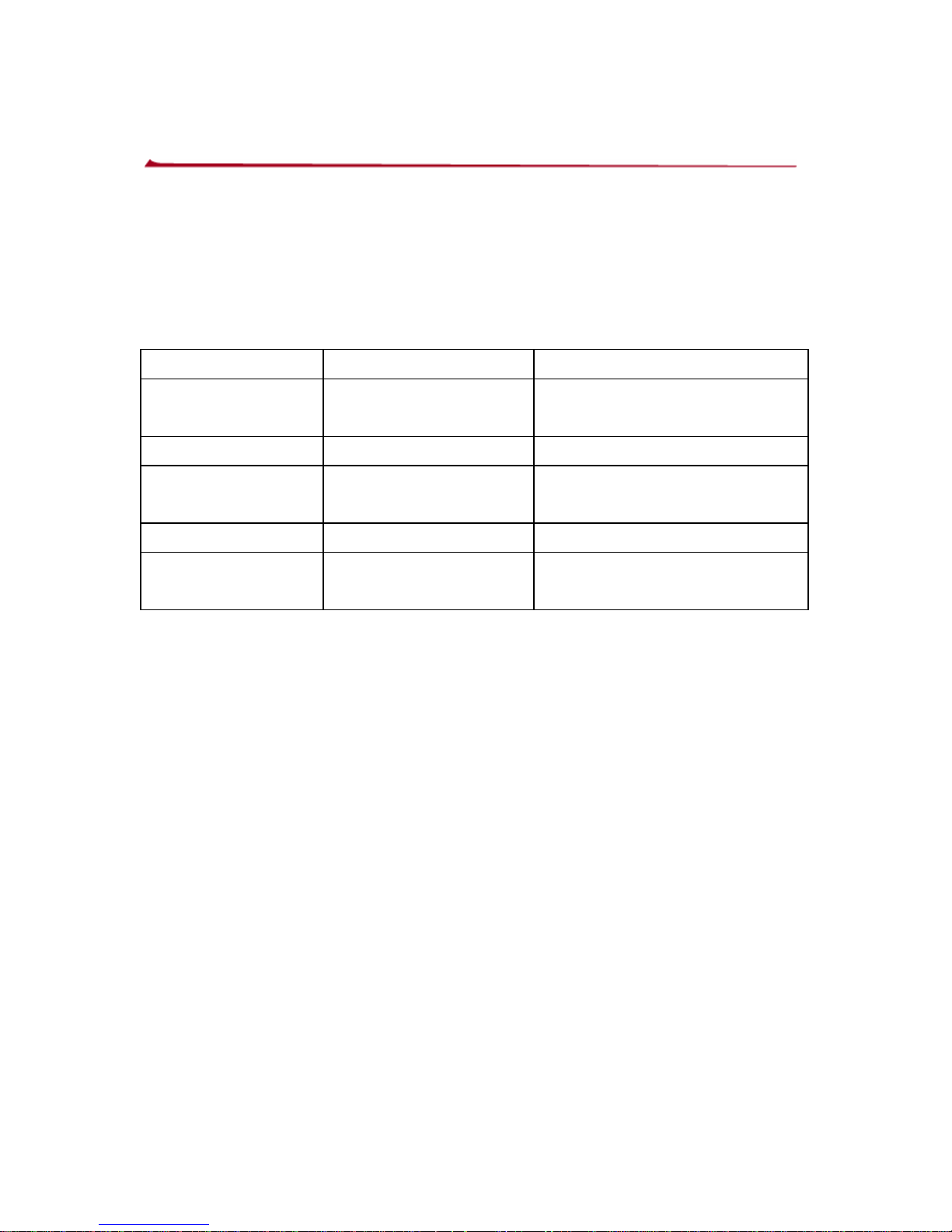
Controlling Scanner from the POS System
Z-6070 can be controlled from the POS system via the
RS-232C interface. Controlling can be accomplished by
transmitting the following single byte commands to the
scanner. The default setting of the commands are as
follows:
ASCII Code Function Byte is Also Called:
OE Hex enable (resumes
disable)
Shift Out or <Ctrl-N>
OF Hex disable Shift In or <Ctrl-O>
05 Hex power-up
re-initialization
ENQ or <Ctrl-E>
12 Hex sleep DC2 <Ctrl-R>
14 Hex wake up (resumes
sleep)
DC4 <Ctrl-T>
When the scanner is disabled, the motor of the scanner will
stay on until the scanner goes into sleep mode.
25
Page 31

Laser Safety
Z-6070 laser scanner complies with safety standard IEC
60825 for a Class I laser product. It also complies with
CDRH as applicable to a Class IIa laser product. Avoid long
term viewing into direct laser light.
Optical: The use of optical instruments with this product will
increase eye hazard. Optical instruments include binoculars,
microscopes and magnifying glasses but do not include eye
glasses worn by the user.
Radiant Energy: Z-6070 uses a low-power laser diode
operating at 650nm in an opto-mechanical scanner resulting
less than 0.7 mW peak output power. in an opto-mechanical
scanner, resulting in less than 3.9µW radiated power as
observed through a 7mm aperture and averaged over 10
seconds.
Do not attempt to remove the protective housing of the
scanner, as unscanned laser light with a peak output up to
0.8mW would be accessible inside.
Laser Light Viewer: The scanner window is the only
aperture through which laser light may be observed on this
product. A failure of the scanner motor, while the laser diode
continues to emit a laser beam, may cause emission levels to
exceed those for safe operation. The scanner has
safeguards to prevent this occurrence. If, however, a
stationary laser beam is emitted, the failing scanner should
be disconnected from its power source immediately.
26
Page 32

27
Adjustments: Do not attempt any adjustments or alteration
of this product. Do not remove the protective housing of the
scanner. There are no user-serviceable parts inside.
Caution: Use of controls or adjustments or performance
of procedures other than those specified herein may
result in hazardous laser light exposure.
Page 33

APPENDIX
28
TECHNICAL SPECIFICATION
Page 34
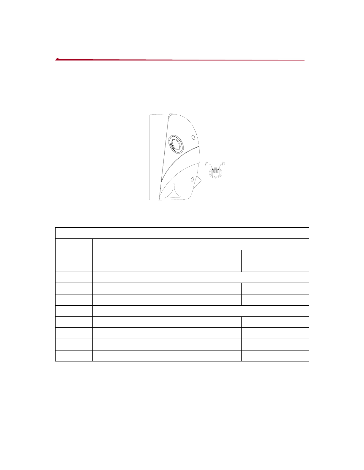
Appendix A: Connector and Pin out
The Z-6070 has multi interface: RS232, Keyboard Wedge,
wand emulation and USB, all in one. The pin definition for the
scanner port and the connector to be used for the port are
shown in the connection diagram below.
Pin out Configuration
Function
PIN#
Keyboard We dge RS-232C
Wand
emulation
1 DC +5V input
2 Keyboard Clock N.C. N.C
3 PC Clock RTS_CMOS N.C.
4 Ground
5 N.C TXD_CMOS N.C
6 N.C RXD_CMOS N.C
7 Keyboard Data N.C. N.C
8 PC Data CTS_CMOS Data out
Note:
The USB interface is via RS-232 port pin transfer to cable.
29
Page 35

Appendix B: Specifications
Electrical
DC Input To Scanner 5V±5%
Power Consumption 1.25 watts
Power Current 250 mA@5V
Interfaces
RS232C Interface
Keyboard Emulation
(IBM PC/AT, PS/2 compatible)
USB interface
Optical
Light Source
650 ± 5 nm visible laser diode
Depth Of Field 210 mm (8 inches)
Scan Pattern
10 direction scan field, 32 line scan
pattern
Environmental
Operating Temperature
0℃ ~ 40℃
Storage Temperature
-20℃ ~ 60℃
Humidity 5% ~ 95% RH (non-condensing dew)
Ambient Light Rejection
4000 LUX (fluorescence)
Print Contrast Value 30% or more
Mechanical
Scanner 187g (excl.cable)
Weight
Stand 197g
Scanner 135.59(L)x67.5(W)x81.75(D) (mm)
Dimensions
Stand 100(L)x70(W)x70.5(D) (mm)
30
Page 36
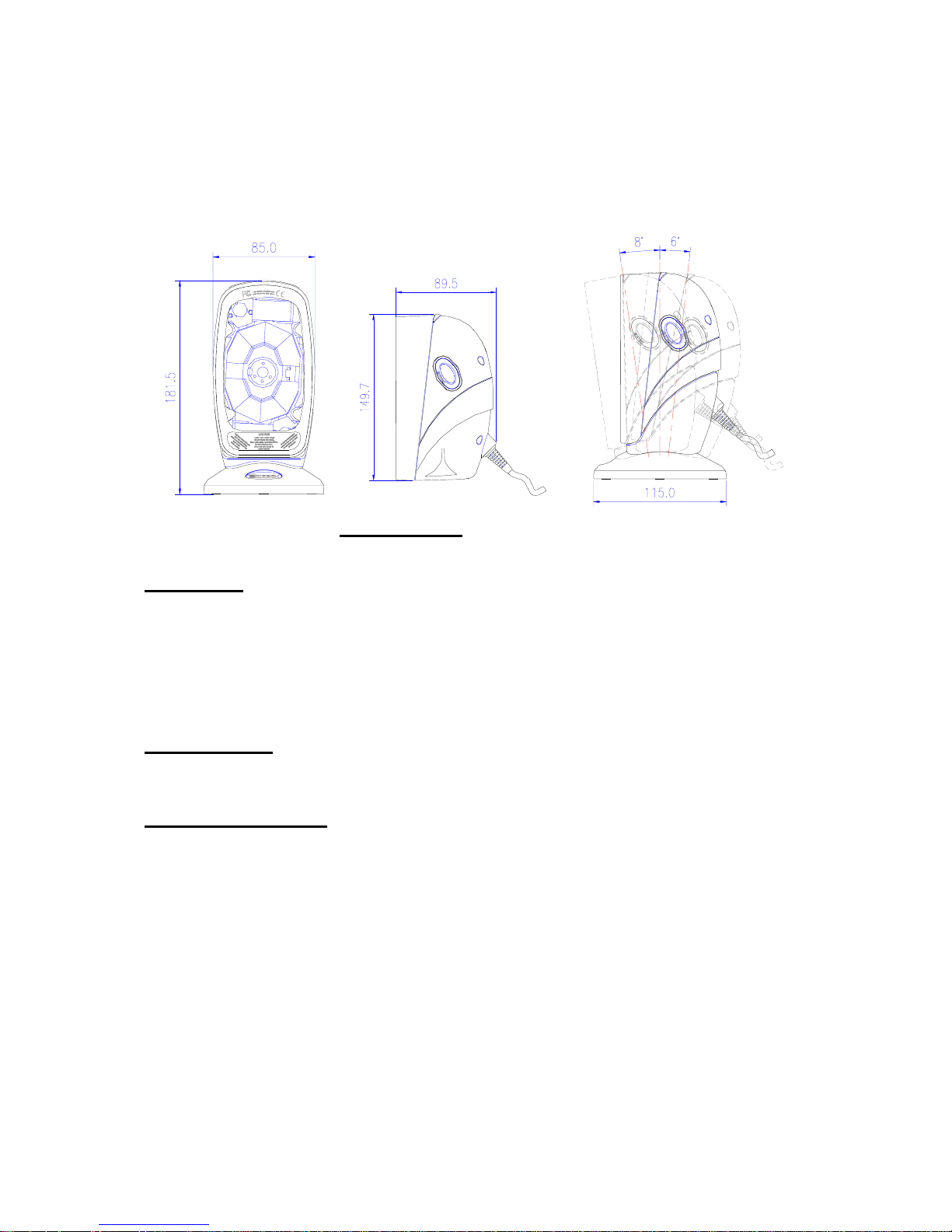
Cable
length
Straight 2M
Dimensions
Decoding
Barcode Types EAN/UPC/JAN + Add-on Code 128, EAN
128,
Code 39, Code 32, Code 93,Codabar,
Interleaved 2 of 5,MSI / Plessy, Chinese
post code,RSS14(optional)
Laser Safety
CDRH class IIa, IEC 60825 class1
EMCl Compliance
CE EN55022,B, FCC part 15 Class
A,VCCI,BSMI
31
Page 37

Appendix C: Trouble-shooting
This section contains information about how to solve
problems that you may encounter when operating the
scanner. If troubles occur, please refer to the following
diagnostic tips as a mean to solve the trouble. However,
before referring to the tips, make sure that the scanner is
installed as instructed in this manual and that all cables are
properly connected. If the problem remains, contact your
dealer .
Problem Diagnostic Tips
The scanner is on
but cannot read
barcodes. The
LED is red.
z The scanner window is dirty.
Clean the scanner window as
described in the Maintenance
section.
z The presented barcode type is
not enabled. Select the barcode
type with the Programming
Guide.
z The host disables the scanner.
z The barcode type you presented
to the scanner is not supported by
Z-6070
The scanner is on,
but the motor is not
rotating. A barcode
cannot be read.
The LED is
intermittently
flashing red.
z The scanner has entered into the
sleep mode. Press the switch
on the side or front of the scanner
to wake up the scanner (or use
the wake protocol. )
The LED is remain z Possible failure of the scanning
32
Page 38

33
red and Green safeguard circuit. Disconnect
the scanner from its power source
immediately and contact your
dealer .
The scanner does
not accept more
than two or three
barcode labels.
z There is no proper handshaking
with the POS system. Switch on
the POS system and check
connection and communication
settings.
z The scanner is continuously
seeing a barcode. Remove all
barcode labels out of the scan
volume of the scanner and try
again.
z The scanner cannot send the
data to the POS system. There
is no proper handshaking
between the scanner and the
host. Make sure that all cables
are connected and your POS
system is ready to receive data.
A barcode is read by
the scanner but not
accepted by the
POS system.
The communication cable is not
connected to the serial port of your
POS system. Refer to the
manual of your POS system to
locate the serial port.
The communication settings of the
system and scanner do not match.
Adjust the settings in order to be
equal for both devices.
The communication cable does
Page 39

34
not suit your POS system..
Contact your dealer for the correct
communication cable.
z The software running on the POS
system does not support the data
format of the label.
 Loading...