

Page 1
1
Settings and Programming
For
2D Image Scanners
Page 2

i
Copyright © 2010. All rights reserved.
No warranty of any kind is made in regard to this material, including, but not
limited to, implied warranties of merchantability or fitness for any particular
purpose. We are not liable for any errors contained herein nor for incidental
or consequential damages in connection with furnishing, performa nce or use
of this material. We shall be under no liability in respect of any defect arising
from fair wear and tear, willful damage, negligence, abnormal working
conditions, failure to follow the instructions and warnings, or misuse or
alteration or repair of the products without written approval. No part of this
document may be reproduced, transmitted, stored in a retrieval system,
transcribed, or translated into any human or computer or other language in
any form or by any means electronic, mechanical, magnetic, optical,
chemical, biological, manual or otherwise, except for brief passages which
may be quoted for purposes of scholastic or literary review, without express
written consent and authorization. We reserve the right to make changes in
product design without reservation and without notification. The material in
this guide is for information only and is subject to change without notice. All
trademarks mentioned herein, registered or otherwise, are the properties of
their various, ill, assorted owners.
General handling precautions
Do not dispose of the scanner in fire.
Do not put the scanner directly in the sun or by any heat source.
Do not use or store the scanner in a very humid place.
Do not drop the scanner or allow it to collide violently with other objects.
Do not take the scanner apart without a uthorization.
Page 3

ii
Radio Frequency Interference Requirements
This equipment has been tested and found to comply with the limits for a
Class B digital device, pursuant to part 15 of the FCC rules. These limit s are
design to provide reasonable protection against harmful interference in a
residential installation. This equipment generates, uses and can radiate
radio frequency energy and, if not installed and used in accordance with the
instructions, may cause harmful interference to radio communications.
However there is no guarantee that interference will not occur in a particular
installation. If this equipment does cause harmful interference to radio or
television reception, which can be determined by turning the equipment off
and on, the user is encouraged to try to correct the interference by one or
more of the following measures:
Re-orientate the receiving antenna
Increase the separation between the equipment and receiver
Connect the equipment into an outlet on a circuit different from that to
which the receiver is connected
Consult the dealer or an experienced radio/TV technician for help.
For CE-Countries:
It is in conformity with the CE standards. Please note that a CE-Marked
power supply unit should be used to conform to these standards.
Laser Devices
The devices using lasers comply with US 21CFR1040.10 and 1040.11
except for deviations pursuant to Laser Notice No. 50 dated July 26, 2002
and IEC608525-1:+A1:1997+A2:2001 The laser classification is marked on
one of the labels on the devices.
Class 1 Laser devices are not considered to be hazardous when used for
their intended purpose. The following statement is required to comply with
US and international regulations:
Caution: Use of controls, adjustment or performance of procedures other
than those specified herein may result in hazardous laser light exposure.
Class 2 laser scanners use a low power, visible light diode. As with any
bright light source, such as the sun, the user should avoid staring directly
into the light beam. Momentary exposure to a Class 2 laser in not known to
be harmful.
Page 4

1
Important Notice
1. This document is in A5 size. Please check your printing setting before
printing it out.
2. When printing barcodes for programming, the use of a high-resolution
laser printer is strongly suggested for the best scan result.
3. The settings shall be updated periodically without prior notice. For the
latest version, please contact your authorized distributor.
Settings and Programming
Scan a series of selected barcode pat ches in this man ual to af fect setup and
programming of your handheld 2D Image Reader. Decoding options and
interface protocols can be tailored to a specific application. Setup
parameters are stored in non-volatile memory in the scanner and are
retained even when power is off. Setup parameters change only when you
reset them.
Throughout the programming guide, default values are indicated with square.
You may need to hide adjacent code patches with you r hand when scanning.
Programming Options
This section contains the following two divisions:
Default factory device settings.
Supported symbologies.
Page 5
2
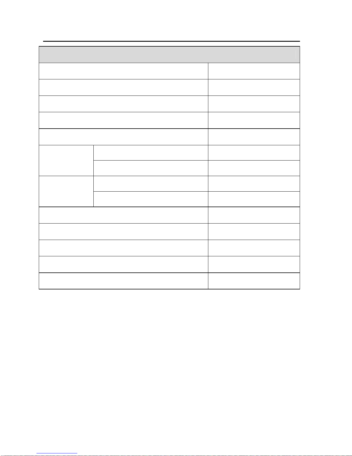
Default Factory Device Settings
User Preferences
Parameter Default
Set Default Parameter All Defaults
Parameter Scanning Enable
Beeper Tone Medium
Beeper Volume High
Handheld/Hands-free Scanner Level
Trigger Mode
Scan Module Presentation
Handheld/Hands-free Scanner Low Power
Power Mode
Scan Module Continuous on
Time Delay to Low Power Mode 1.0 Sec
Decode Session Timeout 9.9 Sec
Timeout Between Decodes, Same Symbol 0.6 Sec
Beep After Good Decode Enable
Presentation Mode Session Timeout 2 Seconds
Page 6
3
User Preferences
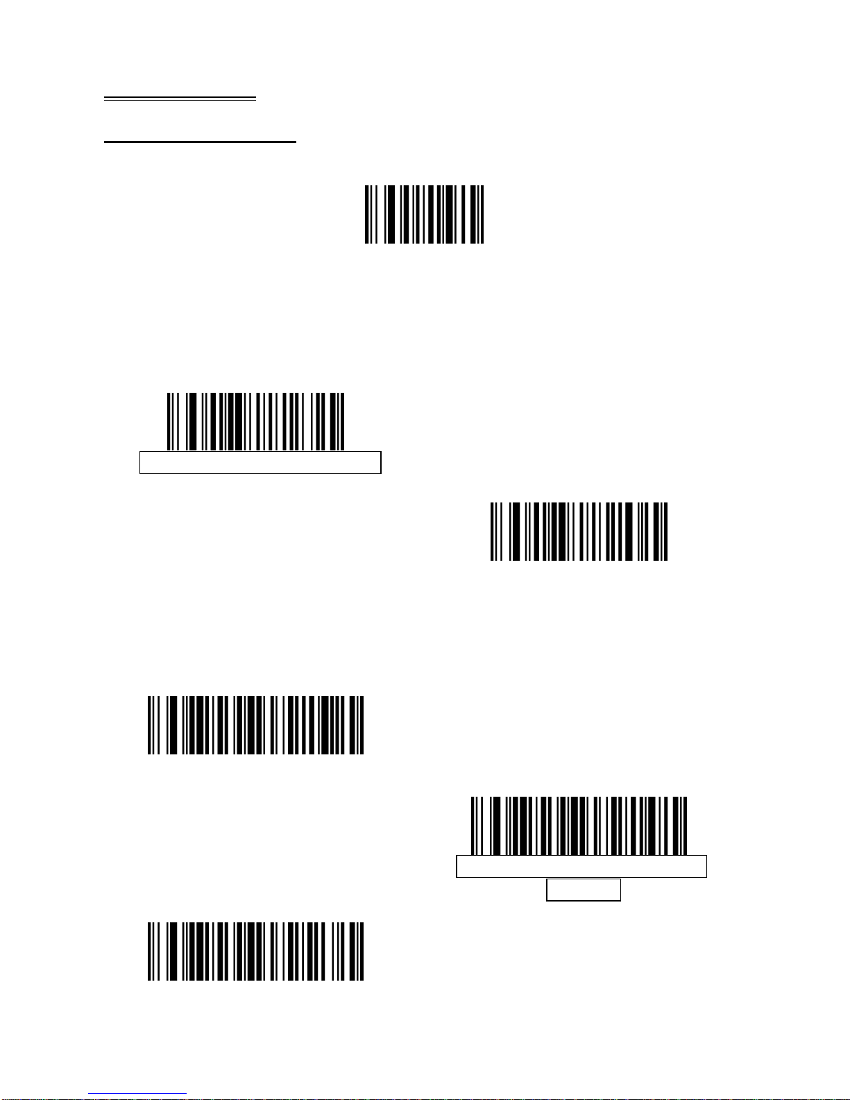
Set Default Parameter
Scan this bar code to return all parameters to the default values.
Set All Defaults
Parameter Scanning
To disable decoding of parameter bar codes, including the Set All Defaults
parameter bar code, scan the Disable Pa ram eter S canning bar code belo w. To
enable decoding of parameter bar cod es, scan Enable Parameter Scanning.
Enable Parameter Scanning
Disable Parameter Scanning
Beeper Tone
To select a decode beep frequency (tone); scan the Low Frequency, Medium
Frequency, or High Frequency bar code.
Low Frequency
Medium Frequency (Optimum
Setting)
High Frequency
Page 7

4
Beeper Volume
To select a beeper volume, scan the Low Volume, Medium Volume, or High
Volume bar code.
Low Volume
Medium Volume
High Volume
Page 8
5
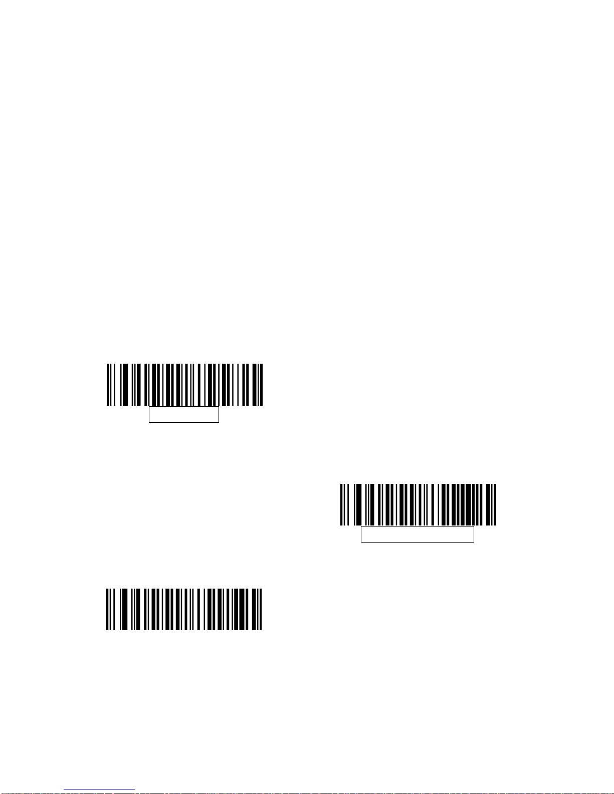
Trigger Modes
Level Mode - A trigger event activates decode processing, which
continues until the trigger event ends, a valid decode, or the
decode session time-out is reached. This scan mode is not
available for scan module.
Presentation Mode - When the device detects an object in its field
of view it triggers and attempts to decode. The range of object
detection does not vary under normal lighting conditions. This
applies to decode mode only. In this mode the unit does not enter
its sleep state.
Host Mode- A host command issues the triggering signal. The
device interprets a trigger pull as a level triggering option. This scan
mode is not available for scan module.
Level Mode
(Default for handheld/hands-free
scanners.)
Presentation Mode
(Default for scan module.)
Host Mode
Page 9
6
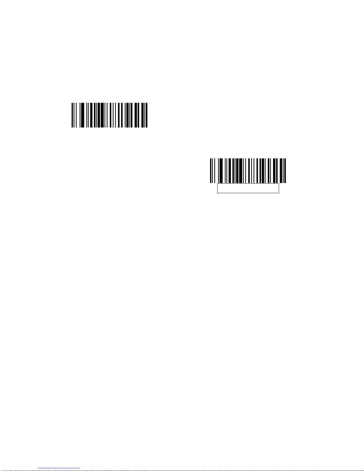
Power Mode
This parameter determines whether or not power remains on after a decode
attempt. In low power mode, the decoder enters into a low power consumption
mode to preserve battery life after each decode attempt. In continuous power
mode, power remains on after each decode attempt.
Continuous On
(Default for scan module)
Low Power Mode
(Not available for scan module)
Page 10
7
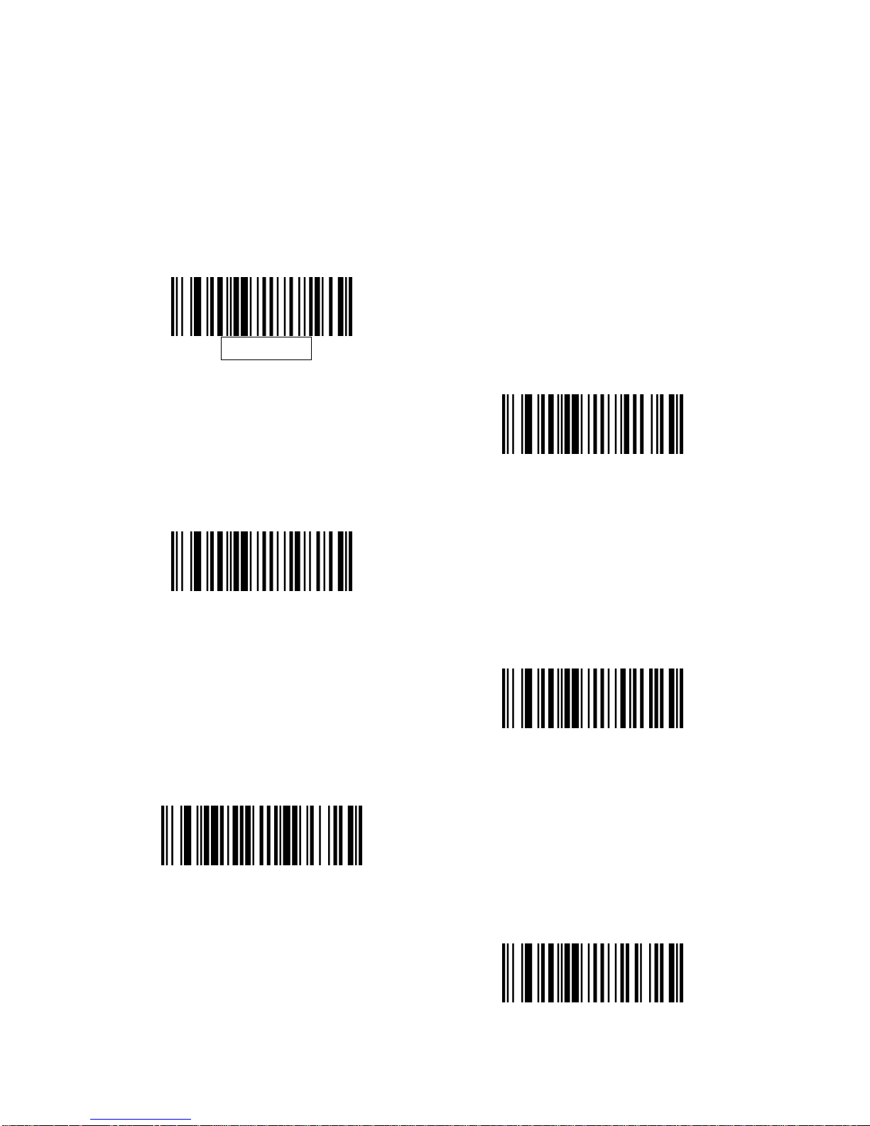
Time Delay to Low Power Mode
This parameter sets the time the decoder remains active after decoding. The
decoder wakes upon trigger pull or when the host attempts to communicate
with the decoder.
Note: 1. This parameter only applies when Power Mode is set to Low Power.
2. This setting is not available for scan module since it is always in
presentation mode and its power is continuous on.
1 Second
5 Seconds
1 Minute
5 Minutes
15 Minutes
1 Hour
Page 11
8
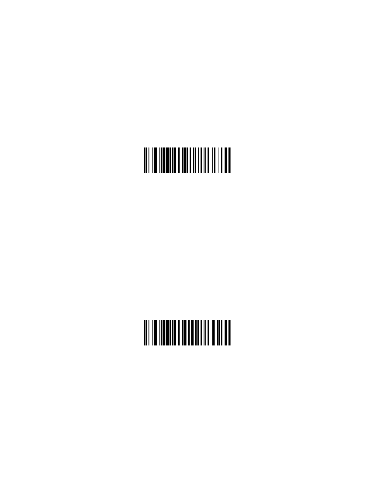
Decode Session Timeout
This parameter sets the maximum time decode processing continues during a
scan attempt. It is programmable in 0.1 second increments from 0.5 to 9.9
seconds. The default timeout is 9.9 seconds.
To set a Decode Session Timeout, scan the bar code below. Next, scan two
numeric bar codes from Appendix D, Numeric Barcodes that corres pond to the
desired on time. Single digit numbers must have a leading zero. For example,
to set a Decode Session Timeout of 0.5 se conds, scan the b ar code below, an d
then scan the 0 and 5 bar codes. To correct an error or change the selection,
scan Cancel barcode.
Decode Session Timeout
Timeout Between Decodes, Same Symbol
This option is used in presentation mode to prevent multiple reads of a symbol
left in the Device’s field of view. The timeout begins when the symbol is
removed from the field of view. It is programmable in 0.1 second increments
from 0.0 to 9.9 seconds. The default interval is 0.6 seconds.
To select the timeout between decodes for the same symbol, scan the bar
code below, then scan two numeric bar codes from Appendix D, Numeric Bar
Codes that correspond to the desired interval, in 0.1 second increments.
Timeout Between Decodes, Same Symbol
Page 12
9
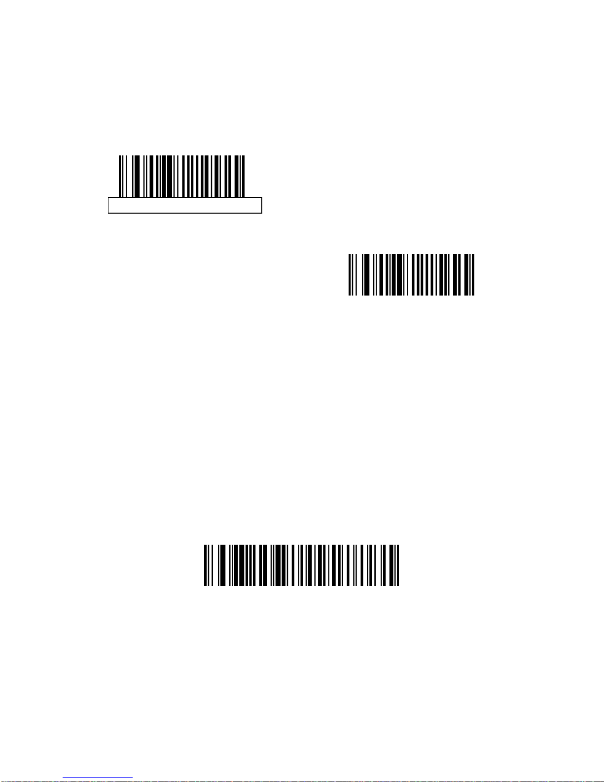
Beep After Good Decode
Scan a bar code below to select whether or not the decoder issues a beep
signal after a good decode. If selecting Do Not Beep after Good Decode,
beeper signals are issued during parameter menu scanning and to indicate
error conditions.
Beep After Good Decode
Do Not Beep After Good Decode
(Disable)
Presentation Mode Session Timeout
To set the duration of the attempt to decode a bar code detected in
presentation mode, scan the bar code below. Next, scan three numeric bar
codes from Appendix D, Numeric Bar Codes to select a value between 1 and
255 that represents tenths of a second. Single digit numbers must have a
leading zero. For example, to set 0.5 seconds, scan the bar code below, then
scan the 0, 0, 5 bar codes. The default value is 2 seconds.
Presentation Mode Session Timeout
Page 13
10
Imager Preferences
Imaging Options
Parameter Default
Decoding Auto exposure Enable
Decoding Illumination Enable
Decode Aiming Pattern Enable
Image Capture Auto exposure Enable
Image Capture Illumination Enable
Gain 100
Exposure Time 10 ms
Snapshot Mode Timeout 0 (30 seconds)
Snapshot Aiming Pattern Enable
Image Cropping Disable
Crop to Pixel Addresses 0 top, 0 left, 479 bottom, 639 right
Image Resolution Full
JPEG Image Options Quality
JPEG Quality Value 65
JPEG Size Value 40 (41K)
Image File Format Selection JPEG
Bits per Pixel (BPP) 8 BPP
Signature Capture Disable
Signature Capture Image File Format
Selection
JPEG
Page 14
11
Signature Capture Bits per Pixel
(BPP)
8 BPP
Signature Capture Width 400
Signature Capture Height 100
Signature Capture JPEG Quality 65
Video View Finder Disable
Target Video Frame Size 2200 bytes
Video View Finder Image Size 1700 bytes
The parameters in this section control image capture characteristics.
Image capture occurs in all modes of operation, including decode, video,
and snapshot.
The decoder has three modes of operation:
* Decode Mode
* Snapshot Mode
• Snapshot with Viewfinder Mode
* Video Mode.
Page 15

12
Decode Mode
By default, upon a trigger event, the decoder attempts to locate and decode
enabled bar codes within its field of view. The decoder remains in this mo de a s
long as the trigger is active or until a bar code is decoded.
Snapshot Mode
Use Snapshot Mode to capture a high-quality image and transmit it to the host.
To temporarily enter this mode scan the Snapshot Mode bar code. While in this
mode the decoder blinks the green LED at 1-second intervals to indicate it is
not in standard operating (decode) mode.
In Snapshot Mode, the decoder turns on the laser aiming pattern to highlight
the area to be captured in the image. The next trigger event instructs the
decoder to capture a high quality image and transmit it to the host. A short time
may pass (less than 2 seconds) between when the trigger is activated and the
image is captured as the decoder adjusts to the lighting conditions. Hold the
decoder steady until the image is captured, denoted by a single beep.
If a trigger event is not activated within the Snapshot Mode Timeout period, the
device returns to Decode Mode. Use Snapshot Mode Timeout to adjust this
timeout period. The default timeout period is 30 seconds.
To disable the laser aiming pattern during Snapshot Mode, see Snapshot
Aiming Pattern.
Use Video View Finder to enable Snapshot with Viewfinder Mode. In this mode
the decoder behaves as a video camera until the trigger is active, at which time
a Snapshot is performed as described above.
Snapshot Mode
Page 16
13
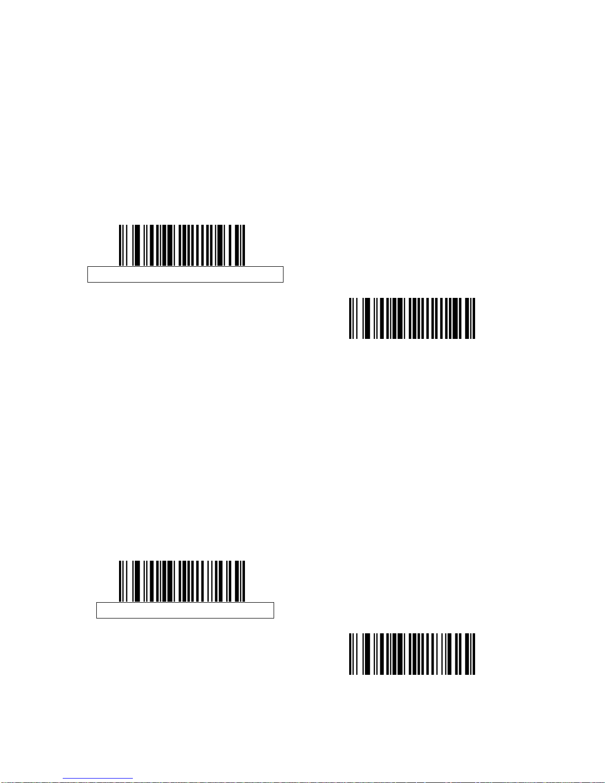
Decoding Auto Exposure
Select Enable Auto exposure to allow the device to control gain settings and
exposure (integration) time to best capture an image for the selected operation
mode.
Select Disable Auto exposure to manually adjust the gain and exposure time.
This option is only recommended for advanced users with difficult image
capture situations.
Enable Decoding Auto exposure
Disable Decoding Auto exposure
Decoding Illumination
Selecting Enable Illumination causes the decoder to flash illumination on every
image capture to aid decoding. Select Disable Illumination to prevent the
decoder from using decoding illumination.
Enabling illumination usually results in superior images. The effectiveness of
the illumination decreases as the distance to the target increases.
Enable Decoding Illumination
Disable Decoding Illumination
Page 17
14
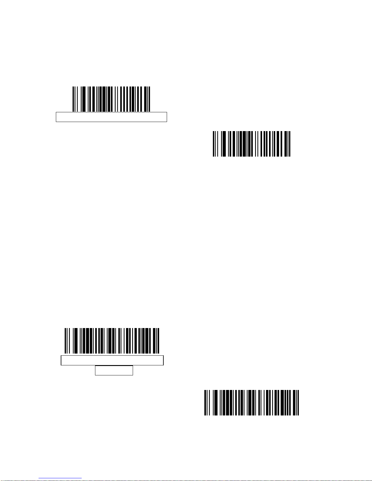
Decode Aiming Pattern
This parameter only applies when in Decode Mode. Select Enable Decode
Aiming Pattern to project the aiming pattern during bar code capture, or
Disable Decode Aiming Pattern to turn the aiming pattern off.
Enable Decode Aiming Pattern
Disable Decode Aiming Pattern
Image Capture Auto exposure
Select Enable Auto exposure to allow the decoder to control gain settings and
exposure (integration) time to best capture an image for the selected operation
mode.
Select Disable Auto exposure to manually adjust the gain and exposure time.
This option is only recommended for advanced users with difficult image
capture situations.
Enable Image Capture Auto
exposure
Disable Image Capture Auto
exposure
Page 18
15
Image Capture Illumination
Selecting Enable Image Capture Illumination causes the decoder to flash on
every image capture. Select Disable Illumination to prevent the decoder from
using artificial illumination.
Enabling illumination usually results in superior images. The effectiveness of
the illumination decreases as the distance to the target increases.
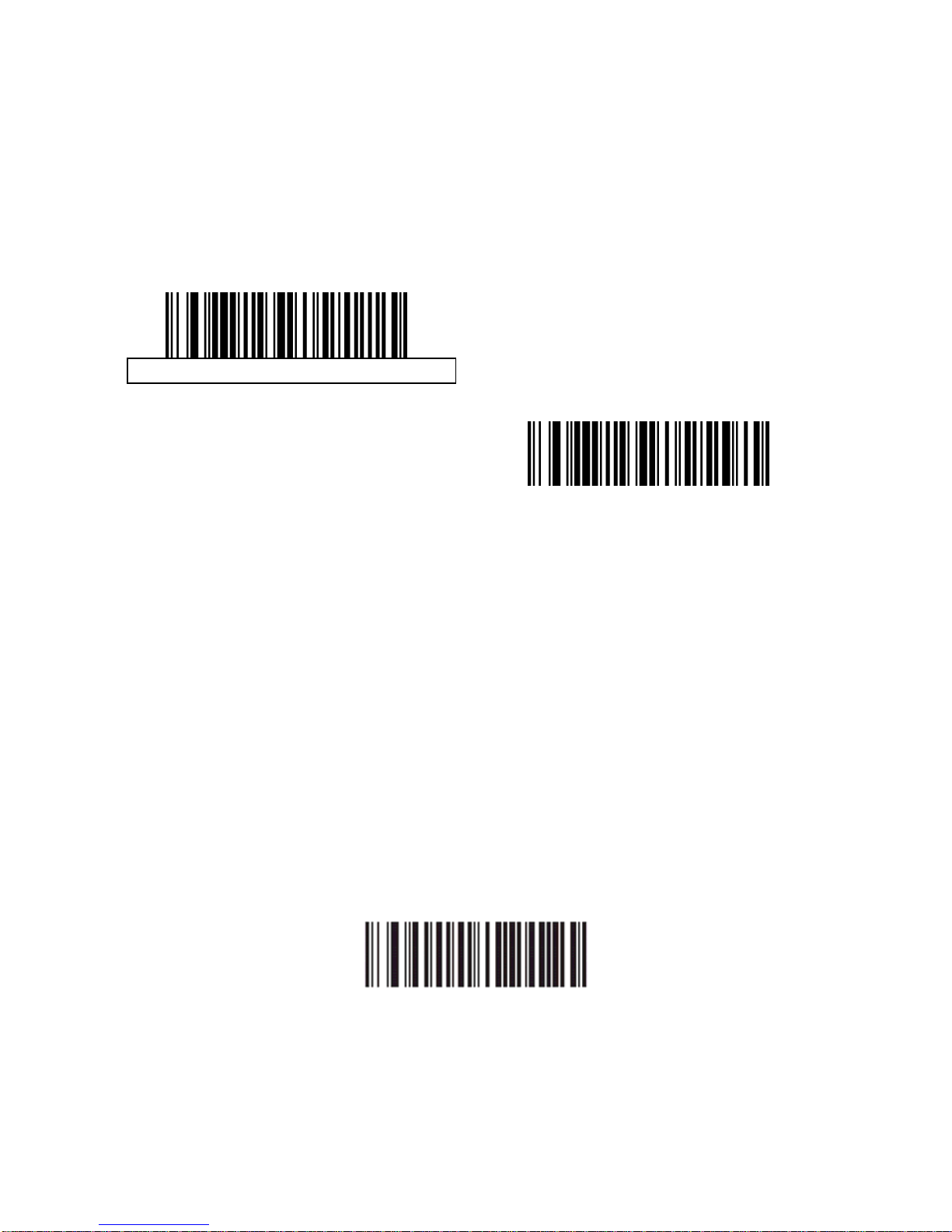
Enable Image Capture Illumination
Disable Image Capture Illumination
Gain
This parameter only applies when Decoding or Image Capture Auto exposure
is disabled. Gain is a means of amplifying the raw image data before it is
converted into 256 grayscale values. Increasing the gain increases brightness
and contrast, but also increases noise (undesired electrical fluctuations in the
image) which makes the image less attractive and/or harder to decode.
To set the manual gain, scan the bar code below followed by 3 bar codes from
Appendix D, Numeric Bar Codes, in the range of 79 to 127, representing the
value. The default is 100.
Set Gain
Page 19
16
Exposure Time
This parameter is only available when Image Capture Auto exposure is
disabled. Exposure Time controls the amount of time the CCD is allowed to
collect light, much like the shutter speed for a camera. Generally, the brighter
the environment, the shorter the exposure time. Set the manual exposure
time to one of the following values: 5 ms, 10 ms, 15 ms, 20 ms, 25 ms, or 30
ms. Increasing the exposure time past 20 ms in a handheld application
increases the risk of blurring the image due to hand jitter.
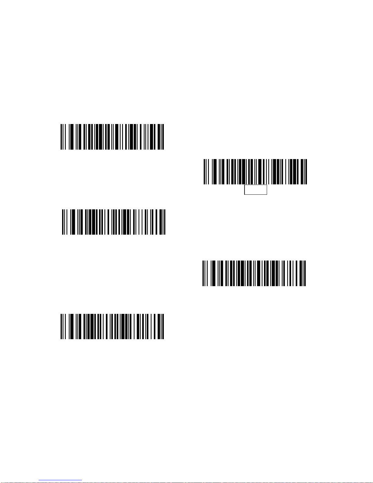
5 ms
10 ms
15 ms
20 ms
30 ms
Page 20
17
Snapshot Mode Timeout
This parameter sets the amount of time the decoder remains in Snapshot
Mode. The decoder exits Snapshot Mode upon a trigger event, or when the
Snapshot Mode Timeout elapses. To set this timeout value, scan the bar code
below followed by a bar code from Appendix D, Numeric Bar Codes. The
default value is 0 which represents 30 seconds; values increment by 30. For
example, 1 = 60 seconds, 2 = 90 seconds, etc.
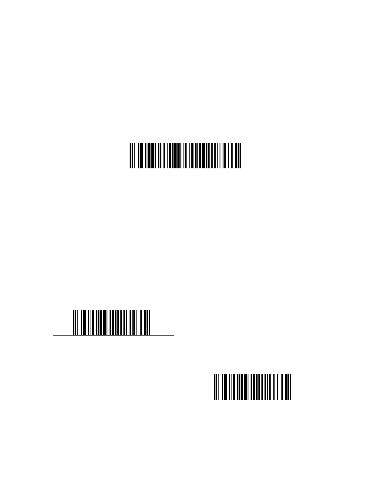
Snapshot Mode Timeout
Snapshot Aiming Pattern
Select Enable Snapshot Aiming Pattern to project the aiming pattern when in
Snapshot Mode, or Disable Snapshot Aiming Pattern to turn the aiming pattern
off.
Enable Snapshot Aiming Pattern
Disable Snapshot Aiming Pattern
Page 21
18
Image Cropping
This parameter crops a captured imag e. If Disable Im age Cro pping is sele cted,
the full 640 x 480 pixels are presented. If Enable is selected, the de coder crops
the image to the pixel addresses set in Crop to Pixel Addresses.
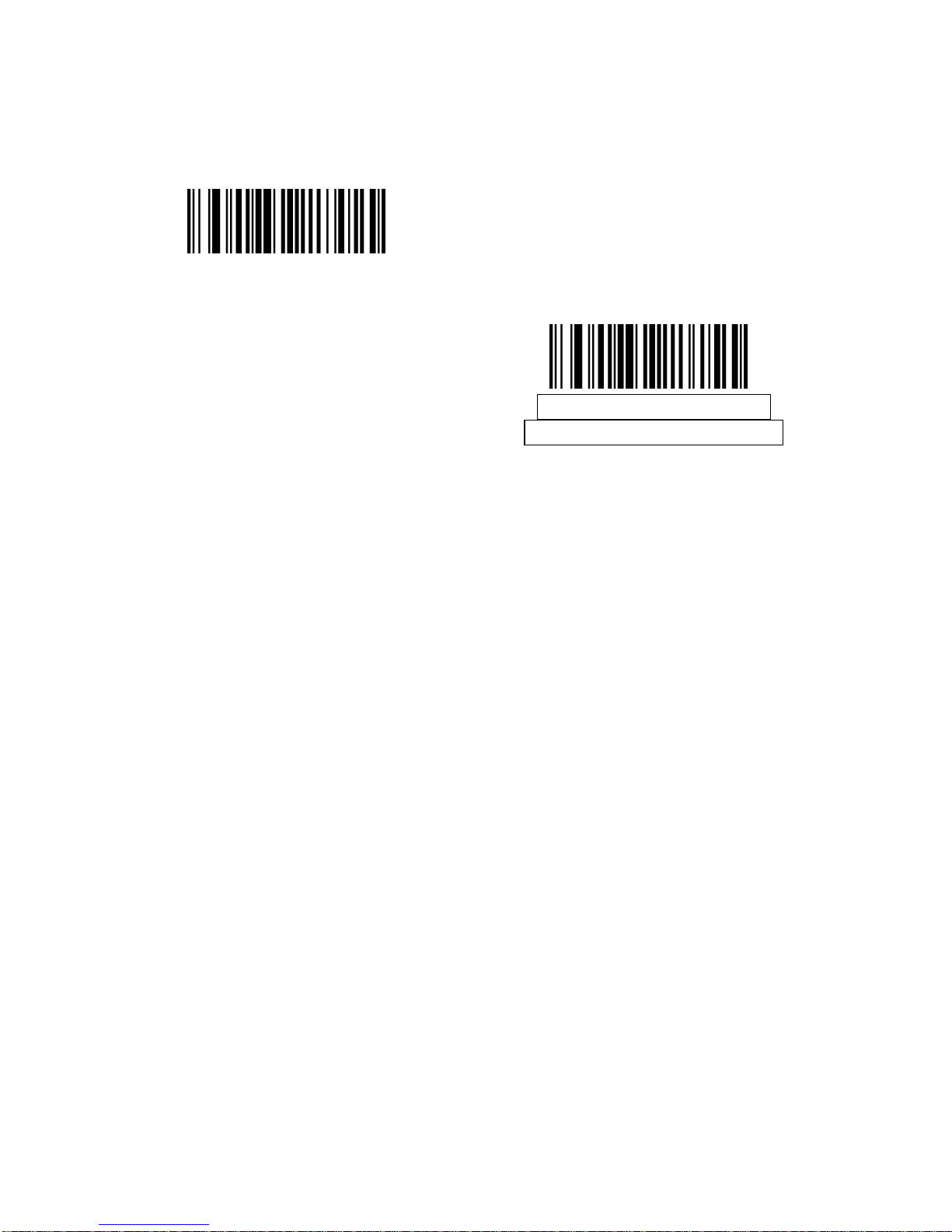
Enable Image Cropping
Disable Image Cropping
(Use Full 640 x 480 Pixels)
Page 22
19
Crop to Pixel Addresses
If Enable Image Cropping is selected, set the pixel addresses from (0, 0) to
(639,479) to crop to.
Columns are numbered from 0 to 639, rows from 0 to 479. Specify four values
for Top, Left, Bottom, and Right, where Top and Bottom correspond to row
pixel addresses, and Left and Right correspond to column pixel ad dre sses. Fo r
example, for a 4 row x 8 column image in the extreme bottom-right section of
the image set the following values:
Top = 476, Bottom = 479, Left = 632, Right = 639
To set the pixel address to crop to, scan each Pixel Address bar code followed
by three bar codes from Appendix D, Numeric Bar Codes which represent the
value. Leading zeros are required, so to enter a value of 3, for example, scan 0,
0, 3.
Top Pixel Address
(Default: 0)
(0 - 479 Decimal)
Left Pixel Address
(Default: 0)
(0 - 639 Decimal)
Bottom Pixel Address
(Default: 479)
(0 - 479 Decimal)
Right Pixel Address
(Default: 639)
(0 - 639 Decimal)
Page 23
20
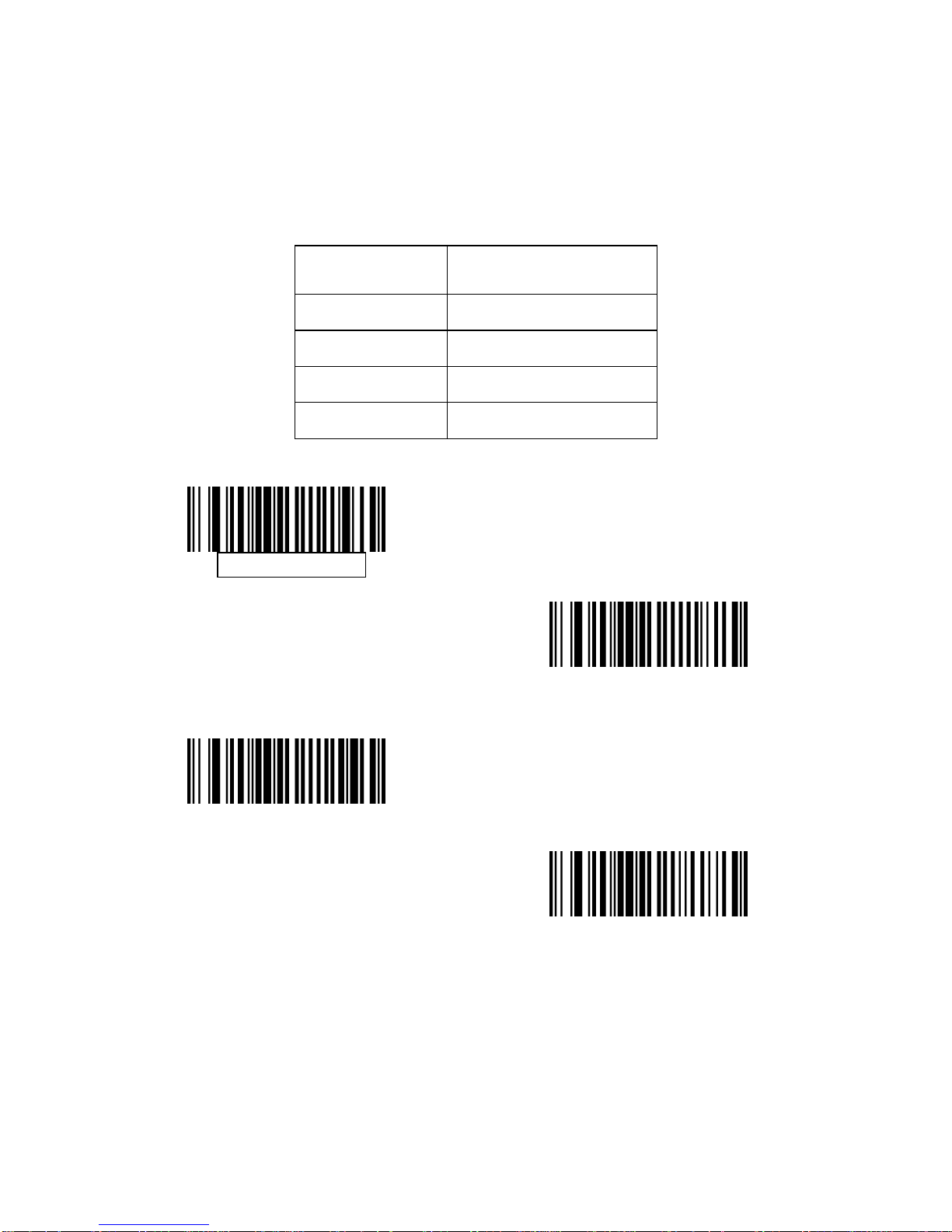
Image Resolution
This option alters image resolution before compression. Multiple pixels are
combined to one pixel, resulting in a smaller image containing the original
content with reduced resolution.
Select one of the following values:
Resolution
Value
Uncropped Image
Size
Full 640 x 480
1/2 320 x 240
1/3 212 x 160
1/4 160 x 120
Full Resolution
1/3 Resolution
1/2 Resolution
1/4 Resolution
Page 24
21
JPEG Image Options
JPEG images can be optimized for either size or for quality. Scan the Quality
Selector bar code to enter a quality value; the decoder then selects the
corresponding image size. Scan the Size Selector bar code to enter a size
value; the decoder then selects the best image quality.
JPEG Quality Selector
JPEG Size Selector
JPEG Quality and Size Value
If JPEG Quality Selector is selected, scan the JPEG Quality Value bar code
followed by 3 bar codes from Appendix D, Numeric Bar Codes corresponding
to a value from 5 to 100, where 100 represents the highest quality image.
If JPEG Size Selector is selected, scan JPEG Size Value followed by 3 bar
codes from Appendix D, Numeric Bar Codes corresponding to a value from 5
to 150 which represent the file size in multiples of 1024 bytes (1K). For
example, setting this value to 8 (008) permits the file size to be as large as
8192 bytes.
JPEG Quality Value
(Default: 065)
(5 - 100 Decimal)
JPEG Size Value
(Default: 040)
(5 - 150 Decimal)
Page 25
22
Image File Format Selector
Select an image format appropriate for the system (BMP, TIFF, or JPEG). The
decoder stores captured images in the selected format.
BMP File Format
JPEG File Format
TIFF File Format
Bits per Pixel
Select the number of significant bits per pixel (BPP) to use when capturing an
image. Select 1BPP for a black and white image, 4BPP to assign 1 of 16 levels
of grey to each pixel, or 8BPP to assign 1 of 256 levels of grey to each pixel.
The decoder ignores these settings for JPEG files, which always use 8BPP.
1 BPP
4 BPP
8 BPP
Page 26
23
Signature Capture
A signature capture bar code is a special-purpose symbology which delineates
a signature capture area in a document with a machine-readable format. The
recognition pattern is variable so it can optionally provide an index to various
signatures. The region inside the bar code pattern is considered the signature
capture area.
Output File Format
Decoding a signature capture bar code de-skews the signature image converts
the image to a BMP, JPEG, or TIFF file format. The output data includes the
file descriptor followed by the formatted signature image.
File Descriptor
Output Format
(1 byte)
Signature Type
(1 byte)
Signature Image
Size (4 bytes)
(BIG Endian)
Signature Image
JPEG - 1
BMP - 3 1-8 0x00000400 0x00010203…..
TIFF - 4
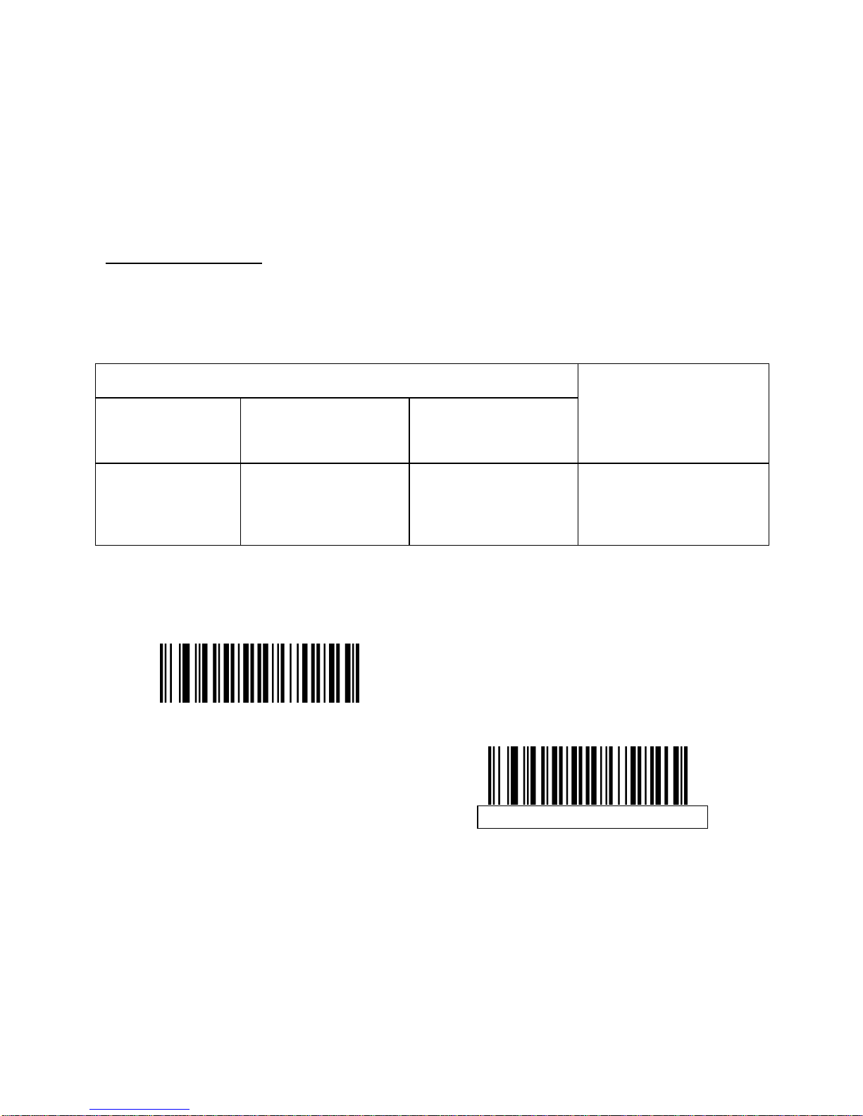
To enable or disable Signature Capture, scan the appropriate bar code below.
Enable Signature Capture
Disable Signature Capture
Page 27
24
Signature Capture File Format Selector
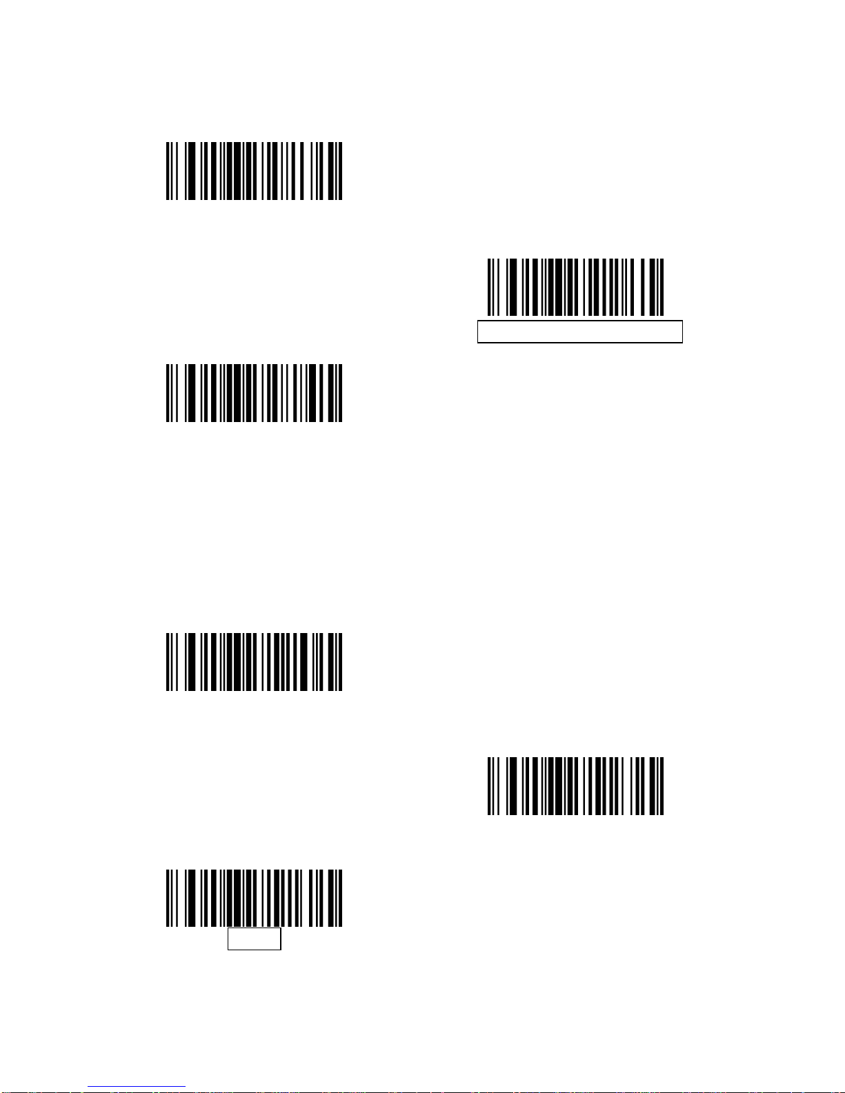
Select a signature file format appropriate for the system (BMP, TIFF, or JPEG).
The decoder stores captured signatures in the selected format.
BMP Signature Format
JPEG Signature Format
TIFF Signature Format
Signature Capture Bits per Pixel
Select the number of significant bits per pixel (BPP) to use when capturing a
signature. Select 1BPP for a black and white image, 4BPP to assign 1 of 16
levels of grey to each pixel, or 8BPP to assign 1 of 256 levels of grey to each
pixel. The decoder ignores these settings for JPEG files, which always use
8BPP.
1 BPP
4 BPP
8 BPP
Page 28
25
Signature Capture Width
The aspect ratio of the Signature Capture Width and Signature Capture Height
parameters must match that of the signature capture area. For example, a 4 x
1 inch signature capture area would require a 4 to 1 aspect ratio of width to
height.
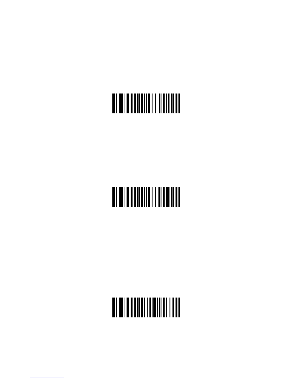
To set the width of the signature capture box, scan the Signature Capture
Width bar code, followed by 3 bar codes from Appendix D, Numeric Bar Codes
corresponding to a value in the range of 001 to 640 decimal.
Signature Capture Width
(Default: 400)
(001 - 640 Decimal)
Signature Capture Height
To set the height of the signature capture box, scan the Signature Capture
Height bar code, followed by 3 bar codes from Appendix D, Numeric Bar
Codes corresponding to a value in the range of 001 to 480 decimal.
Signature Capture Height
(Default: 100)
(001 - 480 Decimal)
Signature Capture JPEG Quality
Scan the JPEG Quality Value bar code followed by 3 bar codes from Appendix
D, Numeric Bar Codes corresponding to a value from 005 to 100, where 100
represents the highest quality image.
JPEG Quality Value
(Default: 065)
(5 - 100 Decimal)
Page 29
26
Video View Finder
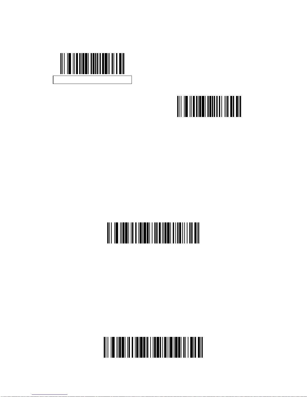
Select Enable Video View Finder to project the video view finder while in Imag e
Mode, or Disable Video View Finder to turn the video view finder off.
Disable Video View Finder
Enable Video View Finder
Target Video Frame Size
Select the number of 100-byte blocks to be transmitted per second. Selecting a
smaller value allows more frames to be transmitted per second but reduces
video quality; selecting a larger value increases video quality but slows
transmission.
To set the Target Video Frame Size, scan the bar code below followed by two
bar codes from Appendix D, Numeric Bar Codes corresp onding to the 100-byte
value from 800 to 3300 bytes. For example, to select 1500 bytes, enter 1, 5. To
select 900 bytes, enter 0, 9.
Target Video Frame Size
Video View Finder Image Size
Select the number of 100-byte blocks. Values range from 800 to 3000 bytes.
Selecting a smaller value allows more frames to be transmitted per second;
selecting a larger value increases video quality.
To set the Video View Finder Imager Size, scan the bar code belo w followed by
two bar codes from Appendix D, Numeric Bar Codes corresponding to the
100-byte value from 800 to 3000 bytes. For example, to select 1500 bytes,
enter 1, 5. To select 900 bytes, enter 0, 9.
Page 30

27
Serial Interface
Introduction
This chapter describes how to set up the decoder with a serial host. The serial
interface is used to connect the decoder to point-of sale devices, host
computers, or other devices with an available serial port (e.g. com port).
Note: The decoder uses TTL signal levels, which interface with most system
architectures. System architectures that use RS-232C signal levels require a
conversion circuitry.
The serial host type requires proper configuration of the sysconfig lines, and
typically require scanning bar code menus as part of initial configurat ion.
Most computer monitors allow scanning the bar codes directly on the screen.
When scanning from the screen is sure to set the document magnification to a
level where the bar code can be seen clearly, and bars and/or spaces are not
merging.
Page 31
28
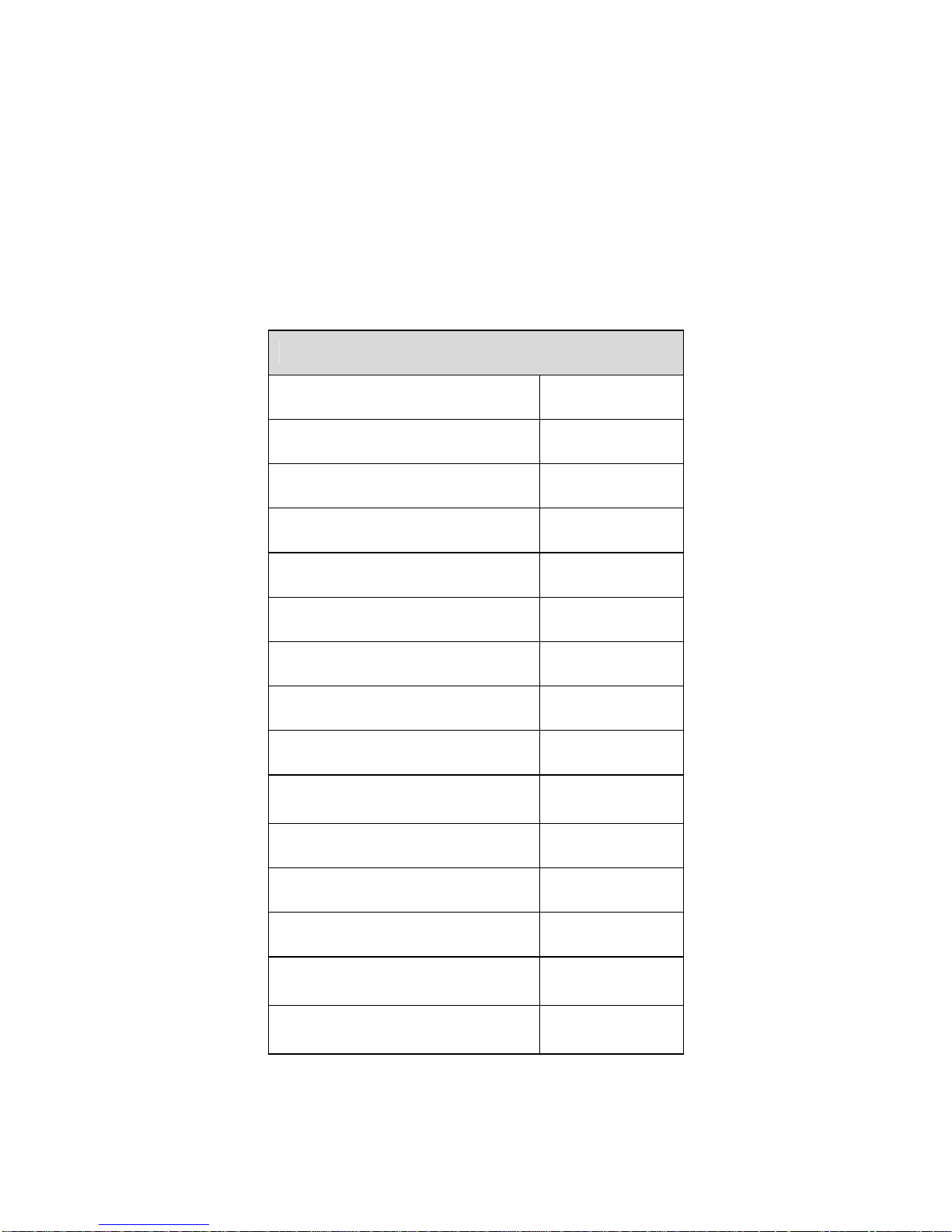
Serial Parameter Defaults
The table below lists the defaults for serial host parameters. To change any
option, scan the appropriate bar code(s) provided in the Serial Host
Parameters section.
Note: See Appendix A, Standard Default Parameters for all user preferences,
hosts, symbologies, and miscellaneous default parameters.
Serial Host Default Table
Serial Host Parameters
Parameter Default
Serial Host Types Standard
Baud Rate 9600
Parity Type None
Stop Bit Select 1 Stop Bit
Data Bits 8-Bit
Check Receive Errors Enable
Hardware Handshaking None
Software Handshaking None
Host Serial Response
Time-out
2 Sec
RTS Line State Low RTS
Beep on <BEL> Disable
Intercharacter Delay 0 msec
Nixdorf Beep/LED Options
Normal
Operation
Ignore Unknown
Characters
Send Bar
Code
Page 32
29
Serial Host Parameters
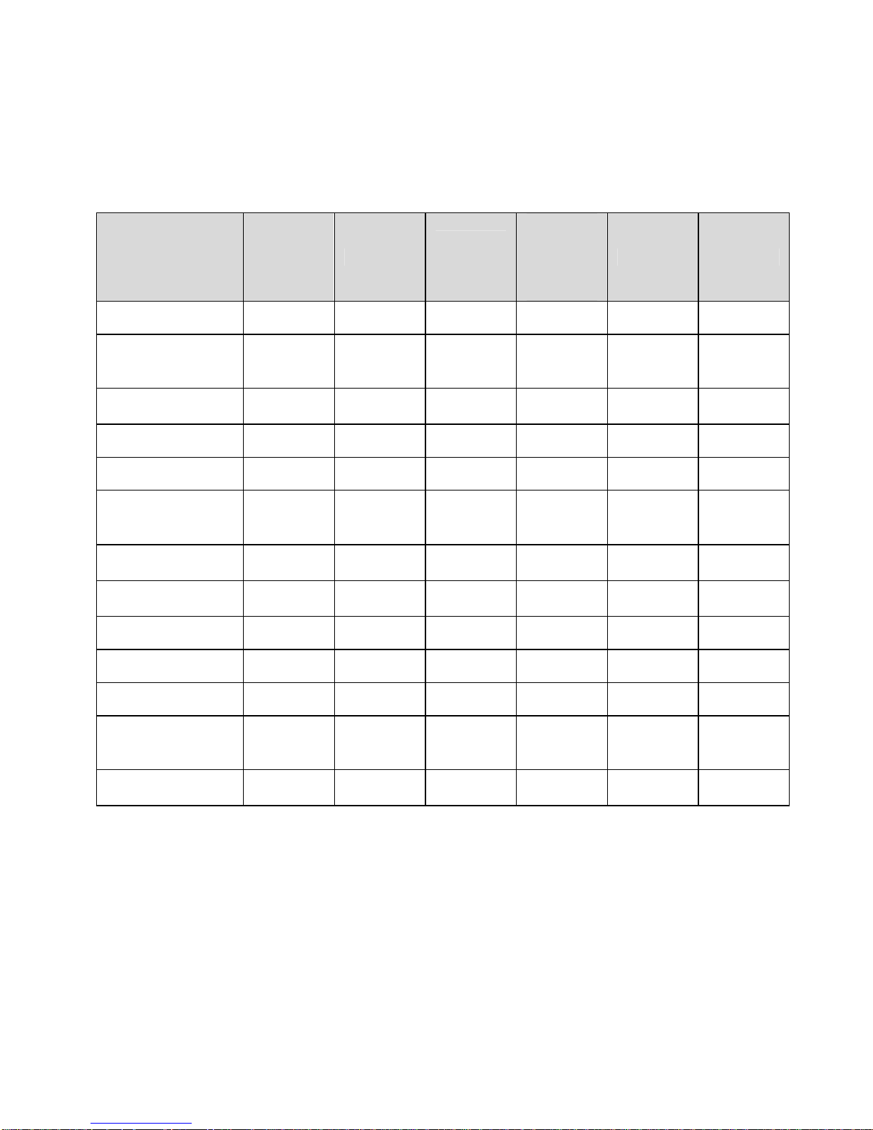
Various serial hosts are set up with their own parameter default settings as
indicated in table below. Selecting standard, ICL, Fujitsu, Wincor-Nixdorf Mode
A, Wincor-Nixdorf Mode B, OPOS/JPOS, Olivetti, or Omron sets the defaults
listed below.
Terminal Specific Serial
Parameter ICL Fujitsu
Wincor-
Nixdorf
Mode A
Wincor-
Nixdorf
Mode
B/OPOS/
JPOS
Olivetti Omron
Transmit Code ID Yes Yes Yes Yes Yes Yes
Data Transmission
Format
Data/
Suffix
Data/
Suffix
Data/
Suffix
Data/
Suffix
Prefix/
Data/
Suffix
Data/
Suffix
Suffix CR (1013) CR (1013) CR (1013) CR (1013) ETX
(1002)
CR (1013)
Baud Rate 9600 9600 9600 9600 9600 9600
Parity Even None Odd Odd Even None
Hardware
Handshaking
RTS/CTS
Option 3
None RTS/CTS
Option 3
RTS/CTS
Option 3
None None
Software
Handshaking
None None None None Ack/Nak None
Serial Response
Time-out
9.9 Sec. 2 Sec. 9.9 Sec. 9.9 Sec. 9.9 Sec. 9.9 Sec.
Stop Bit Select One One One One One One
ASCII Format 8-Bit 8-Bit 8-Bit 8-Bit 7-Bit 8-Bit
Beep On <BEL> Disable Disable Disable Disable Disable Disable
RTS Line State High Low Low Low = No
data to
send
Low High
Prefix None None None None STX
(1003)
None
*In the Nixdorf Mode B, if CTS is Low, scanning is disabled. When CTS is High, the user can scan
bar codes.
**If Nixdorf Mode B is scanned without the decoder connected to the proper host, it may appear
unable to scan. If this happens, scan a different serial host type within 5 seconds of cycling power
to the decoder.
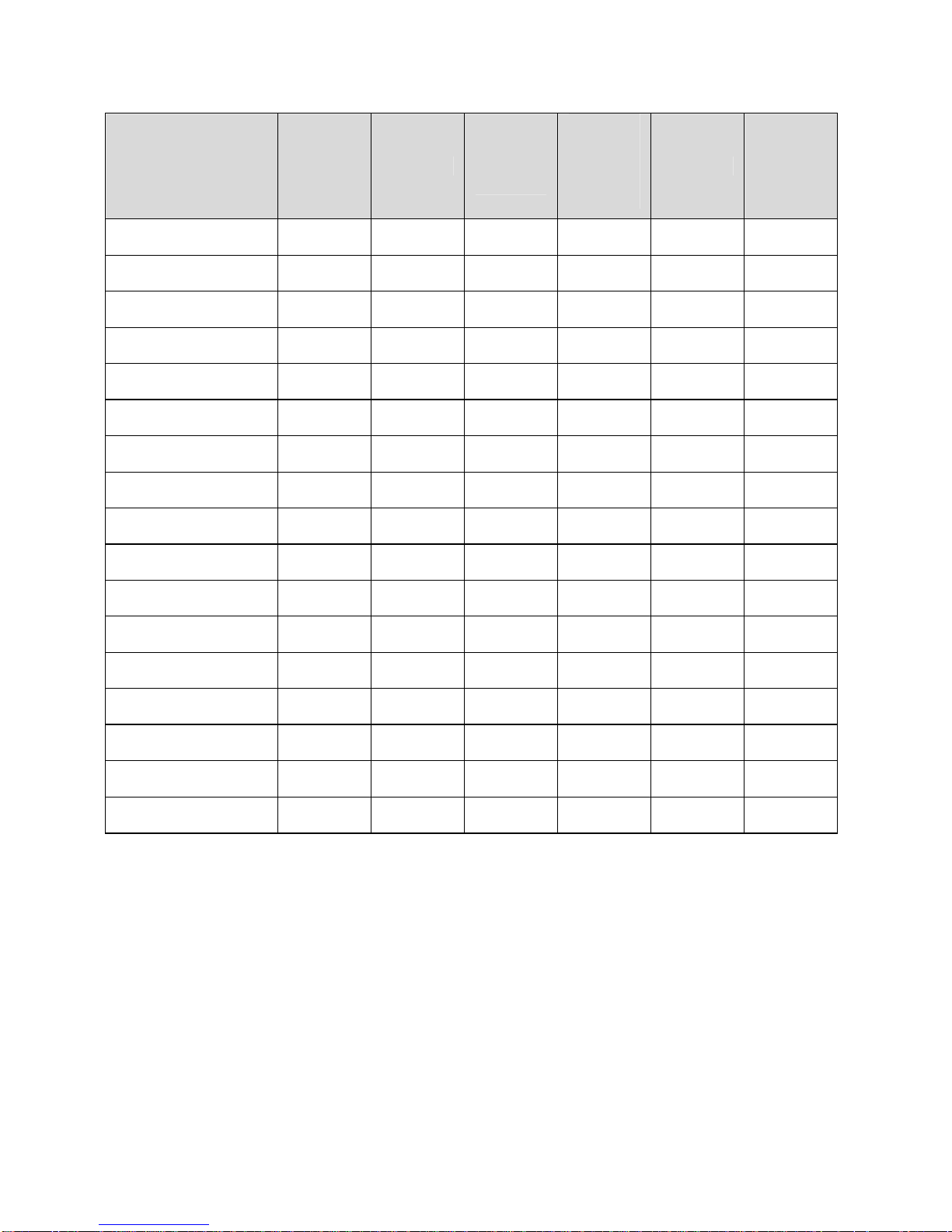
Selecting ICL, Fujitsu, Wincor-Nixdorf Mode A, Wincor-Nixdorf Mode B, OPOS/JPOS, Olivetti, or
Omron enables the transmission of code ID characters listed in table below. These code ID
characters are not programmable and are separate from the Transmit Code ID feature. Do not
enable the Transmit Code ID feature for these terminals.
Page 33
30
Terminal Specific Code ID Characters
Barcode Type ICL Fujitsu
WincorNixdorf
Mode A
Wincor-
Nixdorf
Mode B/
OPOS/
JPOS
Olivetti Omron
UPC-A A A A A A A
UPC-E E E C C C E
EAN-8/JAN-8 FF FF B B B FF
EAN-13/JAN-13 F F A A A F
Code 39 C <len> None M M M <len> C <len>
Codabar N <len> None N N N <len> N <len>
Code 128 L <len> None K K K <len> L <len>
I 2 of 5 I <len> None I I I <len> I <len>
Code 93 None None L L L <len> None
D 2 of 5 H <len> None H H H <len> H <len>
UCC/EAN 128 L <len> None P P P <len> L <len>
MSI None None O O O <len> None
Bookland EAN F F A A A F
Trioptic None None None None None None
Code 11 None None None None None None
IATA H<len> None H H None None
Code 32 None None None None None None
Page 34
31
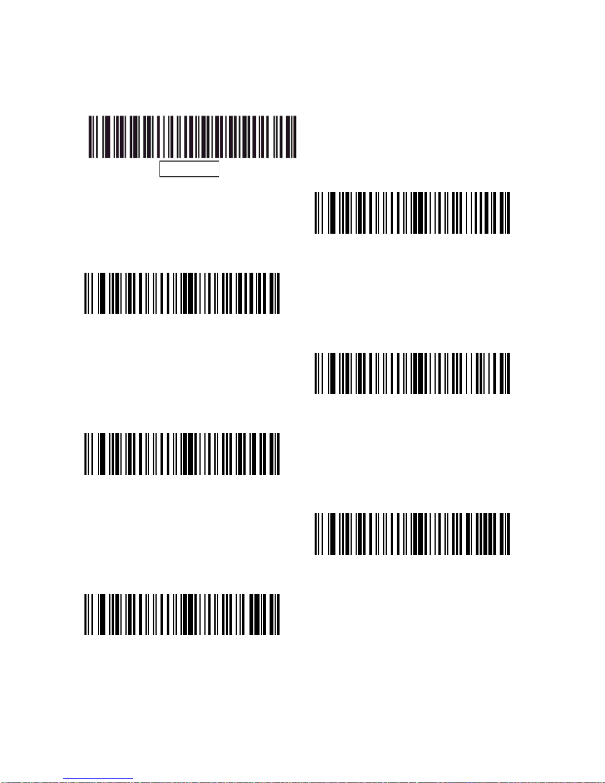
Serial Host Types
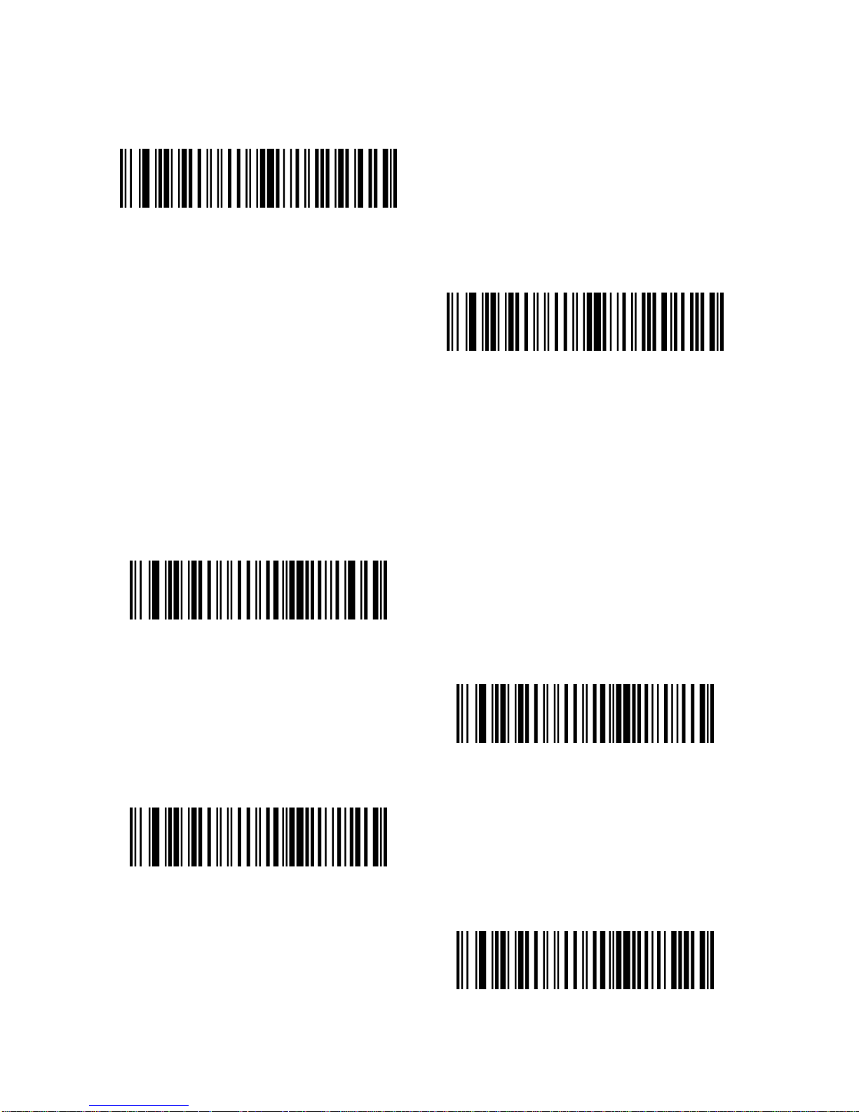
To select a serial host interface, scan one of the following bar codes.
SSI Host
Enable Serial Host (No Variant)
ICL Serial
Wincor-Nixdorf Serial Mode A
Wincor-Nixdorf Serial Mode B
Olivetti ORS4500
Omron
Page 35
32
*Scanning Enable Serial Host (No Variant) activates the serial driver, but does
not change port settings (e.g., parity, data bits, handshaking). Selecting
another serial host type bar code changes these settings.
OPOS/JPOS
Fujitsu Serial
Baud Rate
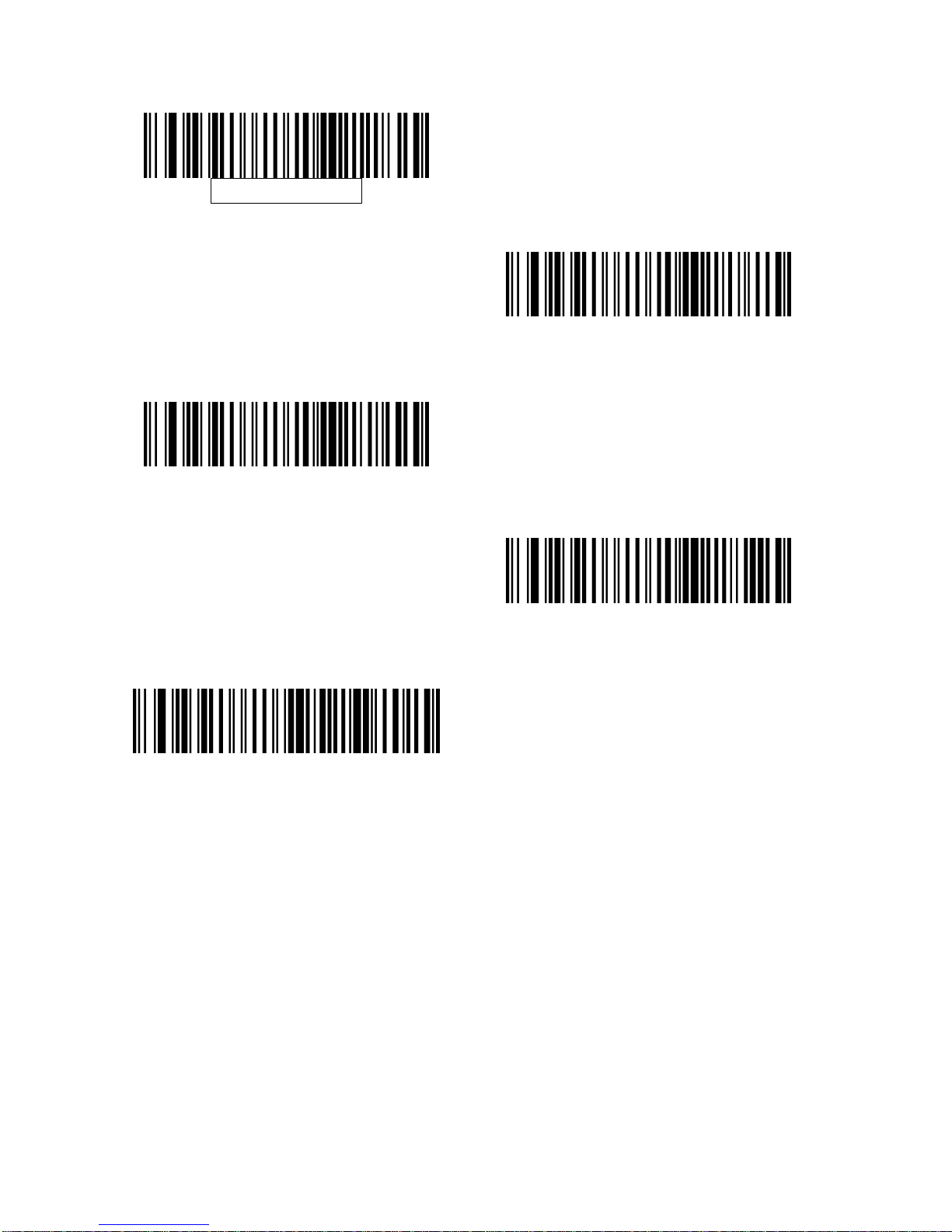
Baud rate is the number of bits of data transmitted per second. Set the
decoder's baud rate to match the baud rate setting of the host device.
Otherwise, data may not reach the host device or may reach it in distorted
form.
Baud Rate 600
Baud Rate 1200
Baud Rate 2400
Baud Rate 4800
Page 36
33
Baud Rate 9600
Baud Rate 19,200
Baud Rate 38,400
Baud Rate 57,600
Baud Rate 115,200
Page 37
34
Parity
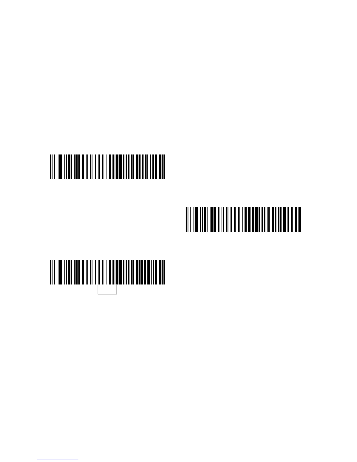
A parity check bit is the most significant bit of each ASCII coded character.
Select the parity type according to host device requirements.
Select Odd parity and the parity bit value is set to 0 or 1, based on data,
to ensure that an odd number of 1 bits are contained in the coded characte r.
Select Even parity and the parity bit value is set to 0 or 1, based on data,
to ensure that an even number of 1 bits are contained in the coded character.
Select None when no parity bit is required.
Odd
Even
None
Page 38
35
Stop Bit Select
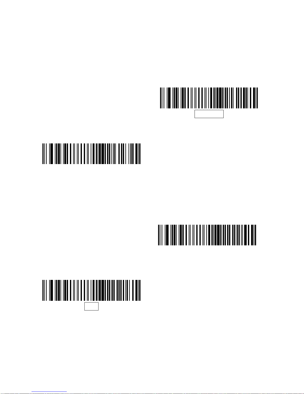
The stop bit(s) at the end of each transmitted character marks the end of
transmission of one character and prepares the receiving device for the next
character in the serial data stream. The number of stop bits selected (one or
two) depends on the number the receiving terminal is programmed to
accommodate. Set the number of stop bits to match host device requirements.
1 Stop Bit
2 Stop Bits
Data Bits
This parameter allows the decoder to interface with devices requiring a 7-bit or
8-bit ASCII protocol.
7-Bit
8-Bit
Page 39
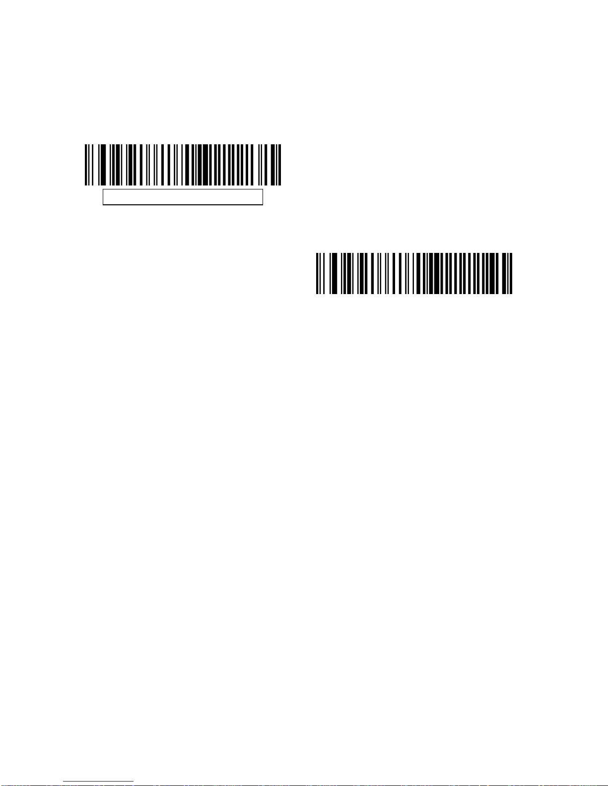
36
Check Receive Errors
Select whether or not the parity, framing, and overrun of received characters
are checked. The parity value of received characters is verified against the
parity parameter selected above.
Check For Received Errors
Do Not Check For Received Errors
Page 40

37
Hardware Handshaking
The data interface consists of a serial port designed to operate either with or
without the hardware handshaking lines, Request to Send (RTS), and Clear to
Send (CTS).
If Standard RTS/CTS handshaking is not selected, scan data is transmitted as
it becomes available. If Standard RTS/CTS handshaking is selected, scan d ata
is transmitted according to the following sequence:
The decoder reads the CTS line for activity. If CTS is asserted, the
decoder waits up to Host Serial Response Time-out for the host to
de-assert the CTS line. If, after Host Serial Response Time-out
(default), the CTS line is still asserted, the decoder sounds a
transmit error, and any scanned data is lost.
When the CTS line is de-asserted, the decoder asserts the RTS
line and waits up to Host Serial Response Time-out for the host to
assert CTS. When the host asserts CTS, data is transmitted. If,
after Host Serial Response Time-out (default), the CTS line is not
asserted, the decoder sounds a transmit error, and discards the
data.
When data transmission is complete, the decoder de-asserts RTS
10 msec after sending the last character.
The host should respond by negating CTS. The de co der che cks fo r
a de-asserted CTS upon the next transmission of data.
During the transmission of data, the CTS line should be asserted. If CTS is
deasserted for more than 50 ms between characters, the transmission is
aborted, the decoder sounds a transmission error, and the data is discarded. If
the above communication sequence fails, the decoder issues an error
indication. In this case, the data is lost and must be rescanned. If Hardware
Handshaking and Software Handshaking are both enabled, Hardware
Handshaking takes precedence.
Note: The DTR signal is jumpered to the active state.
None: Scan the bar code below if no Hardware Handshaking is
desired.
Standard RTS/CTS: Scan the bar code below to select Standard
RTS/CTS Hardware Handshaking.
RTS/CTS Option 1: When RTS/CTS Option 1 is selected, the
decoder asserts RTS before transmitting and ignores the state of
CTS. The decoder de-asserts RTS when the transmission is
complete.
RTS/CTS Option 2: When Option 2 is selected, RTS is always high
or low (user-programmed logic level). However, the decoder waits
for CTS to be asserted before transmitting data. If CTS is not
asserted within Host Serial Response Time-out (default), the
Page 41
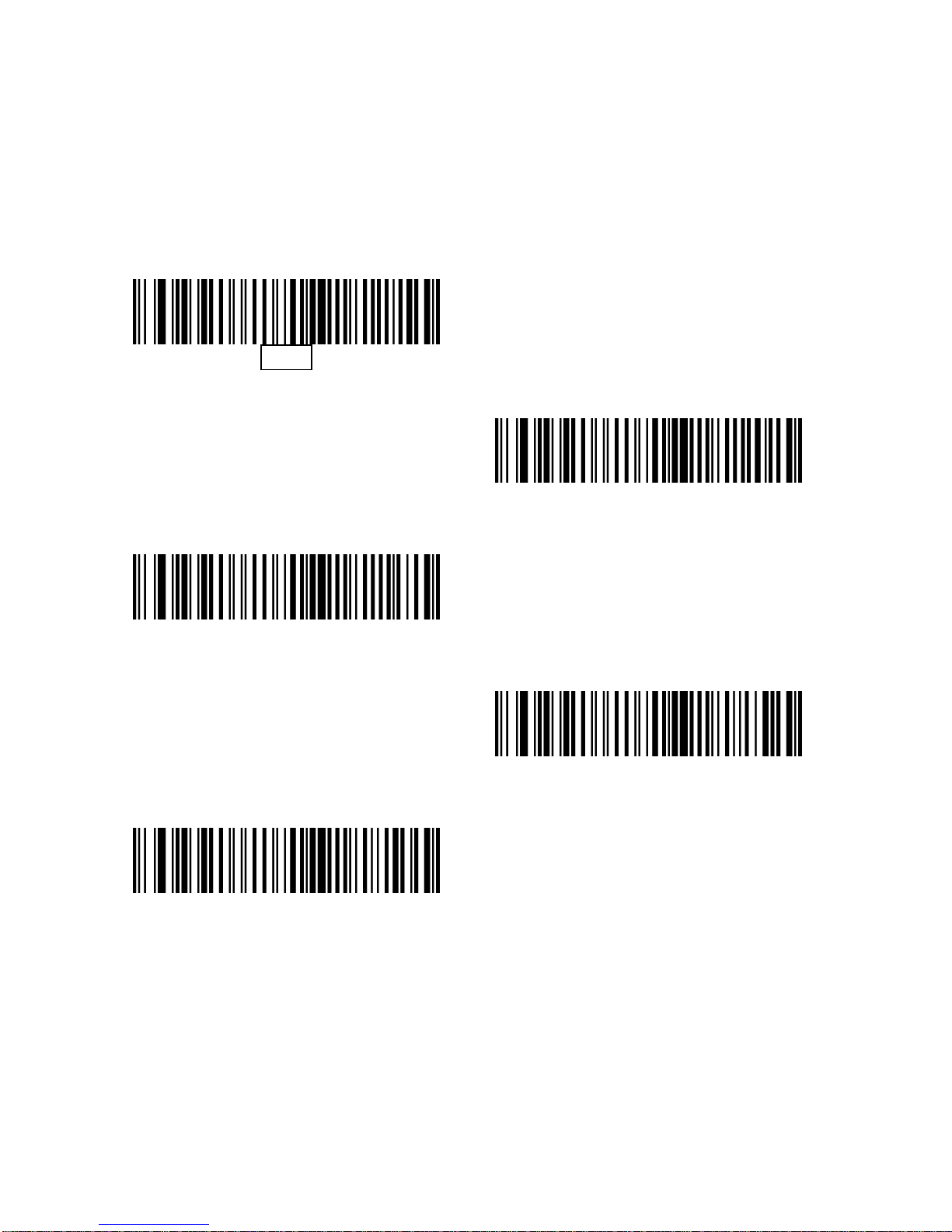
38
decoder issues an error indication and discards the data.
RTS/CTS Option 3: When Option 3 is selected, the decoder asserts
RTS prior to any data transmission, regardless of the state of CTS.
The decoder waits up to Host Serial Response Time-out (default)
for CTS to be asserted. If CTS is not asserted during this time, the
decoder issues an error indication and discards the data. The
decoder de-asserts RTS when transmission is com plete.
None
Standard RTS/CTS
RTS/CTS Option 1
RTS/CTS Option 2
RTS/CTS Option 3
Page 42

39
Software Handshaking
This parameter offers control of the data transmission pro cess i n a ddition to, or
instead of, that offered by hardware handshaking. There are five options.
If Software Handshaking and Hardware Han dshaking are both enabled,
Hardware Handshaking takes precedence.
None: When this option is selected, data is transmitted immediately.
No response is expected from host.
ACK/NAK: When this option is selected, after transmitting data, the
decoder expects either an ACK or NAK response from the host.
When a NAK is received, the decoder transmits the same data
again and waits for either an ACK or NAK. After three unsuccessful
attempts to send data when NAKs are received, the decoder issues
an error indication and discards the data.
The decoder waits up to the programmable Host Serial Response
Time-out to receive an ACK or NAK. If the decoder does not get a
response in this time, it issues an error indication and discards the
data. There are no retries when a time-out occurs.
ENQ: When this option is selected, the decoder waits for an ENQ
character from the host before transmitting data. If an ENQ is not
received within the Host Serial Response Time-out, the decoder
issues an error indication and discards the data. The host must
transmit an ENQ character at least every Host Serial Response
Time-out to prevent transmission errors.
ACK/NAK with ENQ: This combines the two previous options. For
re-transmissions of data, due to a NAK from the host, an additional
ENQ is not required.
• XON/XOFF: An XOFF character turns the decoder
transmission off until the decoder receives an XON character.
There are two situations for XON/XOFF:
XOFF is received before the decoder has data to send. When the
decoder has data to send, it waits up to Host Serial Response
Time-out for an XON character before transmission. If the XON is
not received within this time, the decoder issues an error indication
and discards the data.
XOFF is received during a transmission. Data transmission then
stops after sending the current byte. When the deco der receives an
XON character, it sends the rest of the data message. The decoder
waits indefinitely for the XON.
Page 43
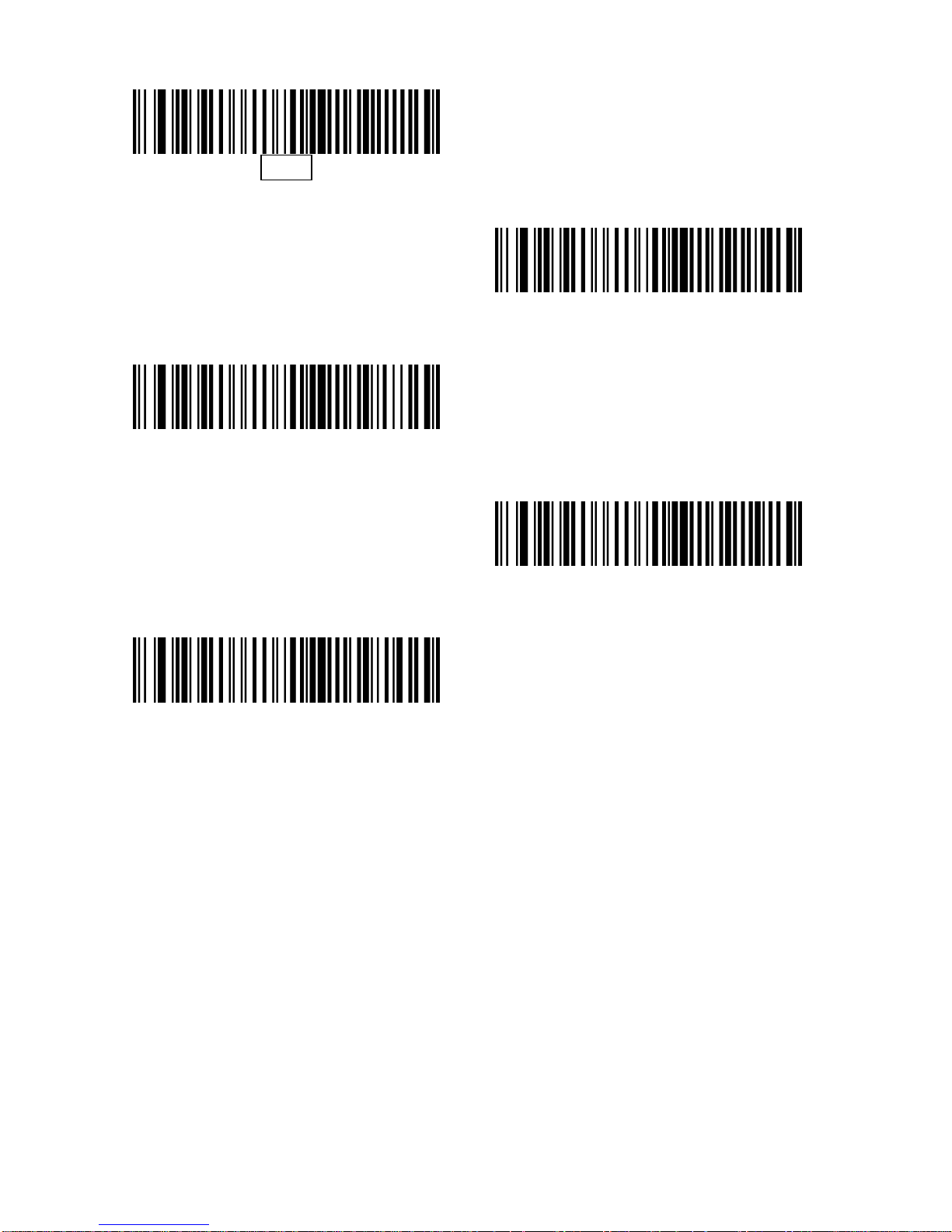
40
None
ACK/NAK
ENQ
ACK/NAK with ENQ
XON/XOFF
Page 44
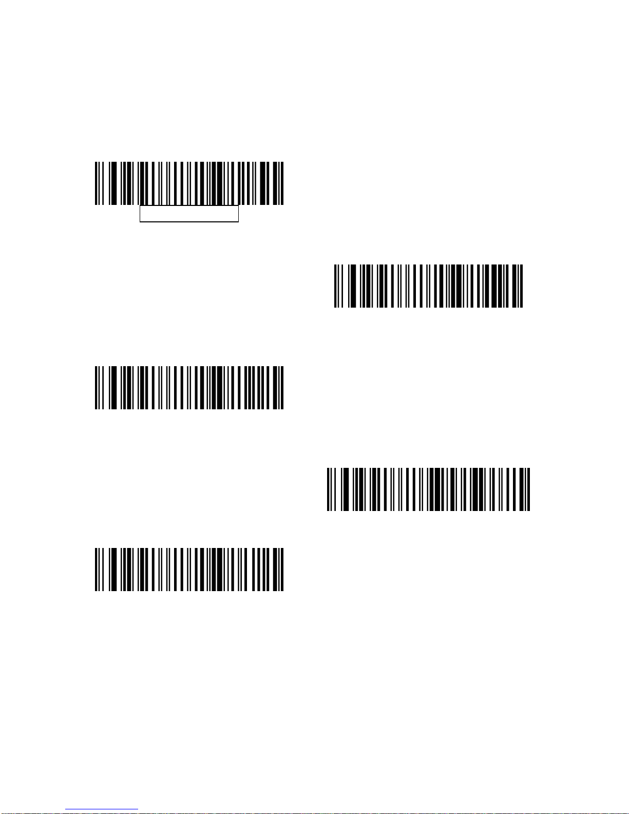
41
Host Serial Response Time-out
This parameter specifies how long the decoder waits for an ACK, NAK, or CTS
before determining that a transmission error has occurred. This only applies
when in one of the ACK/NAK Software Handshaking modes, or RTS/CTS
Hardware Handshaking option.
Minimum: 2 Sec
Low: 2.5 Sec
Medium: 5 Sec
High: 7.5 Sec
Maximum: 9.9 Sec
Page 45
42
RTS Line State
This parameter sets the idle state of the Serial Host RTS line. Scan a bar code
below to select Low RTS or High RTS line state.
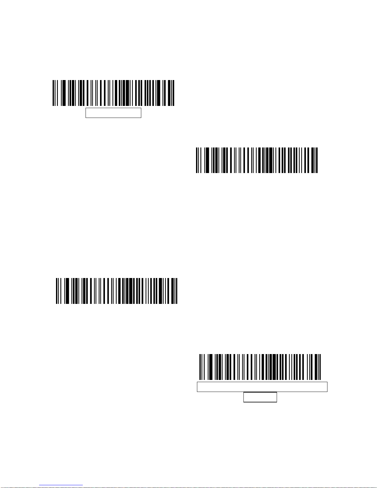
Host: Low RTS
Host: High RTS
Beep on <BEL>
When this parameter is enabled, the decoder issues a beep when a <BEL>
character is detected on the serial line. <BEL> is issued to gain a user's
attention to an illegal entry or other important event.
Beep On <BEL> Character
(Enable)
Do Not Beep On <BEL> Character
(Disable)
Note: A NULL character must be sent to the decoder before BEL to ensure the
BEL character is processed correctly.
Page 46
43
Intercharacter Delay
This parameter specifies the intercharacter delay inserted between character
transmissions.
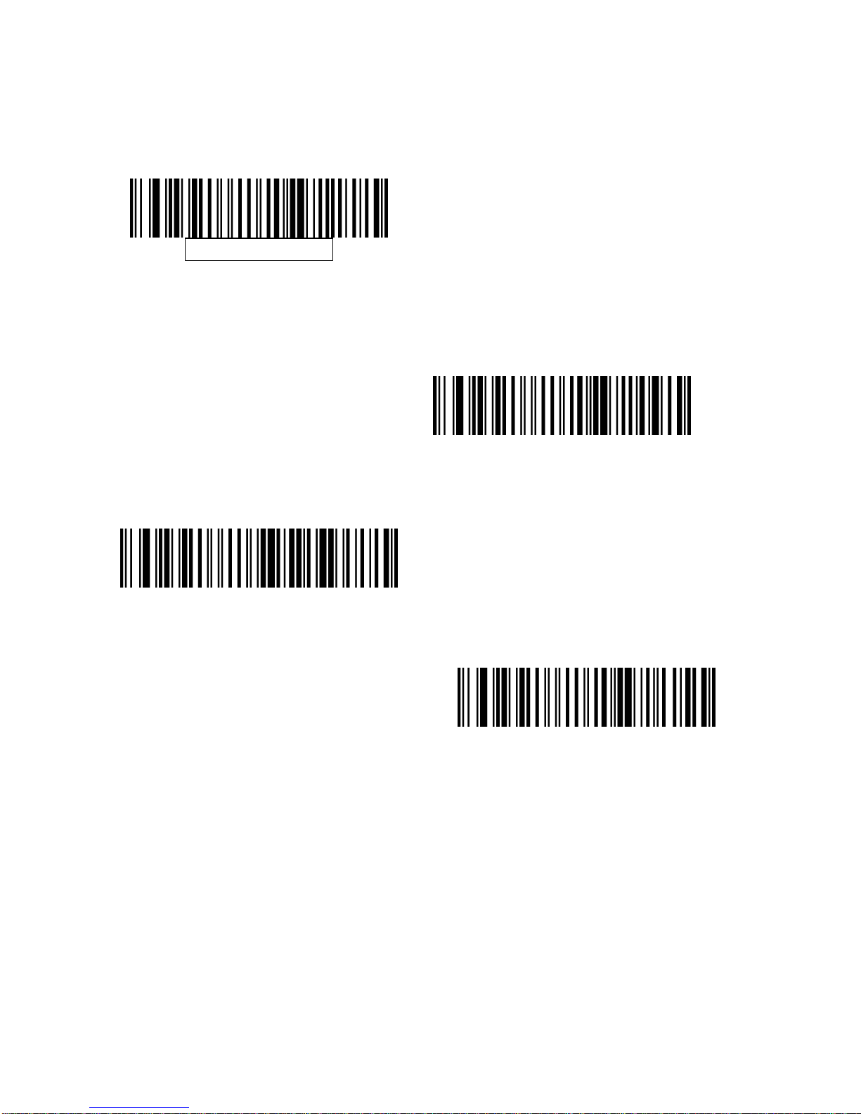
Minimum: 0 msec
Low: 25 msec
High: 75 msec
Maximum: 99 msec
Page 47
44
Nixdorf Beep/LED Options
When Nixdorf Mode B is selected, this indicates the decoder sho uld beep and
turn on its LED after a decode.
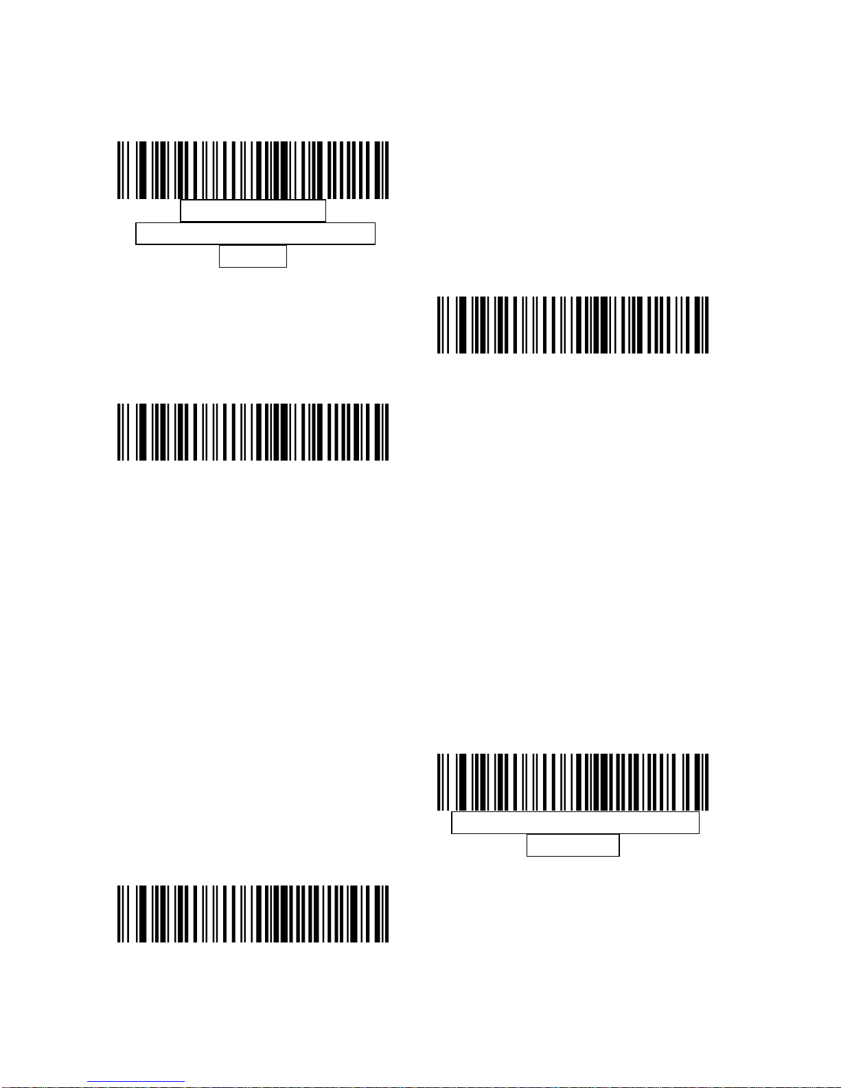
Normal Operation
(Beep/LED immediately after
decode)
Beep/LED After Transmission
Beep/LED After CTS Pulse
Ignore Unknown Characters
Unknown characters are characters the hos t does not recognize. When Send
Bar Codes with Unknown Characters is selected, all bar code data is sent
except for unknown characters, and no error beeps sound on the decoder.
When Do Not Send Bar Codes With Unknown Characters is selected, bar cod e
data is sent up to the first unknown character and then an error beep will sound
on the decoder.
Send Bar Code(with unknown
characters)
Do Not Send Bar Codes (with
unknown characters)
Page 48
45
ASCII Character Set for Serial Hosts
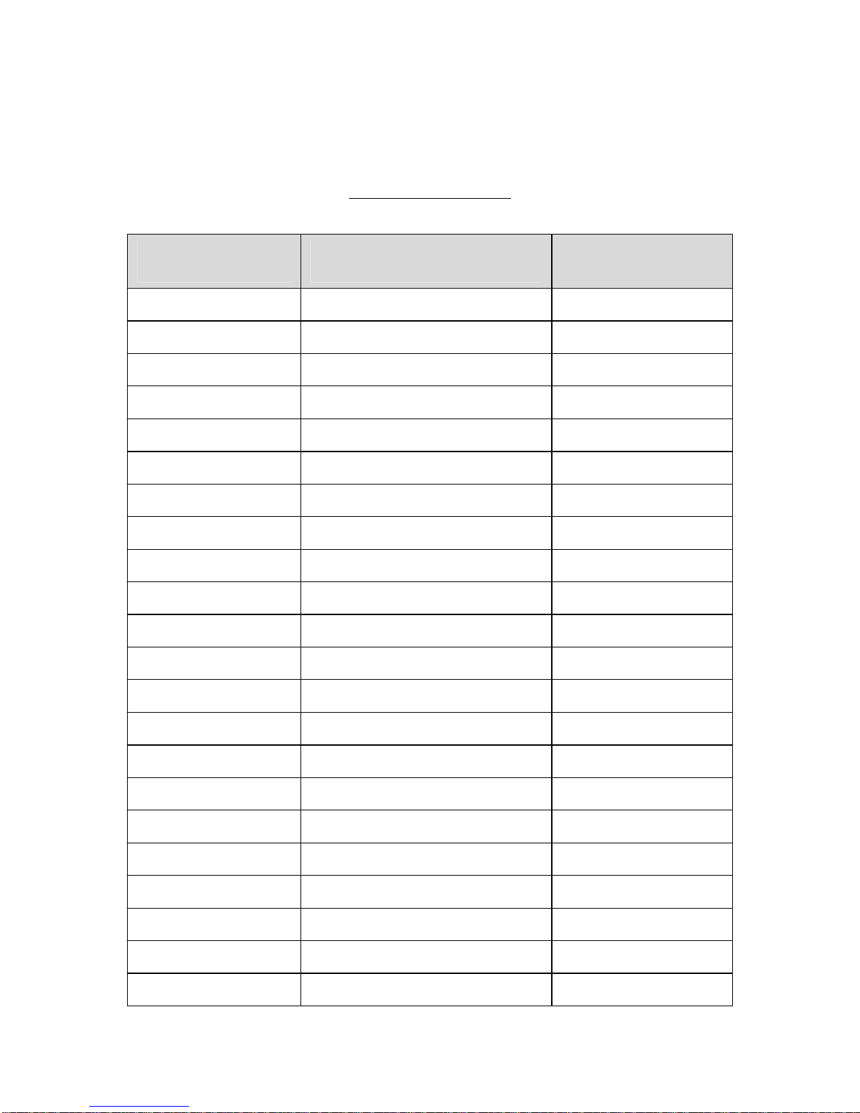
The values in the table below can be assign ed as prefixes or suffixes for ASCII
character data transmission.
Prefix/Suffix Values
Prefix/Suffix
Value
Full ASCII Code 39
Encode Character
ASCII Character
1000 %U NUL
1001 $A SOH
1002 $B STX
1003 $C ETX
1004 $D EOT
1005 $E ENQ
1006 $F ACK
1007 $G BELL
1008 $H BCKSPC
1009 $I HORIZ TAB
1010 $J LF/NW LN
1011 $K VT
1012 $L FF
1013 $M CR/ENTER
1014 $N SO
1015 $O SI
1016 $P DLE
1017 $Q DC1/XON
1018 $R DC2
1019 $S DC3/XOFF
1020 $T DC4
1021 $U NAK
Page 49

46
1022 $V SYN
1023 $W ETB
1024 $X CAN
1025 $Y EM
1026 $Z SUB
1027 %A ESC
1028 %B FS
1029 %C GS
1030 %D RS
1031 %E US
1032 Space Space
1033 /A !
1034 /B "
1035 /C #
1036 /D $
1037 /E %
1038 /F &
1039 /G ‘
1040 /H (
1041 /I )
1042 /J *
1043 /K +
1044 /L ,
1045 - 1046 . .
1047 /O /
1048 0 0
1049 1 1
1050 2 2
Page 50

47
1051 3 3
1052 4 4
1053 5 5
1054 6 6
1055 7 7
1056 8 8
1057 9 9
1058 /Z :
1059 %F ;
1060 %G <
1061 %H =
1062 %I >
1063 %J ?
1064 %V @
1065 A A
1066 B B
1067 C C
1068 D D
1069 E E
1070 F F
1071 G G
1072 H H
1073 I I
1074 J J
1075 K K
1076 L L
1077 M M
1078 N N
1079 O O
Page 51

48
1080 P P
1081 Q Q
1082 R R
1083 S S
1084 T T
1085 U U
1086 V V
1087 W W
1088 X X
1089 Y Y
1090 Z Z
1091 %K [
1092 %L \
1093 %M ]
1094 %N ^
1095 %O _
1096 %W `
1097 +A a
1098 +B b
1099 +C c
1100 +D d
1101 +E e
1102 +F f
1103 +G g
1104 +H h
1105 +I i
1106 +J j
1107 +K k
1108 +L l
Page 52

49
1109 +M m
1110 +N n
1111 +O o
1112 +P p
1113 +Q q
1114 +R r
1115 +S s
1116 +T t
1117 +U u
1118 +V v
1119 +W w
1120 +X x
1121 +Y y
1122 +Z z
1123 %P {
1124 %Q |
1125 %R }
1126 %S ~
1127 Undefined
7013 ENTER
Page 53
50
USB Interface
Introduction
This chapter describes how to set up the decoder with a USB host. The
decoder connects directly to a USB host, or a powered USB hub, and is
powered by it. No additional power supply is required.
Note: Most computer monitors allow scanning the bar codes directly on the
screen. When scanning from the screen, be sure to set the document
magnification to a level where the bar code can be seen clearly, and bars
and/or spaces are not merging.
USB Parameter Defaults
Table below lists the defaults for USB host parameters. To change any option,
scan the appropriate barcode(s) provided in the Parameter Descriptions
section.
Note: See Appendix A, Standard Default Parameters for all user preferences,
hosts, symbologies, and miscellaneous default parameters.
USB Host Default Table
USB Host Parameters
Parameters Default
USB Device Type HID Keyboard Emulation
Symbol Native API (SNAPI) Status Handshaking
Enable SNAPI Status
Handshaking
USB Country Keyboard Types (Country Codes) North American
USB Keystroke Delay No Delay
USB CAPS Lock Override Disable
USB Ignore Unknown Characters Enable
Emulate Keypad Disable
USB FN1 Substitution Disable
Function Key Mapping Disable
Simulated Caps Lock Disable
Convert Case No Case Conversion
Page 54
51
USB Host Parameters
USB Device Type
Select the desired USB device type.
Note: When changing USB Device Types, the decoder automatically resets.
The decoder issues the standard startup beep sequences.
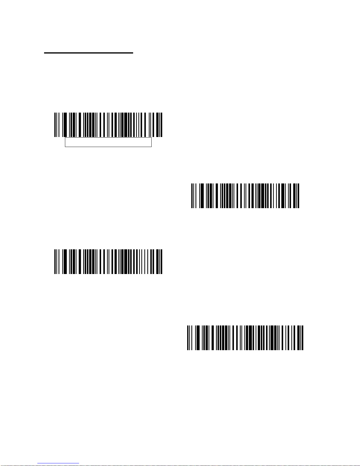
HID Keyboard Emulation
Simple COM Port Emulation
Symbol Native API (SNAPI) with
Imaging Interface
Symbol Native API (SNAPI) without
Imaging Interface
Page 55
52
Symbol Native API (SNAPI) Status Handshaking
After selecting a SNAPI interface as the USB device type, select whether to
enable or disable status handshaking.
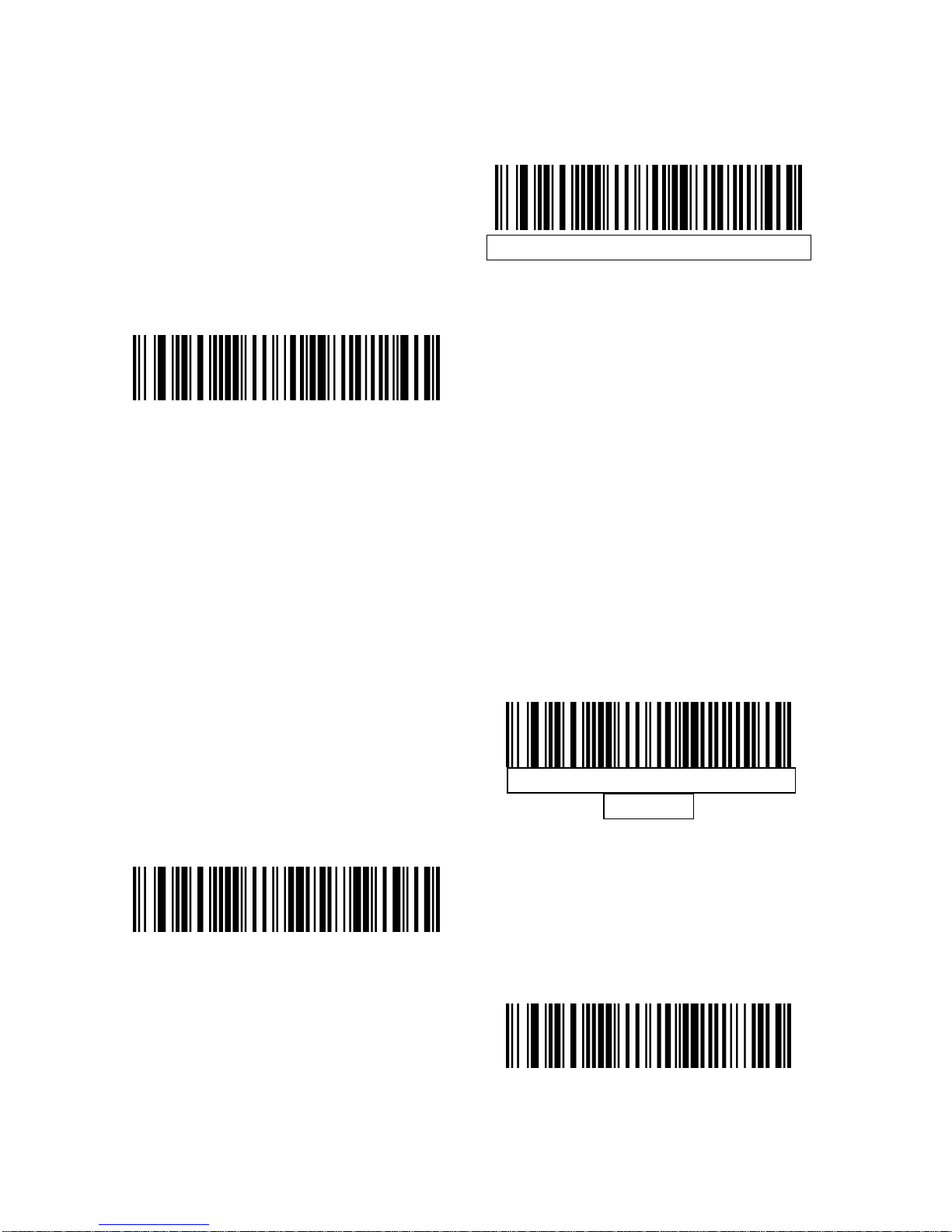
Enable SNAPI Status Handshaking
Disable SNAPI Status Handshaking
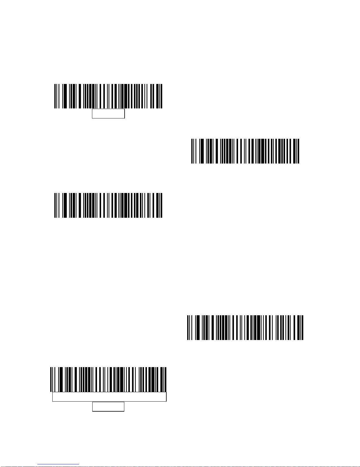
USB Country Keyboard Types (Country Codes)
Scan the bar code corresponding to the keyboard type. This setting applies
only to the USB HID Keyboard Emulation device.
Note: When changing USB country keyboard types the decoder automatically
resets. The decoder issues the standard startup beep sequences.
North American Standard USB
Keyboard
German Windows
French Windows
Page 56
53
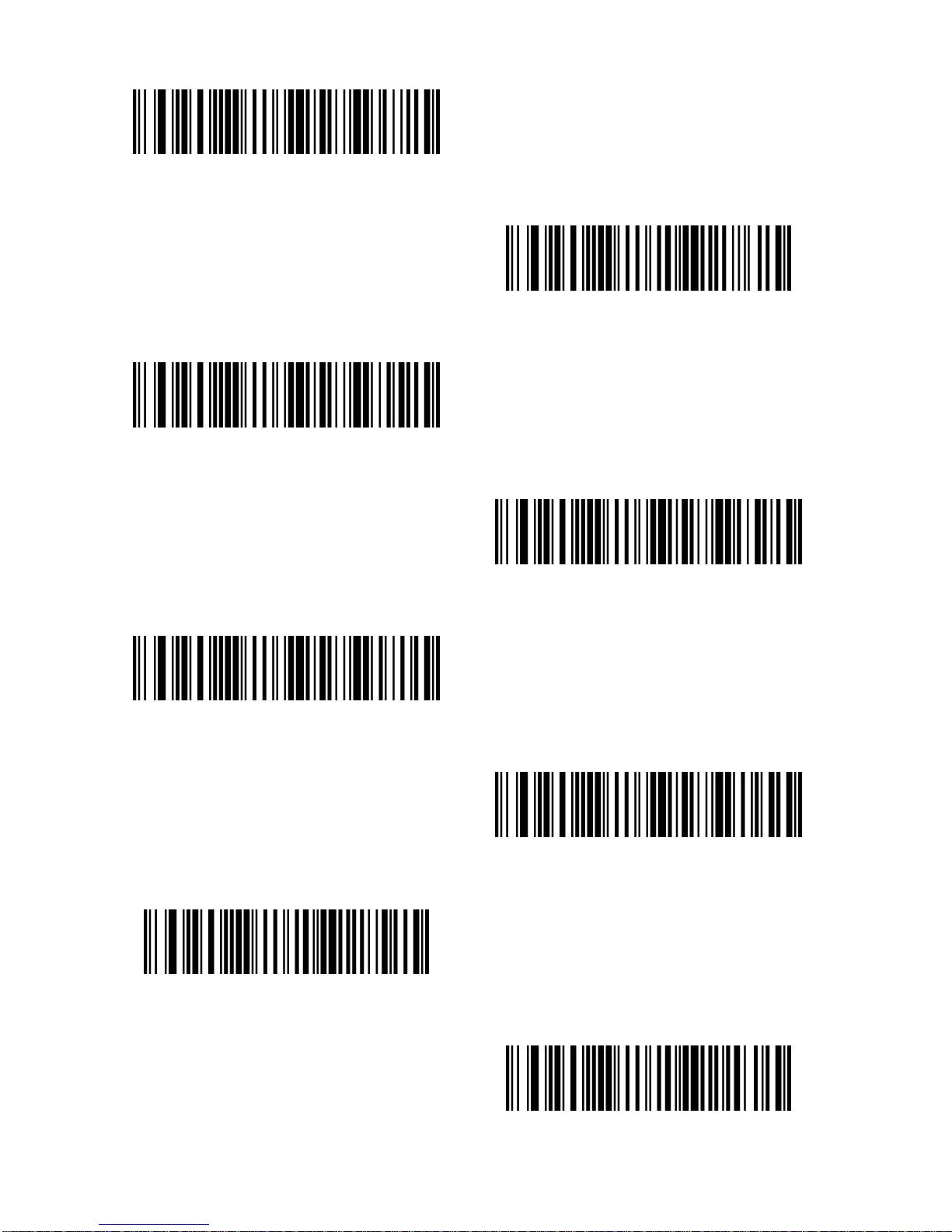
French Canadian Windows 2000/XP
French Canadian Windows 95/98
Spanish Windows
Italian Windows
Swedish Window
UK English Windows
Japanese Windows (ASCII)
Portuguese-Brazilian Windows
Page 57
54
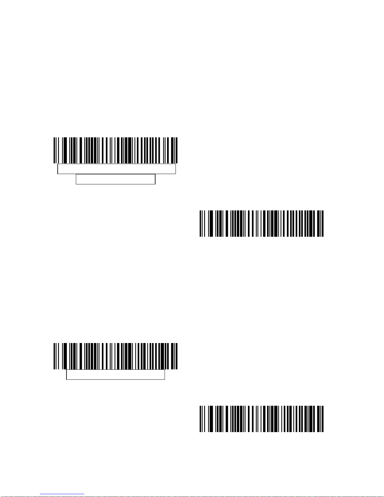
USB Keystroke Delay
This parameter sets the delay, in milliseconds, between emulated keystrokes.
Scan a bar code below to increase the delay when hosts require a slower
transmission of data.
No Delay
Medium Delay (20 msec)
Long Delay (40 msec)
USB CAPS Lock Override
This option applies only to the HID Keyboard Emulation device. When enabled,
the case of the data is preserved regardless of the state of the caps lock key.
This setting is always enabled for the Japanese, Windows (ASCII) keyboard
type and can not be disabled.
Override Caps Lock Key(Enable)
Do Not Override Caps Lock Key
(Disable)
Page 58
55
USB Ignore Unknown Characters
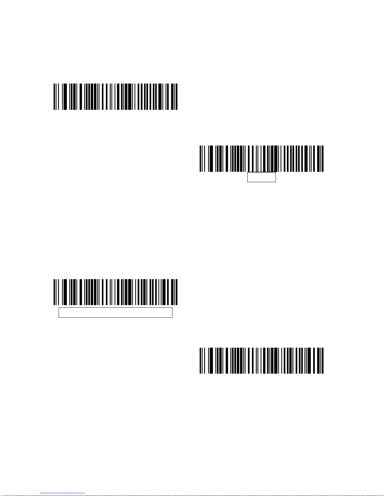
This option applies only to the HID Keyboard Emulation device and IBM device .
Unknown characters are characters the hos t does not recognize. When Send
Bar Codes With Unknown Characters is selected, all bar code data is sent
except for unknown characters, and no error beeps sound. When Do Not Send
Bar Codes With Unknown Characters is selected, for IBM devices, bar codes
containing at least one unknown character are not sent to the host, and an
error beep sounds. For HID Keyboard Emulation devices, the bar code
characters up to the unknown character are sent, and an error beep sounds.
Send Bar Codes with Unknown
Characters(Transmit)
Do Not Send Bar Codes with
Unknown Characters (Disable)
Emulate Keypad
When enabled, all characters are sent as ASCII sequences over the numeric
keypad. For example ASCII A would be sent as “ALT make” 0 6 5 “ALT Break”.
This allows support for other country variants.
Disable Keypad Emulation
Enable Keypad Emulation
Page 59
56
USB Keyboard FN 1 Substitution
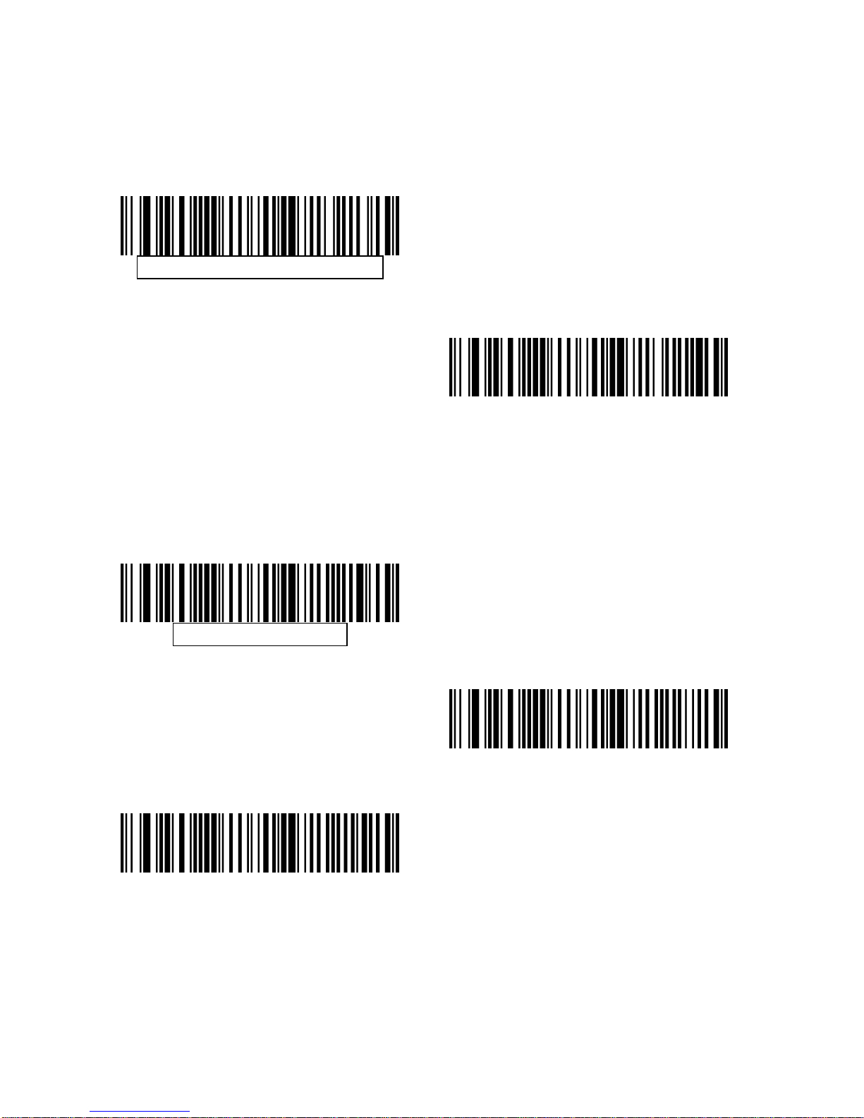
This option applies only to the USB HID Keyboard Emulation device. When
enabled, this allows replacement of any FN 1 characters in an EAN 128 bar
code with a Key Category and value chosen by the user.
Enable
Disable
Function Key Mapping
ASCII values under 32 are normally sent as a control-key se quence. When thi s
parameter is enabled, the keys in bold are sent in place of the standard key
mapping. Table entries that do not have a bold entry remain the same whether
or not this parameter is enabled.
Disable Function Key Mapping
Enable Function Key Mapping
Page 60
57
Simulated Caps Lock
When enabled, the decoder inverts uppe r and lower case characters on the b ar
code as if the Caps Lock state is enabled on the keyboard. This inversion is
done regardless of the current state of the keyboard’s Caps Lock state.
Disable Simulated Caps Lock
Enable Simulated Caps Lock
Convert Case
When enabled, the decoder converts all bar code data to the selected ca se.
No Case Conversion
Convert All to Upper Case
Convert All to Lower Case
Page 61
58
ASCII Character Set for USB
USB Prefix/Suffix Values
Prefix/ Suffix
Value
Full ASCII Code
39 Encode
Character
Keystroke
1000 %U CTRL 2
1001 $A CTRL A
1002 $B CTRL B
1003 $C CTRL C
1004 $D CTRL D
1005 $E CTRL E
1006 $F CTRL F
1007 $G CTRL G
1008 $H
CTRL
H/BACKSPACE
1
1009 $I CTRL
I/HORIZONTAL
TAB
1
1010 $J CTRL J
1011 $K CTRL K
1012 $L CTRL L
1013 $M CTRL M/ENTER1
1014 $N CTRL N
1015 $O CTRL O
1016 $P CTRL P
1017 $Q CTRL Q
1018 $R CTRL R
1019 $S CTRL S
1020 $T CTRL T
1021 $U CTRL U
1022 $V CTRL V
Page 62

59
1023 $W CTRL W
1024 $X CTRL X
1025 $Y CTRL Y
1026 $Z CTRL Z
1027 %A CTRL [/ESC1
1028 %B CTRL \
1029 %C CTRL ]
1030 %D CTRL 6
1031 %E CTRL
1032 Space Space
1033 /A !
1034 /B “
1035 /C #
1036 /D $
1037 /E %
1038 /F &
1039 /G ‘
1040 /H (
1041 /I )
1042 /J *
1043 /K +
1044 /L ,
1045 - 1046 . .
1047 /O /
1048 0 0
1049 1 1
1050 2 2
1051 3 3
Page 63

60
1052 4 4
1053 5 5
1054 6 6
1055 7 7
1056 8 8
1057 9 9
1058 /Z :
1059 %F ;
1060 %G <
1061 %H =
1062 %I >
1063 %J ?
1064 %V @
1065 A A
1066 B B
1067 C C
1068 D D
1069 E E
1070 F F
1071 G G
1072 H H
1073 I I
1074 J J
1075 K K
1076 L L
1077 M M
1078 N N
1079 O O
1080 P P
Page 64

61
1081 Q Q
1082 R R
1083 S S
1084 T T
1085 U U
1086 V V
1087 W W
1088 X X
1089 Y Y
1090 Z Z
1091 %K [
1092 %L \
1093 %M ]
1094 %N ^
1095 %O
_
1096 %W `
1097 +A a
1098 +B b
1099 +C c
1100 +D d
1101 +E e
1102 +F f
1103 +G g
1104 +H h
1105 +I i
1106 +J j
1107 +K k
1108 +L l
1109 +M m
Page 65

62
1110 +N n
1111 +O o
1112 +P p
1113 +Q q
1114 +R r
1115 +S s
1116 +T t
1117 +U u
1118 +V v
1119 +W w
1120 +X x
1121 +Y y
1122 +Z z
1123 %P {
1124 %Q |
1125 %R }
1126 %S ~
1
The keystroke in bold is sent only if the “Function Key
Mapping” is enabled. Otherwise, the unbolded keystroke is
sent.
Page 66

63
USB ALT Key Character Set
ALT Keys Keystroke
2064 ALT 2
2065 ALT A
2066 ALT B
2067 ALT C
2068 ALT D
2069 ALT E
2070 ALT F
2071 ALT G
2072 ALT H
2073 ALT I
2074 ALT J
2075 ALT K
2076 ALT L
2077 ALT M
2078 ALT N
2079 ALT O
2080 ALT P
2081 ALT Q
2082 ALT R
2083 ALT S
2084 ALT T
2085 ALT U
2086 ALT V
2087 ALT W
2088 ALT X
2089 ALT Y
2090 ALT Z
Page 67

64
USB GUI Key Character Set
GUI Key Keystroke
3000 Right Control Key
3048 GUI 0
3049 GUI 1
3050 GUI 2
3051 GUI 3
3052 GUI 4
3053 GUI 5
3054 GUI 6
3055 GUI 7
3056 GUI 8
3057 GUI 9
3065 GUI A
3066 GUI B
3067 GUI C
3068 GUI D
3069 GUI E
3070 GUI F
3071 GUI G
3072 GUI H
3073 GUI I
3074 GUI J
3075 GUI K
3076 GUI L
3077 GUI M
3078 GUI N
3079 GUI O
3080 GUI P
Page 68
65
3081 GUI Q
3082 GUI R
3083 GUI S
3084 GUI T
3085 GUI U
3086 GUI V
3087 GUI W
3088 GUI X
3089 GUI Y
3090 GUI Z
Note: GUI Shift Keys - The Apple™ iMac keyboard has an
apple key on either side of the space bar. Windows-based
systems have a GUI key to the left of the left ALT key, and to
the right of the right ALT key.
Page 69

66
USB F Key Character Set
F Keys Keystroke
5001 F1
5002 F2
5003 F3
5004 F4
5005 F5
5006 F6
5007 F7
5008 F8
5009 F9
5010 F10
5011 F11
5012 F12
5013 F13
5014 F14
5015 F15
5016 F16
5017 F17
5018 F18
5019 F19
5020 F20
5021 F21
5022 F22
5023 F23
5024 F24
Page 70

67
USB Numeric Keypad Character Set
Numeric Keypad Keystroke
6042 *
6043 +
6044 undefined
6045 6046 .
6047 /
6048 0
6049 1
6050 2
6051 3
6052 4
6053 5
6054 6
6055 7
6056 8
6057 9
6058 Enter
6059 Num Lock
Page 71

68
USB Extended Keypad Character Set
Extended Keypad Keystroke
7001 Break
7002 Delete
7003 PgUp
7004 End
7005 Pg Dn
7006 Pause
7007 Scroll Lock
7008 Backspace
7009 Tab
7010 Print Screen
7011 Insert
7012 Home
7013 Enter
7014 Escape
7015 Up Arrow
7016 Down Arrow
7017 Left Arrow
7018 Right Arrow
Page 72

69
Symbologies
Introduction
This chapter describes symbology features and provides the programming bar
codes for selecting these features. Before programming, follow the instructions
in Chapter 1, Getting Started.
The device is shipped with the settings shown in the Symbology Default Table
If the default values suit requirements, programming is not necessary.
There are two ways to change a parameter value:
Scan the appropriate bar codes in this guide. These new values
replace the standard default values in memory.
For SSI and USB SNAPI hosts, send a “parameter send” command
from the host system. Hexadecimal parameter numbers are shown
in this chapter below the parameter title, and options are shown in
parenthesis beneath the accompanying bar codes. See the Simple
Serial Interface (SSI) Programmer’s Guide for detailed instructions
for changing parameter values using this method.
Note: Most computer monitors allow scanning the bar codes directly on the
screen. When scanning from the screen, be sure to set the document
magnification to a level where the bar code can be seen clearly, and bars
and/or spaces are not merging.
To return all features to default values, scan the Set Default Parameter bar
code. Throughout the programming bar code menus, default values are
framed.
Page 73
70
Symbology Parameter Defaults
Table below lists the defaults for all symbologies parameters. To change any
option, scan the appropriate barcode(s) provided in the Symbologies
Parameters section.
Note: See Appendix A, Standard Default Parameters for all user preferences,
hosts, and miscellaneous default parameters.
Symbology Default Table
Parameter Default
UPC/EAN
UPC-A Enable
UPC-E Enable
UPC-E1 Disable
EAN-8/JAN 8 Enable
EAN-13/JAN 13 Enable
Bookland EAN Disable
Decode UPC/EAN/JAN Supplementals
(2 and 5 digits)
Ignore
UPC/EAN/JAN Supplemental Redundancy 10
Transmit UPC-A Check Digit Enable
Transmit UPC-E Check Digit Enable
Transmit UPC-E1 Check Digit Enable
UPC-A Preamble System Character
UPC-E Preamble System Character
UPC-E1 Preamble System Character
Convert UPC-E to A Disable
Convert UPC-E1 to A Disable
Page 74
71
EAN-8/JAN-8 Extend Disable
UCC Coupon Extended Code Disable
Code 128
Code 128 Enable
UCC/EAN-128 Enable
ISBT 128 Enable
Code 39
Code 39 Enable
Trioptic Code 39 Disable
Convert Code 39 to Code 32
(Italian Pharmacy Code)
Disable
Code 32 Prefix Disable
Set Length(s) for Code 39 2 to 55
Code 39 Check Digit Verification Disable
Transmit Code 39 Check Digit Disable
Code 39 Full ASCII Conversion Disable
Buffer Code 39 Disable
Code 93
Code 93 Disable
Set Length(s) for Code 93 4 to 55
Code 11
Code 11 Disable
Set Lengths for Code 11 4 to 55
Code 11 Check Digit Verification Disable
Page 75
72
Transmit Code 11 Check Digit(s) Disable
Interleaved 2 of 5 (ITF)
Interleaved 2 of 5 (ITF) Enable
Set Lengths for I 2 of 5 14
I 2 of 5 Check Digit Verification Disable
Transmit I 2 of 5 Check Digit Disable
Convert I 2 of 5 to EAN 13 Disable
Discrete 2 of 5 (DTF)
Discrete 2 of 5 Disable
Set Length(s) for D 2 of 5 12
Codabar (NW - 7)
Codabar Disable
Set Lengths for Codabar 5 to 55
CLSI Editing Disable
NOTIS Editing Disable
MSI
MSI Disable
Set Length(s) for MSI 4 to 55
MSI Check Digits One
Transmit MSI Check Digit Disable
MSI Check Digit Algorithm Mod 10/Mod 10
Postal Codes
US Postnet Enable
US Planet Enable
Page 76
73
UK Postal Enable
Transmit UK Postal Check Digit Enable
Japan Postal Enable
Australian Postal Enable
Dutch Postal Enable
Transmit US Postal Check Digit Enable
RSS (Reduced Space Symbology)
RSS 14 Enable
RSS Limited Enable
RSS Expanded Enable
Convert RSS to UPC/EAN Disable
Composite
Composite CC-C Disable
Composite CC-A/B Disable
Composite TLC-39 Disable
UPC Composite Mode Always Linked
Composite Beep Mode
Beep As Each Code
Type is Decoded
UCC/EAN Code 128 Emulation Mode for
UCC/EAN Composite Codes
Disable
2D Symbologies
PDF417 Enable
MicroPDF417 Disable
Code 128 Emulation Disable
Page 77
74
Data Matrix Enable
Maxicode Enable
QR Code Enable
Symbology-Specific Security Levels
Redundancy Level 1
Security Level 1
Inter character Gap Size Normal
Report Version
Macro PDF
Macro PDF Transmit/Decode Mode Symbols Pass through Mode
Transmit Macro PDF Control Header Disable
Escape Characters None
Flush Macro PDF Buffer
Abort Macro PDF Entry
Page 78
75
UPC/EAN
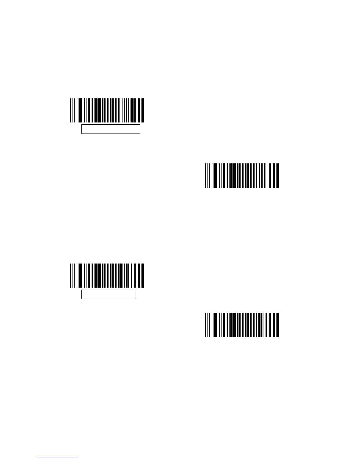
Enable/Disable UPC-A
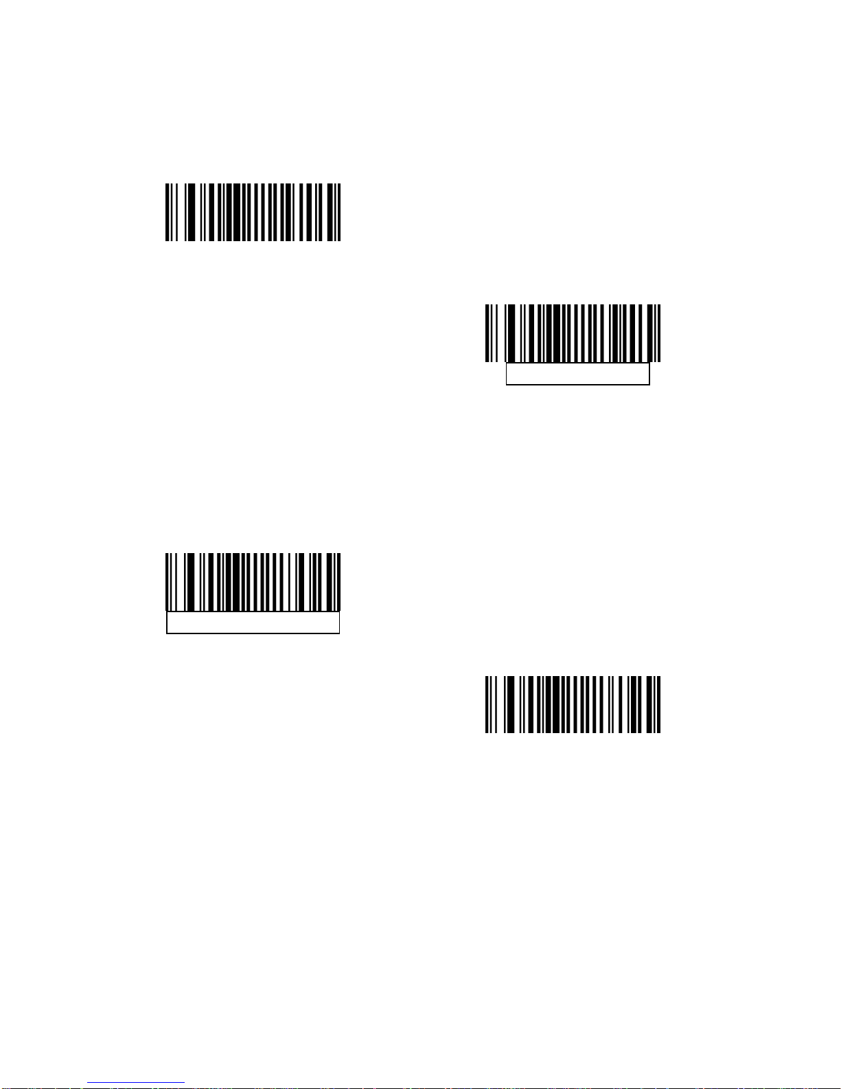
To enable or disable UPC-A, scan the appropriate barcode below.
Enable UPC-A
Disable UPC-A
Enable/Disable UPC-E
To enable or disable UPC-E, scan the appropriate bar code below.
Enable UPC-E
Disable UPC-E
Page 79
76
Enable/Disable UPC-E1
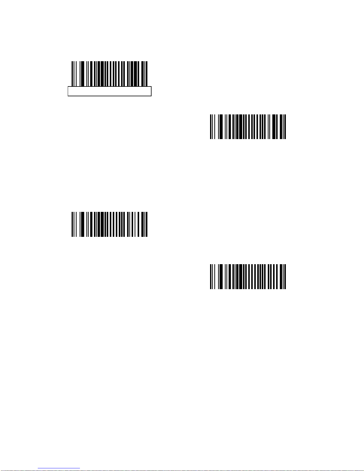
UPC-E1 is disabled by default. To enable or disable UPC-E1, scan the
appropriate bar code below.
Note: UPC-E1 is not a UCC (Uniform Code Council) approved symbology.
Enable UPC-E1
Disable UPC-E1
Enable/Disable EAN-8/JAN-8
To enable or disable EAN-8/JAN-8, scan the appropriate bar code below.
Enable EAN-8/JAN-8
Disable EAN-8/JAN-8
Page 80
77
Enable/Disable EAN-13/JAN-13
To enable or disable EAN-13/JAN-13, scan the appropriate bar code below.
Enable EAN-13/JAN-13
Disable EAN-13/JAN-13
Enable/Disable Bookland EAN
To enable/disable Bookland EAN, scan the appropriate barcode below.
Enable Bookland EAN
Disable Bookland EAN
Page 81

78
Decode UPC/EAN/JAN Supplementals
Supplemental are bar codes appended according to specific format
conventions (e.g., UPC A+2, UPC E+2, EAN 13+2). Six options are available.
If Decode UPC/EAN/JAN Only With Supplemental is selected,
UPC/EAN/JAN symbols without supplemental are not decoded.
If Ignore Supplemental is selected, and the decoder is presented
with a UPC/EAN/JAN with a supplemental, the UPC/EAN/JAN is
decoded and the supplemental bar code is ignored.
An Auto discriminate Option is also available. If this option is
selected, choose an appropriate UPC/EAN/JAN
Supplemental Redundancy value from the next page. A value of 5
or more is recommended.
Enable 378/379 Supplemental Mode to delay only EAN-13/JAN-13
bar codes starting with a ‘378’ or ‘379’ prefix by the supplemental
search process. All other UPC/EAN/JAN bar codes are exempt
from the search and are reported instantly upon deco des.
Select Enable 978 Supplemental Mode to delay only
EAN-13/JAN-13 bar codes starting with a ‘978’ prefix by the
supplemental search process. All other UPC/EAN/JAN bar codes
are exempt from the search and are reported instantly upon
decodes.
Select Enable Smart Supplemental Mode to delay only
EAN-13/JAN-13 bar codes starting with a ‘378’, ‘379’, or ‘978’ prefix
by the supplemental search process. All other UPC/EAN/JAN bar
codes are exempt from the search and are reported instantly upon
decodes.
Note: To minimize the risk of invalid data transmission, select either to decode
or ignore supplemental characters.
Page 82
79
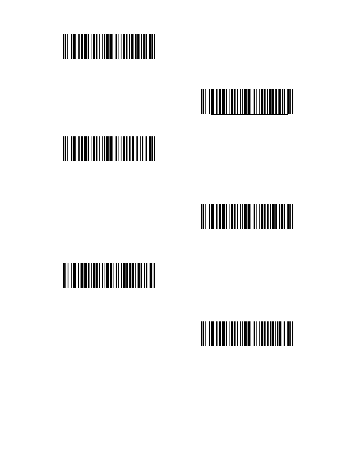
Decode UPC/EAN/JAN Only
With Supplemental
Ignore Supplemental
Auto discriminate UPC/EAN/JAN
Supplemental
Enable 378/379 Supplemental Mode
Enable 978 Supplemental Mode
Enable Smart Supplemental Mode
Page 83
80
UPC/EAN/JAN Supplemental Redundancy
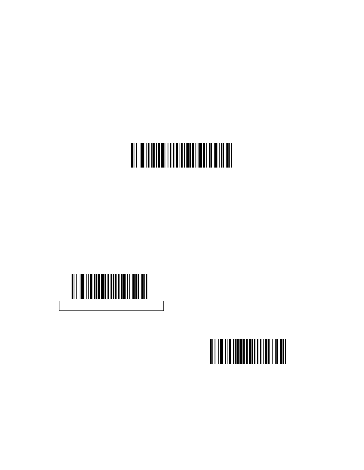
With Auto discriminate UPC/EAN/JAN Supplemental selected, this option
adjusts the number of times a symbol without supplemental is decoded before
transmission. The range is from two to thirty times. Five or above is
recommended when decoding a mix of UPC/EAN/JAN symbols with and
without supplemental, and the auto discriminate option is selected. The default
is set at 10.
Scan the bar code below to set a decode redundancy value. Next, scan two
numeric bar codes in Appendix D, Numeric Bar Codes. Single digit numbers
must have a leading zero. To correct an error or change a selection, scan
Cancel.
UPC/EAN/JAN Supplemental Redundancy
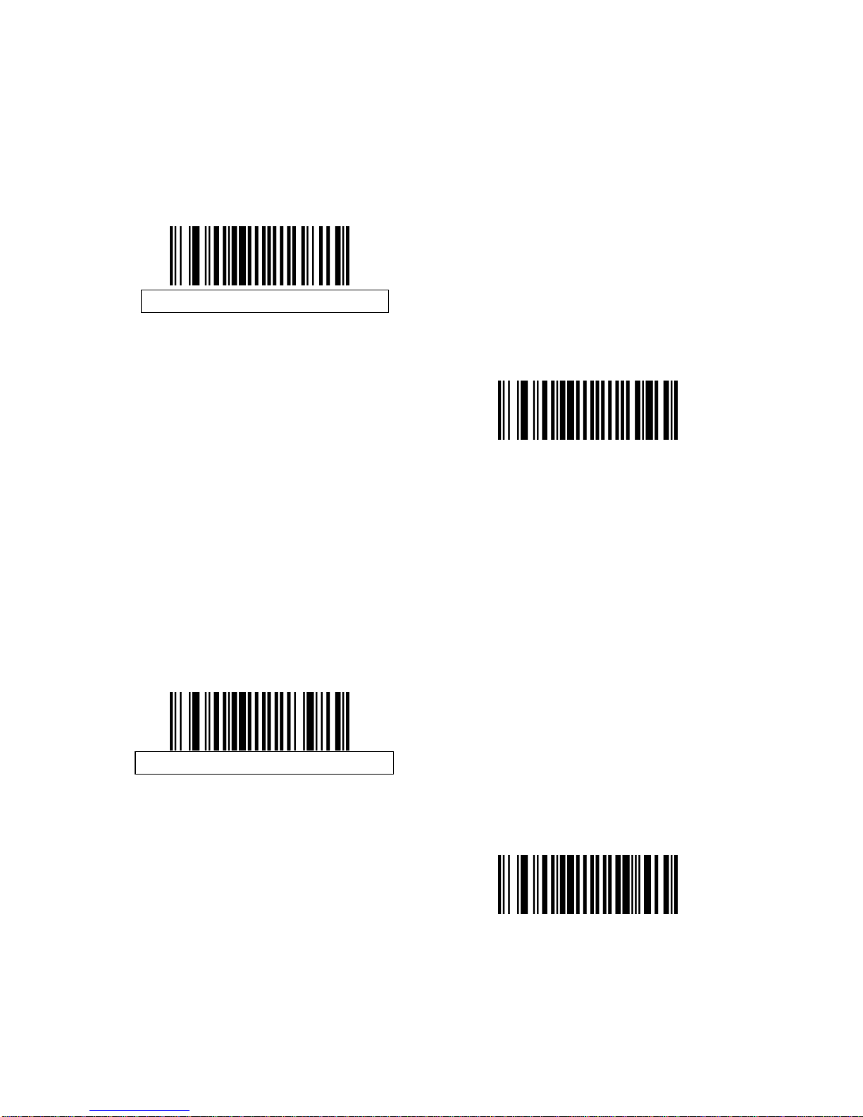
Transmit UPC-A Check Digit
The check digit is the last character of the symbol used to verify the integrity of
the data. Scan the appropriate bar code below to transmit the bar code data
with or without the UPC-A check digit. It is always verified to guarantee the
integrity of the data.
Transmit UPC-A Check Digit
Do Not Transmit UPC-A Check Digit
Page 84
81
Transmit UPC-E Check Digit
The check digit is the last character of the symbol used to verify the integrity of
the data. Scan the appropriate bar code below to transmit the bar code data
with or without the UPC-E check digit. It is always verified to guarantee the
integrity of the data.
Transmit UPC-E Check Digit
Do Not Transmit UPC-E Check Digit
Transmit UPC-E1 Check Digit
The check digit is the last character of the symbol used to verify the integrity of
the data. Scan the appropriate bar code below to transmit the bar code data
with or without the UPC-E1 check digit. It is always verified to guarantee the
integrity of the data.
Transmit UPC-E1 Check Digit
Do Not Transmit UPC-E1 Check
Digit
Page 85
82
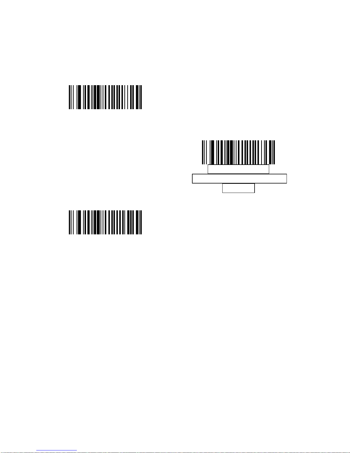
UPC-A Preamble
Preamble characters are part of the UPC symbol, and include Country Code
and System Character. There are three options for transmitting a UPC-A
preamble to the host device: transmit System Character only, transmit System
Character and Country Code (“0” for USA), and transmit no preamble. Select
the appropriate option to match the host system.
No Preamble (<DATA>)
System Character
(<SYSTEM CHARACTER>
<DATA>)
System Character & Country Code
(< COUNTRY CODE> <SYSTEM
CHARACTER> <DATA>)
Page 86
83
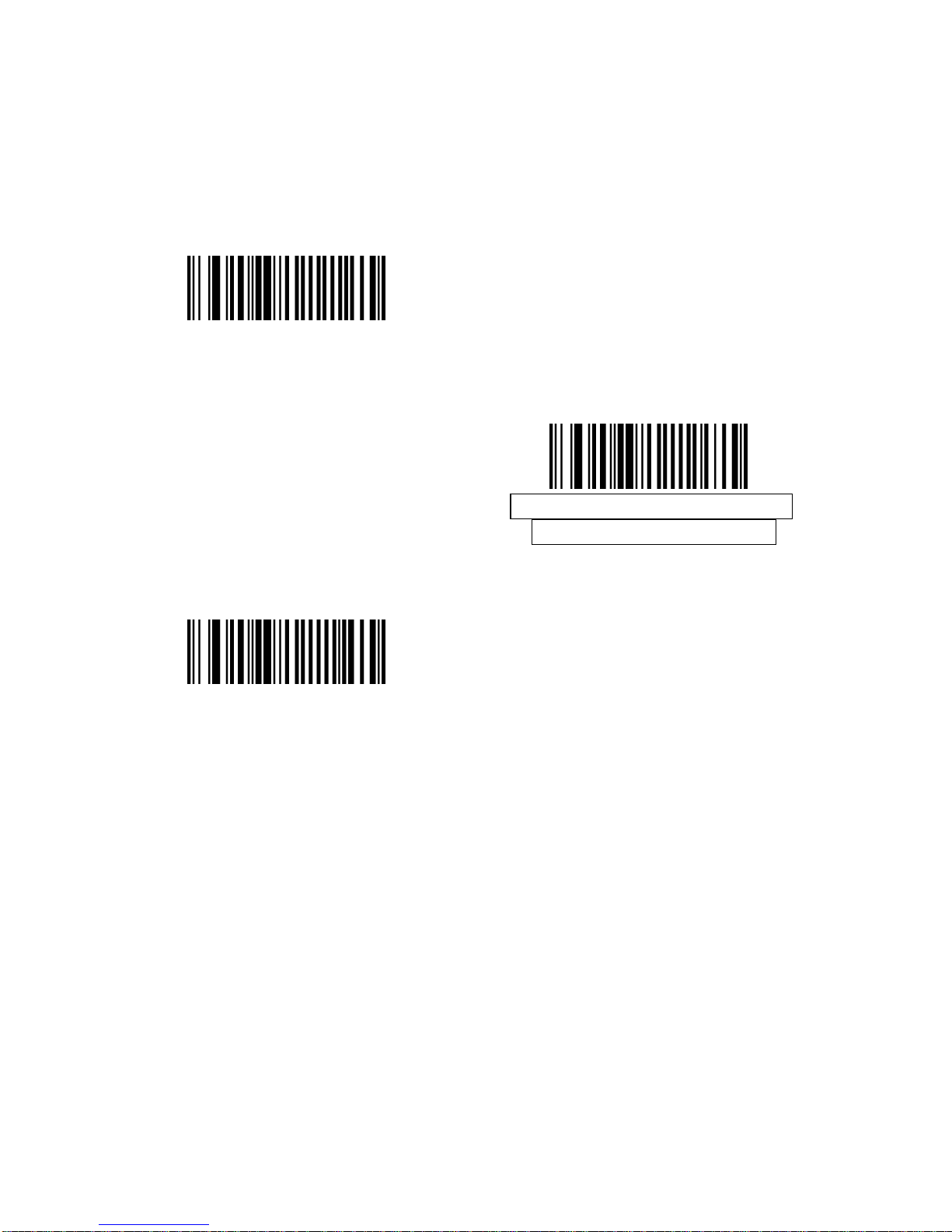
UPC-E Preamble
Preamble characters are part of the UPC symbol, and include Country Code
and System Character. There are three options for transmitting a UPC-E
preamble to the host device: transmit System Character only, transmit System
Character and Country Code (“0” for USA), and transmit no preamble. Select
the appropriate option to match the host system.
No Preamble (<DATA>)
System Character (<SYSTEM
CHARACTER> <DATA>)
System Character & Country Code(<
COUNTRY CODE> <SYSTEM
CHARACTER> <DATA>)
Page 87
84
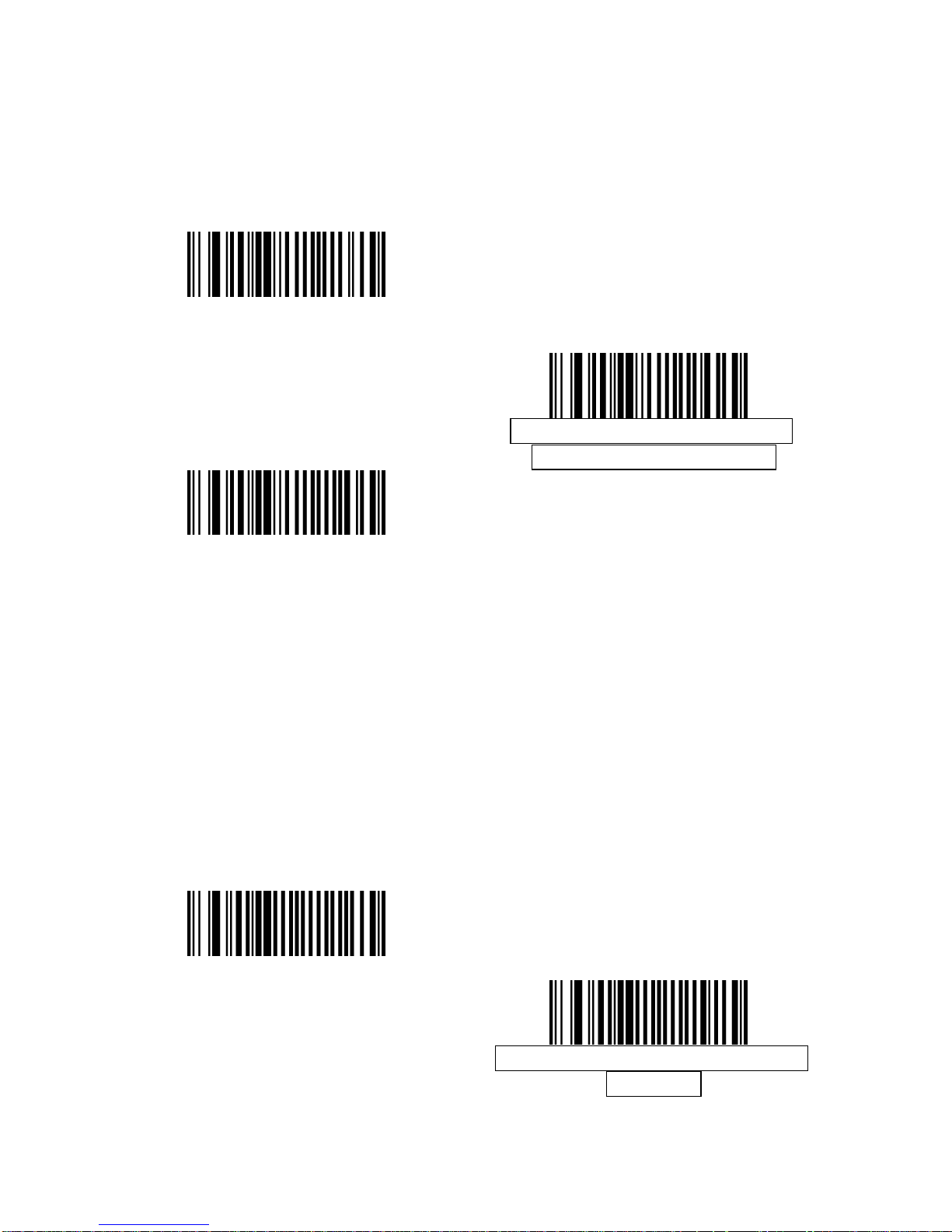
UPC-E1 Preamble
Preamble characters are part of the UPC symbol, and include Country Code
and System Character. There are three options for transmitting a UPC-E1
preamble to the host device: transmit System Character only, transmit System
Character and Country Code (“0” for USA), and transmit no preamble. Select
the appropriate option to match the host system.
No Preamble (<DATA>)
System Character (<SYSTEM
CHARACTER> <DATA>)
System Character & Country Code(<
COUNTRY CODE> <SYSTEM
CHARACTER> <DATA>)
Convert UPC-E to UPC-A
Enable this to convert UPC-E (zero suppressed) decoded data to UPC-A
format before transmission. After conversion, the data follows UPC-A format
and is affected by UPC-A programming selections (e.g., Preamble, Check
Digit). When disabled, UPC-E decoded data is transmitted as UPC-E data,
without conversion.
Convert UPC-E to UPC-A (Enable)
Do Not Convert UPC-E to UPC-A
(Disable)
Page 88
85
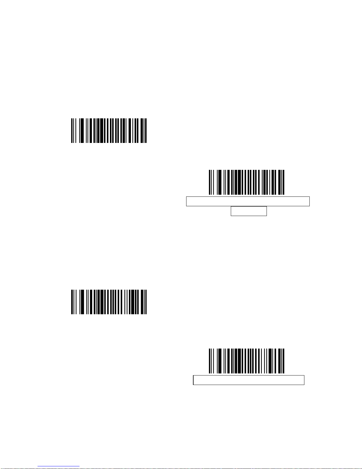
Convert UPC-E1 to UPC-A
Enable this to convert UPC-E1 decoded data to UPC-A format before
transmission. After conversion, the data follows UPC-A format and is affected
by UPC-A programming selections (e.g., Preamble, Check Digit).
When disabled, UPC-E1 decoded data is transmitted as UPC-E1 data, without
conversion.
Convert UPC-E1 to UPC-A (Enable)
Do Not Convert UPC-E1 to UPC-A
(Disable)
EAN-8/JAN-8 Extend
When enabled, this parameter adds five leading zeros to decoded EAN-8
symbols to make them compatible in format to EAN-13 symbols.
When disabled, EAN-8 symbols are transmitted as is.
Enable EAN/JAN Zero Extend
Disable EAN/JAN Zero Extend
Page 89

86
UCC Coupon Extended Code
When enabled, this parameter decodes UPC-A bar codes starting with digit ‘5’,
EAN-13 bar codes starting with digit ‘99’, and UPCA/EAN-128 Coupon Codes.
UPCA, EAN-13, and EAN-128 must be enabled to scan all types of Coupon
Codes.
Enable UCC Coupon Extended Code
Disable UCC Coupon Extended
Code
Note: Use the Decode UPC/EAN Supplemental Redundancy parameter to
control auto discrimination of the EAN128 (right half) of a coupon code.
Page 90
87
Code 128
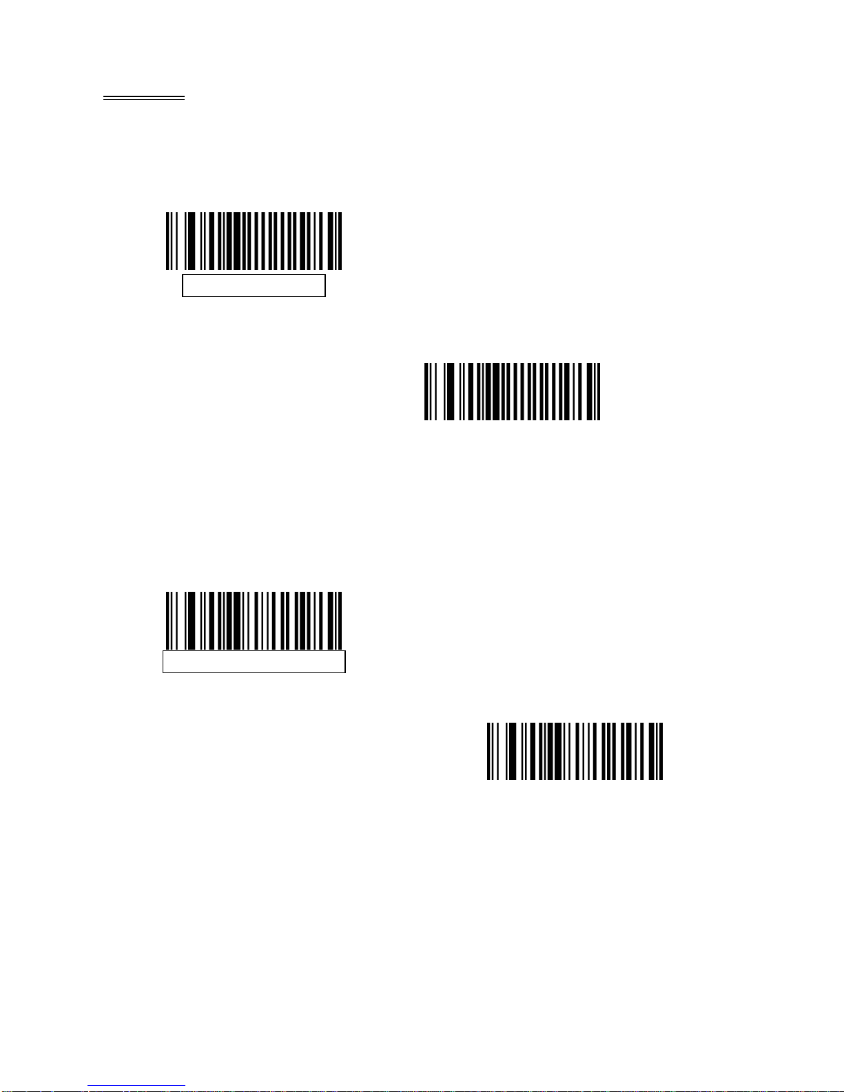
Enable/Disable Code 128
To enable or disable Code 128, scan the appropriate bar code below.
Enable Code 128
Disable Code 128
Enable/Disable UCC/EAN-128
To enable or disable UCC/EAN-128, scan the appropriate ba r code below.
Enable UCC/EAN-128
Disable UCC/EAN-128
Page 91
88
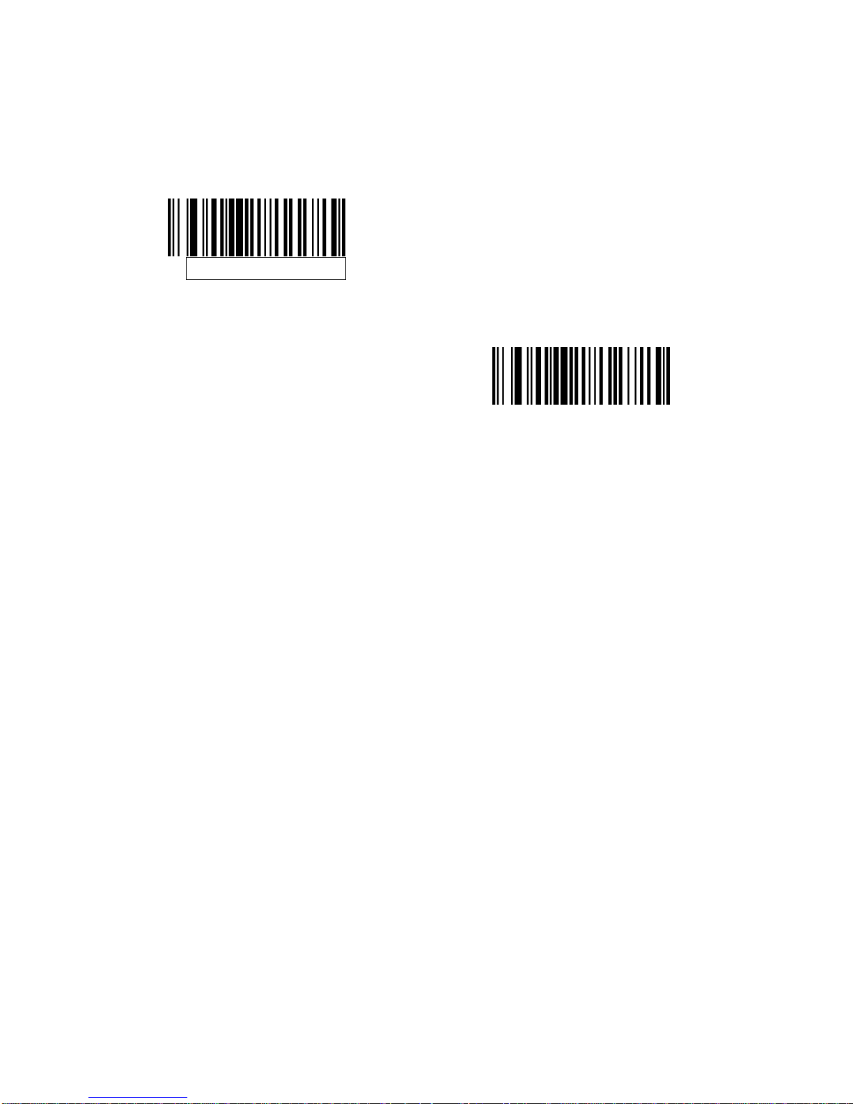
Enable/Disable ISBT 128
ISBT 128 is a variant of Code 128 used in the blood bank industry. Scan a bar
code below to enable or disable ISBT 128. If necessary, the host must perform
concatenation of the ISBT data.
Enable ISBT 128
Disable ISBT 128
Page 92
89
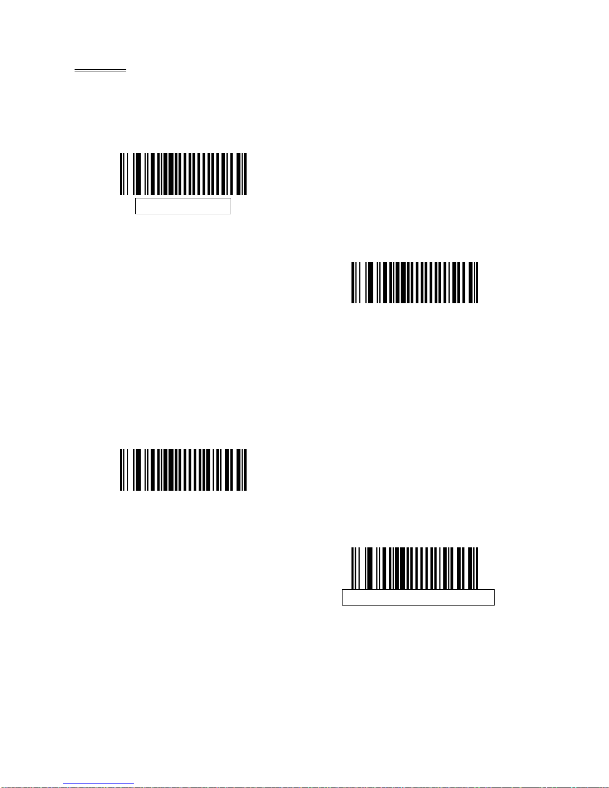
Code 39
Enable/Disable Code 39
To enable or disable Code 39, scan the appropriate bar code bel ow.
Enable Code 39
Disable Code 39
Enable/Disable Trioptic Code 39
Trioptic Code 39 is a variant of Code 39 used in the marking of computer tape
cartridges. Trioptic Code 39 symbols always contain six characters. To enable
or disable Trioptic Code 39, scan the appropriate bar code below.
Enable Trioptic Code 39
Disable Trioptic Code 39
Note: Trioptic Code 39 and Code 39 Full ASCII cannot be enabled
simultaneously.
Page 93
90
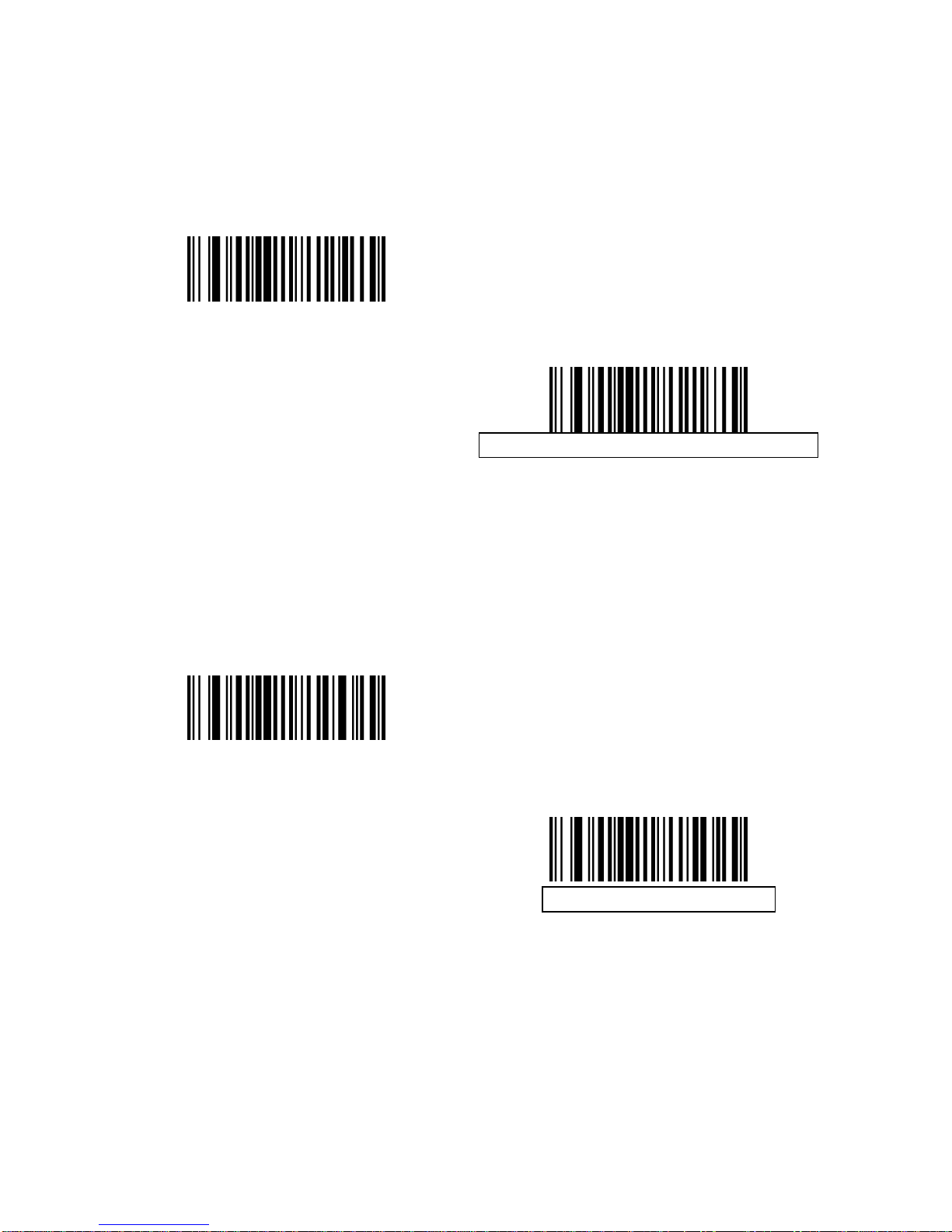
Convert Code 39 to Code 32
Code 32 is a variant of Code 39 used by the Italian pharmaceutical industry.
Scan the appropriate bar code below to enable or disable converting Code 39
to Code 32.
Note: Code 39 must be enabled for this parameter to function.
Enable Convert Code 39 to Code 32
Disable Convert Code 39 to Code 32
Code 32 Prefix
Scan the appropriate bar code below to enable or disable ad ding the prefix
character “A” to all Code 32 bar codes.
Note: Convert Code 39 to Code 32 must be enabled for this parameter to
function.
Enable Code 32 Prefix
Disable Code 32 Prefix
Page 94

91
Set Lengths for Code 39
The length of a code refers to the number of characters (i.e., human readable
characters), including check digit(s) the code contain s. Set lengths for Code 39
to any length, one or two discrete lengths, or lengths within a specific range. If
Code 39 Full ASCII is enabled, Length within a Range or Any Length is the
preferred options.
Note: When setting lengths for different bar code types by scanning single digit
numbers, single digit numbers must always be preceded by a leading zero.
One Discrete Length - Select this option to decode only Code 39
symbols containing a selected length. Select the length using the
numeric bar codes in Appendix D, Numeric Bar Codes. For
example, to decode only Code 39 symbols with 14 characters, scan
Code 39 - One Discrete Length, then scan 1 followed by 4. To
correct an error or change the selection, scan Cancel barcode.
Two Discrete Lengths - Select this option to decode only Code 39
symbols containing either of two selected lengths. Select lengths
using the numeric bar codes in Appendix D, Numeric Bar Codes.
For example, to decode only those Code 39 symbols containing
either 2 or 14 characters, select Code 39 - Two Discrete Lengths,
then scan 0, 2, 1, and then 4. To correct an error or change the
selection, scan Cancel barcode.
Length Within Range - Select this option to decode a Code 39
symbol with a specific length range. Select lengths using numeric
bar codes in Appendix D, Numeric Bar Codes. For example, to
decode Code 39 symbols containing between 4 and 12 characters,
first scan Code 39 - Length Within Range. Then scan 0, 4, 1, and 2
(single digit numbers must always be preceded by a leading zero).
To correct an error or change the selection, scan Cancel barcode.
Any Length - Select this option to decode Code 39 symbols
containing any number of characters within the decoder capability.
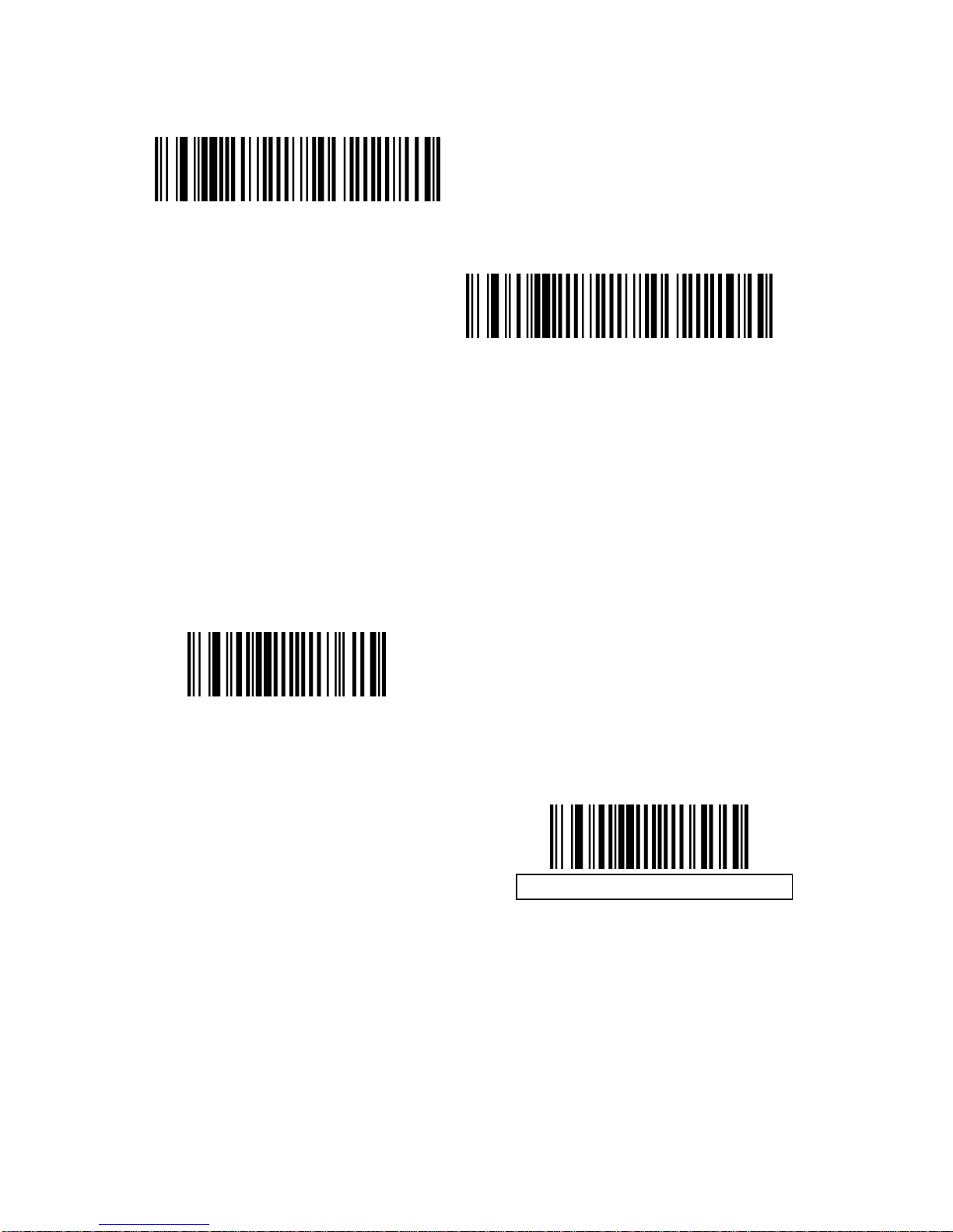
Code 39 - One Discrete Length
Code 39 - Two Discrete Lengths
Page 95
92
Code 39 - Length Within Range
Code 39 - Any Length
Code 39 Check Digit Verification
When this feature is enabled, the decoder checks the integrity of all Code 39
symbols to verify that the data complies with specified check digit algorithm.
Only Code 39 symbols which include a modulo 43 check digit are decoded.
Enable this feature if the Code 39 symbols contain a Modulo 43 check digit.
Enable Code 39 Check Digit
Disable Code 39 Check Digit
Page 96
93
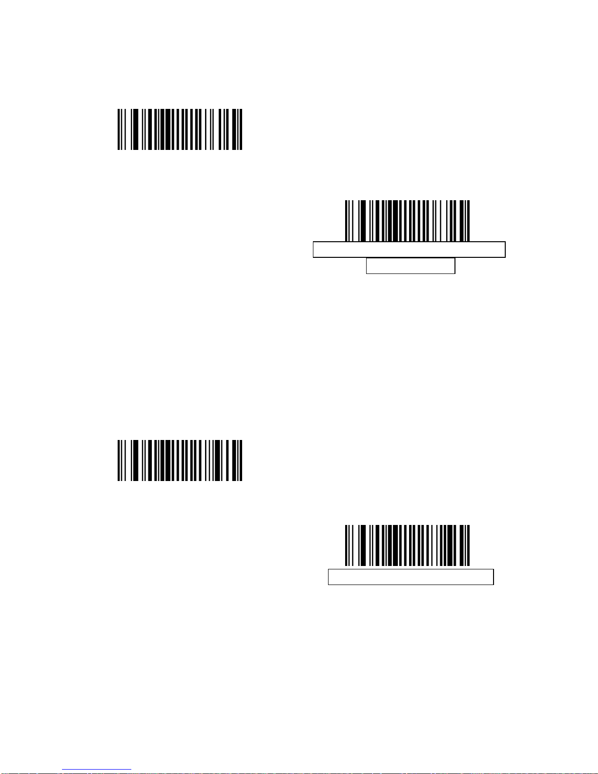
Transmit Code 39 Check Digit
Scan a bar code below to transmit Code 39 data with or without the check digit.
Transmit Code 39 Check Digit
(Enable)
Do Not Transmit Code 39 Check
Digit (Disable)
Note: Code 39 Check Digit Verification must be enabled for this parameter to
function.
Code 39 Full ASCII Conversion
Code 39 Full ASCII is a variant of Code 39 which pairs characters to encode
the full ASCII character set. To enable or disable Code 39 Full ASCII, scan the
appropriate bar code below.
Enable Code 39 Full ASCII
Disable Code 39 Full ASCII
Note: Trioptic Code 39 and Code 39 Full ASCII cannot be enabled
simultaneously.
Code 39 Full ASCII to Full ASCII Correlation is host-dependent, and is
therefore described in the ASCII Character Set Table for the appropriate
interface. See Appendix E, ASCII Character Set.
Page 97
94
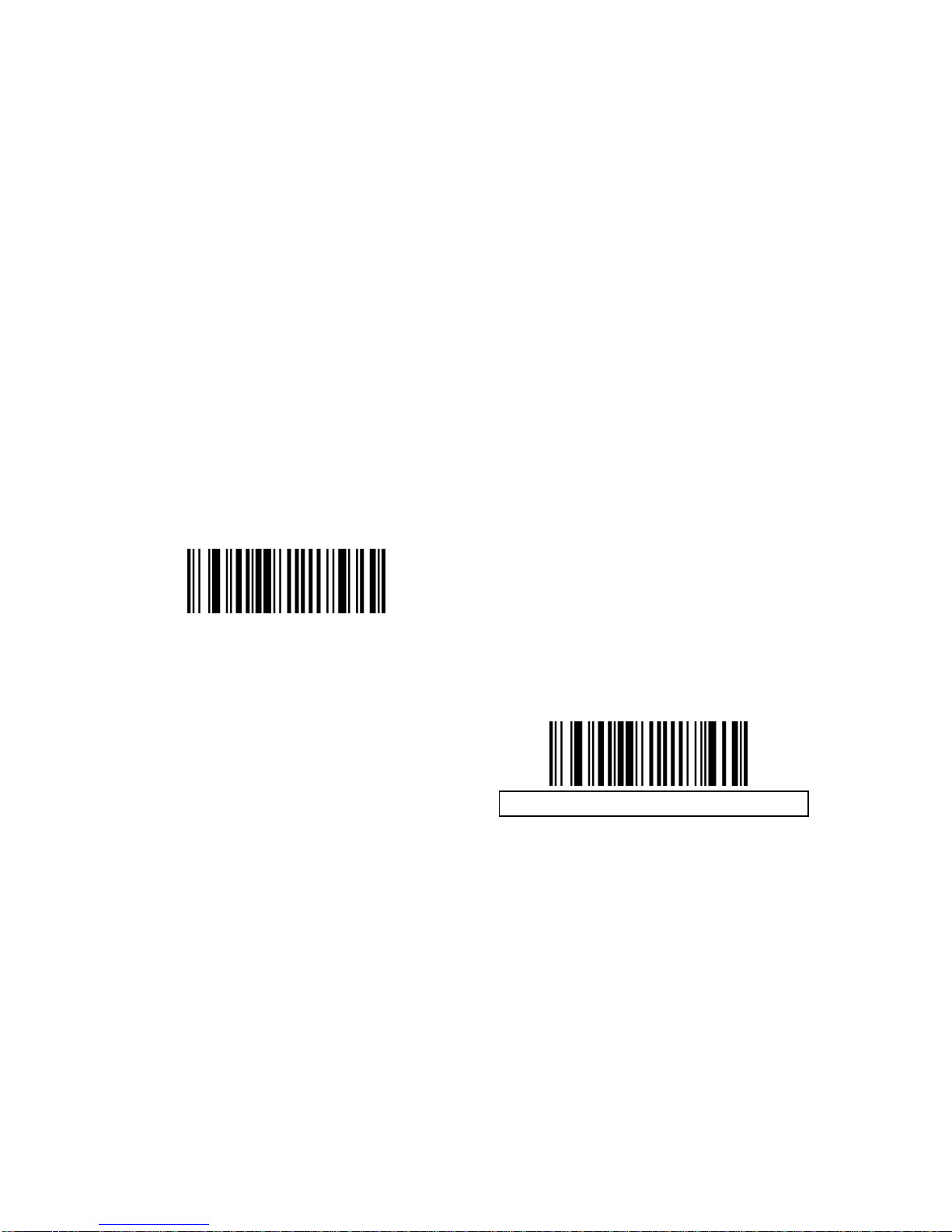
Code 39 Buffering (Scan & Store)
This feature allows the decoder to accumulate data from multiple Code 39
symbols.
Selecting the Scan and Store option (Buffer Code 39) temporarily buffers all
Code 39 symbols having a leading space as a first character for later
transmission. The leading space is not buffered.
Decode of a valid Code 39 symbol with no leading space causes transmi ssion
in sequence of all buffered data in a first-in first-out format, plus transmission
of the “triggering” symbol. See the following pages for further details.
When the Do Not Buffer Code 39 option is selected, all decoded Code 39
symbols are transmitted immediately without being stored in the buffer.
This feature affects Code 39 only. If selecting Buffer Code 39, we recommend
configuring the decoder to decode Code 39 symbology only.
Buffer Code 39 (Enable)
Do Not Buffer Code 39 (Disable)
While there is data in the transmission buffer, selecting Do Not Buffer Code
39 is not allowed. The buffer holds 200 bytes of information.
To disable Code 39 buffering when there is data in the transmission buffer, first
force the buffer transmission or clear the buffer.
Page 98

95
Buffer Data
To buffer data, Code 39 buffering must be enabled and a Code 39 symbol mu st
be read with a space immediately following the start pattern.
Unless the data overflows the transmission buffer, the decoder
issues a lo/hi beep to indicate successful decode and buffering.
(For overflow conditions, see Overfilling Transmission Buffer.)
The decoder adds the decoded data excludi ng the le ading sp ace to
the transmission buffer.
No transmission occurs.
Clear Transmission Buffer
To clear the transmission buffer, scan the Clear Buffer bar code below, which
contains only a start character, a dash (minus), and a stop character.
The decoder issues a short hi/lo/hi beep.
The decoder erases the transmission buffer.
No transmission occurs.
Clear Buffer
Note: The Clear Buffer contains only the dash (minus) character. In order to
scan this command, be sure Code 39 length is set to include length 1.
Transmit Buffer
There are two methods to transmit the Code 39 buffer.
1. Scan the Transmit Buffer bar code below. Only a start character, a
plus (+), and a stop character.
The decoder transmits and clears the buffer.
The decoder issues a Lo/Hi beep.
Transmit Buffer
2. Scan a Code 39 bar code with a leading character other than a
space.
The decoder appends new deco de data to buffered data.
The decoder transmits and clears the buffer.
The decoder signals that the buffer was transmitted with a lo/hi
beep.
The decoder transmits and clears the buffer.
Page 99

96
Note: The Transmit Buffer contains only a plus (+) character. In order to scan
this command, be sure Code 39 length is set to include length 1.
Overfilling Transmission Buffer
The Code 39 buffer holds 200 characters. If the symbol just read results in an
overflow of the transmission buffer:
The decoder indicates that the symbol was rejected by issuing
three long, high beeps.
No transmission occurs. The data in the buffer is not affected.
Attempt to Transmit an Empty Buffer
If the symbol just read was the Transmit Buffer symbol and the Code 39 buffer
is empty:
A short lo/hi/lo beep signals that the buffer is empty.
No transmission occurs.
The buffer remains empty.
Page 100

97
Code 93
Enable/Disable Code 93
To enable or disable Code 93, scan the appropriate bar code bel ow.
Enable Code 93
Disable Code 93
Set Lengths for Code 93
The length of a code refers to the number of characters (i.e., human readable
characters), including check digit(s) the code contain s. Set lengths for Code 93
to any length, one or two discrete lengths, or lengths within a specific range.
One Discrete Length - Select this option to decode only Code 93
symbols containing a selected length. Select the length using the
numeric bar codes in Appendix D, Numeric Bar Codes. For
example, to decode only Code 93 symbols with 14 characters, scan
Code 93 - One Discrete Length, then scan 1 followed by 4. To
correct an error or to change the selection, scan Cancel barcode.
Two Discrete Lengths - Select this option to decode only Code 93
symbols containing either of two selected lengths. Select lengths
using the numeric bar codes in Appendix D, Numeric Bar Codes.
For example, to decode only those Code 93 symbols containing
either 2 or 14 characters, select Code 93 - Two Discrete Lengths,
then scan 0, 2, 1, and then 4. To correct an error or to change the
selection, scan Cancel barcode.
Length Within Range - Select this option to decode a Code 93
symbol with a specific length range. Select lengths using the
numeric bar codes in Appendix D, Numeric Bar Codes. For
example, to decode Code 93 symbols containing betwee n 4 and 1 2
 Loading...