

Page 1

Cover
Model: DBW1C
1
Page 2

Page 3

Revision History
Changes to the original manual are listed below:
Version Date Description of Version
1.0 September 1, 2014 Preliminary release
USER’S MANUAL
Di Bar Watch
i
Page 4

USER’S MANUAL
Important Notice
No warranty of any kind is made in regard to this material, including, but not limited to,
implied warranties of merchantability or fitness for any particular purpose. We are not
liable for any errors contained herein nor for incidental or consequential damages in
connection with furnishing, performance or use of this material. We shall be under no
liability in respect of any defect arising from fair wear and tear, willful damage,
negligence, abnormal working conditions, failure to follow the instructions and warnings,
or misuse or alteration or repair of the products without written approval. No part of this
document may be reproduced, transmitted, stored in a retrieval system, transcribed, or
translated into any human or computer or other language in any form or by any means
electronic, mechanical, magnetic, optical, chemical, biological, manual or otherwise,
except for brief passages which may be quoted for purposes of scholastic or literary
review, without express written consent and authorization. We reserve the right to make
changes in product design without reservation and without notification. The material in
this guide is for information only and is subject to change without notice. All trademarks
mentioned herein, registered or otherwise, are the properties of their various, ill,
assorted owners.
General Handling Precautions
Do not dispose the scanner in fire.
Do not put the scanner directly in the sun or by any heat source.
Do not use or store the scanner in a very humid place.
Do not drop the scanner or allow it to collide violently with other objects.
Do not take the scanner apart without authorization
Guidance for Printing
This manual is in A5 size. Please double check your printer setting before printing it out.
When the barcodes are to be printed out for programming, the use of a high-resolution
laser printer is strongly suggested for the best scan result.
Copyright © 2014. All rights reserved.
ii
Di Bar Watch
Page 5

USER’S MANUAL
Radio Notice
This equipment generates uses and can radiate radio frequency energy. If not installed
and used in accordance with the instructions in this manual, it may cause interference to
radio communications.
Radio and Television Interference
Operation of this equipment in a residential area can cause interference to radio or
television reception. This can be determined by turning the equipment off and on. The
user is encouraged to try to correct the interference by one or more of the following
measures:
- Reorient the receiving antenna.
- Relocate the device with respect to the receiver.
- Move the device away from the receiver.
- Plug the device into a different outlet so that the device and the receiver are on
different branch circuits.
If necessary the user may consult the manufacturer, and authorized dealer, or
experienced radio/television technician for additional suggestions. The user may find
the following booklet prepared by the Federal Communications Commission helpful:
“How to Identify and Resolve Radio-TV Interference Problems.” This booklet is available
from the U.S. Government Printing Office, Washington, DC 20402 U.S.A., Stock No.
004000003454.
Laser Safety
This equipment generates, uses, and can radiate radio frequency energy. If not installed
and used in accordance with the instructions in this manual, it may cause interference to
radio communications.
Di Bar
Watch
iii
Page 6

USER’S MANUAL
Laser Light Viewing: The scan window is the only aperture through which laser light may
be observed from this product. A failure of the scanner engine, while the laser diode
continues to emit a laser beam, may cause emission levels to exceed those for safe
operation. The scanner has safeguards to prevent this occurrence. If, however, a
stationary laser beam is emitted, the failing scanner should be disconnected from its
power source immediately.
Adjustments: Do not attempt any adjustments or alteration of this product. Do not
remove the protective housing of the scanner. There are no user-serviceable parts inside.
Optical: The use of optical instruments with this product will increase the eye hazard.
Optical instruments include binoculars, magnifying glasses, and microscopes but do not
include normal eye glasses worn by the user.
CAUTION: Use of controls or adjustments or performance of procedures other than those
specified herein may result in hazardous radiation exposure.
Power Supply
Use only the type of battery and the charging equipments that came with your
scanner.
Using any other type of battery and charging equipment may damage the scanner
and invalidate the warranty.
Do not short the battery terminals. The battery could overheat.
Do not attempt to split or peel the outer casing.
Remove the battery if the scanner is not going to be used for a long time. If the
battery is left unused for more than 3 months, you need to charge the battery
before use.
Caution
RISK OF EXPLOSION IF BATTERY IS REPLACED BY AN INCORRECT TYPE
DISPOSE OF USED BATTERIES ACCORDING TO THE INSTRUCTIONS
iv
Di Bar Watch
Page 7

USER’S MANUAL
Tips to help improve your wireless network
1. Position the access point (host/dongle) in a relatively empty space at central location.
When possible, place the access point in a central location on the high ground (1m or above). If your access
point is against an outside wall, the signal will be weak on the other side of the room.
2. Move the access point (host/dongle) off the floor and away from walls and metal objects (such as metal file
cabinets). Metal objects, walls, and floors will interfere with your wireless signals. The closer your access
point is to these obstructions, the more severe the interference, and the weaker your connection will be.
Di Bar Watch
v
Page 8
USER’S MANUAL
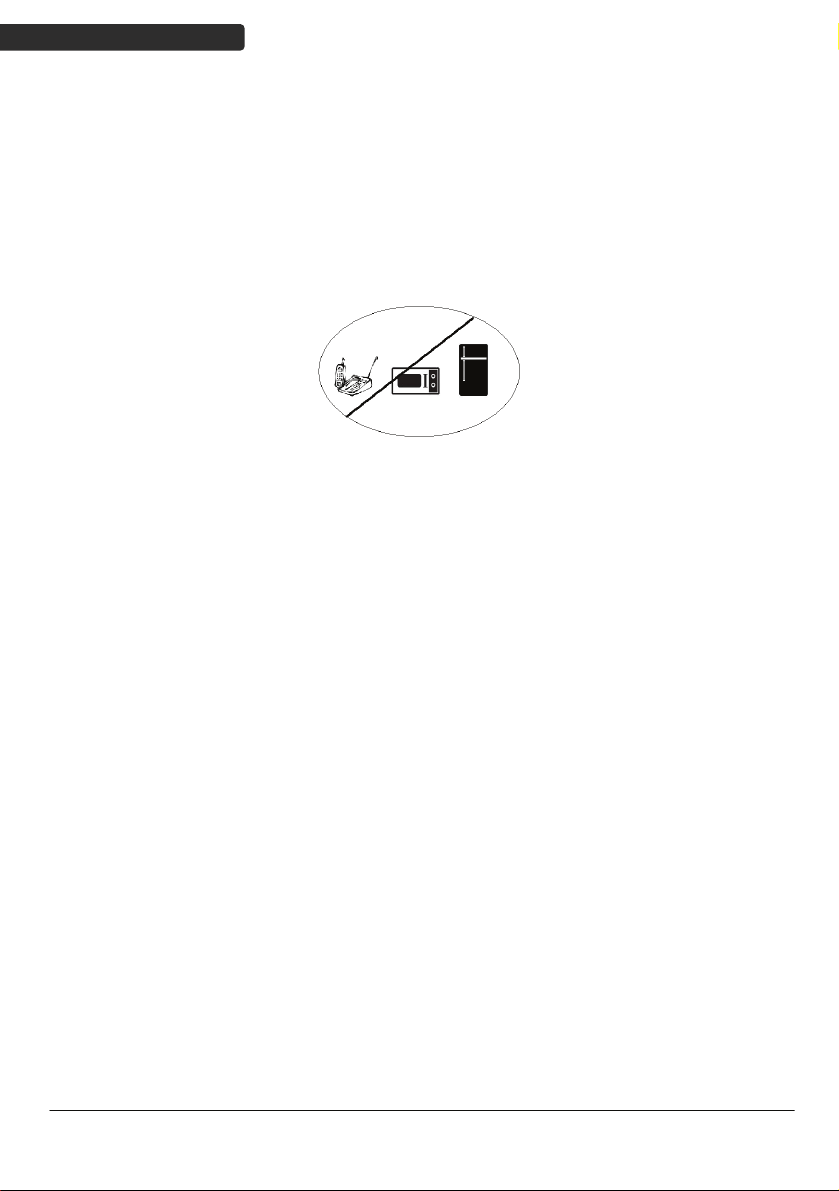
3. Reduce wireless interference.
The most common wireless technology, 802.11g (wireless-G), operates at a frequency of 2.4 gigahertz (GHz).
Many cordless phones, microwave ovens, hospital equipments, refrigerator, LED, and other wireless
electronics also use this frequency. If you use these wireless devices in your office, your device might not be
able to "hear" the signals over the noise coming from them.
If your network uses wireless-G, you can quiet the noise by avoiding wireless electronics that use the 2.4
GHz frequency. Instead, look for cordless phones and other devices that use the 5.8 GHz or 900 megahertz
(MHz) frequencies. Because 802.11n (wireless-N) operates at both 2.4 GHz and the less frequently used 5.0
GHz frequency, you may experience less interference on your network if you use this technology.
Avoid possible wireless interference
4. Update the firmware or driver of your wireless dongle.
If you are using a wireless dongle or other similar devices to make the connection, getting the latest
firmware or driver updates may improve the performance. Visit your manufacturer’s website for the
updates.
vi
Di Bar Watch
Page 9

USER’S MANUAL
Table of Contents
Important Notice..................................................................................................................ii
General Handling Precautions..............................................................................ii
Guidance for Printing ...........................................................................................ii
Laser Safety......................................................................................................... iii
Power Supply ......................................................................................................iv
Caution................................................................................................................iv
Visible Indicators..........................................................................................................1
Definition for LED function...................................................................................1
Definition for Key function...................................................................................1
ACK/NAK Protocol or Frame Packing............................................................................2
Scanner to Remote Application....................................................................................3
Firmware Update .........................................................................................................4
Programming Guide.............................................................................................................5
Connecting to a Host....................................................................................................9
USB Online Mode.................................................................................................9
Dongle Host Mode .............................................................................................10
Wireless Mode ...................................................................................................11
Connect to PC [Window]....................................................................................12
Secure Simple Pairing.........................................................................................23
Data Transmit Method .......................................................................................24
System Function Settings ...........................................................................................27
Scan Mode .........................................................................................................28
Radio Communication Setting............................................................................29
Operation Function Setting ................................................................................37
Interface Settings ...............................................................................................40
The Symbologies ................................................................................................44
Data Editing........................................................................................................67
Appendix 1: USB Virtual COM Driver Installation ..............................................75
Appendix 2: Barcode Length Setting..................................................................76
Di Bar Watch
vii
Page 10

Page 11

Visible Indicators
Definition for LED function
USER’S MANUAL
LED1
BLUE/ORANGE
LED2
RED/GREEN
BT Connected Stable Blue
BT Try to or Wait for connect Slow blink Blue
BT Transmitting data Fast Blink Blue
BT Disconnected Turn OFF Blue (w/ indication Beep)
Working in Memory Mode Slow blink Orange
Memory nearly FULL(80% FULL) Fast blink Orange
Memory FULL Stable Orange(w/Caution Beep)
Power ON Stable RED
Good Read Blink once Green w/Beep
Battery Low (<30%) Slow Blink Red
Battery Very Low (<15%) Fast Blink Red
Battery Very Low (<5%) Fast Blink Red(w/ Caution Beep)
Definition for Key function
Tri gger Key
F1
F2 Press long period : Send memory data when working in
Combination keys Trigger +F1(Press long period) : Delete last record in memory
1. Press long period : Power ON
2. Press/Click : Trigger to read barcode when working
1. Click : Software keyboard ON/OFF for iOS/Android
2. Press long period : Toggle Memory mode ON/OFF
memory mode
mode
Trigger +F2(Press long period) : Delete all recodes in memory
mode
F1+F2(Press long period) : Disconnect BT pairing
F1+F2+Trigger (Press long period) : Power Off
(*)Press long period = 4 sec
Di Bar Watch
1
Page 12
USER’S MANUAL
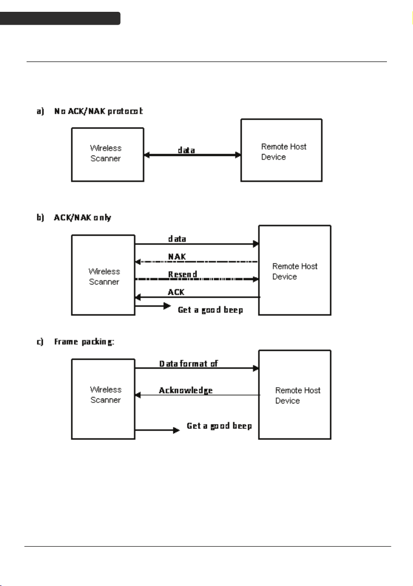
ACK/NAK Protocol or Frame Packing
When scanner is in SPP Master/Slave mode, and add in the data protocol or packing
could confirm the data reliability. Refer to below for different setting options:
2
Di Bar Watch
Page 13
USER’S MANUAL
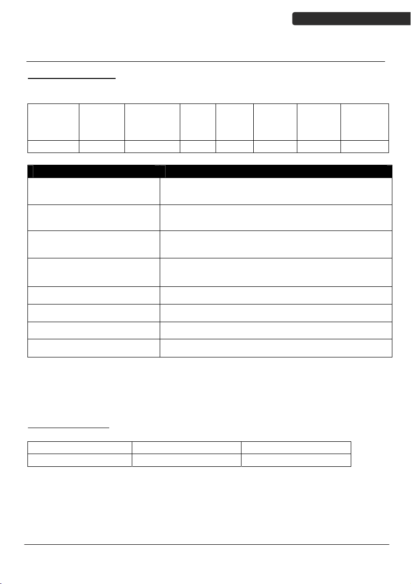
Scanner to Remote Application
Data Format of Packet
To send a data (barcode) to the remote application, the scanner has to encapsulate it:
EAH
(Header)
1 byte 1 byte 1 byte 1 byte Varies 1 byte 1 byte 1 byte
Header Character (EAH) The character ID at the head of every data. It has to
Size of Payload The encapsulated data length excluding header
Format Byte (FEH) Differentiate data format; barcode data is always FEH.
Data ID The number of each data. If receive the same ID more
Barcode Type (1 byte) Please refer to the Barcode Type Table.
Size of
payload
Title Definition
FEH
(Format
Byte)
Data
ID
start with EAH.
character.
than once, only the first one is valid, delete the rest.
Data
Barcode
Type
AEH
(End of
Byte)
Reserved
Byte
Data Decoded barcode data.
End of Byte (AEH) Record data ends.
Reserved Byte Reserved for future use.
Example:
If Code39 barcode data is "ABCD", than sender sends out:
EAH + 0AH + FEH + ID + "ABCD "+ 11H+AEH + Reserved Byte
0AH = 1+1+1+4+1+1+1
Acknowledge packet
55H (Header ) Data ID 55H (end of byte)
1 byte 1 byte 1 byte
Example:
If scanner sends out:
EAH , 0AH , FEH , 01H , "ABCD ", 011H, AEH , EEH
Remote acknowledges: 55H +01H + 55H
Di Bar Watch
3
Page 14

USER’S MANUAL
Barcode Type Table
Code Value
Code39 0x11
Codabar 0x01
Code128 0x03
Interleaved 2/5 0x02
Code93 0x06
UPC-E 0x14
UPC-A 0x24
EAN-8 0x34
EAN-13 0x44
Chinese Post Code 0x05
MSI 0x07
Firmware Update
To update the firmware, scan the Start of Configuration barcode then scan Dongle USB
Update or Scanner USB Update to enter Firmware Update mode. To exit Firmware
Update mode without updating, please remove and re-insert the battery.
Dongle USB Update
Scanner USB Update
4
Start Of Configuration
Update firmware using dongle
(Dongle Host mode only)
Update firmware using USB connection
Di Bar Watch
Page 15
USER’S MANUAL
Programming Guide
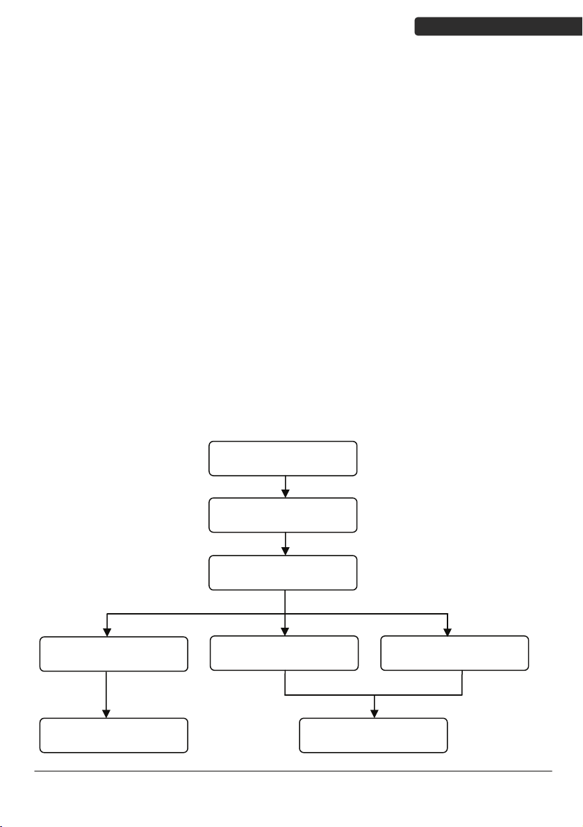
Program Procedure Using Barcode Manual
1. Power up the scanner.
2. Scan the Start of Configuration barcode.
3. Scan the barcode for the desired feature. Multiple features can be
enabled/disabled before scanning the End of Configuration barcode.
4. Scan the End of Configuration barcode and save the new configuration. Power
off and on the scanner when the setting is done.
5. To give up a configuration change, power off the scanner before scanning the
End of Configuration barcode or scan the Abort barcode.
6. For some parameter setting, such as barcode length and identifier code, it is
required to scan the Set barcode to save the configuration.
Configuration” barcode
Finish the configuration
Di Bar Watch
Power up the scanner
Scan the “Start of
Configuration” barcode
an barcode of the
Sc
desired feature
Discard the configuration
Power off the scannerScan the “Abort”barcode Scan the “End of
5
Page 16

USER’S MANUAL
Default Parameters
The factory default setting table gives the default settings of all the programmable
parameters. The default settings will be restored whenever the "Reset" programming
label is scanned and the scanner is in programming mode. Default values are highlighted
in grey background in the settings.
Factory Default Setting
Radio communication
Wireless host Dongle
Pairing mode Unlocked
Data transmit Normal
Radio protocol timeout 5 seconds
Power off timeout 20 minutes
Encryption Enable
Dongle Host
RS-232 communication
Terminator <CR><LF>
USB Communication
Terminator Enter
Code mode Scan code
Keyboard US keyboard
Pair contact on dongle Enable
Scanner
Decoder Selection Default
EAN/UPC Enable
CODE 39 Enable
Code 32 Disable
CODABAR Enable
ITF 2 OF 5 Enable
MSI Disable
Chinese post code Disable
Code 93 Enable
Code 128 Enable
EAN-128 Disable
Telepen Disable
Code 11 Disable
Parameter Default
6
Di Bar Watch
Page 17

USER’S MANUAL
Standard 2 of 5 Disable
Industrial 2 of 5 Disable
GS1 DataBar Disable
Beeper Sound Default
Frequency Medium
Duration Medium
Operating Parameter Default
Scan mode Trigger mode
Stand mode Enable
Header and trailer None
Inter-message delay None
Inter-character delay None
Code Identifiers Default
Identifier code as ZEBEX
Disable
standard
Identifier code as AIM
Disable
standard
Code 39 identifier code M
ITF 2 of 5 identifier code I
Chinese post code identifier
H
code
UPC-A identifier code A
UPC-E identifier code E
EAN-13 identifier code F
EAN-8 identifier code FF
Codabar identifier code N
Code 128 identifier code K
Code 93 identifier code L
MSI identifier code P
Code 11 identifier code O
Standard 2 of 5 identifier code S
Industrial 2 of 5 identifier
D
code
GS1 DataBar identifier code RS
GS1 DataBar Limited identifier
RL
code
GS1 DataBar Expanded
RX
identifier code
Di Bar Watch
7
Page 18

USER’S MANUAL
Default Data Transmit Format
Code Message format
EAN-13 D1 D2 D3 D4 D5 D6 D7 D8 D9 D10 D11 D12 D13
EAN-8 D1 D2 D3 D4 D5 D6 D7 D8
UPCA D1 D2 D3 D4 D5 D6 D7 D8 D9 D10 D11 D12
UPCE D1 D2 D3 D4 D5 D6 D7 D8
CODE128 D1-Dx (default 3~62)
EAN128 C1 D1-Dx (default 3~62)
CODE39 D1-Dx (default 3~62)
CODABAR D1-Dx (default 6~32)
INTERLEAVED 2/5 D1-Dx (default 6~32)
CHINESE POST CODE D1-Dx (default 8~32)
CODE93 D1-Dx (default 3~32)
MSI D1-Dx (default 6~32)
8
Di Bar Watch
Page 19

USER’S MANUAL
Connecting to a Host
The scanner provides several data transmit methods to communicate with the host. User
may select the method according to their preferences. Read this section to learn the
setups for connecting to different hosts.
USB Online Mode
The scanner connects directly to a USB host to recharge and transmit data. You may
enable or disable the functions using the following settings.
Disable USB communication
USB online scan disable
Enable USB communication
USB online scan enable
Set USB as the primary connection
USB online scan, Ignore
radio communication
Start Of Configuration
Disable USB communication.
Wireless connection as the primary communication
option to the host. USB connection is only used when
wireless is disconnected.
USB connection as the primary communication option
to the host when it is available. Wireless mode is set
as the secondary option.
Di Bar Watch
End Of Configuration
9
Page 20

USER’S MANUAL
Start Of Configuration
Dongle Host Mode
The scanner communicates with the host through the dongle. Typically, scanner and
dongle in the same delivery box are paired and corresponded to host interface in factory.
To check if the scanner is paired to the dongle, check the scanner LED for slow blue flash
and check the top dongle LED for steady blue light. If scanner LED and dongle LED are
both flashing blue, follow the steps below to radio connect the scanner and dongle.
Dongle Host Pairing
1. Please make sure the scanner LED is flashing blue indicating it’s not linked to
any host. If the LED shows steady blue, the scanner is already paired to
another scanner so you must unpair the scanner before continuing.
2. Power on the scanner and enable dongle host mode if necessary.
3. Use the scanner to scan the pairing barcode at the bottom of the dongle to
begin pairing. 3 short beeps will be heard.
4. The LED indicator on the scanner will flash blue rapidly indicating search
mode in process. The LED on the dongle becomes steady blue when the
pairing is successful.
5. Scan the corresponding host interface the dongle is using to begin using the
scanner.
Dongle Host mode enable
Return to USB default
Return to Virtual COM
Port default
Enable dongle mode with this setting
Return to dongle USB communication.
(Communication dongle link required)
Return to Virtual COM Port setting
10
End Of Configuration
Di Bar Watch
Page 21

USER’S MANUAL
Start Of Configuration
Wireless Mode
The scanner connects to the host via wireless connection. You may select SPP Master or
SPP Slave for PC connection or select HID mode and Smart phone mode for smart phone
connection.
SPP Slave Mode
In this mode, the scanner connects to the host /PC via wireless connection and performs
like there’s a serial connection. In SPP Slave mode, the scanner is discoverable from a
remote device and it can request the scanner for connection. There are several ways to
connect the wireless scanner to your PC. If you have your own applications please check
their User’s Manuals for pairing instructions.
To connect a wireless device to Window based system for the first time:
1. Turn on the host computer and activate its wireless connection.
2. Select “Add Bluetooth device”. Or open the dialog Bluetooth devices and click
“Add ”.
3. Power on the scanner and program it with “SPP Slave mode” label.
Enable wireless SPP Slave mode.
Scanner SPP Slave enable
4. On Devices tab, click Add. This will open the Add Bluetooth Device Wizard.
5. Select the "My device is set up and ready to be found" checkbox, and then
click Next.
6. The scanner should be on the list of discoverable devices. The default name
of the scanner is “DiBar” with address. Select the device and click “Next”.
7. Select “Let me choose my own passkey” and enter the pin code. The default
pin code is “12345678.
8. Click “Next” to connect the scanner to the host. A short beep should be
heard upon connection.
Di Bar Watch
End Of Configuration
11
Page 22
USER’S MANUAL
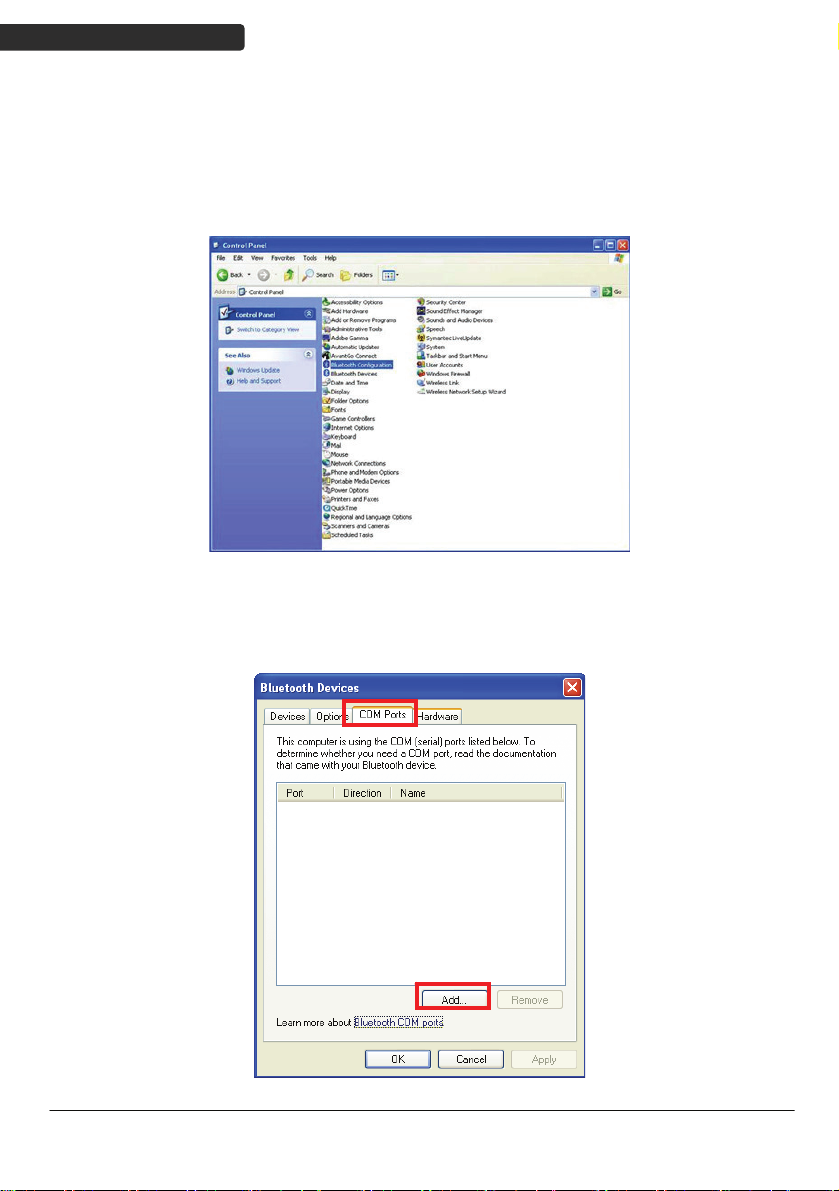
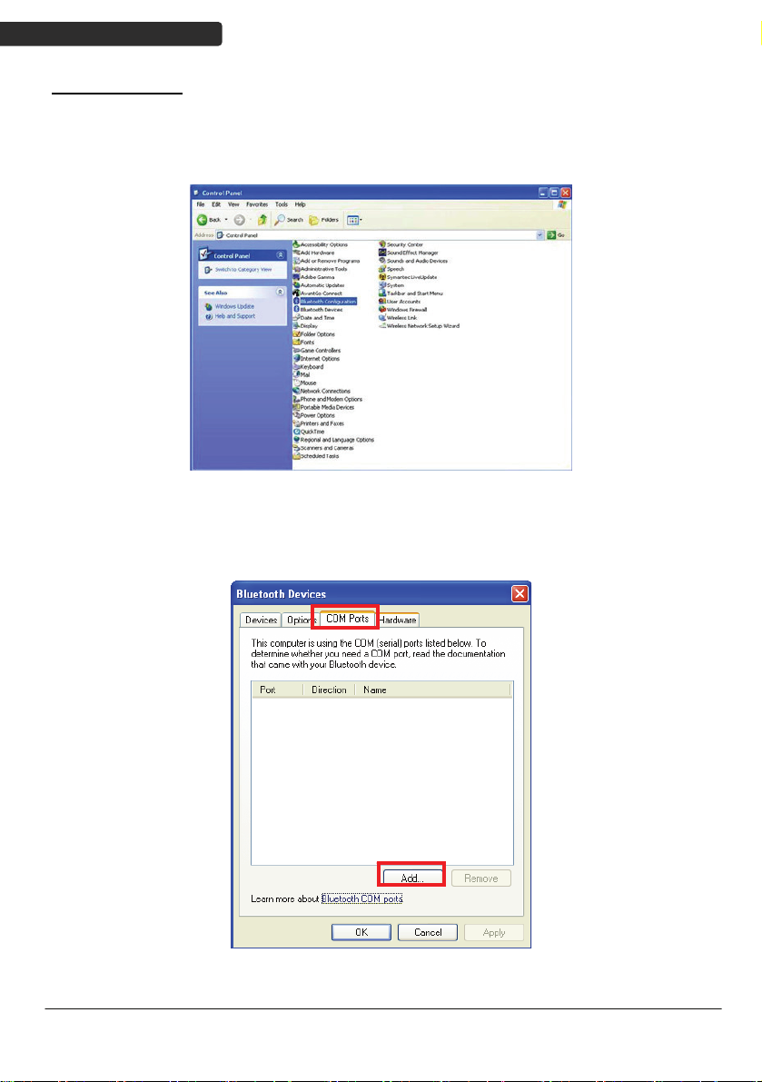
Connect to PC [Window]
To connect a wireless device to Window XP for the first time:
1. Turn on the host computer and activate its wireless connection.
2. Select “Add wireless device”. Or open the dialog BT devices and click “Add”.
3. Power on the scanner and program it with “Scanner SPP Slave enable” label
from the previous page.
4. In COM Ports page, click “Add”. This will open the Add COM port window.
12
Di Bar Watch
Page 23
USER’S MANUAL
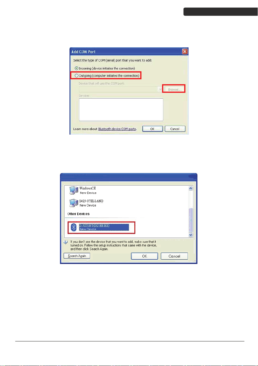
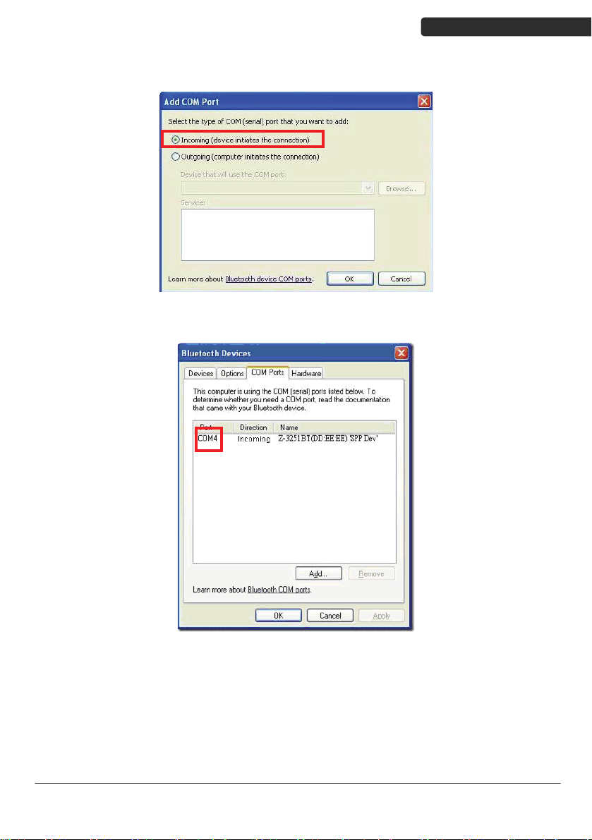
5. Select “Outgoing (computer initiate the connection)”, and then click “Browse”.
6. The scanner s
hould be on the list of discoverable devices. The default name of
the scanner is “TBD”. Select it and click “OK”.
Di Bar Watch
13
Page 24
USER’S MANUAL
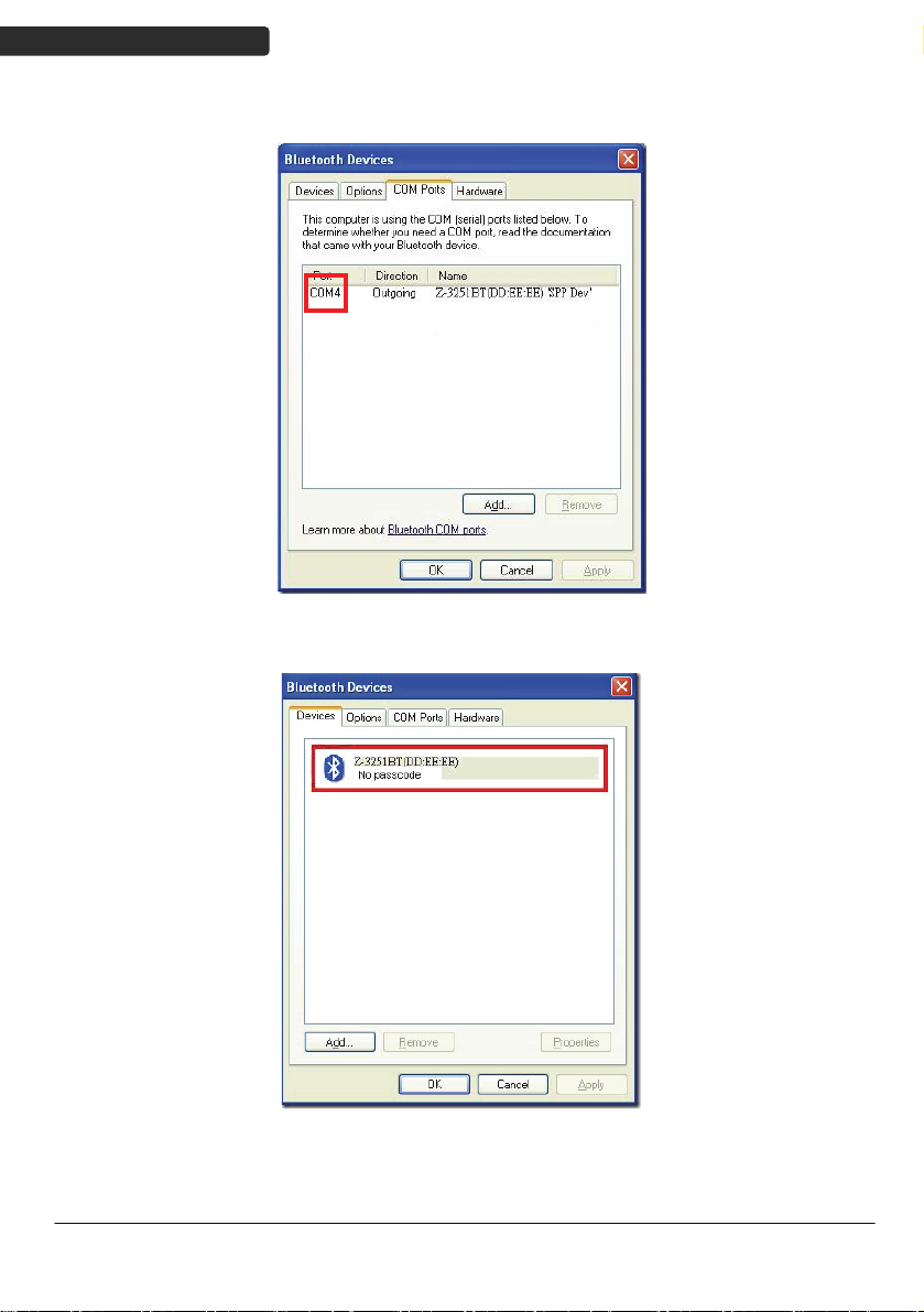
7. Write down the COM port number for later use.
8. Select t
he Device tab to go back to the device page.
14
Di Bar Watch
Page 25
USER’S MANUAL
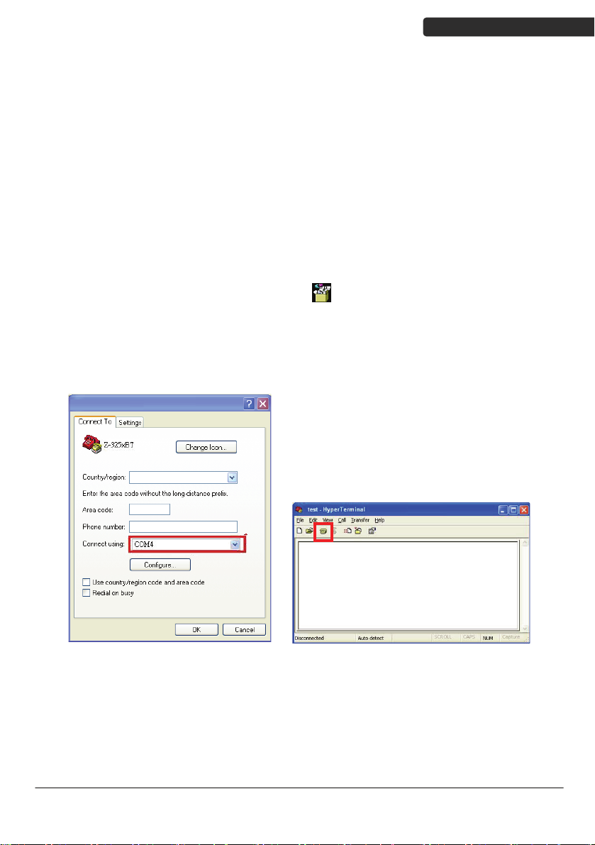
9. A message should appear in the Windows Taskbar telling you a Bluetooth
device is attempting to connect. Click on the message to open Add Bluetooth
Device Wizard.
10. Enter the pin code in the Add Bluetooth Device Wizard and click “Next”. The
default pin code is “12345678.
11. 13. Click “Ok” when the connection is established.
12. Open HyperTerminal or other serial port programs and select the COM port
you wrote down in the previous step and click “OK”.
Remark: You do not wish to proceed via HyperTerminal, you can use serial
port program by clicking icon -> [
]
13. Select the telephone icon to open the COM port.
Di Bar Watch
15
Page 26
USER’S MANUAL
SPP Master Mode
To connect a wireless device to Window XP for the first time:
1. Turn on the host computer and activate its wireless connection.
2. Select “Add wireless device”. Or open the dialog BT devices and click “Add”.
3. Power on the scanner and program it with “Scanner SPP Slave enable” label
from the previous page.
4. In COM Ports page, click “Add”. This will open the Add COM port window.
16
Di Bar Watch
Page 27
USER’S MANUAL
5. Select “Incoming (scanner initiate the connection)”, and then click “OK”.
6. Write down the COM port number for later use.
Di Bar Watch
17
Page 28

USER’S MANUAL
7. Select the Device tab to go back to the device page.
9. Scan “Set device address” to set the address.
Set device address for SPP Master
Set device address
(SPP Master only)
connection.
10. Use the ASCII table in Programming Guide to input the 12 digit device address.
For example: if the address is “011B1345600”, scan “0”, “0”, “1”, “1”, “B”, “1”,
“3”, “4”, “5”, “6”, “0”, “0” from ASCII barcode labels.
11. Scan “Confirm Setting” to store the address.
Confirm Setting (for address and pin code
setting required)
12. Setup and input the pin code if necessary. Please see Setting Pin Code section
for more details.
13. Scan “Required Pair with slave (SPP Master)” to begin pairing.
Required Pair with slave (SPP Master)
18
Di Bar Watch
Page 29

USER’S MANUAL
14. A message should appear in the Windows Taskbar telling you a Bluetooth
device is attempting to connect. Click on the message to open Add Bluetooth
Device Wizard.
15. Enter the pin code in the Add Bluetooth Device Wizard and click “Next”. The
default pin code is “12345678.
16. 13. Click “Ok” when the connection is established.
17. Open HyperTerminal or other serial port programs and select the COM port
you wrote down in the previous step and click “OK”.
Remark: You do not wish to proceed via HyperTerminal, you can use serial
port program by clicking icon -> [
]
18. Select the telephone icon to open the COM port.
Di Bar Watch
19
Page 30

USER’S MANUAL
HID mode
In HID mode, the scanner connects to the host /PC via wireless connection and performs
like there’s a keyboard connection. The scanner initiates the connection to the remote
device
1. Power on the scanner and program it with “HID Mode”. To connect a smart
mobile phone (for example, iPhone, Android), the Smart phone mode must
also be enabled. Power off the scanner when the setting is done.
2. Enable wireless connection on your host and follow the instructions in your
host to set it to discover other wireless devices in its surrounding.
3. The scanner should be on the list of discoverable devices. The default name
of the scanner is “Dibar”. You will be prompt to enter paring pin code. Select
“Dibar” and input the pin code that appears on your mobile device to
connect scanner to the phone.
4. Scan the Enter barcode to confirm. A short beep should be heard upon
connection.
HID mode
Smart phone mode
Start Of Configuration
Enable wireless HID keyboard emulation
For smart phone mode (HID MODE must also be
enabled).
Enter
Full ASCII ---CR
Function key-----“Enetr(num.)”
20
End Of Configuration
Di Bar Watch
Page 31

USER’S MANUAL
Start Of Configuration
Setting Pin Code
1. To change the pin code, use the “Set pin code” setting. Default is “12345678”.
2. Use the ASCII table in Programming Guide to input the new code (must be at
3. Scan “Save Setting” to store the pin code.
Deleting pin code
To delete pin code, use the “Delete pin code setting”.
least 4 digits and not more than 8 numeric digits).
Set pin code (SPP Master only)
Set pin code
Please check the User’s Manual from your PC for device address and pin code.
Confirm Setting (for address and pin code setting
required)
Delete the stored pin code.
Delete pin code
Reset Name
To change the scanner name back to the default name “Dibar”, use the “Default device
name” setting.
Default device name
Di Bar Watch
Change device name back to default “Dibar”.
End Of Configuration
21
Page 32

USER’S MANUAL
Start Of Configuration
Setting Name
1. To change the name displayed when the scanner is discovered, scan the
2. Use the ASCII table in Programming Guide to input the name (Max.12 digits).
3. Scan “Confirm Setting” to store the new name.
Wireless Discovery
Use the following settings to show or hide the device from wireless discovery.
Discover enable
Discover disable
“Friendly device name set” label. Default name is “Dibar”.
Change the display name when scanner is
Friendly device name set
Make scanner visible to wireless device.
Make scanner invisible to wireless device.
discovered.
Confirm Setting (for address and pin code
setting required)
22
End Of Configuration
Di Bar Watch
Page 33

USER’S MANUAL
Start Of Configuration
Secure Simple Pairing
The scanner connects to the host via SPP Slave, SPP Master, HID, HID Keyboard, or HID
Multi Media Keyboard mode without pin code when the host supports it.
Enable Apple or Android mode
For Apple or Android
Mode
SSP Enable
SSP Disable
Enable Secure Simple Pairing mode
Disable Secure Simple Pairing mode
Di Bar Watch
End Of Configuration
23
Page 34

USER’S MANUAL
Start Of Configuration
Data Transmit Method
The data transfer method includes three types: Normal (default), Out-of-Range Mode,
and Batch Mode. Users may modify this setting according to their preferences.
Normal
When the scanner is within the connection range, the scanned data will be transferred to
the host computer immediately. If the scanner is out of its connecting range, the scanner
does not send or store any data.
Out of Range
Scanned data are stored when scanner is out of its wireless communication range. When
scanner is back into its communication range or re-connected, the stored data are sent
when scanning next barcode label.
Batch mode is disabled.
Data transmit normal
Enable out of range mode.
Out of range buffer
enable
24
End Of Configuration
Di Bar Watch
Page 35

USER’S MANUAL
Start Of Configuration
Batch Mode
Whether within the connection range or not, in batch mode, the scanner stores all
scanned data that will be transferred to the host computer after scanning “Send Batch
Data” label.
Number of storable bar codes = 61,365 bytes of memory / (number of characters in the
bar code +2)
Clearing Batch
Use the settings in this section to clear the stored data.
Clear batch data after
Clear batch data by
scanning “Delete batch
Batch mode
send
data” label
Delete batch data
Note: Scanner LED indicator will not flash while waiting for
connection in this mode.
Saved data are cleared after they are transferred to the
host.
Scan this label then scan “Save Setting” to delete the
stored batch data.
Same as previous setting but with alert sound.
Confirm Setting (for address and pin code setting
required)
Di Bar Watch
End Of Configuration
25
Page 36

USER’S MANUAL
Start Of Configuration
Batch Transfer
Use the settings in this section to setup batch transfer.
Send Batch Data By
Send Batch Data on line
USB cable contact
Batch Mode Sounds Settings
Use the settings in this section to setup the sound.
Out of range resend data
with beeper sound
Out of range resend data
without beeper sound in
Out of range mode.
Send Batch Data without
Send Batch Data with Beep
Scanning Label
beep
Scanning this label automatically exits you from the
Programming Mode. Press and hold the trigger for over
1 second to send the data.
Data is ready to be transferred upon USB connection.
Press and hold the trigger for over 1 second to send
the data.
Add beeper sound when resending data in Out of range
mode.
No beeper sound when resending data
No beep when sending data. Good-read LED will light
up until the transfer is done.
Beep sound when sending data. Good-read LED will
light up until the transfer is done.
26
End Of Configuration
Di Bar Watch
Page 37

System Function Settings
Default values are highlighted in grey background.
Barcode Value Description
Start Of Configuration
Return scanner to factory defaults
Return dongle host to factory defaults
Return to USB default
(Communication dongle link required)
Return as USB-virtual COM port default
(Communication dongle link required)
Return as OPOS port default
USER’S MANUAL
Di Bar Watch
Function Button Enable
Enable the function/off button
Function Button Disable
Disable the function/off button
End Of Configuration
27
Page 38

USER’S MANUAL
Start Of Configuration
Barcode Value Description
Display firmware version
Scan Mode
Abort
(exit programming mode without any updates)
Tri gger mode
The scanner becomes inactive as soon as the data is
transmitted. It must be triggered to become active again.
Auto scan mode
The scanner is still active after the data is transmitted but
the successive transmission of the same barcode is not
allowed when the trigger switch is pressed again.
Alternate mode
The scanner illumination alternates between on and off
when the trigger switch is pressed.
Presentation mode
Also called auto trigger mode. The scanner is inactive but
will automatically detect barcodes presented in the scan
zone and become active.
Idle mode enable
Idle mode disable
Disable Idle mode.
28
End Of Configuration
Di Bar Watch
Page 39

Start Of Configuration
Radio Communication Setting
Dongle Host mode
Dongle Host mode enable
Enable dongle mode with this setup.
USER’S MANUAL
Unlock pairing mode
In this mode, the scanner can pair with another dongle
when disconnected.
Lock pairing mode.
In this mode, the scanner can not pair with another
dongle.
Undo pairing
Undo the pairing between the dongle and the scanner.
USB Online mode
USB online scan disable
USB online scan enable
USB online scan, Ignore radio communication
Di Bar Watch
End Of Configuration
29
Page 40

USER’S MANUAL
Start Of Configuration
HID mode
HID mode (Combo keyboard)
For Apple mode
SPP Master/Slave mode
Scanner SPP Master enable
SPP Master (Connect wireless address
“BxxxxxxxxxxxxT” in CODE39 format)
Scanner SPP Slave enable
Setting wireless address (SPP Master only)
Set PIN code (SPP Master only)
Device Setting
Show device address after friendly name enabled
Enable showing device address xx:xx:xx after device
name during discovery
Show device address after device friendly name
disabled
Disable showing device address xx:xx:xx after device
name during discovery
30
End Of Configuration
Di Bar Watch
Page 41

USER’S MANUAL
Start Of Configuration
Default Device name
Friendly device name set
Delete pin code
Confirm Setting (for address, device name, and pin
code setting required)
Required Pair with slave (SPP Master)
Discover enable
Discover disable
Encryption enable
Encryption disable
Data communication without protocol
Data communication with ACK/NAK protocol
Di Bar Watch
Data communication with Packing protocol
End Of Configuration
31
Page 42

USER’S MANUAL
Start Of Configuration
Data Transmit Mode
Data transmit normal
Out of range buffer enable
Batch mode
Send Batch Data By Scanning Label
Clear batch data after send
Clear batch data by scanning “Delete batch data” label
Delete batch data
32
Send Batch Data on line USB cable contact.
Send Batch data on dongle
Out of range resend data with beeper sound
Out of range resend data without beeper sound
Send Batch Data without Beep
Send Batch Data with Beep
End Of Configuration
Di Bar Watch
Page 43

USER’S MANUAL
Start Of Configuration
Radio protocol communication parameter
Radio protocol timeout= 3 sec
Radio protocol timeout= 5 sec
Radio protocol timeout =8 sec
Radio protocol timeout= 10 sec
Radio protocol timeout =13 sec
Di Bar Watch
Radio protocol timeout =16 sec
Radio protocol timeout= 20 sec
End Of Configuration
33
Page 44

USER’S MANUAL
Start Of Configuration
Power off timeout parameter
Power off timeout=5 min
Power off timeout=10 min
Power off timeout=20 min
Power off timeout=30 min
Power off timeout=1 hr
Power Off timeout : 2 hr
Power Off timeout : 4 hr
Power Off timeout : 6 hr
Power Off timeout : 8 hr
34
End Of Configuration
Di Bar Watch
Page 45

USER’S MANUAL
Start Of Configuration
Power Always On
Power off by scanning this label
Link beeper enable
Link beeper disable
Power-up beeper enable
Power-up beeper disable
Same Code Delay
50 msec
100 msec
200 msec
300 msec
Di Bar Watch
End Of Configuration
35
Page 46

USER’S MANUAL
Start Of Configuration
400 msec
500 msec
600 msec
700 msec
800 msec
1000 msec
Infinite
36
End Of Configuration
Di Bar Watch
Page 47

Start Of Configuration
Operation Function Setting
Good Read Beeper Tone Selection
Medium beeper tone
USER’S MANUAL
High beeper tone
Low beeper tone
Speaker disable
Di Bar Watch
End Of Configuration
37
Page 48

USER’S MANUAL
Start Of Configuration
Beeper duration Selection
Long
Medium
Short
Ultra Short
Ultra Long
38
End Of Configuration
Di Bar Watch
Page 49

USER’S MANUAL
Start Of Configuration
Inter Character Delay
0 ms
2 ms
5 ms
10 ms
20 ms
50 ms
Inter Message Delay
0 ms
Di Bar Watch
100 ms
500 ms
1000 ms
End Of Configuration
39
Page 50

USER’S MANUAL
Interface Settings
RS-232C Interface Setting
Start Of Configuration
Start Of Configuration
Message Terminator
RS-232 message terminator—none
RS-232 message terminator—CR/LF
RS-232 message terminator—CR
RS-232 message terminator—LF
RS-232 message terminator—H tab
40
RS-232 message terminator—STX/ETX
RS-232 message terminator—EOT
End Of Configuration
Di Bar Watch
Page 51

USB Interface Setting
Start Of Configuration
etting
USB S
International Keyboard mode ( ALT method)
Keyboard language support---USA
Keyboard language support---UK send scan code
Keyboard language support---GERMANY
Keyboard language support---FRENCH send scan
code
Keyboard language support---SPANISH send scan
code
Keyboard language support---ITALIAN send scan
code
Keyboard language support---Switzerland send scan
code
Keyboard language support---Belgium send scan
code
Keyboard language support---Japanese
Capital lock on
Capital lock off
Function key emulation enable
Function key emulation disable
Send number as normal data
Send number as keypad data
USER’S MANUAL
Di Bar Watch
End Of Configuration
41
Page 52

USER’S MANUAL
Start Of Configuration
Message Terminator
Keyboard terminator---none
Keyboard terminator---Enter
Keyboard terminator---H-TAB
42
End Of Configuration
Di Bar Watch
Page 53

USER’S MANUAL
Start Of Configuration
Smart Phone Soft re Keypad Control Setting
To enable/disable Software keyboard:
1. Scan the Start Of Configuration b
. Scan the Multi-media keyboard mode barcode.
2
3. Scan the End Of Configuration barcode.
4. Connect the scanner with a smart phone. Please
5. W
Mass-Storage Model Set
ith Multi-media keyboard mode enabl
may scan the Software keypad enable/disable barcode to enable or disable the
Software keypad.
wa
Smart Phone Software Ke
Multi-me
This option enables Multi-
are key
Softw
This option enable or disable Software
ting
Ma
ypad Control
dia keyboard mode
mode
pad enable/disable
ke
ypad
arcode.
ed and smart phone connection made, you
ss-Storage Mode
media keyboard
see HID mode for instructions.
Di Bar Watch
M ble
ass-Storage mode ena
End Of Configuration
43
Page 54

USER’S MANUAL
he Symbologies
T
Start Of Configuration
Codabar Parameter Settin
Barcode
Value
RC02
RD02 Codabar disable
CB05 Codabar start/stop character transmissionnone
CB06
CB07
CB08
CB09
CB10
Barcode Lab
g
el Description
Codabar enable
Codabar start/stop character transmission A,B,C, D
Codabar start/stop character transmission
DC1~DC4
Codabar start/stop character transmission
a/t,b/n,c/*,d/e
Codabar maximum length setting
Codabar minimum length setting
44
SET
Confirm to save this setting (required for reading full
ASCII table and length setting)
End Of Configuration
Di Bar Watch
Page 55

Barcode
Value
CB13
USER’S MANUAL
Start Of Configuration
Barcode Label Description
No check character
CB14
CB15
DC50
DC51
DC52
DC53
Validate modulo 16,but don’t transmit
Validate modulo 16 and transmit
Codabar data redundant check=off
Codabar data redundant check=1
Codabar data redundant check=2
Codabar data redundant check=3
Di Bar Watch
End Of Configuration
45
Page 56

USER’S MANUAL
Code 39 Paramete etting
Barcode
Value
1
RC0
r S
Barcode Lab
Start Of Configuration
el Description
Code 39 enable
RD01
RC13
RD13
DC00
DC01
DC02
DC03
3901
3902
Code 39 disable
Code 32 enable
Code 32 disable
Code 39 data redundant check=off
Code 39 data redundant check=1
Code 39 data redundant check=2
Code 39 data redundant check=3
Standard code 39
Full ASCII code 39
46
3903
3904
Code 39 start/stop character transmission
Code 39 start/stop character without transmission
End Of Configuration
Di Bar Watch
Page 57

Barcode
Value
3905
USER’S MANUAL
Start Of Configuration
Barcode Label Description
Code 39 check digit c transmit alculate and
3906
3907
3908
3909
SET
39 2 1 Code 32 (Italian pharmacy) transmit “A” character
3913
Code 39 check digit calculate but without transmit
No check character
Code 39 maximum length setting
Code 39 minimum length setting
Confirm to save this setting (required for reading full
ASCII table and length setting)
Code 32 (Italian pharmacy) without transmit ”A”
character
Di Bar Watch
End Of Configuration
47
Page 58

USER’S MANUAL
Code 93 Paramete etting
Barcode
Value
8
RC0
r S
Barcode Lab
Start Of Configuration
el Description
Code 93 enable
RD08
DC30
DC31
DC32
DC33
9301
9302
SET
9303 Code 93 check digit calculate but without transmit
Code 93 disable
Code 93 data redundant check=off
Code 93 data redundant check=1
Code 93 data redundant check=2
Code 93 data redundant check=3
Code 93 maximum length setting
Code 93 minimum length setting
Confirm to save this setting (required for reading full
ASCII table and length setting)
48
9304
9305
Code 93 check digit not calculate and without
transmit
Code 93 check digit calculate and transmit
End Of Configuration
Di Bar Watch
Page 59

Code 128 Paramet ttin
Barcode
Value
6
RC0
er Se g
Barcode Labe
USER’S MANUAL
Start Of Configuration
l Description
Code 128 enable
RD06
RC10
RD10
DC40
DC41
DC42
DC43
1803
1804
1805
1806
1807
Code 128 disable
EAN-128 enable
EAN-128 disable
Code 128 data redundant check=off
Code 128 data redundant check=1
Code 128 data redundant check=2
Code 128 data redundant check=3
No check character
Calculate but not transmit
Calculate and transmit
Code 128 maximum length setting
Code 128 minimum length setting
SET
Di Bar Watch
Confirm to save this setting (required for reading full
ASCII table and length setting)
End Of Configuration
49
Page 60

USER’S MANUAL
Chinese Post Code Paramet
Barcode
Value
RC05
Barcode Label
Start Of Configuration
er Setting
Chinese post code en
Description
able
RD05
DC60
DC61
DC62
DC63
SZ01
SZ02
SET
Chinese post code disable
Chinese post code data redundant check=off
Chinese post code data redundant check=1
Chinese post code data redundant check=2
Chinese post code data redundant check=3
Chinese post code maximum length setting
Chinese post code minimum length setting
Confirm to save this setting (required for reading full
ASCII table and length setting)
50
End Of Configuration
Di Bar Watch
Page 61

MSI/Plessy Parame r Setti
Barcode
Value
RC14
te ng
Barcode Label
USER’S MANUAL
Start Of Configuration
Description
MSI enable
RD14
DC70
DC71
DC72
DC73
MS01
MS02
SET
M S03 MSI/Plessy double check digit calculate but not
MS04
MS05
MS06
MS07
MS08
MSI disable
MSI data redundant check= off
MSI data redundant check=1
MSI data redundant check=2
MSI data redundant check=3
MSI/Plessy maximum length setting
MSI/Plessy minimum length setting
Confirm to save this setting (required for reading full
ASCII table and length setting)
transmit
MSI/Plessy double check digit without calculate
transmit
MSI/Plessy double check digit calculate but only first
digit transmit
MSI/Plessy double check digit calculate and both
transmit
MSI/Plessy single check digit calculate but without
transmit
MSI/Plessy single check digit calculate and transmit
and
Di Bar Watch
End Of Configuration
51
Page 62

USER’S MANUAL
Code 11 Interface Setting
Barcode
Value
RC07
Barcode La
Start Of Configuration
bel Description
Code 11 enable
RD07
1101
1102
SET
1103 Code 11 one check digit verification
1104
1105
1106
1107
Code 11 disable
Code 11 maximum length setting
Code 11 minimum length setting
Confirm to save this setting (required for reading full
ASCII table and length setting)
Code 11 two check digit verification
Two Check for Code 11 check digit if code length is
longer than 10 characters
Disable verification
Code 11 check digit transmitted
52
1108
Code 11 check digit not transmitted
End Of Configuration
Di Bar Watch
Page 63

ITF 2 of 5 Paramet etting
Barcode
Value
4
RC0
er S
Barcode Labe
USER’S MANUAL
Start Of Configuration
l Description
ITF 2 of 5 enable
RD04
RC09
RD09
DC80
DC81
DC82
DC83
IT03
IT04
ITF 2 of 5 disable
IATA code enable
IATA disable
ITF 25 data redundant check=off
ITF25 data redundant check=1
ITF25 data redundant check=2
ITF25 data redundant check=3
ITF 2 of 5 no check character
ITF 2 of 5 check digit calculate and transmit
IT05
Di Bar Watch
ITF 2 of 5 check digit calculate but without transmit
End Of Configuration
53
Page 64

Barcode
Value
IT01
USER’S MANUAL
Start Of Configuration
Barcode Label Description
ITF 2 of 5 code maximum leng ting
th set
IT02
IT06
IT07
SET
ITF 2 of 5 code minimum length setting
ITF 2 of 5 one fixed length setting
ITF 2 of 5 two fixed length setting
Confirm to save this setting (required for reading full
ASCII table and length setting)
ITF 2 of 5 length variable IT08
54
End Of Configuration
Di Bar Watch
Page 65

Standard 2 of 5 Pa meter
Barcode
Value
RC22
ra Setting
Barcode Label
Start Of Configuration
Standard 2 of 5 code e
USER’S MANUAL
Description
nable
RD22
D051
D052
SET
D054
D055
Standard 2 of 5 code disable
Standard 2 of 5 code maximum length setting
Standard 2 of 5 code minimum length setting
Confirm to save this setting (required for reading full
ASCII table and length setting)
Standard 2 of 5 code no check cD053 haracter
Standard 2 of 5 code check digit calculate and
transmit
Standard 2 of 5 code check digit calculate but
without transmit
Di Bar Watch
End Of Configuration
55
Page 66

USER’S MANUAL
Industrial 2 of 5 Pa meter
Barcode
Value
RC21
ra Setting
Barcode Label
Start Of Configuration
Industrial 2 of 5 code e
Description
nable
RD21
D251
D252
SET
D254
D255
Industrial 2 of 5 code disable
Industrial 2 of 5 code maximum length setting
Industrial 2 of 5 code minimum length setting
Confirm to save this setting (required for reading full
ASCII table and length setting)
Industrial 2 of 5 code no check D253 character
Industrial 2 of 5 code check digit calculate and
transmit
Industrial 2 of 5 code check digit calculate but
without transmission
56
End Of Configuration
Di Bar Watch
Page 67

UPC/EAN/JAN Para eter Se
Barcode
Value
RC11
m tting
Barcode Label
USER’S MANUAL
Start Of Configuration
Description
EAN convert to ISSN/ISBN enable
RD11
RC03
RD03
UE01
UE02
UE03
UE04
UE05
UE06
UE07
EAN convert to ISSN/ISBN disable
UPC/EAN/JAN enable
UPC/EAN/JAN disable
UPC/EAN/JAN all enable
EAN-8 or EAN-13 enable
UPC-A and EAN-13 enable
UPC-A and UPC-E enable
UPC-A enable
UPC-E enable
EAN-13 enable
UE08
UE09
Di Bar Watch
EAN-8 enable
UPC/EAN Addendum disable
End Of Configuration
57
Page 68

Barcode
Value
UE10
USER’S MANUAL
Start Of Configuration
Barcode Label Description
Add on 5 only
UE11
UE12
UE13
UE14
UE15
UE16
UE44
UE45
UE17
UE18
UE19
Add on 2 only
Add on 2 or 5
Force UPC-E to UPC-A format enable
Force UPC-E to UPC-A format disable
Force UPC-A to EAN-13 format enable
Force UPC-A to EAN-13 format disable
Force EAN-8 to EAN-13 format enable
Force EAN-8 to EAN-13 format disable
Transmit UPC-A check digit enable
Transmit UPC-A check digit disable
Transmit UPC-E leading character enable
58
UE20
UE21
UE22
Transmit UPC-E leading character disable
Transmit UPC-E check digit enable
Transmit UPC-E check digit disable
End Of Configuration
Di Bar Watch
Page 69

Barcode
Value
UE23
USER’S MANUAL
Start Of Configuration
Barcode Label Description
Transmit EAN-8 check digit enable
UE24
UE25
UE26
UE27
UE28
UE30
UE31
UE60
UE61
UE66
Transmit EAN-8 check digit disable
Transmit EAN-13 check digit enable
Transmit EAN-13 check digit disable
Transmit UPC-A leading character enable
Transmit UPC-A leading character disable
Add-on format with separator
Add-on format without separator
EAN-13 country code first “0” can be transmitted
EAN-13 country code first:”0” can’t be transmitted
EAN-13 with first 0 ID code same as “UPC-A”
UE67
DC10
DC11
Di Bar Watch
EAN-13 with first 0 ID code same as “EAN-13”
UPC-A data redundant check=off
UPC-A data redundant check=1
End Of Configuration
59
Page 70

Barcode
Value
DC12
USER’S MANUAL
Start Of Configuration
Barcode Label Description
UPC-A data redundant check=2
DC13
DC14
DC15
DC16
DC17
DC20
DC21
DC22
DC23
DC24
DC25
DC26
UPC-A data redundant check=3
UPC-E data redundant check=off
UPC-E data redundant check=1
UPC-E data redundant check=2
UPC-E data redundant check=3
EAN-13 data redundant check=off
EAN-13 data redundant check=1
EAN-13 data redundant check=2
EAN-13 data redundant check=3
EAN-8 data redundant check=off
EAN-8 data redundant check=1
EAN-8 data redundant check=2
60
DC27
UE32
UE33
EAN-8 data redundant check=3
EAN/UPC +add-on (none mandatory)
EAN/UPC +add-on (mandatory)
End Of Configuration
Di Bar Watch
Page 71

UE35
USER’S MANUAL
Start Of Configuration
EAN/UPC +add-on mandatory for 978/977 bookland
(Supplement requirement, not sent for other)
UE38
UE42
EAN/UPC +addon mandatory for 978/977 bookland
(Supplement requirement, optional for other)
EAN/UPC +addon mandatory for 491 Japanese
bookland
UE43
EAN/UPC +addon mandatory 491 Japanese book
(Supplement requirement, optional for other)
(Supplement requirement, not sent for other)
land
Di Bar Watch
End Of Configuration
61
Page 72

USER’S MANUAL
Telepen Paramete tting
Barcode
Value
RC25
r Se
Barcode Lab
Start Of Configuration
el Description
Telepen enable
RD25
TE03
TE04
Telepen disable
Telepen numeric mode enable
AIM Telepen enable
62
End Of Configuration
Di Bar Watch
Page 73

Matrix 2 of 5 Parameter Set
Barcode
Value
RC12
Barcode Label
USER’S MANUAL
Start Of Configuration
ting
Description
Matrix 2 of 5 enable
RD12
D151
D152
SET
D154
D155
Matrix 2 of 5 disable
Matrix 2 of 5 maximum length setting
Matrix 2 of 5 minimum length setting
Confirm to save this setting (required for reading full
ASCII table and length setting)
Matrix 2 of 5 no check characteD153 r
Matrix 2 of 5 check digit calculate and transmit
Matrix 2 of 5 check digit calculate but without
transmission
Di Bar Watch
End Of Configuration
63
Page 74

USER’S MANUAL
Start Of Configuration
GS1 DataBar Param ter Set
There are 7 kinds of barcodes in
ee groups. Barcode types in the same group use the same barcodes for setting.
th
r
Group Representative Contents
Group 1 GS1 DataBar Omnidirectional
Group 2 GS1 DataBar Limited
Group 3 GS1 DataBar Expanded d
Barcode
Value
RC15
e ting
the GS1 DataBar family and they are categorized into
GS1 DataBar Omnidirectional
(F
ormally RSS-14) ar Truncated
(Formally RSS Limited)
GS1 DataBar Omnidirectio
Barcode
Label Description
GS1 DataBar Omnidirectional enable
GS1 DataB
taBar Stacked
GS1 Da
GS1 DataBar Stacked Om
GS1 DataBar Limited
GS1 DataBar Expande
GS1 DataBar Expande
nal (Formally RSS-14)
nidirectional
d Stacked (Formally RSS Expanded)
RD15
SS00
SS01
SS02
SS03
SS05
SS04 GS1 DataBar Omnidirectional /EAN-128 emulation
64
End Of Configuration
GS1 DataBar Omnidirectional disable
Transmit GS1 DataBar Omnidirectional check digit
Do not transmit GS1 DataBar Omnidirectional check
digit
Transmit GS1 DataBar Omnidirectional application ID
(01)
Do not transmit GS1 DataBar Omnidirectional
application ID (01)
GS1 DataBar Omnidirectional /EAN-128 emulat
enable
disable
Di Bar Watch
ion
Page 75

Barcode
Value
RC16
Start Of Configuration
GS1 DataBar Limited (Formally RSS Limited)
Barcode
Label Description
GS1 DataBar Limited ena
USER’S MANUAL
ble
RD16
SS10
SS11
SS12
SS13
GS1 DataBar Limited disable
Transmit GS1 DataBar Limited check digit
Don’t transmit GS1 DataBar Limited check digit
Transmit GS1 DataBar limited application ID (01)
Do not transmit GS1 DataBar limited application ID
Di Bar Watch
End Of Configuration
65
Page 76

Barcode
Value
RC17
USER’S MANUAL
GS1 DataBar Expanded (Formally RSS Expanded)
Barcode
Start Of Configuration
Label Description
GS1 DataBar Expanded
enable
RD17
SS07
SS06
SS08
SS09
SS16
SS17
GS1 DataBar Expanded disable
GS1 DataBar Expanded/EAN-128 emulation enable
GS1 DataBar Expanded/EAN-128 emulation disable
GS1 DataBar Expanded check digital enable
GS1 DataBar Expanded check digital disable
Transmit GS1 DataBar Expanded application ID (01)
Do not transmit GS1 DataBar Expanded application
ID
66
End Of Configuration
Di Bar Watch
Page 77

Start Of Configuration
Data Editing
Identifier Code
Barcode
Value
IS00 Disable identifier code
Barcode
Label Description
USER’S MANUAL
IS01
IS03
CI01
CI02
CI03
CI04
CI05
CI06
CI07
Enable identifier code table as factory standard
Enable identifier code table as AIM standard.
Code 39 identifier code setting
ITF 2 of 5 identifier code setting
Chinese Post Code identifier code setting
UPC-E identifier code setting
UPC-A identifier code setting
EAN-13 identifier code setting
EAN-8 identifier code setting
SET
Di Bar Watch
Confirm to save this setting (required for reading full
ASCII table and length setting)
End f C O onfiguration
67
Page 78

Barcode
Value
CI08
USER’S MANUAL
Start Of Configuration
Barcode Label Description
Codabar identifier co
de setting
CI09
CI10
CI11
CI12
CI13
CI14
CI15
CI16
CI17
Code 128 identifier code setting
Code 93 identifier code setting
MSI identifier code setting
GS1 DataBar Omnidirectional identifier code setting
GS1 DataBar Limited identifier code setting
GS1 DataBar expanded identifier code setting
Industrial 2 of 5 identifier code setting
Code 11 Identifier code setting
Standard 2 of 5 identifier code setting
68
CI18
SET
Matrix 2 of 5 identifier code setting
Confirm to save this setting (required for reading full
ASCII table and length setting)
End f C O onfiguration
Di Bar Watch
Page 79

Header and Traile
Barcode
Value
CP11
r
Barco
Start Of Configuration
de Label Description
Add code length as h 2 digits)
eader enable (
USER’S MANUAL
CP12
HT01
HT02
HT03
HT04
SET
Add code length as header disable (2 digits)
Header (Preamble)
Trailer (Postamble)
Truncate header character
Truncate trailer character
Confirm to save this setting (required for reading full
ASCII table and length setting)
Di Bar Watch
End Of Configuration
69
Page 80

USER’S MANUAL
Full ASCII Code 3 able
Code 39 ASCII
9 T
Full ASCII ---NUL 00
Full ASCII ---SOH
Function key-----“Ins”
Full ASCII ---STX
Function key-----“Del”
Full ASCII ---ETX
Function key-----“Home”
Full ASCII ---EOT
Function key-----“End”
Full ASCII ---ENQ
Function key-----“Up
arrow”
Full ASCII ---ACK
Function key-----“Down
arrow”
Full ASCII ---BEL
Function key-----“Left
arrow”
Full ASCII ---BS
Function key----“Backspace”
Full ASCII ---HT
Function key-----“TAB”
Full ASCII ---LF
Function key-----“Enter
(alpha numeric)”
Full ASCII ---VT
Function key-----“right
arrow”
Full ASCII ---FF
Function key-----“PgUp”
Full ASCII ---CR
Function key----“Enetr(num.)”
Full ASCII ---SO
Function key-----“PgDn”
Start Of Configuration
Hexa
-
Code 39 ASCII
code
01
02
03
04
05
06
07
08
09
0A
0B
0C
0D
0E
Full ASCI
I ---SI
Functio Shift”
n key-----“
Full ASCII ---DLE
Function key----“5(num)”
Full ASCII ---DC1
Function key-----“F1”
Full ASCII ---DC2
Function key-----“F2”
Full ASCII ---DC3
Function key-----“F3”
Full ASCII ---DC4
Function key-----“F4”
Full ASCII ---NAK
Function key-----“F5”
Full ASCII ---SYN
Function key-----“F6”
Full ASCII ---ETB
Function key-----“F7”
Full ASCII ---CAN
Function key-----“F8”
Full ASCII ---EN
Function key-----“F9”
Full ASCII ---SUB
Function key-----“F10”
Full ASCII ---ESC
Function key-----“F11”
Full ASCII ---FS
Function key-----“F12”
Full ASCII ---GS
Function key-----“ESC”
Hexa-
code
0F
10
11
12
13
14
15
16
17
18
19
1A
1B
1C
1D
70
End Of Configuration
Di Bar Watch
Page 81

Start Of Configuration
Full ASCII Code 3 able (c9 T ontinued)
Code 39 ASCII
Full ASCII ---RS
Function TL(L)” key-----“C
Full ASCII ---US
Function key-----“ALT(L)”
Full ASCII ---SP 20
Full ASCII ---! 21
Full ASCII ---“ 22
Full ASCII ---# 23
Full ASCII ---$ 24
Full ASCII ---% 25
Full ASCII ---& 26
Full ASCII ---‘ 27
Full ASCII --- ( 28
Full ASCII ---) 29
Full ASCII ---* 2A
Full ASCII ---+ 2B Full ASCII ---: 3A
Full ASCII ---, 2C Full ASCII ---; 3B
Hexa-
de
co
1E
1F
Code 39 ASCII
Full ASCII ---- 2D
Full ASCII ---. 2E
Full ASCII ---/ 2F
Full ASCII ---0 30
Full ASCII ---1 31
Full ASCII ---2 32
Full ASCII ---3 33
Full ASCII ---4 34
Full ASCII ---5 35
Full ASCII ---6 36
Full ASCII ---7 37
Full ASCII ---8 38
Full ASCII ---9 39
USER’S MANUAL
Hexa-
code
Di Bar Watch
End Of Configuration
71
Page 82

USER’S MANUAL
Start Of Configuration
Full ASCII Code 39 Table (continued)
Code 39 ASCII
Full ASCII ---<
Full ASCII ---=
Full ASCII --->
Full ASCII ---?
Full ASCII ---@
Full ASCII ---A 41
Full ASCII ---B 42
Full ASCII ---C 43
Full ASCII ---D 44
Full ASCII ---E 45
Full ASCII ---F 46
Full ASCII ---G 47
Full ASCII ---H 48
Full ASCII ---I 49
Full ASCII ---J 4A
Hexa-
cod
3C
3D
3E
3F
40
Code 39 ASCII
e
Fu
ll ASCII ---K
Full ASCII ---L
Full ASCII ---M
Full ASCII ---N
Full ASCII ---O
Full ASCII ---P 50
Full ASCII ---Q 51
Full ASCII ---R 52
Full ASCII ---S 53
Full ASCII ---T 54
Full ASCII ---U 55
Full ASCII ---V 56
Full ASCII ---W 57
Full ASCII ---X 58
Full ASCII ---Y 59
Hexa-
code
4B
4C
4D
4E
4F
72
End Of Configuration
Di Bar Watch
Page 83

Start Of Configuration
Full ASCII Code 39 Table (continued)
Code 39 ASCII
Full ASCII ---Z 5A
Full ASCII ---[ 5B
Full ASCII ---\ 5C
Full ASCII ---] 5D
Full ASCII ---^ 5E
Full ASCII ---_ 5F
Full ASCII ---` 60
Full ASCII ---a 61
Full ASCII ---b 62
Full ASCII ---c 63
Full ASCII ---d 64
Full ASCII ---e 65
Full ASCII ---f 66
Full ASCII ---g 67
Full ASCII ---h 68
Hexa-
cod
Code 39 ASCII
e
USER’S MANUAL
Hexa-
code
Full ASCII ---i 69
Full ASCII ---j 6A
Full ASCII ---k 6B
Full ASCII ---l 6C
Full ASCII ---m 6D
Full ASCII ---n 6E
Full ASCII ---o 6F
Full ASCII ---p 70
Full ASCII ---q 71
Full ASCII ---r 72
Full ASCII ---s 73
Full ASCII ---t 74
Full ASCII ---u 75
Full ASCII ---v 76
Full ASCII ---w 77
Di Bar Watch
End Of Configuration
73
Page 84

USER’S MANUAL
Start Of Configuration
Full ASCII Code 39 Table (continued)
Code 39 ASCII
Full ASCII ---x 78
Full ASCII ---y 79
Full ASCII ---z 7A
Full ASCII ---{ 7B
Hexa-
cod
Code 39 ASCII
e
Full ASCII ---| 7C
Full ASCII ---} 7D
Full ASCII ---~ 7E
Full ASCII ---DEL
Hexa-
code
7F
74
End Of Configuration
Di Bar Watch
Page 85

USER’S MANUAL
Appendix 1: SB V er Installation
Contact your distributor to get the driver and follow the steps below to enable USB
virtual COM port.
1. Connect the handheld scanner and the host (e.g. a PC) with a USB interface cable.
2. Enable USB virtual COM port with programming barcode on page 32.
3. After the programming, the host would request driver installation. Browse your
files to locate the driver and start installation.
4. The USB virtual COM port is ready for use after driver installation.
U irtual COM Driv
Di Bar Watch
75
Page 86

USER’S MANUAL
g
p
Appendix 2: Barcode Length Setting
Introduction
The length of a barcode is the number of characters it contains, including check digits.
As listed in the Default Parameters section, each barcode type has different default
length. You may change the setting by the following procedure.
To set up barcode length, the paramours to be determined are barcode type and the
desired barcode length. Barcode length is consisted of 2 digits. For numbers smaller
than 10, you need to add a “0” in the front.
Example
If the barcode length is 4 to 12 digits, the steps would be as below:
Start Set up barcode length End
Start of Configuration End of Configuration
Set up minimum Set up maximum
barcode length barcode length
Scan the “Start of
config ation” barcode
ur
Read e “Full ASCII
th
co 9” barcode
de 3
Turn to the page of the
barcode type to be set
u
Scan the
“Min“ bar
Scan the first
digit: 0
Scan the second
digit: 4
code
Set the “Max”
code
bar
Set up the first
digit: 1
Set up the
second digit: 2
Scan the “Se
barcode to save this
Scan the “End of
nfiguration”
co
t”
settin
barcode
Use the ASCII table (Appendix 4) to set up barcode length. Be sure to enable
the full ASCII code 39 option before you start and read the “Set” label to set
your choice into memory.
76
Di Bar Watch
Page 87

Federal Communication Commission Interference Statement
This equipment has been tested and found to comply with the limits for a Class B
digital device, pursuant to Part 15 of the FCC Rules. These limits are designed to
provide reasonable protection against harmful interference in a residential installation.
This equipment generates, uses and can radiate radio frequency energy and, if not
installed and used in accordance with the instructions, may cause harmful interference
to radio communications. However, there is no guarantee that interference will not
occur in a particular installation. If this equipment does cause harmful interference
to radio or television reception, which can be determined by turning the equipment off
and on, the user is encouraged to try to correct the interference by one of the
following measures:
z Reorient or relocate the receiving antenna.
z Increase the separation between the equipment and receiver.
z Connect the equipment into an outlet on a circuit different from that to which
the receiver is connected.
z Consult the dealer or an experienced radio/TV technician for help.
15.21
FCC Caution: Any changes or modifications not expressly approved by the party
responsible for compliance could void the user's authority to operate this equipment.
15.19
This device complies with Part 15 of the FCC Rules. Operation is subject to the
following two conditions: (1) This device may not cause harmful interference, and (2)
this device must accept any interference received, including interference that may
cause undesired operation.
FCC RF Radiation Exposure Statement:
1. This Transmitter must not be co-located or operating in conjunction with any other
antenna or transmitter.
2. This equipment complies with FCC RF radiation exposure limits set forth for an
uncontrolled environment.
 Loading...