

Page 1
802.11n 2.4G WLAN
Customer Premises Equipment
Quick Installation Guide
V1.0 August 2009
Page 2
Copyright
Copyright © 2009 all rights reserved. No part of this publication may be reproduced, adapted,
stored in a retrieval system, translated into any language, or transmitted in any form or by any
means without the written permission of the supplier.
About the Quick Installation Guide
This Quick Installation Guide is intended to guide professional installer to install the
IEEE802.11n
problems.
Wireless CPE. It covers procedures to assist you in avoiding unforeseen
Conventions
Warning:
This sign indicates a warning or caution that you have to abide.
Note:
This sign indicates an important note that you must pay attention to.
Page 3
FCC Information
This device complies with Part 15 of the FCC Rules. Operation is subject to the
following two conditions: (1) this device may not cause harmful interference, and (2)
this device must accept any interference received; including interference that may
cause undesired operation.
Federal Communications Commission (FCC) Statement
This Equipment has been tested and found to comply with the limits for a Class B
digital device, pursuant to Part 15 of the FCC rules. These limits are designed to
provide reasonable protection against harmful interference in a residential installation.
This equipment generates uses and can radiate radio frequency energy and, if not
installed and used in accordance with the instructions, may cause harmful
interference to radio communications. However, there is no guarantee that
interference will not occur in a particular installation. If this equipment does cause
harmful interference to radio or television reception, which can be determined by
turning the equipment off and on, the user is encouraged to try to correct the
interference by one or more of the following measures:
- Reorient or relocate the receiving antenna.
- Increase the separation between the equipment and receiver.
- Connect the equipment into an outlet on a circuit different from that to which the
receiver is connected.
-Consult the dealer or an experienced radio/TV technician for help.
Warning: Any changes or modifications to this unit not expressly approved by
the party responsible for compliance could void the user authority to operate
the equipment.
Trade name
Model number
FCC RF Radiation Exposure Statement:
1. This Transmitter must not be co-located or operating in conjunction with any
other antenna or transmitter.
Page 4

2. This equipment complies with FCC RF radiation exposure limits set forth for an
uncontrolled environment. This equipment should be installed and operated with a
minimum distance of 20 centimeters between the radiator and your body.
For product available in the USA market, only channel 1~11 can be operated.
Selection of other channels is not possible.
CE Statement:
Hereby, Z-COM,Inc. declares that this device is in compliance with the
essential requirements and other relevant provisions of the R&TTE Directive
1999/5/EC.
This device will be sold in the following EEA countries: Austria, Italy, Belgium,
Liechtenstein, Denmark, Luxembourg, Finland, Netherlands, France, Norway,
Germany, Portugal, Greece, Spain, Iceland, Sweden, Ireland, United Kingdom,
Cyprus, Czech Republic, Estonia, Hungary, Latvia, Lithuania, Malta, Slovakia,
Poland, Slovenia, Bulgaria, Romania.
Page 5
Chapter 1 Introduction
Introduction
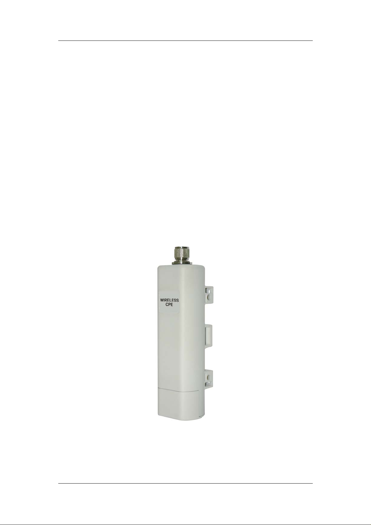
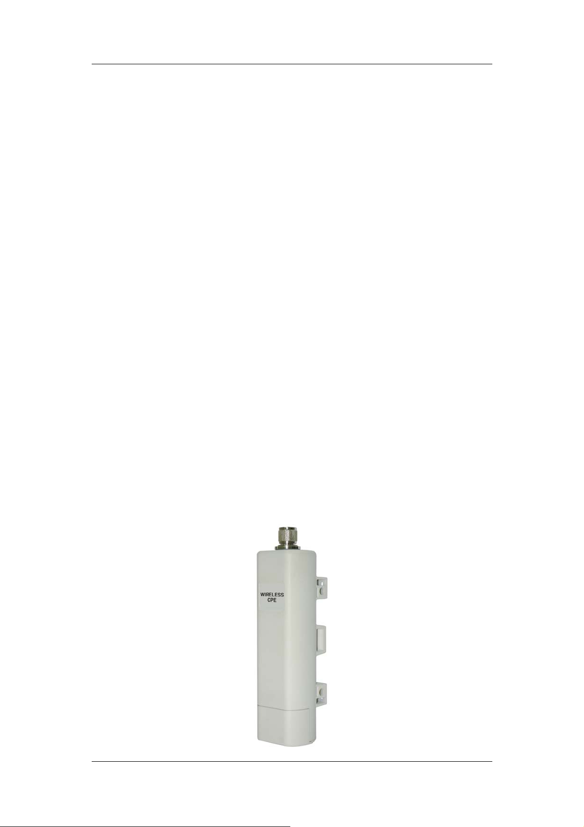
The IEEE802.11n Wireless CPE is a multi-mode last-mile broadband solution for
customers like wireless ISP (WISPs) and system integrators. By the nature of complying with
the IEEE802.11n standard and featuring high power output, IEEE802.1
supports higher bandwidth with lon ger range for outdoor applications.
IEEE802.11n
premises equipment (CPE). While being as the access point, it can be deployed outdoors to
provide outdoor wireless internet service. In the other way to be as the outdoor CPE, it can
receive wireless signal over the last mile, helping WISPs deliver internet service to the new
residential and the business customer where wired broadband internet service, such as cable
and DSL, can not serve in. In addition, the easy-to-install IEEE802.1
covers 2.4GHz bands, which features outstanding throughput performance and a
cost-effective design that allows users to have the reli able outdoor equipment at the affordable
price.
Wireless CPE can be used as the access point or the customer
1n Wireless CPE
1n Wireless CPE
Chapter 1 Introduction Page 5
Page 6

Chapter 2 Preparation before Installation
This chapter describes safety precautions and product information you have to know. Please
check this chapter before installing the IEEE802.1
1n Wireless CPE.
Professional Installation Required
1. Please seek assistance from a professional installer who is well trained in the RF
installation and knowledgeable in the local regulation s.
2. The IEEE802.1
installers with professional technicians and will not be sold directly through retail stores.
1n Wireless CPE is distributed through distributors and system
Safety Precautions
To keep you safe and install the hardware properly, please read and follow these safety
precautions.
1. If you are installing the IEEE802.11
as well as others’, please seek assistance from a professional installer who has
received safety training on the hazards involved.
2. Keep safety as well as performance in mind when selecting your installation site,
especially where there are electric power and phone lines.
3. When installing the IEEE802.11
♦ Do not use a metal ladder;
♦ Do not work on a wet or windy day;
♦ Wear shoes with rubber soles and heels, rubb er gloves, long sleeved shirt or jacket.
4. When the system is operational, avoid standing directly in front of it. Strong RF fields are
present when the transmitter is on.
n Wireless CPE for the first time, for your safety
n Wireless CPE, please note the following things:
Chapter 2 Preparation before Installation Page 6
Page 7

Installation Precautions
To keep the IEEE802.11n Wireless CPE well while you are installing it, please read and
follow these installation precautions.
1. Users MUST use a proper and well-installed surge arrestor and grounding kit with
IEEE802.11n
fatal damage to IEEE802.1
NOT COVERED UNDER WARRNTY.
2. Users MUST use the “Power cord & PoE Injector” shipped in the box with the IEEE802.11n
Wireless CPE. Use of other options will cause damage to the IEEE802.11n Wireless
CPE.
3. Users MUST power off the IEEE802.11n
external antenna to it; otherwise, damage might be caused to the IEEE802.1
CPE itself.
Wireless CPE; otherwise, a random lightening could easily cause
1n Wireless CPE. EMD (Lightning) DAMAGE IS
Wireless CPE first before connecting the
1n Wireless
Product Package
The product package you have received should contain the following items. If any of them are
not included or damaged, please contact your local vendor for support.
IEEE802.11n Wireless CPE ×1
Pole Mounting Ring ×1
Power cord & PoE Injector ×1
Quick Installation Guide ×1
Product CD ×1
Note:
Product CD contains Quick Installation Guide and User Manual!
Chapter 2 Preparation before Installation Page 7
Page 8

- Pole Mounting Ring
- Power cord & PoE Injector
Warning:
Users MUST use the “Power cord & PoE Injector” shipped in the box with the
IEEE802.1
IEEE802.1
1n Wireless CPE. Use of other options will cause damage to the
1n Wireless CPE.
Chapter 2 Preparation before Installation Page 8
Page 9

Chapter 3 System Installation
1. The bottom of the IEEE802.1
aand pull it back harder to take it out as the figure shown below.
2. Plug a standard Ethernet cable into the RJ45 port.
1n Wireless CPE is the movable cover. Grab the cover
3. Slide the cover back to seal the bottom of the IEEE802.11
Chapter 4 Configuration
Page 7
n Wireless CPE.
Page 10

4. T ake out the power cord and PoE injector, and plug the power cord into the DC port of the
PoE injector as the bottom right picture shows.
5. Put what in the Step.3 and Step.4 together by plugging the other side of the Ethernet
cable in the Step.3 into the PoE port of the PoE injector in the Step.4. When you finish the
Step.5, the complete set will be like the following picture.
Chapter 4 Configuration
Page 8
Page 11

6. Turn the IEEE802.11
n Wireless CPE over. Put the pole mounting ring through the
middle hole of the IEEE802.11n Wireless CPE.
Note: Unlock the pole mounting ring by a screw driver before putting it through the
IEEE802.1
1n Wireless CPE as the bottom right picture shows.
Chapter 4 Configuration
Page 11
Page 12

7. Mount the IEEE802.11
n Wireless CPE steadily
to the pole by locking the pole mounting ring tightly.
8. Successful installation.
Chapter 4 Configuration
Page 12
Page 13

Using the external antenna
If you prefer to use the external antenna with N-type connector for your application instead of
the built-in directional antenna, please follow the steps below.
1. Grab the black rubber on the top of the IEEE802.1
it up as the figure shown below. The metal N-type connector will appear.
1n Wireless CPE, and slightly pull
Chapter 4 Configuration
Page 13
Page 14

2. Connect your antenna with the N-type connector on the top of the IEEE802.1
CPE.
Note:
z Before using the external antenna with the N-type connector, users should
prepare the cable in advance, if needed.
z While connecting the N-type connectors, users should pay attention to the
forces they use in prevention of the damage for N-type connectors.
Warning:
z Users MUST power the IEEE802.1
1n Wireless CPE off first before connecting
the external antenna to it; otherwise, damage might be caused to the
1n Wireless
IEEE802.11n Wireless CPE itself.
Chapter 4 Configuration
Page 14
Page 15

Chapter 4 Configuration
Connect the IEEE802.11n Wireless CPE with your PC by an Ethernet cable plugging in LAN
port of PoE injector in one side and in LAN port of PC in the other side. Power on the
IEEE802.1
1. Assign a static IP address to your PC which should be in the same network segm ent with
1n Wireless CPE by PoE from PoE injector.
the IEEE802.1
CPE is 192.168.1.1, you may choose from 192.168.1.2 to 192.168.1.254.
Then click OK.
1n Wireless CPE. As the default IP address of the IEEE802.11n Wireless
2. Open the web browser on your PC, key in the IP address (192.168.1.1) of the
Chapter 4 Configuration
Page 15
Page 16

IEEE802.11n Wireless CPE in the address bar, and then enter.
3. Now, you will see the log-in page of the IEEE802.11
n Wireless CPE. The default
“name” and “password” are “admin” and “password” respectively. Enter them
and then click Login.
* Since the IEEE802.1 1
n Wireless CPE covers “AP mode” as well a s “CPE mode”, the following
steps are categorized for convenience reading to describe how to set each mode after
successful log-in.
AP Mode
1. Choose Wireless > Basic Settings. Then you will see the “Wireless Basic Settings” page.
Chapter 4 Configuration
Page 16
Page 17

The default is AP mode already. Here, you can set the parameters to optimize your
application, or you can leave them as the default. Click Apply to save the parameters.
Note: In the example here, we only change the “Wireless Network Name (SSID)” as
“Join_me”, and later, we will show you if AP mode works correctly. In addition, for better
coverage of the AP, you may also use an external antenna; if so, remember to set the
antenna setting from “Internal (8 dBi)” to “External (N-Type)” after your external antenna is
successfully installed.
2. Choose Security Settings in the left column, and here comes the “Security Settings”
page. You may set the parameters like “Authentication” and “Encryption” for more secure
network communication in your application. Click Apply to save the parameters.
Chapter 4 Configuration
Page 17
Page 18

The following screenshot shows the available access points in the wireless network from
another PC aside. Now, you can see “Join_me” in the list.
Chapter 4 Configuration
Page 18
Page 19

CPE Mode
1. Choose Wireless > Basic Settings. Then you will see the “Wireless Basic Settings”
page. Choose “Wireless Client” from Wireless Mode, and click Apply to save it. Feel free
to change the other parameters to optimize your application before clicking Apply.
Note: For longer transmission of the CPE, you may also use an external antenna; if so,
remember to set the antenna setting from “Internal (8 dBi)” to “External (N-Type)” after
your external antenna is successfully installed.
Chapter 4 Configuration
Page 19
Page 20

2. Click Site Survey, and a “Wireless Site Survey” window will pop up. The window lists all
the available access points / routers in the wireless network. Select the one you prefer to
connect to, and click Selected to build the connection.
Chapter 4 Configuration
Page 20
Page 21

3. If the AP you connect to needs authentication or password, click Security Settings in the
left column, fill out the corresponding items, and click Apply to build the connection;
otherwise, the connection is already built.
Chapter 4 Configuration
Page 21
Page 22

Chapter 5 Troubleshooting
1. Why can’t I go to the log-in page, while I key in 192.168.1.1 in the address bar of the
web browser?
A: Make sure that the IEEE802.11n
powered on already. Then make sure that the IP address of your PC is set in the same
network segment with the IEEE802.11n Wireless CPE, which means that the IP address
of your PC should be between 192.168.1.2 and 192.168.1.255.
2. In the CPE mode, the quality of the connection is bad or unstable af ter choo sing an
available access point to connect to. How can I solve it?
A: Since the IEEE802.11n
you should turn the IEEE802.11n Wireless CPE to face the direction where the access
point you connect to is located to get the best quality of the connection.
In addition, you can also click Site Survey in the “Wireless Basic Settings” window to
see the Signal Strength. If it is weak or unstable (the smaller the number is, the weaker
the signal strength is; please note that the signal strength comes with a native sign with
Wireless CPE comes with the built-in directional antenna,
Wireless CPE is correctly connected with you PC, and
the numbers.), please choose another available access point or router for better
connection.
Chapter 5 Troubleshooting
Page 22
 Loading...