

Page 1
802.11g SOHO
Wir eless Access Point
XG-1020
User’s Manual
Version 1.0 – Novenmber 2006
1
Page 2

Table of Content
Chapter 1 Introduction......................................... ............................. ............................... 3
1-1 Features and Benefits...................................... ..... .. ..... .. ... ..... .. ... .... ... ..... .. .. ..... ... .. ..... 3
1-2 Applications.............................................................................................................. 4
Chapter 2 Hardware Installation..................................................................................... 5
2-1 Package Contents................................................................................... ................... 5
2-2 System Requirements............................................................................................... 5
2-3 Mechanical Description............ ........................................................ ........................ 6
2-4 Hardware Installation ............................................ ................................................... 8
2-5 Safety Notification.......................................... ............................... ........................... 9
Chapter 3 Configuring your Access Point with the Web-Based User Interface ..........10
3-1 Start-up and Log in.............................................. ....................................................10
3-1-1 Status...... ............................. .................................................................................10
3-1-2 System.............................................................. ............................. .......................11
3-2 Wireless Setup.........................................................................................................12
3-2-1 Wireless Settings..................................................................................................12
3-2-1-1 AP Mode ...........................................................................................................12
3-2-1-2 Wireless Client..................................................................................................16
3-2-1-3 Bridge ......................... ............................. ............................. ............................18
3-2-1-4 AP+Repeater.....................................................................................................21
3-2-2 Security Settings...................................................................................................25
3-2-3 MAC Filter................................................ ............................. ..............................28
3-3 Management................................ ............................................................................29
3-3-1 Password Setup ............................................................................. .......................29
3-3-2 Configuration File................................................................................................30
3-3-3 F/W Upload........................... .......................................................... .....................31
3-3-4 Event Log.................................................... ............................. ............................ 32
Limited W arranty............................................................................................................. 2
2
Page 3

Chapter 1 Introduction
The 802.11g SOHO W ireless Access Point is an AP and Bridge Mode, 2.4GHz and up to 54Mbps
wireless LAN access point. The 802.11g SOHO Wireless Access Point can communicate with
other mobile devices enabled for 802.11g standard-based wireless LAN connectivity. Using the
card in conjunction with the 802.11g SOHO Wireless Access Point, you can create a wireless
network for sharing your broadband cable or DSL Internet access among multiple PCs in and
around your home or office and enjoy amazing speed of 54Mbps.
This high-speed wireless device simultaneously supports both IEEE 802.11b and 802.11g
wireless networks and lets you quickly network multiple PCs and notebooks without laying new
cables, and gives users the freedom to roam throughout the workplace and stay connected to
corporate resources, e-mail, and the Internet.
1-1 Features and Benefits
Technique operating in the unlicensed 2.4GHz ISM band.
Support Super-G and Turbo-G: increase the throughput performance.
Interoperable with IEEE 802.11g wireless devices.
Support AP, Wireless Client, Repeater and Bridge Mode.
Enhanced Security: WEP Encryption (64, 128 and 152-bit), 802.1x (EAP-TLS, EAP-TTLS,
LEAP, EAP-PEAP), WPA/ WPA-PSK, WPA2/WPA2-PSK, Wireless MAC MAC Filter List.
Interfaces directly to IEEE 802.3 (10/100-BaseTX RJ-45 LAN port) Fast Ethernet net works.
Supports 1, 2, 5.5, 11, 6, 9, 12, 18, 24, 36, 48, 54 and 108 Mbps (Turbo G / Super G) data
rates.
3
Page 4

1-2 Applications
The 802.11g SOHO Wireless Access Point offers a fast, reliable, high-speed, and high security
solution for wireless clients access to the network in applications like these:
1. Remote access to corporate network information
E-mail, file transfer and terminal emulation.
2. Difficult-to-wire environments
Historical or old buildings, asbestos installations, and open area where wiring is difficult to
deploy.
3. Frequently changing environments
Retailers, manufacturers and those who frequently rearrange the workplace and change
location.
4. Temporary LANs for special projects or peak time
♦ Trade shows, exhibitions and construction sites where a temporary network will be
practical.
♦ Retailers, airline and shipping companies need additional workstations during peak
period.
♦ Auditors requiring workgroups at customer sites.
5. Access to database for mobile workers
Doctors, nurses, retailers, accessing their database while being mobile in the hospital, retail
store or office campus.
6. High security connection
The secure wireless network can be installed quickly and provide flexibility.
4
Page 5

Chapter 2 Hardware Installation
This chapter describes initial setup of the 802.11g SOHO Wireless Access Point.
2-1 Package Contents
The package you have received should contain the following items: If any of the above items are
not included or damaged, please contact your local vendor for support.
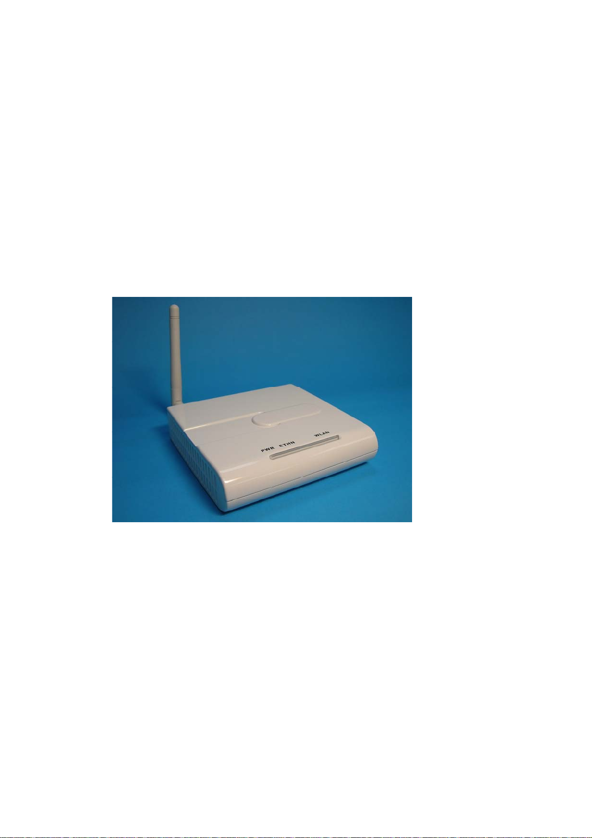
• 802.11g SOHO Wireless Access Point………..…………...…………..………..x1
• Dipole Antenna. ....…………………………………..…………………...……..x1
• Power Adapter…………………………………………………………….……x1
• Product CD….………………………………………………………….………x1
• Quick Installation Guide...………………..…………………………………….x1
2-2 System Requirements
Before installing the 802.11g SOHO Wireless Access Point, please make sure that these
requirements have been met:
A 10/100 Mbps Local Area Network device such as a hub or switch.
Category 5 networking cable.
An A/C power adapter (12V DC).
A Web browser for configuration: Microsoft IE 4.0 or above, or Netscape Navigator 4.5 or
later version.
Installing TCP/IP protocol to the computer.
5
Page 6

2-3 Mechanical Description
Front Panel
The front panel provides LED’s for device status. Refer to the following table for the meaning of
each feature.
LED STATUS Description
Off 802.11g SOHO Wireless Access Point is off.
PWR/SYS
ETHN
EZ Button
On 802.11g SOHO Wireless Access Point is in service.
Green Off No ethernet link is detected.
Green On 10Mbps Ethernet link is detected.
Green
Blinking
Data sending/receiving.
Amber On 100Mbps Ethernet link is detected.
Amber
Blinking
Data sending/receiving.
Off Indicates no 802.11g wireless links.
On Wireless LAN is in service but no activity. WLAN
Blinking Indicates the device is linking or active data through wireless links.
The button to make user easy to setup wireless security.
註解 [NH1]: Front Panel
Picture
6
Page 7

Rear Panel
To know the rear panel features, please refer to the following table for the meaning of each
feature.
註解 [NH2]: Rear Panel Picture
Power
Socket
(DC 12v)
Reset
LAN
ANT.
Connect the DV 12V/1.2A power supply. ONLY use the power adapter
supplied with the 802.11g SOHO Wireless Access Point. Otherwise, the
product may be damaged.
Simply press the reset button and keep pressing it for around 5 seconds.
The 802.11g SOHO Wireless Access Point will be restored to factory
default settings.
Use the Ethernet RJ-45 port to connect to the 10/100Mbps Ethernet
network and Ethernet through a device such as a hub, switch, or router.
This is connector for anntena.
7
Page 8

2-4 Hardware Installation
Before installing the 802.11g SOHO Wireless Access Point, you should make sure that your
Ethernet network is up and working with a computer. You'll be connecting the access p oint to the
Ethernet network so that computers with 802.11g wireless adapters will be able to communicate
with computers on the Ethernet network.
Please take the following steps to successfully to set up the Access Point.
Note: W e suggest you first install the 802.1 1g SO HO W ireless Access Point with default settings.
Site Selection
Before installation, it is very important to decide on the location of the 802.11g SOHO
Wireless Access Point. Proper placement of the 802.11g SOHO Wireless Access Point is
critical to ensure optimum radio range and performance. Typically, the best location t o place
the 802.11g SOHO W ireless Access Point at your site is the center of your wireless coverage
area. Try to place your mobile stations within the line of sight. Obstructions may impede
performance of the 802.11g SOHO Wireless Access Point.
802.11g SOHO Wireless Access Point Pla cement
You can place the 802.11g SOHO Wireless Access Point on a flat surface such as a table or
cabinet, or mount the unit on a vertical surface like a wall. The integrated antenna of your
Access Point performs best in an open environment with as few obstructions as possible. In
most situations placing the 802.11g SOHO Wireless Access Point will provide satisfactory
performance results.
Note: We suggest you configure and verify the 802.11g SOHO Wireless Access Point
operations first before you are planning to mount the 802.11g SOHO Wireless Access Point
on a wall or in a remote location.
Connect the Ethernet Cable
The 802.11g SOHO Wireless Access Point supports 10/100M Ethernet connection. Attach
your UTP Ethernet cable to the RJ-45 connector on the 802.11g SOHO Wireless Access
Point. Then connect the other end of the RJ-45 cable to a hub or a station.
8
Page 9

Connect the Power Cable
Connect the power adapter to the power socket on the 802.11g SOHO W ireless Access Point,
and plug the other end of the power into an electrical outlet.
Warning: We cannot assume the responsibility for the damage from using with the other
power adapter supplier.
Configure the wireless device settings
To access the 802.11g SOHO Wireless Access Point, wireless device needs to configure the
802.11b or 802.11g Wireless Adapter to use the 802.11g SOHO Wireless Access Point
factory default settings as follows:
SSID: Wireless
Channel: 6
WEP: Disable
Verify wireless connectivity to the network
Using a computer with an 802.11b or 802.11g wireless adapter, browse internet or check file
access on the network. If everything is functioning properly, then you have successfully
installed the 802.11g SOHO Wireless Access Point.
2-5 Safety Notification
Your Wireless AP should be placed in a safe and secure location. To ensure proper operation,
please keep the unit away from water and other damaging elements.
Please read the user manual thoroughly before you install the device.
This device should only be repaired by authorized and qualified personnel.
Please do not try to open or repair the device yourself.
Do not place the device in a damp or humid location, i.e. a bathroom.
Please do not expose the device to direct sunlight or other heat sources. The housing and
electronic components may be damaged by direct sunlight or heat sources.
9
Page 10
Chapter 3 Configuring your Access Point
with the Web-Based User Interface
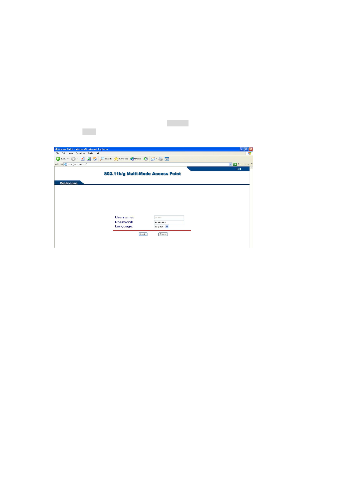
3-1 Start-up and Log in
In order to configure the Access Point, you must use your web browser and please do the
following:
1. Type this Access Point’s address http://192.168.1.1
and press Enter.
2. Enter the system password (the default setting is “password”).
3. Click on the “Login” button.
4. The main page will appear.
in the Location (for IE) or Address field
After you have logged-in the main page, the Status, System, Wireless Setup, AP Status,
Management buttons will be shown. The main menu provides links to the whole sections of the
web configuration interface.
3-1-1 Status
The Status screen describes the product information briefly. The device status includes Access
Point Information, IP settings, and Wireless settings.
10
Page 11
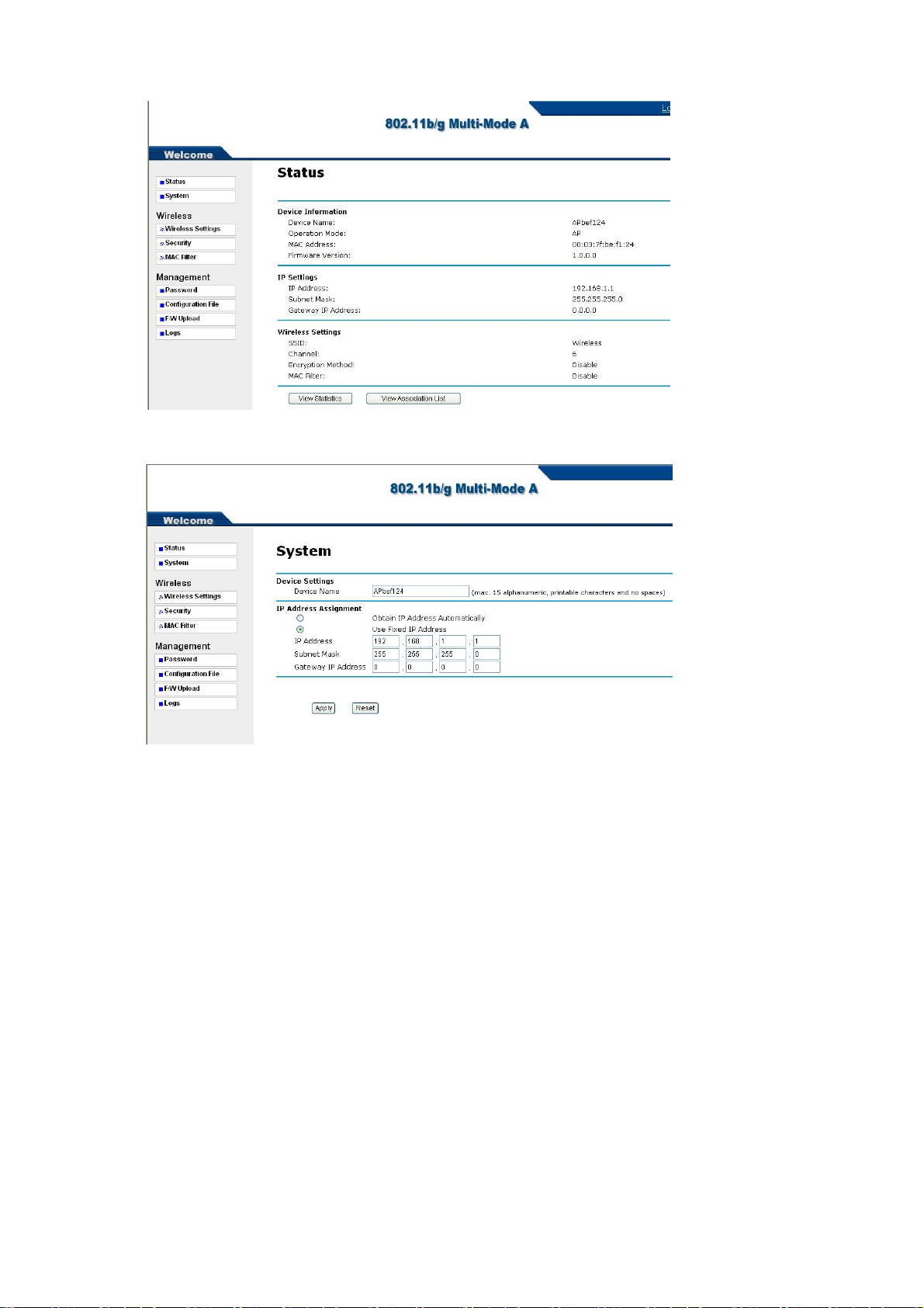
3-1-2 System
The Device Name is used to give a name to your Access Point. This will enable you to manage
your Access Point more easily if you have multiple Access Points on your network.
IP Address Assigment: Allow you to setup your device ip address. You can use fixed IP address
or obtain IP address automatically.
Note: If you complete the settings, please click on “Apply” for changes to take effect.
11
Page 12
3-2 Wireless Setup
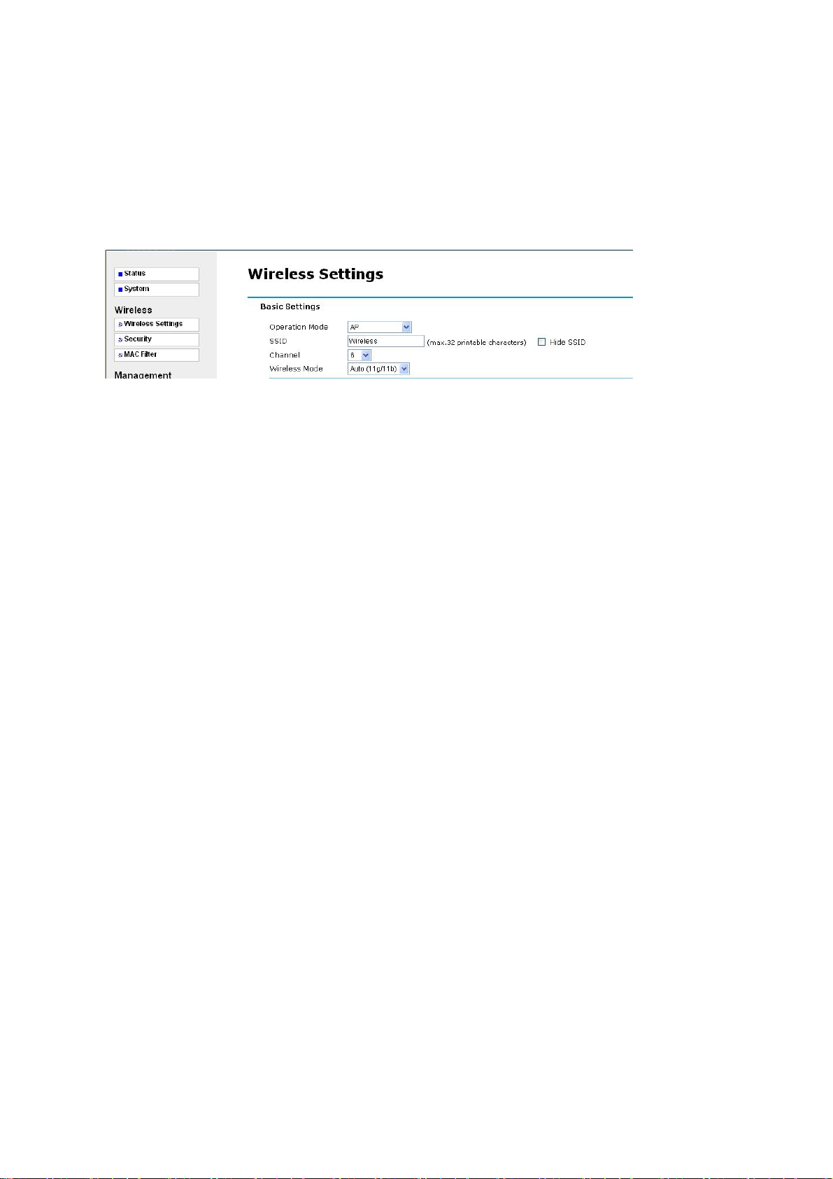
3-2-1 Wireless Settings
The Wireless LAN Setup page lets you m ake changes to the w ireless network settings. The Basic
Settings, you can make changes to the wireless network name Operation Mode, SSID,
Broadcast SSID, Wi reless M ode, Channel/Frequency. The Advance Settings, you can make
changes to the other advance settings, such as Output Power, Data Rate etc.
Basic Settings
Operation Mode: Selecte the operating mode from the drop-down list. The options are Access
Point, Wireless Client, Bridge, AP+Repeater.
3-2-1-1 AP Mode
SSID: The SSID is a unique ID used by Access Points and Stations to identify a wireless LAN.
Wireless clients associating to any Access Point must have the same SSID. The default SSID is
“Wireless”. To change the SSID, type in the SSID you like to use. It is case sensitive and must not
exceed 32 characters.
Hide SSID: For security concern, you can choose not to broadcast your network’s SSID. To turn
off the broadcast of the SSID, click “No” check box next to “Broadcast SSID”. And your Access
Point will refuse the connection requests from whose are not a ware the Network ID. But certainly
the Access Point can be easily connected well when you realize the Network ID. The default
setting is “Yes”.
12
Page 13

Wireless Mode: There are three different wireless modes to op erate, “Auto (11g/11b)”, “802.11b
only”, and “802.11g only”. In Auto (11g/11b) mode, the access point is compatible with a mix of
both 802.11g and 802.11b clients. You will see that the factory-set default “Auto (11b/11g)” will
prove the most efficient. 802.11b only mode is compatible with 802.11b clients only. This mode
can be used only if you do not allow any 802.11g clients to access to the network. 802.11g only
mode is compatible with 802.11g clients only. This mode can be used only if you do not allow any
802.11b clients to access to the network. To switch the mode, select the desired mode form the
pull-down menu next to “Wireless Mode”.
Channel: Select the appropriate channel from the list provided to correspond with your network
settings.
Advance settings
Beacon Interval: This value indicates the frequency interval of the beacon. A beacon is a packet
broadcast by the Access Point to keep the network synchronized. A beacon includes the wireless
LAN service area, the AP address, the Broadcast destination addresses, a time stamp, Delivery
Traffic Indicator Maps, and the Traffic Indicator Message (TIM).
Intra-BSS traffic: Intra-BSS traffic is trffic between wireless stations in the same BSS.
Enable Intra-BSS traffic to allow wireless stations connected to the device to communicate with
each other.
Disable Intra-BSS traffic to only allow wireless stations to communicate with wired network, not
with each other.
13
Page 14

DTIM Interval: This value indicates the interval of the Delivery Traffic Indication Message
(DTIM). A DTIM field is a countdown field informing clients of the next window for listening to
broadcast and multicast messages. When the Access Point has buffered broadcast or multicast
messages for associated clients, it sends the next DTIM with a DTIM Interval value. Clients can
hear the beacons and awaken to receive the broadcast and multicast messages.
WMM: WMM (Wi-Fi Multi-media) function is to promote wireless Qulity of Service
technology. Enable WMM for Wi-Fi WMM cetificate test.
Number of Wireless Stations Allowed to Associate: Use this field to set a maximum number of
wireless stations that may connect to the device.
Enter the number (1 to 32) of wireless stations allowed.
Radio Enable: Turn on the wireless adapter to allow wireless communications between the
device and other IEEE802.11b and IEEE802.11g compliant wireless device. Turn off the wireless
adapter to stop wireless communications between the device and other IEEE802.11b and
IEEE802.11g compliant wireless device.
Output Power Management:
half, quarter, eighth and min. Decrease the trans mit power if ne cessary. The default is “full”.
Set the transmit signal st rength of the access point. The o ptions are full,
Date Rate Management: The basic transfer rates should be set depending on the speed of your
wireless network. Specifies rate of data transmission. Select the desired rate from the drop-down
menu and choose “Best” to adapt the rate to the best available.
Preamble Type: The Preamble defines the length of the PLCP synchronization field for
communication between the Access Point and Network Card. Select the appropriate preamble
type and press the Apply button to set it. The default setting is ‘Dynamic’.
Super-G Mode: Enable Super-G may enhance the wireless throughput. The default setting is
Disable.
Turbo-G Mode: Enable Turbo-G may enhance the wireless throughput. The default setting is
Disable.
RTS/CTS Threshold: RTS Threshold is a mechanism implemented to prevent the “Hidden
Node” problem. If the size of the packet transmitted is larger than the value you set, the RTS will
be enabled. When the RTS is activated, the station and its Access Point will use a (RTS/CTS)
mechanism for data transmission. The setting range is 0-2346.
Fragmentation: Fragmentation mechanism is used for improving the efficiency when there is
high traffic within the wireless network. If you transmit lar ge files in a wireless network, you can
enable the Fragmentation Threshold and specify the packet size. This specifies the maximum size
a data packet will be before splitting and creating a new packet. The setting range is 256-2346.
For example: If you set value as 256, it means the packet will be fragmented into “256” bytes
14
Page 15

while transmitting.
Note: If you complete the settings, please click on “Apply” for changes to take effect.
15
Page 16

3-2-1-2 Wireless Client
Select Wireless Client in the Operation Mode field to display the screen as shown next. This
mode has the device act as wireless client to connect to a wireless network.
Note: WPA, WPA2 and IEEE 802.1x wireless security are not available when you use Wireless
Client, Bridge or AP+Repeater mode.
Basic Settings
Operation Mode: Selecte the operating mode from the drop-down list. The options are Access
Point, Wireless Client, Bridge, AP+Repeater.
SSID: The SSID is a unique ID used by Access Points and Stations to identify a wireless LAN.
Wireless clients associating to any Access Point must have the same SSID. The default SSID is
“Wireless”. To change the SSID, type in the SSID you like to use. It is case sensitive and must not
exceed 32 characters.
Wireless Mode: There are three different wireless modes to op erate, “Auto (11g/11b)”, “802.11b
only”, and “802.11g only”. In Auto (11g/11b) mode, the access point is compatible with a mix of
both 802.11g and 802.11b clients. You will see that the factory-set default “Auto (11b/11g)” will
prove the most efficient. 802.11b only mode is compatible with 802.11b clients only. This mode
can be used only if you do not allow any 802.11g clients to access to the network. 802.11g only
mode is compatible with 802.11g clients only. This mode can be used only if you do not allow any
802.11b clients to access to the network. To switch the mode, select the desired mode form the
pull-down menu next to “Wireless Mode”.
Site Survey: Press Site Survey to find the active Access Point.
Advance Settings
16
Page 17

Radio Enable: Turn on the wireless adapter to allow wireless communications between the
device and other IEEE802.11b and IEEE802.11g compliant wireless device. Turn off the wireless
adapter to stop wireless communications between the device and other IEEE802.11b and
IEEE802.11g compliant wireless device.
Output Power Management:
half, quarter, eighth and min. Decrease the trans mit power if ne cessary. The default is “full”.
Set the transmit signal st rength of the access point. The o ptions are full,
Date Rate Management: The basic transfer rates should be set depending on the speed of your
wireless network. Specifies rate of data transmission. Select the desired rate from the drop-down
menu and choose “Best” to adapt the rate to the best available.
Preamble Type: The Preamble defines the length of the PLCP synchronization field for
communication between the Access Point and Network Card. Select the appropriate preamble
type and press the Apply button to set it. The default setting is ‘Dynamic’.
Super-G Mode: Enable Super-G may enhance the wireless throughput. The default setting is
Disable.
RTS/CTS Threshold: RTS Threshold is a mechanism implemented to prevent the “Hidden
Node” problem. If the size of the packet transmitted is larger than the value you set, the RTS will
be enabled. When the RTS is activated, the station and its Access Point will use a (RTS/CTS)
mechanism for data transmission. The setting range is 0-2346.
Fragmentation: Fragmentation mechanism is used for improving the efficiency when there is
high traffic within the wireless network. If you transmit lar ge files in a wireless network, you can
enable the Fragmentation Threshold and specify the packet size. This specifies the maximum size
a data packet will be before splitting and creating a new packet. The setting range is 256-2346.
For example: If you set value as 256, it means the packet will be fragmented into “256” bytes
while transmitting.
Note: If you complete the settings, please click on “Apply” for changes to take effect.
17
Page 18

3-2-1-3 Bridge
The device can act as a wireless network bridge and establish wireless links with other APs. You
need to know the MAC address of the peer device, which also must be in bridge mode.
When twi devices connect in Bridge mode, they form a WDS (Wireless Distribution System)
allowing the computers in one LAN to connect to the computers in another LAN. See the
following example.
Note: WP A, WPA2 and IEEE 802.1x wireless security are not available w hen you use Wireless
Client, Bridge or AP+Repeater mode.
Bridging example
Select Bridge as the Operation Mode to let the device act as a wireless bridge only.
18
Page 19

Basic Settings
Operation Mode: Selecte the operating mode from the drop-down list. The options are Access
Point, Wireless Client, Bridge, AP+Repeater.
Channel: Select the appropriate channel from the list provided to correspond with your network
settings.
Wireless Mode: There are three different wireless modes to op erate, “Auto (11g/11b)”, “802.11b
only”, and “802.11g only”. In Auto (11g/11b) mode, the access point is compatible with a mix of
both 802.11g and 802.11b clients. You will see that the factory-set default “Auto (11b/11g)” will
prove the most efficient. 802.11b only mode is compatible with 802.11b clients only. This mode
can be used only if you do not allow any 802.11g clients to access to the network. 802.11g only
mode is compatible with 802.11g clients only. This mode can be used only if you do not allow any
802.11b clients to access to the network. To switch the mode, select the desired mode form the
pull-down menu next to “Wireless Mode”.
Local MAC Address: This is the MAC address of the device.
Romote MAC Address 1-4: Type the MAC address of the peer device in a valid MAC address
format, that is six hexadecimal character pairs.
Advance Settings
Radio Enable: Turn on the wireless adapter to allow wireless communications between the
device and other IEEE802.11b and IEEE802.11g compliant wireless device. Turn off the wireless
adapter to stop wireless communications between the device and other IEEE802.11b and
IEEE802.11g compliant wireless device.
Output Power Management:
half, quarter, eighth and min. Decrease the trans mit power if ne cessary. The default is “full”.
Set the transmit signal st rength of the access point. The o ptions are full,
Date Rate Management: The basic transfer rates should be set depending on the speed of your
19
Page 20

wireless network. Specifies rate of data transmission. Select the desired rate from the drop-down
menu and choose “Best” to adapt the rate to the best available.
Preamble Type: The Preamble defines the length of the PLCP synchronization field for
communication between the Access Point and Network Card. Select the appropriate preamble
type and press the Apply button to set it. The default setting is ‘Dynamic’.
Super-G Mode: Enable Super-G may enhance the wireless throughput. The default setting is
Disable.
RTS/CTS Threshold: RTS Threshold is a mechanism implemented to prevent the “Hidden
Node” problem. If the size of the packet transmitted is larger than the value you set, the RTS will
be enabled. When the RTS is activated, the station and its Access Point will use a (RTS/CTS)
mechanism for data transmission. The setting range is 0-2346.
Fragmentation: Fragmentation mechanism is used for improving the efficiency when there is
high traffic within the wireless network. If you transmit lar ge files in a wireless network, you can
enable the Fragmentation Threshold and specify the packet size. This specifies the maximum size
a data packet will be before splitting and creating a new packet. The setting range is 256-2346.
For example: If you set value as 256, it means the packet will be fragmented into “256” bytes
while transmitting.
Note: If you complete the settings, please click on “Apply” for changes to take effect.
20
Page 21

3-2-1-4 AP+Repeater
Select AP+Repeater as the Operation Mode to have the device act as an access point and a
wireless bridge.
Basic Settings
Operation Mode: Selecte the operating mode from the drop-down list. The options are Access
Point, Wireless Client, Bridge, AP+Repeater.
SSID: The SSID is a unique ID used by Access Points and Stations to identify a wireless LAN.
Wireless clients associating to any Access Point must have the same SSID. The default SSID is
“Wireless”. To change the SSID, type in the SSID you like to use. It is case sensitive and must not
exceed 32 characters.
Hide SSID: For security concern, you can choose not to broadcast your network’s SSID. To turn
21
Page 22

off the broadcast of the SSID, click “No” check box next to “Broadcast SSID”. And your Access
Point will refuse the connection requests from whose are not a ware the Network ID. But certainly
the Access Point can be easily connected well when you realize the Network ID. The default
setting is “Yes”.
Wireless Mode: There are three different wireless modes to op erate, “Auto (11g/11b)”, “802.11b
only”, and “802.11g only”. In Auto (11g/11b) mode, the access point is compatible with a mix of
both 802.11g and 802.11b clients. You will see that the factory-set default “Auto (11b/11g)” will
prove the most efficient. 802.11b only mode is compatible with 802.11b clients only. This mode
can be used only if you do not allow any 802.11g clients to access to the network. 802.11g only
mode is compatible with 802.11g clients only. This mode can be used only if you do not allow any
802.11b clients to access to the network. To switch the mode, select the desired mode form the
pull-down menu next to “Wireless Mode”.
Channel: Select the appropriate channel from the list provided to correspond with your network
settings.
WDS Settings
Local MAC Address: This is MAC address of the device.
Romote MAC Address 1-4: Type the MAC address of the peer device in a valid MAC address
format, that is six hexadecimal character pairs.
Advance settings
Beacon Interval: This value indicates the frequency interval of the beacon. A beacon is a packet
broadcast by the Access Point to keep the network synchronized. A beacon includes the wireless
LAN service area, the AP address, the Broadcast destination addresses, a time stamp, Delivery
22
Page 23

Traffic Indicator Maps, and the Traffic Indicator Message (TIM).
Intra-BSS traffic: Intra-BSS traffic is trffic between wireless stations in the same BSS.
Enable Intra-BSS traffic to allow wireless stations connected to the device to communicate with
each other.
Disable Intra-BSS traffic to only allow wireless stations to communicate with wired network, not
with each other.
DTIM Interval: This value indicates the interval of the Delivery Traffic Indication Message
(DTIM). A DTIM field is a countdown field informing clients of the next window for listening to
broadcast and multicast messages. When the Access Point has buffered broadcast or multicast
messages for associated clients, it sends the next DTIM with a DTIM Interval value. Clients can
hear the beacons and awaken to receive the broadcast and multicast messages.
WMM: WMM (Wi-Fi Multi-media) function is to promote wireless Qulity of Service
technology. Enable WMM for Wi-Fi WMM cetificate test.
Number of Wireless Stations Allowed to Associate: Use this field to set a maximum number of
wireless stations that may connect to the device.
Enter the number (1 to 32) of wireless stations allowed.
Radio Enable: Turn on the wireless adapter to allow wireless communications between the
device and other IEEE802.11b and IEEE802.11g compliant wireless device. Turn off the wireless
adapter to stop wireless communications between the device and other IEEE802.11b and
IEEE802.11g compliant wireless device.
Output Power Management:
half, quarter, eighth and min. Decrease the trans mit power if ne cessary. The default is “full”.
Set the transmit signal st rength of the access point. The o ptions are full,
Date Rate Management: The basic transfer rates should be set depending on the speed of your
wireless network. Specifies rate of data transmission. Select the desired rate from the drop-down
menu and choose “Best” to adapt the rate to the best available.
Preamble Type: The Preamble defines the length of the PLCP synchronization field for
communication between the Access Point and Network Card. Select the appropriate preamble
type and press the Apply button to set it. The default setting is ‘Dynamic’.
Super-G Mode: Enable Super-G may enhance the wireless throughput. The default setting is
Disable.
Turbo-G Mode: Enable Turbo-G may enhance the wireless throughput. The default setting is
Disable.
RTS/CTS Threshold: RTS Threshold is a mechanism implemented to prevent the “Hidden
23
Page 24

Node” problem. If the size of the packet transmitted is larger than the value you set, the RTS will
be enabled. When the RTS is activated, the station and its Access Point will use a (RTS/CTS)
mechanism for data transmission. The setting range is 0-2346.
Fragmentation: Fragmentation mechanism is used for improving the efficiency when there is
high traffic within the wireless network. If you transmit lar ge files in a wireless network, you can
enable the Fragmentation Threshold and specify the packet size. This specifies the maximum size
a data packet will be before splitting and creating a new packet. The setting range is 256-2346.
For example: If you set value as 256, it means the packet will be fragmented into “256” bytes
while transmitting.
Note: If you complete the settings, please click on “Apply” for changes to take effect.
24
Page 25

3-2-2 Security Settings
WEP
To prevent unauthorized wireless stations from accessing data transmitted over the network, the
Access Point Security Settings window offers WEP features, making your data transmission over
air more secure and allows you to specify Encryption Key(s) if you enable encryption for the
Access Point.
Network Authentication
Choose the Network Authentication Type.
Open System: Requires NO authentication, since it allows any device to join a network without
performing any security check. The Authentication Type default is set to “Open System”. We
recommend that you use the default setting.
Shared Key: Requires that the station and the access point use t he same WEP key to authenticate.
This basically means that WEP must be enabled and configured on both the access point and the
client with a same key. All points on your network must use the same authentication type.
Legacy 802.1x: If selected, you must configure the Radius Server Setting Screen.
WPA: If selected, you must configure the Radius Server Setting Screen.
Note: When Operation Mode is setted in Wireless Client or Bridge mode, WPA can’t be
setted.
25
Page 26

WPA2: If selected, you must configure the Radius Server Setting Screen.
Note: When Operation Mode is setted in Wireless Client or Bridge mode, WPA2 can’t
be setted.
WPA&WPA2: If selected, you must configure the Radius Server Setting Screen.
Note: When Operation Mode is setted in Wireless Client or Bridge mode,
WPA&WPA2 can’t be setted.
WPA-PSK: If selected, you must use TKIP encryption, and enter the WPA Pre-Shared Key.
WPA Pre-Shared Key: In the WAP-PSK field, you may enter 8-63 characters ranging from
“a-z”, “A-Z”, and “0-9”.
WPA2-PSK: If selected, you must use AES encryption, and enter the WPA2 Pre-Shared Key.
WPA2 Pre-Shared Key: In the WAP2-PSK field, you may enter 8-63 characters ranging from
“a-z”, “A-Z”, and “0-9”.
WPA-PSK & WPA2-PSK: If selected, you must use AES encryption, and enter the WPA2
Pre-Shared Key.
WPA & WPA2 Pre-Shared Key: In the WAP2-PSK field, you may enter 8-63 characters
ranging from “a-z”, “A-Z”, and “0-9”.
Data Encryption:
Select the desired potion. If enabled (64 bit WEP, 128 bit WEP, 152 bit WEP), the keys must have
the same encryption strength and must be the same with the keys that other wireless stations use.
The TKIP option is automatically activated when either “WPA”, or “WPA-PSK” is enabled. The
AES option is automatically activated either “WPA2”, or “WPS2-PSK” is enabled.
WEP Passphrase:
There are two methods for creating WEP data encryption:
z Using a Passphrase: Type in a passphrase and click “Generate Keys”. Passphrase can be a
mixture of numbers and letters. When entering passphrase, you must not exceed 32
characters. As you type, the wireless access point will use an algorithm to generate 4 keys
automatically. Select one key from the 4 WEP keys.
z Manually:
64 bits WEP: Enter 5 ASCII characters or 10 hexadecimal digits (between 0-9, a-f and
A-F).
128 bits WEP: Enter 13 ASCII characters or 26 hexadecimal digits (between 0-9, a-f and
A-F).
152 bits WEP: Enter 16 ASCII characters or 32 hexadecimal digits (between 0-9, a-f and
26
Page 27

A-F).
Note: The WEP key must be set up exactly the sam e on the Wireless Ac cess Points as they are on
the wireless clients. If you set “0011223344” for the Wireless Access Point, the same WEP key
“0011223344” must be assigned to other client stations.
Authentication Server
Authentication Server IP Address: Enter the IP address of the external authentication server
in dotted decimal notation.
Port number: Enter the port number of the external authentication server. The default port
number is 1812.
You need not change this value unless your network administrator instructs you to do so with
additional information.
Shared Secret: Enter a password (up to 63 printable charaters) as the key to be shared between
the external authentication server and the device.
The key must be the same on the external authentication server and your device.The key is not
sent over the network.
Rekey Options
Reauthentication Time: Specify how often wireless stations have to resend user names and
passwords in order to stay connected. Enter a time interval between 100 and 3600 seconds. If
wireless station authentication is done using a RADIUS server, the reauthentication timer on the
RADIUS server has priority.
Global-key Update: This is how often the AP sends a new group key out to all clients. The
re-keying process is the WPA equivalent of automatically changing the WEP key for an AP and
all stations in a WLAN on a periodic basis.
Specify an interval either in seconds or thousands of packets that the device sends.
Note: If you complete the settings, please click on “Apply” for changes to take effect.
27
Page 28

3-2-3 MAC Filter
The MAC Filter allows you to restrict wireless access by MAC Address. This provides an
additional layer of security. To change your device’s MAC filter settings, click MAC Filter, and
select the check box of Active.
Note: Be careful not to list your computer’s MAC address and select Deny the following MAC
address to associate when managing the device via a wireless connection. This would lock you
out.
28
Page 29

3-3 Management
3-3-1 Password Setup
Here allow you to change the Access Point’s password, do the following:
1. To change the current password, choose the “Change Password” option from the
“Management” section in the Wireless Access Point’s left page. Key in the default password
“password” in the “Current Password” filed.
2. Changing password for the Access Point is as easy as typing the password into the New
Password field. Then, type it again into the Retype New Field to confirm. Click the “Apply”
button to save the setting.
Note: After you change password, please take note of your new password. Otherwise, you will
not able to access the Wireless Access Point setup. If you forget the password, you could restore
the default password “password” by clicking the “Yes” check box in the “Restore Default
Password” field or pressing the Reset button on the back panel of your Wireless Access Point for
at least 10 second – and all previous configurations will need to be input again.
29
Page 30

3-3-2 Configuration File
Backup Configuration: Allow to backup your current configuration to your computer.
Restore Configuration: To restore your configuration from a previously saved configuration
file.
Back to Factory Defaults: The reset button will clear all user-entered configurations and will
reset the device settings back to its factory default value.
-Password: password
-Lan IP address: 192.168.1.1
30
Page 31

3-3-3 F/W Upload
The Upgrade Firmware menu will display the Upgrade Firmware window so that you could
update the latest firmware on the 802.11g SOHO Wireless Access Point.
Please make sure that you have downloaded the latest and correct firmware from the product
support website and store it in local drive before upgrading the firmware of the 802.11g SOHO
Wireless Access Point.
To upgrade the latest firmware, complete the following:
z Using brows e r to access (192.168.1.1) AP’s main page.
1. Select F/W Upload from the Management section.
2. Input the exact file path and name by clicking Browse button, then press Upload button to
upgrade the firmware.
3. Please wait for 150 seconds.
z If download fail, please rep eat the step 1~3 to download again.
z Note! Do not power off the unit when it is being upgraded.
31
Page 32

3-3-4 Logs
You can view logs and alert messages in the screen. Once the log table is full, old logs are
deleted as new logs are created.
Refresh: Click Refresh to renew the log screen.
Clear Log: Click Clear Log to clear all the logs.
32
Page 33

注意 !
依據 低功率電波輻射性電機管理辦法
第十二條 經型式認證合格之低功率射頻電機,非經許可,公司、商號或使用
者均不得擅自變更頻率、加大功率或變更原設計之特性及功能。
第十四條 低功率射頻電機之使用不得影響飛航安全及干擾合法通信;經發現
有干擾現象時,應立即停用,並改善至無干擾時方得繼續使用。
前項合法通信,指依電信規定作業之無線電信。低功率射頻電機須忍
受合法通信或工業、科學及醫療用電波輻射性電機設備之干擾。
1
Page 34

Caution
This device, complies with Part 15 of the FCC Rules. Operation is subject to the following two conditions:
(1) this device may not cause harmful interference, and (2) this device must accept any interference
received; including interference that may cause undesired operation.
This Transmitter must not be co-located or operating in conjunction with any other antenna or transmitter.
This antenna(s) used for this transmitter must be installed to provide a separation distance of at least 20
cm from all persons and must not be co-located or operation in conjunction with any other antenna or
transmitter.
Federal Communications Commission (FCC) Statement
This Equipment has been tested and found to comply with the limits for a Class B digital device, pursuant
to Part 15 of the FCC rules. These limits are designed to provide reasonable protection against harmful
interference in a residential installation. This equipment generates uses and can radiate radio frequency
energy and, if not installed and used in accordance with the instructions, may cause harmful interference to
radio communications. However, there is no guarantee that interference will not occur in a particular
installation. If this equipment does cause harmful interference to radio or television reception, which can be
determined by turning the equipment off and on, the user is encouraged to try to correct the interference by
one or more of the following measures:
- Reorient or relocate the receiving antenna.
- Increase the separation between the equipment and receiver.
- Connect the equipment into an outlet on a circuit different from that to which the receiver is
connected.
- Consult the dealer or an experienced radio/TV technician for help.
Warning: Any changes or modifications to this unit not expressly approved by the party responsible for
compliance could void the user authority to operate the equipment.
1
Page 35

Limited Warranty
This W arranty constit utes the sole and exclusive r emedy of any buyer or reseller’ s equipment and
the sole and exclusive liability of the supplier in connection with the products and is in lieu of all
other warranties, express, implied or statutory , including, but n ot limited to, any implied warranty
of merchantability of fitness for a particular use and all other obligations or liabilities of the
supplier.
In no even will the supplier or any other party or person be liable to your or anyone else for any
damages, including lost profits, lost savings or other incidental or consequential damages, or
inability to use the software provided on the software media even if the supplier or the other party
person has been advised of the possibility of such damages.
The following are special terms applicable to your hardware warranty as well as services you may
use during part of the warranty period. Your formal Warranty Statement, including the warranty
applicable to our Wireless LAN products, appears in the Quick Installation Guide that
accompanies your products.
Duration of Hardware Warranty: 13 months
Replacement, Repair or Refund Procedure for Hardware:
If your unit needs a repair or replacement, return it to your dealer/distributor in its original
packaging. When returning a defective product for Warranty, always include the following
documents:
The W arrant y Repair Card
A copy of the invoice/proof of purchase, and
The RMA Report Form (To receive a Return Materials Authorization form (RMA), please
contact the party from whom you purchased the product).
Upon proof-of-purchase we shall, at its option, repair or replace the defective item at no cost to
the buyer.
This warranty is contingent upon proper use in the application for which the products are intended
and does not cover products which have been modified without the reseller’s approval or which
have been subjected to unusual physical or electrical demands or damaged in any way.
2
Page 36

Please complete the information below and include it along with your products.
Name:
Title:
Company:
Telephone:
Fax:
Email:
City/State/Zip code:
Country:
Product Name:
Serial Number:
MAC Address:
Invoice Date:
Product Description:
If you have any further questions, please contact your local authorized reseller for support.
3
Page 37

Z-Com, Inc.
A W ir eless Networking Company
Product Specification
XG-1020 Wireless AP/Bridge
STANDARD
IEEE 802.1 1b standard compliant
IEEE 802.1 1g standard compliant
RADIO
Chipset Atheros
Antenna 1 * undetachable dipole antenna
7F-2, No.9, Prosperity 1st Rd.,
Science-Based Industrial Park,
Hsinchu, 300 Taiwan
Tel
: 886-3-5777364
Fax
: 886-3-5773359
Frequency
Modulation
Output Power (w/
Ant. Gain)
HARDWARE SPECIFICAIONS
。 One 10/100Base-T Ethernet, full-duplex with auto MDI/MDIX support
。 Power Supply: 12V DC, 1A
。 Reset Button (reset to default)
。 EZ Config. Button: WPS support *
USA (FCC) 1 1 Channels: 2.412GHz~2.462GHz
Europe (ETSI) 13 Channels : 2.412GHz~2.472GHz
Japan (ARIB) 13 Channels : 2.412GHz~2.472GHz
1 1g Orthogonal Frequency Division Multiplexing (OFDM)
(64QAM, 16QAM, QPSK, BPSK)
1 1b Direct Sequence Spread S pectrum (DSSS)
(CCK, DQPSK, DBPSK)
1 1g Radio 54Mbps 22.58dBm (Max.)
1 1b Radio 1 1Mbps 18.52 dBm (Max.)
1 1g Mode: 54, 48, 36, 24, 18, 12, 9, 6 Mbps Data Rate
1 1b Mode: 11, 5.5, 2, 1 Mbps
* Note: WPS support will be released by end of ’06.
SOFTWARE FEATURES
。 Operation Modes: AP, Repeater, Bridge & Wireless Client
。 “Wireless Super G” technology support
。 Security protection with WPA/ WPA2, 802.1x & WEP 512-bit
。 WPS support (*)
* Note: WPS support will be released by end of Q2’07.
Page 38

7F-2, No.9, Prosperity 1st Rd.,
Science-Based Industrial Park,
Z-Com, Inc.
A W ir eless Networking Company
MEMORY SIZE
Flash 4MB (Serial Flash)
SDRAM 16MB
PHYSICAL SPECIFICATIONS
Dimension 110mm(L)*125mm(W)*30mm(H)
Weight 200g (approx.)
ENVIRONMENTAL SPECIFICATIONS
Temperature (Ambient) Humidity (non-condensing)
Hsinchu, 300 Taiwan
: 886-3-5777364
Tel
: 886-3-5773359
Fax
Operating
Storage
SYSTEM REQUIREMENT
。 Broadband (cable, DSL, satellite or wireless) Internet service & modem with
Ethernet RJ-45 connector
。 Ethernet connection (adapter or cable)
。 Windows operation system
。 Internet Explorer 5.0 or above
WARRANTY
12 months
0~50℃
-10~65℃
90%
5~95%
 Loading...