

Page 1

Z-Com NPort WS-120
Manual
V3.0
M User's
2007-4-11 First Release author:Aaron
2007-5-26 Function Add author:Aaron
Page1
Page 2

Federal Communication Commission Interference Statement
This equipment has been tested and found to comply with the limits for a Class B digital device,
pursuant to Part 15 of the FCC Rules. These limits are designed to provide reasonable protection
against harmful interference in a residential installation. This equipment generates, uses and can
radiate radio frequency energy and, if not installed and used in accordance with the instructions,
may cause harmful interference to radio communications. However, there is no guarantee that
interference will not occur in a particular installation. If this equipment does cause harmful
interference to radio or television reception, which can be determined by turning the equipment off
and on, the user is encouraged to try to correct the interference by one of the following measures:
● Reorient or relocate the receiving antenna.
● Increase the separation between the equipment and receiver.
● Connect the equipment into an outlet on a circuit different from that to which the receiver is
connected.
● Consult the dealer or an experienced radio/TV technician for help.
FCC Caution: Any changes or modifications not expressly approved by the party responsible for
compliance could void the user’s authority to operate this equipment.
This device complies with Part 15 of the FCC Rules. Operation is subject to the following two
conditions: (1) This device may not cause harmful interference, and (2) this device must accept any
interference received, including interference that may cause undesired operation.
For product available in the USA market, only channel 1~11 can be operated. Selection of other
channels is not possible.
This device and its antenna(s) must not be co-located or operation in conjunction with any other
antenna or transmitter.
IMPORTANT NOTE:
This module is intended for OEM integrator. The OEM integrator is still responsible for the FCC
compliance requirement of the end product, which integrates this module.
20cm minimum distance has to be able to be maintained between the antenna and the users for the
host this module is integrated into. Under such configuration, the FCC radiation exposure limits set
forth for an population/uncontrolled environment can be satisfied.
Any changes or modifications not expressly approved by the manufacturer could void the user's
authority to operate this equipment.
USERS MANUAL OF THE END PRODUCT:
In the users manual of the end product, the end user has to be informed to keep at least 20cm
separation with the antenna while this end product is installed and operated. The end user h as to be
informed that the FCC radio-frequency exposure guidelines for an uncontrolled environment can be
satisfied. The end user has to also be informed that any changes or modifications not expressly
approved by the manufacturer could void the user's authority to operate this equipment. If the size of
the end product is smaller than 8x10cm, then additional FCC part 15.19 statement is required to be
available in the users manual: This device complies with Part 15 of FCC rules. Operation is subject
to the following two conditions: (1) this device may not cause harmful interference and (2) this d evice
must accept any interference received, including interference that may cause undesired operation.
LABEL OF THE END PRODUCT:
The final end product must be labeled in a visible area with the following " Contains TX FCC ID:
M4Y-WS120MV10 ". If the size of the end product is larger than 8x10cm, then the following FCC
part 15.19 statement has to also be available on the label: This device complies with Part 15 of
FCC rules. Operation is subject to the following two conditions: (1) this device may not cause
harmful interference and (2) this device must accept any interference received, including
interference that may cause undesired operation
.
Page2
Page 3

Content
Chapter 1 Introduction........................................................................................................ 4
Overview................................................................................................................................................4
Package Checklist...................................................................................................................................4
Product Features.....................................................................................................................................5
Product Specifications............................................................................................................................5
Chapter 2 Getting Started................................................................................................... 8
Connecting the Hardware.......................................................................................................................8
Chapter 3 Configure Nport WS-120M .............................................................................. 10
Installation Procedure for First-time Users ..........................................................................................10
Serial Console (115200, n, 8, 1)...........................................................................................................10
LAN Setting .........................................................................................................................................12
Wireless Setting....................................................................................................................................19
COM PORT Setting..............................................................................................................................29
Chapter 4 Web Console Configuration............................................................................38
Configuring Your Browser...................................................................................................................38
System.................................................................................................................................................. 40
Wireless Setup......................................................................................................................................42
Serial Server......................................................................................................................................... 44
Management.........................................................................................................................................46
Page3
Page 4

Chapter 1 Introduction
Z-Com.s NPort WS-120M Series of wireless serial device servers give you an easy way to connect your
RS-232 serial devices to a WLAN. The 1-port NPort WS-120M is ideal for environments where a LAN is
not available, or where serial devices are moved frequently.
The following topics are covered in this chapter:
Overview
Package Checklist
Product Features
Product Specifications
Overview
Z-Com's NPort WS-120M wireless device servers are the ideal choice for connecting your RS-232 serial
devices. Such as PLCs, meters, and sensors to a Wireless LAN. Your communications software will be
able to access the serial devices from anywhere over a local WLAN. Moreover, the WLAN environment
offers an excellent solution for applications in which the serial devices are moved frequently from place
to place.
NPort WS-120M wireless serial device servers support automatic IP configuration protocols (DHCP) and
manual configuration via HyperTerminal or a handy web browser console. IP configuration methods
ensure quick and effective installation.
An external antenna increases the range of the wireless connection. Users can position the adjustable
antenna for maximum signal strength or even replace the antenna with their own for additional
flexibility and scalability. This feature is particularly useful when a serial device is connected in a high
interference area. As an added feature, a signal strength indicator is located on the front panel to make it
easier to troubleshoot connection problems.
Such as password authentication, IP filter, WEP support for 64-bit and 128-bit encryption.
Package Checklist
NPort WS-120M is shipped with the following items:
Standard Accessories
NPort WS-120M x 1
Documentation & Software CD
Power adaptor
Warranty Booklet
Page4
Page 5

Note:
Notify your sales representative if any of the above items is missing or damaged.
Product Features
Connect serial device to Wireless LAN network
802.11g Wireless LAN, compatible with 802.11b
WEP support for 64-bit and 128-bit encryption
Password authentication and IP filter
RS-232 ports, at up to 230.4 Kbps
Easy-to-use Windows Utility for mass installation
LEDs for link power, and wireless signal strength
Product Specifications
Product Description
IEEE 802.11b/g Wireless RF Module
Operating Voltage
DC 3.3V ± 5%
Chipset
Single chip Atheros AR6101VG ROCm Single-Chip MAC/BB/Radio
Memory
Stacked multi-chip
package
Interface
Connector J1
Connector JP1
8M Flash
2M SDRAM
JTAG、GPIO
UART、Key Pad、LCD
GPIO
UART
Header J5 SD
Page5
Page 6
Power Consumption
18.04dBm
17.51dBm
11b
11g
TX: ≦ 550 mA RX: ≦ 450 mA
TX: ≦ 550 mA RX: ≦ 450 mA
UART
Baud Rate 1,200~230,400bps
Parity Check None/Odd/Even/Mark/Space
Data Length 7/8 Bit
Stop Bit 1/2
Watchdog Hardware watchdog reset
Flow Control None/ Software / Hardware
Protocols
ICMP, IP, TCP, UDP, DHCP Client, Telnet, HTTP
Configuration with Telnet Protocol
Radio
Antenna connector only one U. FL connector
Output Power
Sensitivity
IEEE802.11g
IEEE802.11b
IEEE 802.11g
Sensitivity @ Packet Error Rate:
10%
♦ 54 Mbps:≦-74dBm
♦ 48 Mbps:≦-75dBm
♦ 36 Mbps:≦-79dBm
♦ 24 Mbps:≦-83dBm
♦ 18 Mbps:≦-86dBm
♦ 12 Mbps:≦-88dBm
♦ 9 Mbps:≦-90dBm
♦ 6 Mbps:≦-91dBm
IEEE 802.11b
Sensitivity @ Packet Error Rate:
8%
♦ 11Mbps:≦-87dBm
♦ 5.5Mbps:≦-92dBm
♦ 2Mbps:≦-93dBm
♦ 1Mbps:≦-95dBm
Page6
Page 7

IEEE802.11g (OFDM/DSSS)
Modulation
♦ 48/54 Mbps (QAM64)
♦ 24/36 Mbps (QAM16)
♦ 12/18 Mbps (QPSK)
♦ 6/9 Mbps (BPSK)
IEEE 802.11g
Range Coverage
(Typical range in open
environment with 0
dBi Antenna)
♦ 54Mbps:≧ 60 meter
♦ 48Mbps:≧70 meter
♦ 36Mbps:≧80 meter
♦ 24/18Mbps:≧ 120 meter
♦ 12/9/6Mbps:≧120 meter
♦ 11Mbps:≧80 meter
IEEE 802.11b/g ISM Band
Operating Frequency
♦ USA(FCC): 2.412GHz ~ 2.462 GHz (CH1 ~ CH11)
♦ Europe(ETSI): 2.412 GHz ~ 2.472 GHz (CH1 ~ CH13)
Software Specification
Supported OS eCOS
WEP 64-bit/128-bit data encryption
Security
WPA-PSK
WPA2-PSK
IEEE 802.11b (DSSS)
♦ 5.5/11 Mbps (CCK)
♦ 2 Mbps (DQPSK)
♦ 1 Mbps (DBPSK)
IEEE 802.11b
♦ 11Mbps:≧80 meter
♦ 5.5Mbps:≧120 meter
♦ 2Mbps:≧200 meter
♦ 1Mbps:≧300 meter
Physical Specification
Dimension 36mm(L) * 42mm(W)
Weight 15g
Environment Specification
Temperature (Ambient) Humidity (non-condensing)
Operating
Storage
-20 ~ 75 ℃
-40 ~ 85 ℃
10 ~ 90%
5 ~ 95%
Warranty
12 months
Green Policy
RoHS Compliant
Page7
Page 8

Chapter 2 Getting Started
The following topics are covered in this chapter:
Connecting the Hardware
Connecting the Hardware
This section describes how to connect NPort WS-120M to serial devices for first time testing purposes. We
cover Wiring Requirements, Connecting the Power, Connecting to the Network, Connecting to a Serial
Device, and LED Indicators.
Wiring Requirements
Attention:
Safety First!
Be sure to disconnect the power cord before installing and/or wiring your device.
Wiring Caution!
Calculate the maximum possible current in each power wire and common wire. Observe
all electrical codes dictating the maximum current allowable for each wire size.
If the current goes above the maximum ratings, the wiring could overheat, causing
serious damage to your equipment.
Temperature Caution!
Be careful when handling the device. When plugged in, the device.s internal components
generate heat, and consequently the casing may feel hot to the touch.
You should also pay attention to the following items:
z Use separate paths to route wiring for power and devices. If power wiring and device wiring paths
must cross, make sure the wires are perpendicular at the intersection point.
Note:
Do not run signal or communication wiring and power wiring in the same wire conduit.
To avoid interference, wires with different signal characteristics should be routed
separately.
z Use the type of signal transmitted through a wire to determine which wires should
z Keep input wiring and output wiring separate.
z Where necessary, it is advisable to label the wiring to all devices in the system.
be kept separate. The rule of thumb is that wiring that shares similar electrical
characteristics can be bundled together.
Connecting the Power
Connect the 5-10 VDC power line with NPort WS-120.s power jack. When the power is properly
supplied, the .Run. LED will show until the system is ready.
Page8
Page 9

Connecting to a Serial Device
Connect the serial data cable between NPort WS-120M and the serial device. Serial data cables are
optional accessories for NPort WS-120M.
Page9
Page 10

Chapter 3 Configure Nport WS-120M
When setting up your NPort WS-120M for the first time, the first thing you should do is configure Nport
WS-120M.
This chapter covers the following topics:
Installation Procedure for First-time Users
Serial Console (115200, n, 8, 1)
LAN Setting
Wireless Setting
COM PORT Setting
Installation Procedure for First-time Users
STEP 1: After removing NPort from the box, use a serial interface cable to connect directly
to your computer.s serial port.
STEP 2: Attach the power adaptor to the NPort and then plug the adaptor into an electrical outlet.
STEP 3: Use the HyperTerminal to configure the NPort WS-120M via the serial port.
Serial Console (115200, n, 8, 1)
Before configuring the NPort WS-120M via the serial console, turn off the power and use a serial cable to
connect the NPort WS-120M to your computer’s serial port.
We suggest using Hyper Terminal to carry out the configuration procedure.
1. Connect NPort WS-120M.s serial port 1 directly to your computer’s male RS-232 serial
port.
2. From the Windows desktop, click on Start ->Programs ->Accessories
->Communications->HyperTerminal.
3. When the HyperTerminal window opens, first click on the Port Manager menu item and select
Open, or click on the Open icon.
Page10
Page 11
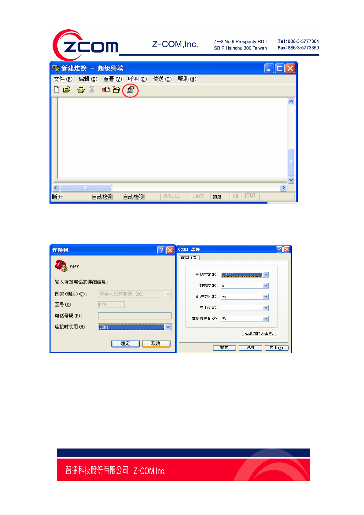
4. The Property window opens automatically. From the Communication Parameter page, select the
appropriate COM port for the connection, COM1 in this example, and 115200 for Baud Rate, 8 for
Data Bits
, None for Parity, and 1 for Stop Bits.
5. From the Property window’s Terminal page, select ANSI or VT100 for T erminal Type,
and click on OK.
Page11
Page 12
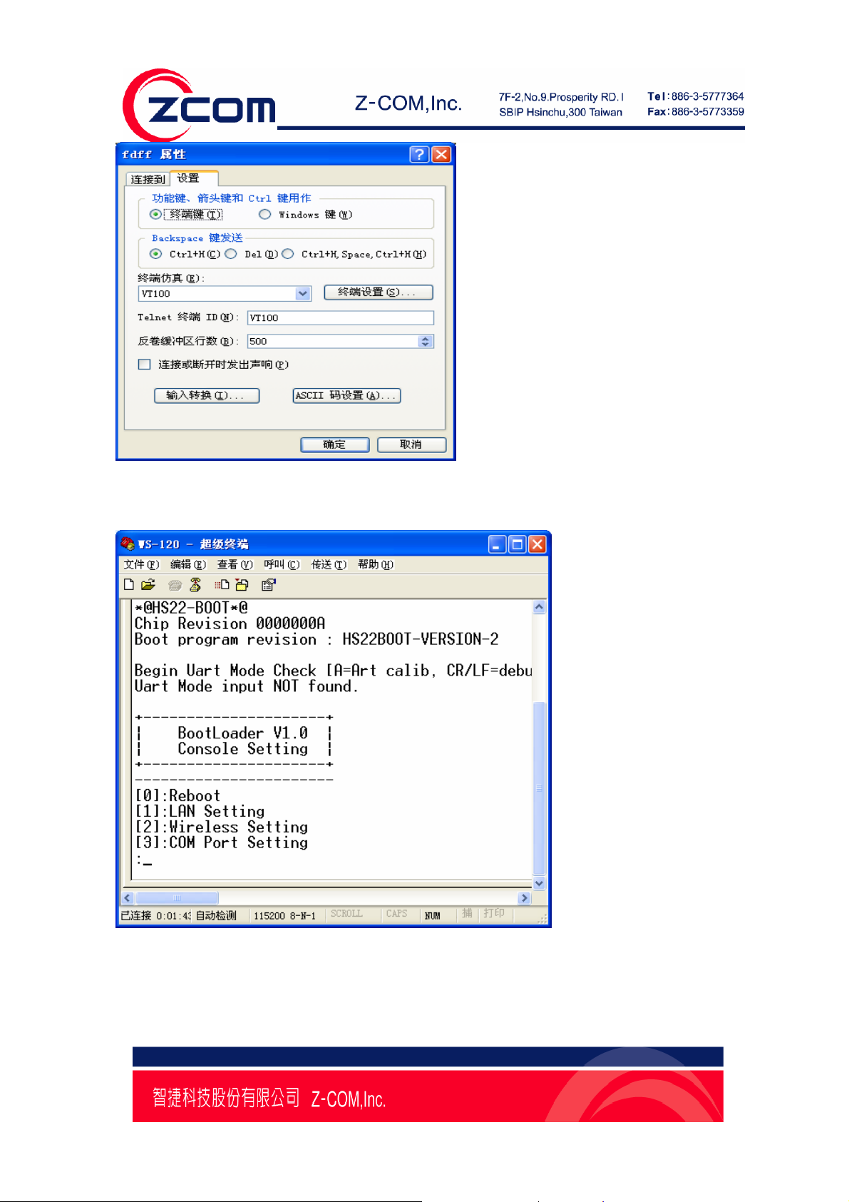
6. Press Reset button on the Nport WS-120M for 10 second, HyperTerminal will display the message
of Nport WS-120M, Shown in the following figure:
LAN Setting
When the HyperTerminal display the message of Nport WS-120M as above image . You can input 1 and
then press Enter that will display the LAN Setting message as follows:
Page12
Page 13
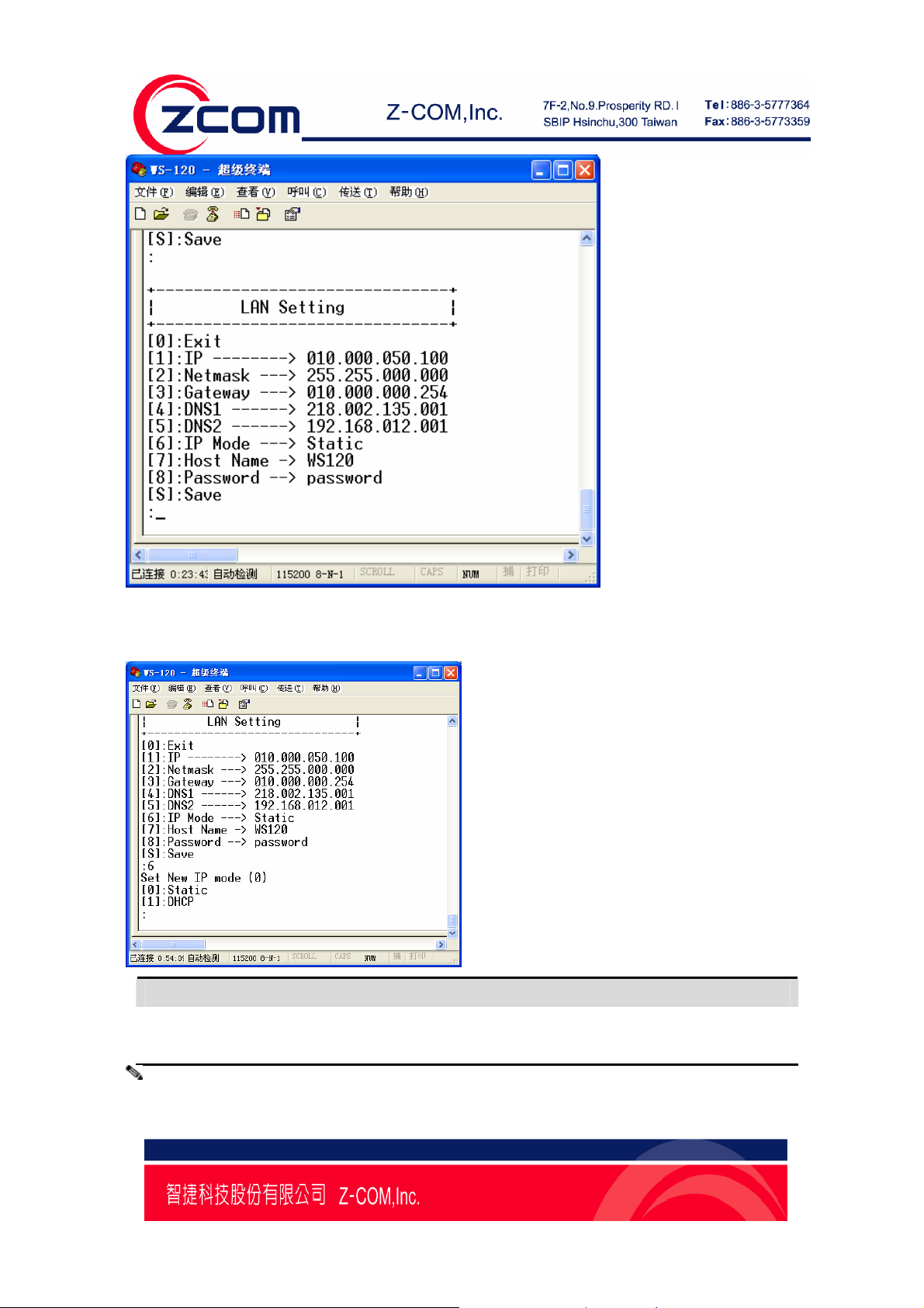
IP Mode
Input 6,you can set the IP Mode, Shown in the following figure:
Method Function Definition
Static User defined IP address, Netmask , Gateway.
DHCP DHCP Server assigned IP address, Netmask, Gateway, DNS,and Time Server.
Note:
Page13
Page 14
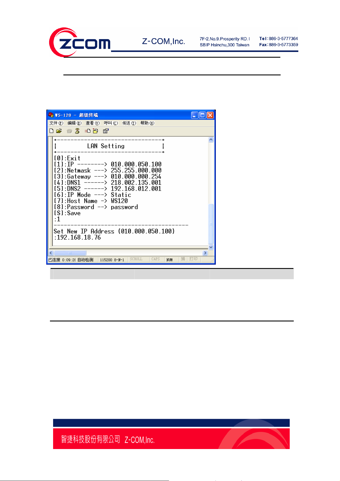
If you select Static method, that you should set IP address, Netmask, Gateway manually.
IP Address
Input 1, you can set the new IP address, Shown in the following figure:
Setting Factory Default Necessity
E.g., 192.168.18.1
(IP addresses of the form
010.000.50.100 Required
x.x.x.0
and x.x.x.255 are invalid.
An IP address is a number assigned to a network device (such as a computer) as a permanent address on
the network. Computers use the IP address to identify and talk to each other over the network. Choose a
proper IP address that is unique and valid in your network environment.
Netmask
Input 2, you can set the new Netmask, Shown in the following figure:
Page14
Page 15
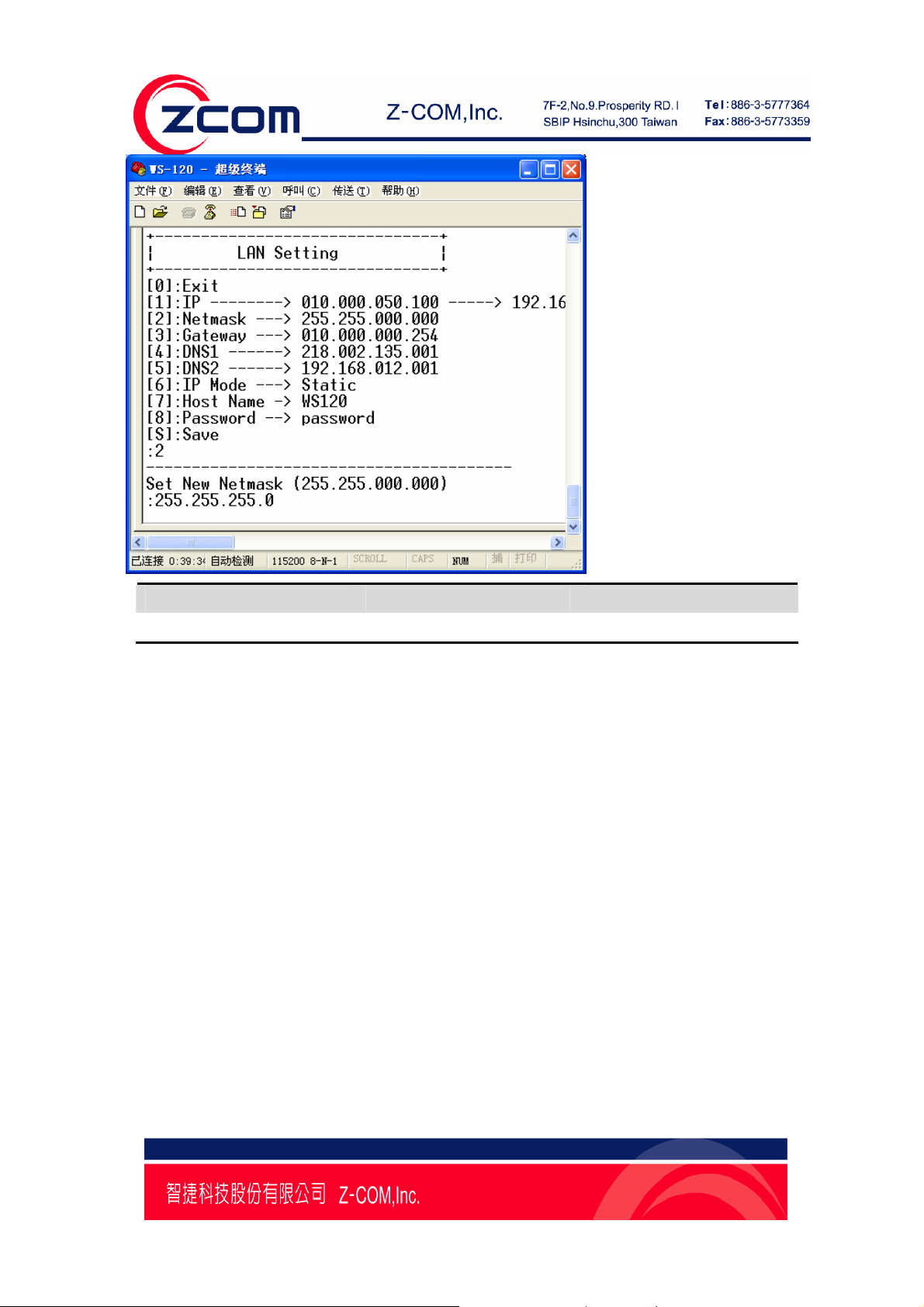
Setting Factory Default Necessity
E.g., 255.255.255.0 255.255.0.0 Required
A netmask is used to group network hosts into subnets. When a packet is sent out over the network, the
NPort WS-120M will use the netmask to check whether the desired TCP/IP host specified in the packet is
on the same subnet as the NPort. If the address is on the same subnet, a connection is established
directly between the NPort WS-120M and the host. If the host is not on the same subnet, the packet is sent
to the Gateway address.
Gateway
Input 3,you can set the new Gateway, Shown in the following figure:
Page15
Page 16

Setting Factory Default Necessity
E.g., 192.168.18.254 010.000.000.254 Optional
A gateway is a network gateway that acts as an entrance to another network. Usually, the computers that
control traffic within the network or at the local Internet service provider are gateway nodes.
NPort WS-120M needs to know the IP address of your network’s default gateway computer in order to
communicate with the hosts outside the local network en viro nment.
For correct gateway IP address information, consult your network administrator.
DNS
Input 4,you can set the new DNS, and input 5 you can set the Secondary DNS, Shown in the following
figure:
Page16
Page 17

Host Name
Input 7,you can set the new Host Name, Shown in the following figure:
Page17
Page 18

Password
Input 8,you can set the new Password, Shown in the following figure:
Save
When you changed all the setting you want to change, you should input S to save all the settings, Shown
in the following figure:
Page18
Page 19

Exit
You can input “0” to leave LAN Setting page.
Wireless Setting
When you turn into the WS-120M through HyperTerminal You can input 2 and then press Enter that will
display the Wireless Setting message as follows:
Page19
Page 20

Network Type
Input 2,you can set the Network Type of the Wireless,0 for Infrastructure mode,1 for Ad-hoc mode,
Shown in the following figure:
Page20
Page 21

SSID
Input 1, you can set the SSID of the AP or Ad-hoc that you want to connect, Shown in the following
figure:
Page21
Page 22

Ah-Hoc Channel
Input 3, you can set the Ad-hoc Channel from of the AP or Ad-hoc that you want to connect, Shown in
the following figure:
Page22
Page 23

Authentication Mode
Input 4,you can set the Authentication Mode:[0]Open,[1]WEP,[2]WPA-PSK,[3]WPA2-PSK, Shown in
the following figure:
Page23
Page 24

Key Type
Input 5, you can set the key type of WEP or PSK encryption,0 for ASC type,1 for HEX type, Shown in
the following figure:
Page24
Page 25

Key Length
Input 6,you can set the Key Length of WEP encryption:[1]64 Bits,[2]128 Bits,[3]152 Bits, Shown in the
following figure:
Page25
Page 26

Default WEP Key
Input 7, you can select the Default WEP Key the Key,
Shown in the following figure:
Page26
Page 27

WEP Key
From 8~B you can set the WEP KEY, such as when you select the Authentication Mode as WEP and
set the Default WEP Key as 2,that you should input 9 to set the WEP Key 2. Shown in the follo wing
figure:
WPA-PSK
Input C you can set the Key of WPA-PSK, such as when you select the Authentication Mode as
WPA-PSK or WPA2-PSK,that you should input C to set the key of WPA\WPA2-PSK. Shown in the
following figure:
Page27
Page 28

Save
When you changed all the setting you want to change, you should input S to save all the settings. Shown
in the following figure:
Page28
Page 29

Exit
You can input 0 to leave Wireless Setting page.
COM PORT Setting
When you turn into the WS-120M through HyperTerminal You can input 3 and then press Enter that will
display the COM Port Setting message as follows:
In COM PORT Setting you can set the Baud Rate, Data Bits,Parity Check and so on.
Baud Rate
Input 1, you can set the Baud Rate , Shown in the following figure:
Page29
Page 30

Here you can set the Baud Rate as
110,150,300,600,1200,2400,4800,9600,19200,38400,57600,115200,230400 and so on.
Data Bits
Input 3, you can set the Baud Rate , Shown in the following figure:
Page30
Page 31

Here you can set the New Data Bits as 7 or 8.
Parity Check
Input 4, you can set the Parity Check , Shown in the following figure:
Here you can set the New Parity Check, input 0 for None,1 for Odd,2 for Even,3 for Mark and 4 for
Page31
Page 32

Space.
Stop Bit
Input 5, you can set the Stop Bit , Shown in the following figure:
Here you can set the New Stop Bits as 1 or 2.
Flow Contro1
Page32
Page 33

Here you can set the New Flow Control, input 0 for None, 1 for Xon/Xoff, 2 for RTS/CTS.
Link Mode
Here you can choose the New Link Mode , input 0 for TCP Server , 1 for TCP Client , 2 for UDP.
Page33
Page 34

Virtual Com
Here you can Disable or Enable the Virtual Com , input 0 for Disable , 1 for Enable.
Pair Connection
Here you can Disable or Enable the Pair Connection , input 0 for Disable , 1 for Enable.
Page34
Page 35

Local Port
Input * you can set the Local Port.
Destination IP
Here you can set the new Destination IP Address.
Page35
Page 36

Destination Port
Here you can set the New Destination Port.
Save
When you changed all the setting you want to change, you should input S to save all the settings. Shown
in the following figure:
Page36
Page 37

Exit
You can input 0 to leave COM PORT Setting page.
Page37
Page 38

Chapter 4 Web Console Configuration
The Web Console is the most user-friendly method available to configure NPort WS-120M.
This chapter introduces the Web Console function groups and function definitions.
The following topics are covered in this chapter:
Configuring Your Browser
System
¾ Basic Setup
Wireless Setup
¾ Radio
¾ Security
Serial Server
¾ RS232 Setup
Management
¾ Change Password
¾ SNMP Setup
¾ Upgrade Firmware
¾ Backup/Restore Settings
¾ Telnet
¾ Reboot
Note:
You may use either a cross-over or straight-through Ethernet cable to connect NPort
WS-120M to a PC, Hub, or Switch. NPort WS-120M.s Ethernet port will auto-detect which
type of cable is being used, and then adjust the signals accordingly.
Configuring Your Browser
Before opening your browser , you nee d to ena ble cook ies.
Attention:
To use the Web Console, you will need to enable your browser for cookies. Your
browser’s cookie options should be located on your browser’s Internet Properties
window. Since different browsers , and different versions of the same browser are
configured differently, refer to your browser’s help section for details.
Page38
Page 39

1. Type 192.168.*.* (the IP address which get from DHCP or you set through HyperTerminal ) in
your browser’s Address box, and then press Enter.
2. Input the password if prompted. The password will be transmitted with MD5 encryption over the
Ethernet. Note that you will not be prompted to enter the password if the NPort WS-120M is not currently
password protected.
3. The NPort WS-120M homepage will open. On this page, you can see a brief description of
the Web Console’s four function groups.
Page39
Page 40

System
Basic Setup
NPort WS-120M WLAN supported IP configurations are Manual and dynamic (DHCP ).
Choose from two possible .IP configuration modes. Manual and DHCP.
IP configuration
Method Function Definition
Static User defined IP address, Netmask, Gateway.
DHCP DHCP Server assigned IP address, Netmask, Gateway, DNS,and Time Server.
IP address
Setting Factory Default Necessity
E.g., 192.168.1.1
(IP addresses of the form
192.168.1.1 Required
x.x.x.0
and x.x.x.255 are invalid.
Page40
Page 41

An IP address is a number assigned to a network device (such as a computer) as a permanent address on
the network. Computers use the IP address to identify and talk to each other over the network. Choose a
proper IP address that is unique and valid in your network environment.
Netmask
Setting Factory Default Necessity
E.g., 255.255.255.0 255.255.255.0 Required
A netmask is used to group network hosts into subnets. When a packet is sent out over the network, the
NPort WS-120M will use the netmask to check whether the desired TCP/IP host specified in the packet is
on the same subnet as the NPort. If the address is on the same subnet, a connection is established
directly between the NPort WS-120M and the host. If the host is not on the same subnet, the packet is sent
to the Gateway address.
Gateway
Setting Factory Default Necessity
E.g., 192.168.1.1 None Optional
A gateway is a network gateway that acts as an entrance to another network. Usually, the computers that
control traffic within the network or at the local Internet service provider are gateway nodes.
NPort WS-120M needs to know the IP address of your network’s default gateway computer in order to
communicate with the hosts outside the local network en viro nment.
For correct gateway IP address information, consult your network administrator.
Page41
Page 42

Wireless Setup
Radio Settings
In “Radio Setting” page, You may choose from two different WLAN modes—Infrastructure Mode and
Ad-hoc Mode—which are described in the following.
SSID
Enter the name of the wireless network (SSID) that the WS-120M is connected to.
Infrastructure Mode
In the following example, the NPort WS-120M communicates with the host computer via the AP. The host
computer connects to the AP via an Ethernet connection, allowing serial data to be transmitted back and
forth between the serial devices and host computer.
Ad-hoc Mode
In the following example, two NPort WS-120M devices establish an Ad-hoc peer-to-peer relationship,
which means that they communicate with each other directly, without going through an AP (Access
Point)..
Channel
Select a radio channel for the wireless network from the pull-down menu. In infrastructure mode, the AP
will specify the channel automatically. In Ad-hoc mode, the user must use the pull-down menu to
specify the channel.
Page42
Page 43

Security
The wireless network interface supports data encryption (WEP, 64 or 128 bits) and
WPA-PSK/WPA2-PSK encryption.
Network Authentication
Select an authentication scheme of Open System ,WPA-PSK or WPA2-PSK from the pull-down menu.
WPA Pre-Shared Key
When WPA-PSK or WPA2-PSK is enabled. You should fill the WPA Pre-Shared Key in the textbox.
WEP Key Index
Selects the Primary WEP Key for your wireless network.
WEP Key 1/2/3/4
For each of the four WEP Keys, enter the appropriate WEP Key. The WEP Keys are used to help
prevent data from being stolen as it is transmitted over public networks. The WEP Key setting(s) for the
NPort WS-120M must be the same as the WEP Key settings for the AP.
Page43
Page 44

Serial Server
RS232 Setup
Baud Rate
In the drop-down box you can select the Baud Rate of RS232
Parity
You can select the Parity from the radio button ”None, Odd, Even, Mark or Space”
Data bits
You can select the Data bits from the radio button ”7 bits or 8 bits”
Stop bits
You can select the Stop bits from the radio button ”1 bits or 2 bits”
Flow Control
You can select the Flow Control from the radio button “None, Xon/Xoff or RTS/CTS”
Transfer Layer
You can select the Transfer Layer from the radio button “TCP Server, TCP Client, UDP”
1.When you select the TCP Server, you should configure some setting of TCP Server as follows image:
Page44
Page 45

2. When you select the TCP Client, you should configure some setting of TCP Client as follows image:
3. When you select the UDP, you should configure some setting of UDP as follows image:
Page45
Page 46

Management
Change Password
You can have your desired password by changing password..
1. Take the following steps to change password.
2. Enter your currently-used password in the current field.
3. Enter your new password in the New Password field.
4. Re-enter the new password to confirm it in the Repeat New Password field.
5. Finally, click “Apply” to save the change.
(Also, if you desire to restore to the factory-set password, please click “Yes”.
The default setting is disabled.)
Page46
Page 47

SNMP Setup
In SNMP Setup you can enable and disable SNMP.
Read Community Name
When you Enable the SNMP, you should set the Read Community Name same as SNMP tool Setting.
Write Community Name
When you Enable the SNMP, you should set the Write Community Name same as SNMP tool Setting.
IP Address to Receive Traps
You can set a IP address, When SNMP tool change some setting, you can read some message from the
address.
Upgrade Firmware
Page47
Page 48

1. Open Upgrade Firmware;
2. Click Browse to select your wanted file for upgrade.
3. Click Upload to enable the file to be loaded to your WS-120M.
4. Reboot your WS-120M and check whether the firmware has been upgraded in the Basic Information.
Backup / Restore Settings
NPort WS-120M provides backup and restore for file management.
Backup:
You have access to back up the currently settings by enabling NPort WS-120M‘s Backup function.
Retrieve:
Retrieve button allows you to retrieve your backup files.
Restore:
This button can be used to clear ALL data and restore ALL settings to the factory default values.
Page48
Page 49

Telnet
In this page you can enable or disable the function of Telnet.
Reboot AP
In some cases, if you want to reboot NPort WS-120M, click Yes and then apply. WS-120M will reboot.
Page49
Page 50

If you have any further questions, please contact your local authorized reseller for support.
Zcomax Technologies, Inc.
14545 VALLEY VIEW
California Business
Center
AVE., SUITE "S"
SANT A FE SPRINGS, CA
90670
NewJersey
Business Center
98 Ford Road, Suite 3-F,
Denville, NJ 07834, USA
ZCOMAX - United Kingdom Limited
European
19 Colindale Avenue
Business Centre
London NW9 5DS UK
Tel: +1-562-926-4588
Fax:+1-562-926-7885
Tel: +1-973-664-0310
Fax:+1-973-664-0313
Tel: +44-(0)-20-8982-8200
Fax:+44-(0)-20-8201-3232
Sales/Product Inquiries:
sales@zcomax.com
Tech Support/Questions:
support@zcomax.com
Sales Contact
sales@zcomax.co.uk
FAE Support
support@zcomax.co.uk
Page50
 Loading...