

Page 1
IIEEEEEE 880022..1111bb//gg W
Wiirreelleessss IIPP PPhhoonnee
Model: WP-520
User Manual
Version: 1.0
Date of Issue: September 2007
Page 2

FCC Information
This device complies with Part 15 of the FCC Rules. Operation is subject to the
following two conditions: (1) this device may not cause harmful interference, and (2)
this device must accept any interference received; including interference that may
cause undesired operation.
Federal Communications Commission (FCC) Statement
This Equipment has been tested and found to comply with the limits for a Class B
digital device, pursuant to Part 15 of the FCC rules. These limits are designed to
provide reasonable protection against harmful interference in a residential installation.
This equipment generates uses and can radiate radio frequency energy and, if not
installed and used in accordance with the instructions, may cause harmful
interference to radio communications. However, there is no guarantee that
interference will not occur in a particular installation. If this equipment does cause
harmful interference to radio or television reception, which can be determined by
turning the equipment off and on, the user is encouraged to try to correct the
interference by one or more of the following measures:
- Reorient or relocate the receiving antenna.
- Increase the separation between the equipment and receiver.
- Connect the equipment into an outlet on a circuit different from that to which the
receiver is connected.
-Consult the dealer or an experienced radio/TV technician for help.
Warning: Any changes or modifications to this unit not expressly approved by
the party responsible for compliance could void the user authority to operate
the equipment.
Trade name
Model number
FCC RF Radiation Exposure Statement:
Page 3

1. This Transmitter must not be co-located or operating in conjunction with any other antenna or transmitter.
IMPORTANT NOTE:
Federal Communication Commission (FCC) Radiation Exposure Statement
This EUT is compliance with SAR for general population/uncontrolled exposure limit in ANSI/IEEE C95.1-1999 and
had been tested in accordance with the measurement methods and procedures specified in OET Bulletin 65 Supplement C.
This equipment should be installed and operated with minimum distance 1.5 cm between the radiator & your body.
To maintain compliance with FCC RF exposure requirements, use only belt-clips, holsters or similar accessories that does not
contain metallic components in its assembly.
The use of accessories that do not satisfy these requirements may not comply with FCC RF exposure requirements,
and should be avoided.
For product available in the USA market, only channel 1~11 can be operated. Selection of other channels
is not possible.
CE Statement:
Hereby, Z-Com, Inc.
relevant provisions of the R&TTE Directive 1999/5/EC. This device will be sold in the following EEA countries:
Austria, Italy, Belgium, Liechtenstein, Denmark, Luxembourg, Finland, Netherlands, France, Norway, Germany,
Portugal, Greece, Spain, Iceland, Sweden, Ireland, United Kingdom,Cyprus, Czech Republic, Estonia, Hungary,
Latvia, Lithuania, Malta, Slovakia, Poland, Slovenia, Bulgaria, Romania.
declares that this device is in compliance with the
essential requirements and other
依據 低功率電波輻射性電機管理辦法
第十二條 經型式認證合格之低功率射頻電機,非經許可,公司、商號或使用者均不得
擅自變更頻率、加大功率或變更原設計之特性及功能。
第十四條 低功率射頻電機之使用不得影響飛航安全及干擾合法通信;經發現有干擾現
象時,應立即停用,並改善至無干擾時方得繼續使用。前項合法通信,指依
電信規定作業之無線電信。低功率射頻電機須忍受合法通信或工業、科學及
醫療用電波輻射性電機設備之干擾。
Page 4

Copyright
Copyright © 2007 all rights reserved. No part of this publication may be reproduced,
adapted, stored in a retrieval system, translated into any language, or transmitted in
any form or by any means without the written permission of the supplier.
About This Manual
The purpose of this manual is for the setup of the IEEE 802.11bg Wireless VoIP
Phone. This manual includes procedures assisting you in avoiding unforeseen
problems.
Page 5

Table of Contents
Chapter 1 Introduction.......................................................................................7
1-1 Features and Benefits ......................................................................................7
Chapter 2 Installing and Using the WP-520.....................................................8
2-1 Product Kit........................................................................................................8
2-3 Mechanical Description ....................................................................................8
2-4 Hardware Installation........................................................................................9
2-5 Main Menu........................................................................................................9
2.5.1 LCD Screen:.............................................................................................9
2.5.2 Call Log:.................................................................................................10
2.5.3 User Profiles:..........................................................................................10
Chapter 3 Start to use the WP-520..................................................................12
Chapter 4 Configuring the WP-520 Settings..................................................14
4.1 Date/Time.......................................................................................................14
4.2 Phone Setting.................................................................................................14
4.2.1 Language: ..............................................................................................14
4.2.2 Phone lock: ............................................................................................14
4.2.3 Backlight:................................................................................................15
4.2.4 Quick Button:..........................................................................................15
4.2.5 FW upgrade: ..........................................................................................15
4.2.6 Restore factory:......................................................................................16
4.3 Call Setting.....................................................................................................16
4.3.1 Forward:.................................................................................................16
4.3.2 Send Caller ID:.......................................................................................16
4.4 Information......................................................................................................16
4.4.1 TCP/IP:...................................................................................................17
4.4.2 WLAN:....................................................................................................17
4.4.3 SIP: ........................................................................................................17
4.4.4 HW Info:.................................................................................................17
4.4.5 Log:........................................................................................................17
Chapter 5 Network Settings............................................................................18
5.1 Site scan.........................................................................................................18
5.2 Network config................................................................................................18
5.2.1 WLAN Profiles:.......................................................................................18
Page 6

5.2.2 SIP Profiles:............................................................................................20
5.2.3 Wireless Security:...................................................................................21
5.2.4 WPS:......................................................................................................22
5.3 Ping test..........................................................................................................22
5.4 Re-connect.....................................................................................................22
Chapter 6 Special Call Function .....................................................................23
6.1 Call Hold/Unhold.............................................................................................23
6.2 Call Transfer...................................................................................................23
6.3 3-Way Conference Call...................................................................................23
6.4 P2P Call (Peer to Peer)..................................................................................23
Chapter 7 Firmware Upgrade..........................................................................25
7.1 Web Upgrade .................................................................................................25
7.2 HTTP Server...................................................................................................26
Chapter 8 Trouble Shooting............................................................................28
1. No WLAN Service...........................................................................................28
2. No SIP Service................................................................................................28
3. Register Failed................................................................................................28
Limited Warranty................................................................................................29
Distributor Information.......................................................................................32
Page 7

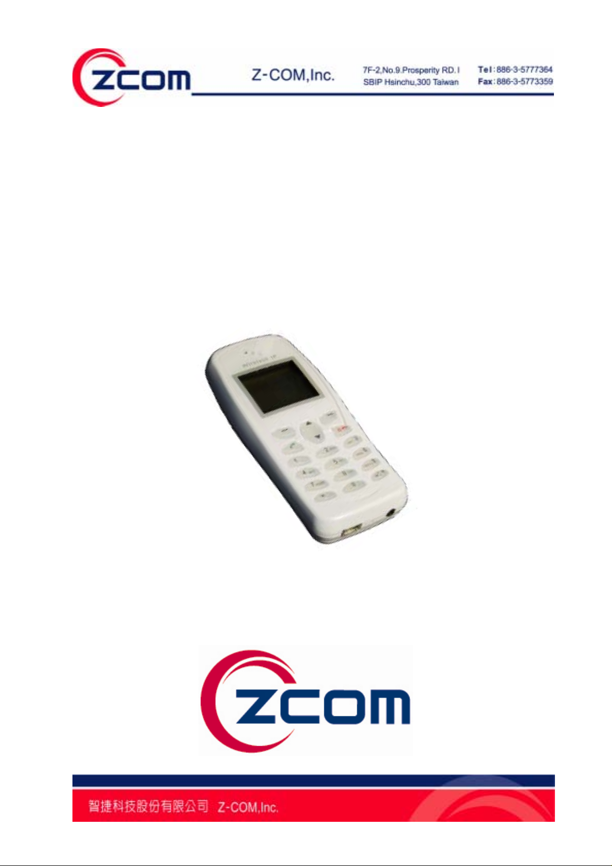
Chapter 1 Introduction
Thanks for purchasing of WP-520, the outstanding Wireless VoIP Phone. The
WP-520 can easily connect to the wireless router or Access Point and enables to
make and receive call simply in any wireless networking environment. With the
advance wireless security solution, the WP-520 not only ensures the high voice
quality but also avoids the attacks from the hackers.
1-1 Features and Benefits
Availability and Mobility
The WP-520 design is based on SIP v2 (Session Lnitiation Protocol version 2,
RFC 3261) open standard, which is interoperable with major SIP-based call
servers, IP-PBXs, and other standard SIP-based client devices. The WP-520
enables the user to make and receive phone calls at home, the office, WiFi cafés,
airports, hotels, at a school campus or anywhere with the IEEE 802.11 b/g
wireless networking access. Its seamless roaming capacity between the access
points also certifies for uninterrupted calls and secures the data connections
while roaming in the wireless networking environment. This small handset design
is easy to transport and makes it simple to talk to family, friends and colleagues
all over the world.
High Voice Quality with Low Communication Cost
With the growing number of hotspots and metropolitan areas that provide low- or
no-cost high-speed WiFi environments, the WP-520 user can use the device
easily without paying bills to standard telephone services. Moreover, the WP-520
supports QoS (Quality of Service) which ensures the priority of voice and data
traffic for high voice quality.
Easy Security Setup and high Security Protection
With the WPS (WiFi Protected Setup) function, the highest security level will be
established automatically between the Access Point and the WP-520 to protect
the voice traffic from hackers or unauthorized users. The WP-520 supports WEP,
WPA (2) Personal and Enterprise encryption as well.
Ultra Low power consumption
Through exclusive power saving design with WMM-UAPSD (Unscheduled
Automatic Power Save Delivery) supported, the WP-520 enables to reduce
power consumption to extremely low levels.
7
Page 8
Chapter 2 Installing and Using the WP-520
This chapter provides the instructions for first-time installation and basic use of the IP
Phone. It also describes initial setup of the WP-520.
2-1 Product Kit
Before installing, please make sure that you have the following items:
The 54Mbps Wireless VoIP Phone…………………………….…………x 1
Power Adapter…..……………………………….…………..……………...x 1
3.7V, 920mAh Lithium Battery …………………………………………...x 1
Product CD ..…………………………………………………………………x 1
If any of the above items is not included or damaged, please contact to your local
dealer for support.
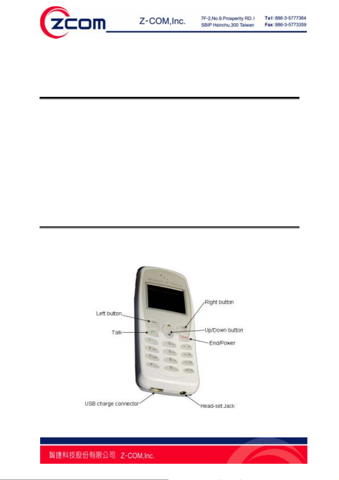
2-3 Mechanical Description
Panel of the VoIP Phone:
8
Page 9
2-4 Hardware Installation
Take the following steps to set up your Access Point.
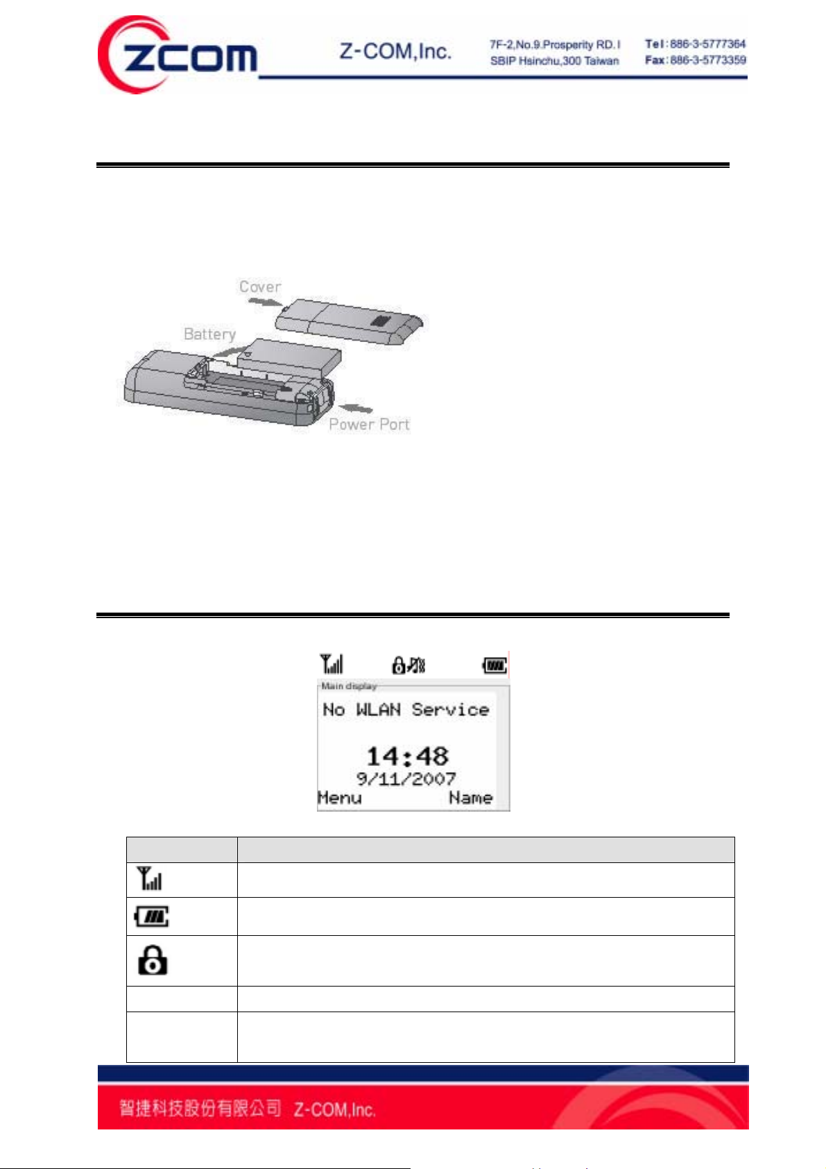
Inserting the Phone’s Battery
Charging the IP Phone’s Battery
1. Connect the power adapter to USB charge connector.
2. Charge battery for 10 hours to fully charge battery when first time using.
2-5 Main Menu
2.5.1 LCD Screen:
LABLE Description
Time/Date
Status
The drawing shows the wireless LAN signal strength.
The drawing shows the current battery power remaining.
The drawing shows the status of phone lock. You can press “#”
and left button to lock and unlock the keypad.
The time and date display on center of the screen.
The status displays on top center of the screen. And the statuses
are including wireless LAN connection status and SIP server
9
Page 10
Menu
register status.
The drawings show the ring mode, include ring, vibrate, or ring
and vibrate.
Press left button to enter main menu to setup the WP-520.
Name
Press right button to add or find phone number in telephone
directory.
# Press # button to change the input language.
*
Change current user profile to Meeting mode user profile. Press
* button and hold more than 3 second.
2.5.2 Call Log:
You may check the list of Missed calls, Received calls, and Dialed calls or to delete
all call lists.
Press left (Menu) button, and 1 Call log to check the call list.
Option Description
Missed calls Display the list of missed calls recently.
Received calls Display the list of received calls recently.
Dialed calls Display the list of dialed calls recently.
Delete all Delete all lists of missed calls, received calls, and dialed calls.
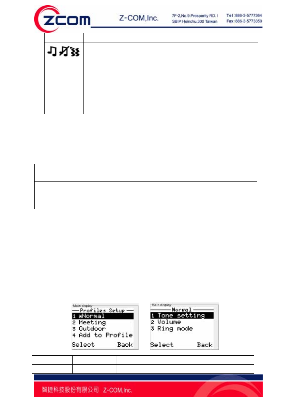
2.5.3 User Profiles:
The WP-520 provides 3 default types of user profile to let your personalize tone
setting, Volume and ring mode. You can also add your user profile to personalize
phone setting. The maximum numbers of the new created user profile that the
WP-520 supports are 7 user profiles.
Press left (Menu) button, 2 Profiles to select the user profile that you want to
personalize.
There are Normal, Meeting, and Outdoor 3 types of the profile for default use. You
can add a new profile by yourself as well.
Option Suboption Description
Tone setting Ring tones Provide 14 kinds of ring tone to let user select.
10
Page 11

Key tone To turn on/off the keypad tone.
Volume
Ring mode
Ring Vol. To configure the ring volume to loud or soft.
Receiver Vol. To configure the receiver volume to loud or soft.
Speaker Vol. To configure the speaker volume to loud or soft.
Key tone Vol. To configure the keypad tone volume to loud or
soft.
Ring only Configure ring mode to ring only.
Vibrate Configure ring mode to vibrate without ring.
Ring and Vib. Configure ring mode to ring and vibrate at the
same time.
Vib. then Ring Configure ring mode to vibrate first and then ring.
Silent Configure ring mode to silent which means that the
WP-520 won’t ring or vibrate when a call coming.
11
Page 12

Chapter 3 Start to use the WP-520
This chapter provides instructions to setup the Wp-520 when the first time using. You
may configure your WP-520 with the following steps.
Powering on the WP-520, you will see the welcome display.
1 Configure the information of your SIP server
Step1. Press Menu→4 Network→2 Network Config and
select 2 SIP Profiles to create SIP profile or active SIP
profile.
Step2. To add a new SIP profile, please edit profile name
first. Then, configure the following items in next page. 1
Display Name, 2 Phone Number, 3 SIP Server, 4 SIP
Proxy, 5 STUN Server, 6 Outbound Proxy, 7 Expire, 8
Forward, and 9 Codec Order.
Step3. Input the profile name and phone number when
selecting 1 Display Name and 2 Phone Number.
Step4. Setup SIP server IP address and port when
selecting 3 SIP Server.
12
Page 13

2 Connect to a wireless network
Step1. Press Left button (Menu) to enter main menu.
Step2. Select 4.Network to enter network setting.
Step3. Select 1.Site Scan to choose AP that you want to
connect from scan list, 2. Network Config to create WLAN
profile.
Step4. When entering 2 Network Config, please select 1
WLAN Profiles to configure profile settings.
Step5. To add a new profile, please select 3 Add to Profile
and setup 1 SSID, 2 Security Setup, 3 IP Setup, and 4
SIP Binding in the next page.
Step6. After editing SSID, please select 2 Security Setup
to establish the wireless security. There are six items for
selection, 1 Open, 2 WEP, 3 WPA PSK/TKIP, 4 WPA2
PSK/AES, 5 WPA-EAP, 6 WPA2-EAP.
Step7. After setting the wireless security, please select 3 IP
Setup to set up the IP address for the WP-520. There are
three items for selection, 1 Use DHCP, 2 Use Static IP,
and 3 Use PPPOE.
Step8. When select 3 WPS, you may choose 1 PBC mode
or 2 PIN mode which use default PIN to connect to WPS
AP.
After setting up the WLAN profile and SIP profile, the WP-520 will start to register on
SIP server. If registration successes, the WP-520 screen will display phone number
that you set in SIP profile.
13
Page 14

Chapter 4 Configuring the WP-520 Settings
This chapter describes the way to set up the WP-520 and the way to check the
hardware and software information.
4.1 Date/Time
The Date/ Time menu allows you to set the WP-520’s date and time settings.
Press left (Menu) button, 3 Setup, and 1 Time/ Date to enter Time/ Date setup
menu.
Option Description
1 Set Time/Date You can set the date and time that display on the WP-520
screen.
2 Auto Clock Sync. The WP-520 can enable or disable to update the time from an
NTP server. After enable this function, input the NTP server IP
address to sync.
3 Set Time Zone You can set the local time zone.
4.2 Phone Setting
You may configure the basic settings of the WP-520 here. Press left (Menu) button, 3
Setup, and 2 Phone Setting to configure the basic settings.
There are 1 Language, 2 Caller ID, 3 Phone lock, 4 Backlight, 5 Quick button, 6 FW
update, and 7 Restore factory for configuration.
4.2.1 Language:
You can select language which you want to display. The default language is English.
4.2.2 Phone lock:
If you did not use the WP-520, you may set the idle time to make the WP-520 lock
the keypad. There are off, 15s, 30s, 60s, and 120s for selection. When the WP-520
keypad is locked, press # and left button to unlock the keypad.
14
Page 15

4.2.3 Backlight:
You may set up the backlight remain time to control the back light remain. There are
off, 4s, 7s, 10s, and Always on for selection.
4.2.4 Quick Button:
You may set the Up and Down buttons as quick button. There are 4 functions can be
set to quick button.
Press left (Menu) button, 3 Setup, 2 Phone Setting, and 5 Quick Button to set up.
Option Description
1 P2P Dialing Allow you to make a Point to Point call.
2 Speaker Volume Allow you to increase or decrease the speaker volume.
3 Receiver Volume Allow you to increase or decrease the receive volume.
4 Profiles Allow you to enter user profile menu.
4.2.5 FW upgrade:
You may login a HTTP server to upgrade the WP-520 firmware.
Press left (Menu) button, 3 Setup, 2 Phone Setting, and 6FW update to set up the
HTTP server information.
Option Description
1 Upgrade Now Start to upgrade firmware.
2 Server Address Allow you to set up the HTTP server IP address.
3 Server Port Allow you to set up the HTTP server port.
The more detail upgrade steps, please refer to Chapter 6.2.
15
Page 16

4.2.6 Restore factory:
You may reset the Wi-Fi phone settings to factory default by selecting this item. The
settings will be reset include user profile, phone settings, wireless and SIP profiles,
but not include the phone book.
4.3 Call Setting
You may configure the basic call settings of the WP-520 here. Press left (Menu)
button, 3 Setup, and 3 Call Setting to configure the basic settings.
4.3.1 Forward:
Select “On” to enable this function, then input the forward phone number and select
the forward condition. There are 4 forward conditions provided: Always, Busy, No
Answer, and Busy & No Answer.
Forward Type Description
Always Always forward the call to the forward number no matter you
are busy or not.
Busy Forward the call to the forward number when you are busy.
No Answer Forward the call to the forward number when you are no
answer. You can set the no answer time which by selecting
10s, 15s, 20s, or other (input the expected time by yourself).
Busy & No Answer Forward the call to the forward number when you are busy or
no answer. You can set the no answer time which by selecting
10s, 15s, 20s, or other (input the expected by yourself).
4.3.2 Send Caller ID:
Select “On” to enable this function. If the SIP server support send caller ID, your
phone number will be displayed on the screen of the receivers’ that you call out.
4.4 Information
The WP-520 provides information check function. You may check the status of
WP-520 via this item. Press left (Menu) button, and select 3 Setup, 3 Information to
select the item that you want to check.
16
Page 17

4.4.1 TCP/IP:
You may check the WP-520 IP address, Subnet Mask, Gateway, and DNS by select
this item.
Note: If the Wi-Fi phone doesn’t connect to an Access Point, and it will show
“Network Not Up Yet!”
4.4.2 WLAN:
You may check the WP-520 wireless LAN information by select this item. The
wireless information is including SSID, BSSID, Channel, and Security.
4.4.3 SIP:
You may check the SIP server information that the WP-520 is registered. The SIP
server information is including Phone Number, SIP Server IP address, SIP Proxy,
Outbound Proxy, Stun Server, and Expire time.
4.4.4 HW Info:
You may check the hardware information of the WP-520 by selecting this item. The
information is including Storage Free, FW version, and MAC Address.
4.4.5 Log:
The WP-520 provides system log to let you check the system events. The system
logs are including wireless connection and network information.
17
Page 18

Chapter 5 Network Settings
This Chapter will give you the instruction step by step to configure the WP-520 to
connect to your wireless Access Point and to register on your SIP server on the
Internet. Press left (Menu) button, 4 Network to enter Network setting items.
5.1 Site scan
When entering the Network setting page, the first item is Site scan. You may select
Site scan to scan available Access Points in the environment. You can connect to an
Access Point directly by select SSID at this page or to add a new WLAN profile to set
up SSID. You may set up the security and IP address after select SSID, and the
WP-520 will connect to the Access Point which is selected.
5.2 Network config
5.2.1 WLAN Profiles:
You can search and configure a WLAN profile from WLAN profile list, or add a new
profile or enter WPS settings to set up the WPS mode.
¾ Add New WLAN Profile
You can add a new WLAN profile and edit for wireless connection.
Press left (Menu) button → 4 Network → 2 Network config → 1 WLAN
Profiles → 2 Add to Profile to add a new profile.
Enter the Add to Profile page; you can set up 1 SSID, 2 Security setting, and IP
18
Page 19

Setup such as the picture below.
¾ WLAN Profile List
You can search a WLAN profile that had been created before and edit it for
wireless connection.
Press left (Menu) button → 4 Network → 2 Network config → 1 WLAN
Profiles → 1 Profiles List to select the wireless profile or edit it. You may
configure more detail setting follow the table description below when editing
wireless profile.
Option Description
SSID Input the SSID that you want to connect.
Security Setting Setup the security way that the SSID you connected.
1. WEP: You may setup WEP key, key index, and
Authen T ype.
2. WPA (2) PSK: You may input the WPA-PSK or
WPA2-PSK key to associate with Access Point. The
WPA-PSK only supports TKIP cipher and WPA2-PSK
only supports AES cipher.
3. WPA (2)-EAP: You may set up the user name,
password, and EAP type. There are 3 options for
EAP type, Auto, TTLS, and PEAP.
IP Setup Set up the way to get the IP address.
1. DHCP: Select DHCP to let the WP-520 get IP
address from DHCP server.
2. Static IP: Allow you to set up the WP-520 static IP
address, Netmask, Gateway, and DNS.
3. PPPoE: The WP-520 can be the PPPoE client, and
you can dial-up to the ADSL by input the PPPoE user
name and password that the ISP provided.
19
Page 20

¾ WPS
The Wp-520 provides the WPS feature that can connect to the WPS enable
Access point.
Press left (Menu) button, 4 Network, 2 Network config, and 3 WPS to enter
WPS setting menu.
There are two modes supporting for the WPS link. One is PBC mode, the other
is PIN mode. When selecting PBC mode, the WP-520 will start to scan Access
Point that start PBC mode at the same time. When selecting the PIN mode, the
WP-520 will generate a PIN key randomly, and the Access Point which enables
the PIN mode should input the key that the WP-520 generates.
5.2.2 SIP Profiles:
¾ Add New SIP Profile
You can add a new SIP profile and edit for SIP server register.
Press left (Menu) button → 4 Network → 2 Network config → 2 SIP
Profiles → 2 Add to Profile to add a new profile.
After inputting SIP profile name, you can set up the phone number, and the
address of SIP server, SIP proxy, and NAT traversal, SIP server expire time,
forwarding phone number and Codec order.
¾ Profile List
You can search a SIP profile that had been created before to active or inactive it
and edit it for SIP server register or delete the profile.
Press left (Menu) button → 4 Network → 2 Network config → 2 SIP
Profiles → 1 Profile List to search a profile.
The more detail description refers to the table below when edit SIP profile.
Option Description
1 Display Name Input the profile name that you want to display.
2 Phone Number Input the phone number that you register on SIP server.
20
Page 21

3 SIP Server Input the SIP server IP address and port. The port default
value is 5060.
4 SIP Proxy Input the SIP server IP address, port, user name, and
password. The port default value is 5060.
5 NAT traversal 1 STUN Server
Input the STUN server IP address and STUN server port.
The port default value is 3478.
2 Outbound Proxy
Input the outbound proxy IP address and outbound proxy
port. The proxy port default value is 5082.
3 NAT keep Alive Time:15s
6 Expire Input the SIP server expire time. The default value is 3600.
7 Forward Enable forward function, input forward number and select
forward type.
8 Codec Order Change the Codec Order for really use. The default order is
G.711, G.726.
5.2.3 Wireless Security:
Unlike wired network data, your wireless data transmissions can extend beyond your
walls and can be received by anyone with a compatible adapter. For this reason, use
the security features of your wireless equipment.
WEP
To prevent unauthorized wireless stations from accessing data transmitted over the
network, the Access Point Security Settings window offers the WEP features, making
your data transmission over air more secure and allows you to specify Encryption
Key(s) if you enable encryption for the Access Point.
The Wi-Fi phone support WEP 64 bits and 128 bits key length.
You may input key value manually:
64 bits WEP: Enter 5 ASCII characters or 10 hexadecimal digits (between 0-9, a-f
and A-F).
128 bits WEP: Enter 13 ASCII characters or 26 hexadecimal digits (between 0-9, a-f
and A-F).
Note: The WEP key must be set up exactly the same on the Wireless Access Points
as they are on the wireless clients. If you set “0011223344” for the Wireless Access
Point, the same WEP key “0011223344” must be assigned to other client stations.
WPA (2)
The WP-520 supports WPA (2) Personal and Enterprise security. Wi-Fi Protected
21
Page 22

Access (WPA) is a subset of the IEEE 802.11i standard. WPA2 is a wireless security
standard that defines stronger encryption, authentication and key management than
WPA. You may select WPA (2) – PSK for WPA (2) Personal, or WPA (2) – EAP for
WPA (2) Enterprise. When you select WPA (2) – PSK, you should input key from 8 to
63 ASCII characters, or input the key from 8 to 64 Hex characters.
5.2.4 WPS:
The WPS (Wi-Fi Protected Setup) feature is defined by Wi-Fi Alliance and the
primary goal is to simplify the security setup and management of Wi-Fi networks.
The WP-520 supports to be WPS client to connect to the Access Point which
supports the WPS.
The WP-520 supports two types of WPS configuration mode including PBC and PIN
mode.
Select PBC to search and connect the Access Point that has to push the WPS
button.
Select PIN mode to generate a security key (length 8 HEX), and input the key to
Access Point which configure PIN mode.
5.3 Ping test
The WP-520 provides the ping test function to let you check the network. You can
select the ping destination to do the ping test. There are 6 ping destinations to let you
select. When you select 1 Manual, input the manual IP address to be the ping
destination. When you select 2 Gateway, the gateway that the WLAN profile set will
be the ping destination. When you select 3 DNS, the DNS that the WLAN profile set
will be the ping destination. When you select 4 SIP server, the SIP server that the
SIP profile set will be the ping destination. When you select 5 SIP Proxy, the SIP
proxy that the SIP profile set will be the ping destination. When you select 6
Outbound Proxy, the Outbound Proxy that the SIP profile set will be the ping
destination. When you select 7 Stun Server, the STUN server that the SIP profile set
will be the ping destination.
5.4 Re-connect
The WP-520 provides Re-connect option to let user reconnect to Access Point.
22
Page 23

Chapter 6 Special Call Function
The WP-520 provides some special call functions, including call hold, call transfer,
and call conference etc.
6.1 Call Hold/Unhold
You may hold or unhold a call by selecting call options when you call out or answer a
call. Press left (call option) button to enter call options and select 1 Hold/Unhold.
Usually, you can use this function if you want to make a new call to the third user or
transfer the call to the other one.
6.2 Call Transfer
The WP-520 supports blind transfer and consultative transfer. Blind transfer means
passing a call without modifying the recipient. The consultative transfer means
allowing the recipient to be the agent to consult with destination recipient before
transferring the call. Subsequently, the agent recipient can reconnect to the caller or
transfer the caller to the destination recipient.
You may transfer a call by selecting call options when you call out or answer a call.
Press left (call option) button to enter call options and select 3 Transfer. You may
transfer this call to the third user.
6.3 3-Way Conference Call
You may make a conference call by selecting call options when you call out or
answer a call. Press left (call option) button to enter call options and select 4 New
call. After the third user answered, press left (call option) button to enter call options
and select 5 conference to establish a conference call.
6.4 P2P Call (Peer to Peer)
You can use phone number and WP-520 IP address to make a P2P call via your
wireless network without passing through SIP server.
Step1. Create a WLAN profile to connect to a wireless Access Point and set static IP
to Wi-Fi phone.
Step2. Create a SIP profile and set the phone number of your WP-520.
Step3. In the main screen, press UP button (Note) to input call out phone number, IP
address, and P2P Port (default is 5060). Then, the screen will display “Start P2P
23
Page 24

dialing?” Press left button to start P2P call.
Note: The quick button depends on the user profile that user had set up, and
the factory default UP button is for P2P call.
24
Page 25

Chapter 7 Firmware Upgrade
The WP-520 provides two ways to let user upgrade the firmware. One is download
the firmware and store it in local laptop, then, upgrade the firmware via local network.
The other is login the Internet HTTP server and upgrade firmware directory.
7.1 Web Upgrade
One laptop <or personal computer> and one Access Point are required to do the web
upgrade. Ensure the Access Point connect to the laptop by the Ethernet like the
illustration. The firmware can be upgraded by the following steps.
Step1. Download the firmware file in your laptop from the manufacturers’ websites.
Step2. Press left (Menu) button, 4 Network, and 1 Site scan to search the Access
Point which has connected to the laptop had the latest firmware.
Step3. Set up the IP address of WP-520 to the Static IP and the IP address which is
the same subnet mask with the Access Point and the laptop. Then, ping the IP
address of WP-520 from laptop to ensure if the network has connected.
Step4. Open the browser and input the IP address of WP-520. Then, it will enter the
Wi-Fi phone web access page like picture below. Input the password to login the web
page. The default value is “password”.
25
Page 26

Step5. Expend the left main menu first. Select the Upgrade Firmware to enter the
firmware upload page. Click Browser icon to allocate the firmware file path, then, click
Upload.
Step6. When starting uploading, the screen of WP-520 will display Upgrading. If the
upgrade finished, the screen of WP-520 will display Upgrade success. Power off the
WP-520 and power on again, the new firmware will be work.
7.2 HTTP Server
One Access Point is required to connect with the Internet. The instructions of
upgrading the WP-520 are as bellows:
26
Page 27

Step1. Press left (Menu) button, 4 Network, and 1 Site scan to search the Access
Point which connects to the Internet or select an existed WLAN profile to connect to
Access Point.
Step2. Press left (Menu) button, 3 Setup, 2 Phone Setting, and 6 FW update.
Step3. Select 2 Server Address to input the HTTP server IP address which provided
by the manufacturers, and select 3 Server Port to input the HTTP protocol port. The
default value is “80”.
Step4 After connecting to an Access Point, and set up the information of HTTP server.
Then, select 1 Upgrade Now to upgrade the firmware directory.
27
Page 28

Chapter 8 Trouble Shooting
The trouble shooting provides the solutions to solve the problems that may occur
during installation or using the WP-520. If you can’t find the solutions by the following
description, please content to your local commercial agent.
1. No WLAN Service
1. Check the power adapter of Access Point.
2. Use site scan to check the Access Point signal strength.
3. Let the WP-520 re-associate the Access Point.
4. Check the security setting of the WP-520.
2. No SIP Service
1. Check if the IP address of SIP server inputted in the SIP profile is correct.
3. Register Failed
1. Check the user name and password if corrected.
28
Page 29

Limited Warranty
This Warranty constitutes the sole and exclusive remedy of any buyer or reseller’s
equipment and the sole and exclusive liability of the supplier in connection with the
products and is in lieu of all other warranties, express, implied or statutory, including,
but not limited to, any implied warranty of merchantability of fitness for a particular
use and all other obligations or liabilities of the supplier.
In no even will the supplier or any other party or person be liable to your or anyone
else for any damages, including lost profits, lost savings or other incidental or
consequential damages, or inability to use the software provided on the software
media even if the supplier or the other party person has been advised of the
possibility of such damages.
The following are special terms applicable to your hardware warranty as well as
services you may use during part of the warranty period. Your formal Warranty
Statement, including the warranty applicable to our Wireless LAN products, appears
in the Quick Installation Guide which accompanies your products.
Duration of Hardware Warranty: One Year
Replacement, Repair or Refund Procedure for Hardware:
If your unit needs a repair or replacement, return it to your dealer/distributor in its
original packaging. When returning a defective product for Warranty, always include
the following documents:
The Warranty Repair Card
A copy of the invoice/proof of purchase, and
The RMA Report Form (To receive a Return Materials Authorization form (RMA),
and please contact the party from whom you purchased the product).
Upon proof-of-purchase we shall, at its option, repair or replace the defective item at
no cost to the buyer.
This warranty is contingent upon proper use in the application for which the products
29
Page 30

are intended and does not cover products which have been modified without the
reseller’s approval or which have been subjected to unusual physical or electrical
demands or damaged in any way.
30
Page 31

Please complete the information below and include it along with your products.
Name:
Title:
Company:
Telephone:
Fax:
Email:
City/State/Zipcode:
Country:
Product Name:
Serial Number:
MAC Address:
Invoice Date:
Product Description:
If you have any further questions, please contact your local authorized reseller for
support.
31
Page 32

Distributor Information
Zcomax Technologies, Inc.
California Business
Center
New Jersey
Business Center
ZCOMAX - United Kingdom Limited
European Business
Centre
14545 VALLEY VIEW AVE.,
SUITE "S"
SANTA FE SPRINGS, CA
90670
98 Ford Road, Suite 3-F,
Denville, NJ 07834, USA
19 Colindale Avenue
London NW9 5DS UK
Tel: +1-562-926-4588
Fax:+1-562-926-7885
Tel: +1-973-664-0310
Fax:+1-973-664-0313
Tel: +44-(0)-20-8982-8200
Fax:+44-(0)-20-8201-3232
Sales/Product Inquiries:
sales@zcomax.com
Tech Support/Questions:
support@zcomax.com
Sales Contact
sales@zcomax.co.uk
FAE Support
support@zcomax.co.uk
32
 Loading...