

Page 1
AC-1027-I 802.11ac
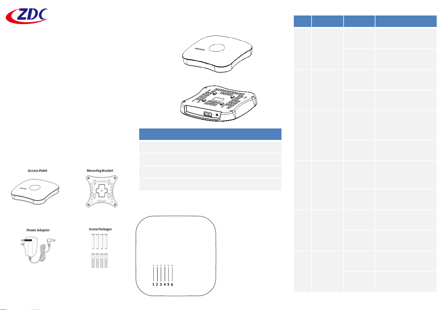
HARDWARE OVERVIEW
Front View
No LED State Description
1 Power On
(Green)
Power on, device
ready
Indoor Access Point
Quick Setup Guide
This Quick Setup Guide provides step-bystep instructions on how to set up your AC1027-I indoor Access Point. After
completing the steps described in this
Guide, you will be able to place the AP at
your site and provide wireless network
access to users.
PACKAGE CONTENTS
Rear View
No. Item
1 LAN2 port
2 PoE/LAN1 port
3 DC-Jack
4 Reset button
LED definitions
1. Power
2. System
3. LAN1
4. LAN2
5. WLAN1
6. WLAN2
Off
(Green)
2 System On
(Green)
Off
(Green)
3 LAN1
(PoE)
4 LAN2 On
5 WLAN 1
(2.4G)
6 WLAN2
(5G)
On
(Green)
Off
(Green)
(Green)
Off
(Green)
Blinking
(Green)
Off Wireless is
Blinking
(Green)
Off Wireless is
No power to AP
System on, device
ready
No connection
Network
connection is
established
Network disabled
or no link
Network
connection is
established
Network disabled
or no link
Ongoing wireless
data transmission
disabled or no link
Ongoing wireless
data transmission
disabled or no link
Page 2

SETUP REQUIREMENTS
Before installing your AC-1027-I access point, be
sure that you have the following:
• A computer running Windows 7, Vista, or XP
• A CAT5 UTP cable of required length
• Power adapter came with the package.
STEP 1: POWER ON THE AP
The AP supports both AC power and PoE. For
instructions on completing the power connection
that you need to make, refer to the
procedures below:
Use AC Power
1. Using the shipped power adapter to
connect to the AC/DC jack on the rear side
of the AP.
2. Connect the power plug to a wall socket.
Use Power Over Ethernet
The Wireless Access Point supports power
over the Ethernet port. The Wireless
Access Point automatically turns on as
soon as it is connected to a PoE switch.
1. Insert one end of an Ethernet cable to the
LAN 1/POE port on the Access Point.
2. Insert the other end to the LAN port on a
PoE switch.
3. Perform a spot-check to verify if the PWR
LED is lit to make sure the AP is powered
up successfully.
STEP 2: CONNECT THE AP TO YOUR
PC
1. Insert one end of an Ethernet cable to the
LAN 1 port on the Access Point.
2. Insert the other end to the assigned LAN
port on your PC as figured above.
3. From your computer, go to Start > Settings >
Network Connections or Start > Control
Panel > Network Connections.
4. When the Network Connections window
appears, right-click the icon for Local Area
Connection, and then click select Properties.
5. Select Internet Protocol (TCP/IP) from the
scrolling list, and then click Properties.
6. Select Use the following IP address option
(if it is not already selected), and then make
the following entries:
• IP address: Any address in the 192.168.1.x
network
• Subnet mask: 255.255.255.0
7. Click OK to save your changes, and exit the
dialog box.
STEP 3: LOG INTO THE AP
1. On your PC, open a Web browser window.
2. In the browser, type https://192.168.1.1 and
press <Enter> to connect to the AP.
3. When a security alert dialog box appears,
click OK/Yes to proceed.
4. When the login page appears, enter the
following:
• Username: admin
• Password: password
5. Click Login.
STEP 4: CONFIGURE THE AP
The procedure for completing the Access Point’s
essential configuration depends on whether you
want it to be managed by either AP controller or
to operate as a standalone Access Point. Refer to
the section that is relevant to your deployment:
• Configuring for Management by AP Controller
• Configuring for Standalone Operation
Configuring for Management by AP
Controller
To configure the Access Point to be managed
by the AP controller, you must ensure that
the APs will be able to locate and connect to
the controller when powered on. Specifically,
you need to ensure the following.
Page 3
• When connected to the network, each AP
is assigned a valid IP address
• APs are able to locate and connect the
controller
The Access Point requires a unique IP address
(fixed IP or DHCP IP) on a network that has
connectivity to a controller. The DHCP server
can be an existing network server or a ZDC
controller configured as a DHCP server.
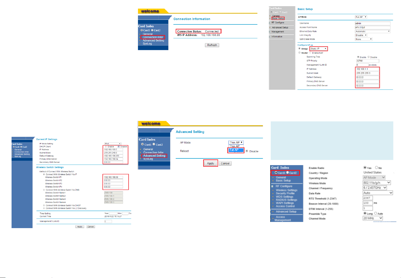
1. Once login, first assign a fixed IP address
or a DHCP IP to the AP under Current IP
Setting. Under Wireless Switch Setting,
select Connect With Wireless Switch Via
IP and input the IP address of the AP
access controller. Click Apply to take
effect.
Configuring for Standalone Operation
Before configuring fat AP Basic settings, make
sure that AP mode is set to Fat AP.
1. If currently in Thin AP Mode: On the main
menu on the left, click Advanced Setting.
Select Fat AP from the drop-down list. Click
Apply to take effect.
3. Go to RF Configure > Wireless Settings. (For
dual band 5G setting, select Card 2 first then
go to RF Configure > Wireless Settings.)
Note:
For dual band APs, the two radios (2.4GHz and
5GHz) need to be configured separately on the
Web interface. The rest of the configuration
procedures are the same as for 2.4G and 5G radio.
2. On the main menu on the left, go to
Connection Info to check the connection
status with the AP controller. If the tunnel
has been made successfully, the connection
status will show: Connected.
2. On the main menu on the left, click Basic
Setup. In the Basic Setup page, go to the
section Configure AP as. If you want to assign
a fixed IP address, select Static IP. Enter the
parameters in the following fields: IP Address,
Subnet Mask, Default Gateway, Primary DNS
Server, and Secondary DNS Server. If you want
the wireless AP to obtain the address from the
DHCP Server automatically, select DHCP Client.
Click Apply.
These are the essential wireless settings that will
enable wireless devices on the network to
associate with the Access Point.
Page 4

4. Configure the common RF setting as Channel.
5. Click Apply to save the changes.
6. Go to RF Configure > Security Profile.
7. Click one of the profiles #, tick the Enable
box and press Edit.
10. In Network Authentication, select the
desire authentication method and then
enter the encryption phrase accordingly.
2. Move the AP to its permanent location
(accessible to both power source and
network connections).
Note:
Some placement guidelines you should follow to
maximize performance and coverage.
The AC-1027-I Access Point ‘s ideal orientation is
pole mount (e.g street light pole) with its dome
pointing straight down. All APs should be
mounted as high and as visible as possible. Try
to avoid any obstructions, especially those in
close proximity to the AP . The signal strength it
will receive depends largely on its position, so
make sure that sufficient survey has been made
to determine the best placement for maximum
range, coverage, and network performance
before installing. Nevertheless, as RF can be
affected by many variables, your actual
performance may vary from the planned design.
8. Clear the Security Profile Name and
Wireless Network Name (SSID) box, and
then type a unique name that you desire
to call this wireless network. This will
help users identify this wireless network
in their wireless network connection.
9. Adjust the maximum connected users if
necessary.
11. Click Apply to save the changes.
12. Click Logout to exit the Web interface.
STEP 4: VERIFY THE CONNECTION
1. Connect the AP to your network.
2. Use any wireless-enabled computer or
mobile device to search for and select the
wireless network you’ve previously
configured.
3. If you can connect, open a browser and link
to any public website.
STEP 5: INSTALL THE AP
1. Disconnect the AP’s power adapter from the
power outlet (or disconnect the PoE cable).
The AC-1027-I can be mounted to a hard
ceiling or suspended ceiling using the supplied
mounting bracket and screws.
Mounting Bracket
Screw Packages
Page 5

MOUNTING BELOW A SUSPENDED
CEILING
1. Identify the location where you intend to
mount the access point.
2. Raise the selected ceiling tile on both
sides of the channel to remove the tile.
3. Use the mounting bracket as a template
to mark the locations of the mounting
holes on the tile.
4. Use a drill to drill a pilot hole at the
mounting hole locations you marked.
5. Position the mounting bracket holes (with
indents up) over the pilot holes.
6. Insert a fastener into each mounting hole
and tighten.
7. If necessary, drill or cut a cable access hole
in the ceiling tile large enough for the
Ethernet cables. Pull the cable through the
access hole until you have about 1 foot of
cable protruding from the hole.
8. Connect the Ethernet cable to the access
point.
9. Align the access point hook over the
keyhole mounting slots on the mounting
bracket (see up arrow in the below figure).
If you created a hole for the cable, make
sure the access point is positioned so that
the cable reach their respective port.
10. Gently slide the access point onto the
mounting bracket until it clicks into place
(See left arrow in the below figure).
Reinstall the ceiling tile.
MOUNTING ON A HARD CEILING
This procedure describes the steps required to
mount the access point on a hard ceiling using
the mounting bracket.
1. Use the mounting bracket as a template to
mark the locations of the mounting holes
on the ceiling.
2. Use a drill to drill a pilot hole at the
mounting hole locations you marked and
insert the plastic anchors.
3. Position the mounting bracket mounting
holes (with indents up) over the pilot holes.
4. Insert a fastener into each mounting hole
and tighten.
5. Connect the Ethernet and power cables to
the access point.
6. Align the access point hook over the
keyhole mounting slots on the mounting
bracket. If you created a hole for the cable,
make sure the access point is positioned
so that the cable reach their respective
port.
7. Gently slide the access point onto the
mounting bracket until it clicks into place.
Page 6

STEP 6: POWER AND CONNECT
(2) 10/100/1000 Ethernet
48V, 0.5A
PSK,
1. Insert the other end to the LAN/PoE port
on the AC-1027-I.
2. Insert the other end of an Ethernet cable
to the P+D/OUT port on the PoE injector.
Make sure the Cat5e cable (outdoorrated) from the Access Point is long
enough to reach the PoE injector.
3. Insert one end of an Ethernet cable to
the DATA/IN port on the PoE injector as
figured above.
4. Connect the other end of the Ethernet
cable to the switch or a PC.
5. Connect a power cord to the PoE injector.
6. Connect the power plug to a wall socket.
7. Perform a spot-check to verify if the
PWR and LAN LED are lit to make sure the
AP is operating normally
Specifications
Specifications
Dimensions 250 x 220 x 55 mm
Weight 800 g
Networking Interface
Buttons (1) Reset to Defaults
Antennas
Wi-Fi Standards 802.11 a/b/g/n/ac
Power Method PoE 802.3at
Power Supply
Max. Power
Consumption
(2) 2GHz 5dBi Antennas
(3) 5GHz 5dBi Antennas
PoE
DC Jack 12V, 1.5A
Ports
8 W
STEP 7: VERIFY THE CONNECTION
1. Use any wireless-enabled computer or
mobile device to search for and select the
wireless network you’ve previously
configured.
2. If you can connect, open a browser and
link to any public Web site.
3. From PC’s Network - Wireless Properties
page. Observe the wireless signal quality
and speed.
Copyright © 2016 Z-Com, Inc. All rights reserved.
ZWA is trademark of Z-Com, Inc. All other company and
product names mentioned in the documentation are held to
be trademarked (and registered) by the primary holders.
BSSID Up to 8 per Radio
WEP, WPA-
Wireless Security
(WPA/WPA2, TKIP/AES)
Certifications CE, FCC, IC
Mounting Wall/Ceiling(Kits Included)
Operating Temperature 0 to 55℃
Operating Humidity 10 to 90 % Non-condensing
WPA-Enterprise
Page 7

Federal Communications Commission
FCC Caution: Changes or modifications not expressly approved by the party responsible for compliance could void the user's authority to
operate this equipment.
Note: This equipment has been tested and found to comply with the limits for a Class A digital device, pursuant to part 15 of the FCC Rules.
These limits are designed to provide reasonable protection against harmful interference when the equipment is operated in a commercial
environment. This equipment generates, uses, and can radiate radio frequency energy and, if not installed and used in accordance with the
instruction manual, may cause harmful interference to radio communications. Operation of this equipment in a residential area is likely to
cause harmful interference in which case the user will be required to correct the interference at his own expense.
Data transmission is always initiated by software, which is the passed down through the MAC, through the digital and analog baseband, and
finally to the RF chip. Several special packets are initiated by the MAC. These are the only ways the digital baseband portion will turn on the
RF transmitter, which it then turns off at the end of the packet. Therefore, the transmitter will be on only while one of the aforementioned
packets is being transmitted. In other words, this device automatically discontinue transmission in case of either absence of information to
transmit or operational failure. Frequency Tolerance: 20 ppm
This transmitter must not be co-located or operated in conjunction with any other antenna or transmitter.
This equipment complies with FCC/IC radiation exposure limits set forth for an uncontrolled environment and meets the FCC radio
frequency (RF) Exposure Guidelines and RSS-102 of the IC radio frequency (RF) Exposure rules. This equipment should be installed and
operated keeping the radiator at least 20cm or more away from person’s body.
End Product Labeling this transmitter module is authorized only for use in device where the antenna may be installed such that 20 cm may
be maintained between the antenna and users.
15.19
This device complies with Part 15 of the FCC Rules.
Operation is subject to the following two conditions:
1) this device may not cause harmful interference and
2) this device must accept any interference received, including interference that may cause undesired operation of the device
Copyright © 2016 Z-Com, Inc. All rights reserved.
ZDC is trademark of Z-Com, Inc. All other company and product names mentioned in the documentation are held to be trademarked (and registered) by the primary holders.
 Loading...