

Page 1
AC-1025D Dual SIM
LTE-Fi Access Point
Quick Installation Guide
This Quick Setup Guide provides step-by-step
instructions on how to set up your LTE-Fi Access
Point. After completing the steps described in
this guide, you will be able to place the AP at
your site and provide wireless network access
to users.
PACKAGE CONTENTS
LTE-Fi Access Point Power Cable
Mounting Kit Security Plate & Cable Cover
Screw Kit LTE & GPS Antennas
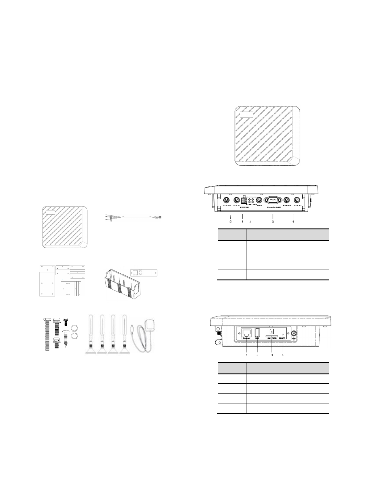
HARDWARE OVERVIEW
3D View
Bottom View
No Item
1 Power
2 LED Indicators
3 Console Port
4 and 5 LTE Antennas
Side View
(Right side)-SIM 1 support Band3/8
No Item
1 RF-45 Ethernet Port
2 USB slot
3 SIM Card Slot
4 Reset Pinhole
(Left side)-SIM 2 support Band3/28
Page 2
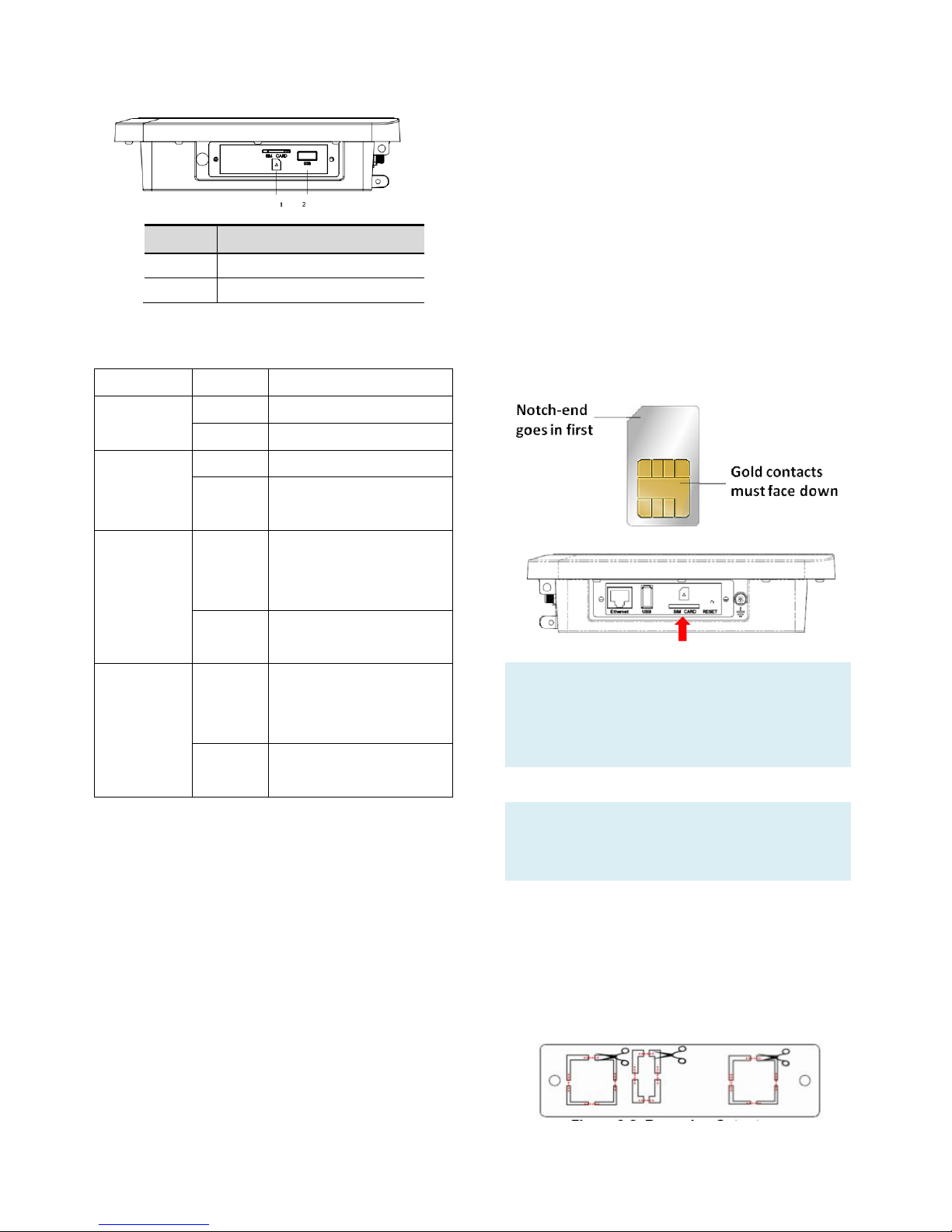
No Item
1 SIM Card Slot
2 USB slot
LED Indication
Activity Description
Power/Test
Green Power on
Off Power off
Wireless
LAN
Off Wi-Fi off
Blink
Green
Wi-Fi WLAN Network
activity is occurring
LTE A
Off Can not find 3G/4G
mobile communication
network
Green Connect 3G/4G mobile
communication network
LTE B
Off Can not find 3G/4G
mobile communication
network
Green Connect 3G/4G mobile
communication network
SETUP REQUIREMENTS
Before installing your LTE-Fi access point, be
sure that you have the following:
• A computer running Windows 7, Vista, or XP
• A CAT5 UTP cable of required length
• Power cable came with the package
STEP 1: INSERT AN ACTIVATED SIM
A wireless broadband data plan must be added
to your LTE-Fi AP. The SIM must be provisioned
with the carrier. Contact your carrier for details
about selecting a data plan and about the
process for provisioning your SIM.
Once you have an activated SIM (Mini SIM),
insert it into the SIM slot of LTE-Fi AP. Be sure
to insert the card with the notch-end first and
the gold contacts facing down – it will click into
place.
Note: Before plugging the SIM card into the
LTE-Fi AP, you need to disable PIN verification in
advance. This operation can be done with a
phone.
CAUTION: The SIM card slot does not support
hot swap, please DO NOT plug out or change
SIM card when the Access Point is powered up.
To protect the SIM card from theft, you can
attach the anti-theft security plate to cover the
SIM card slot:
1. Clear cutouts on the security plate marked
in red.
Page 3
2. Attach the security plate to the LTE-Fi AP
with the 4 circle mark points marked in red
below facing to the SIM card/USB/Ethernet
interfaces. The Ethernet and USB access
holes on the security plate must be aligned
with the Ethernet and USB slots on the
LTE-Fi AP.
3. Secure the plate with two screws (without
washer) using a torx screwdriver.
The below figure shows the SIM card installed
and the SIM access plate closed.
4. Repeat the above steps to do the second
SIM slot.
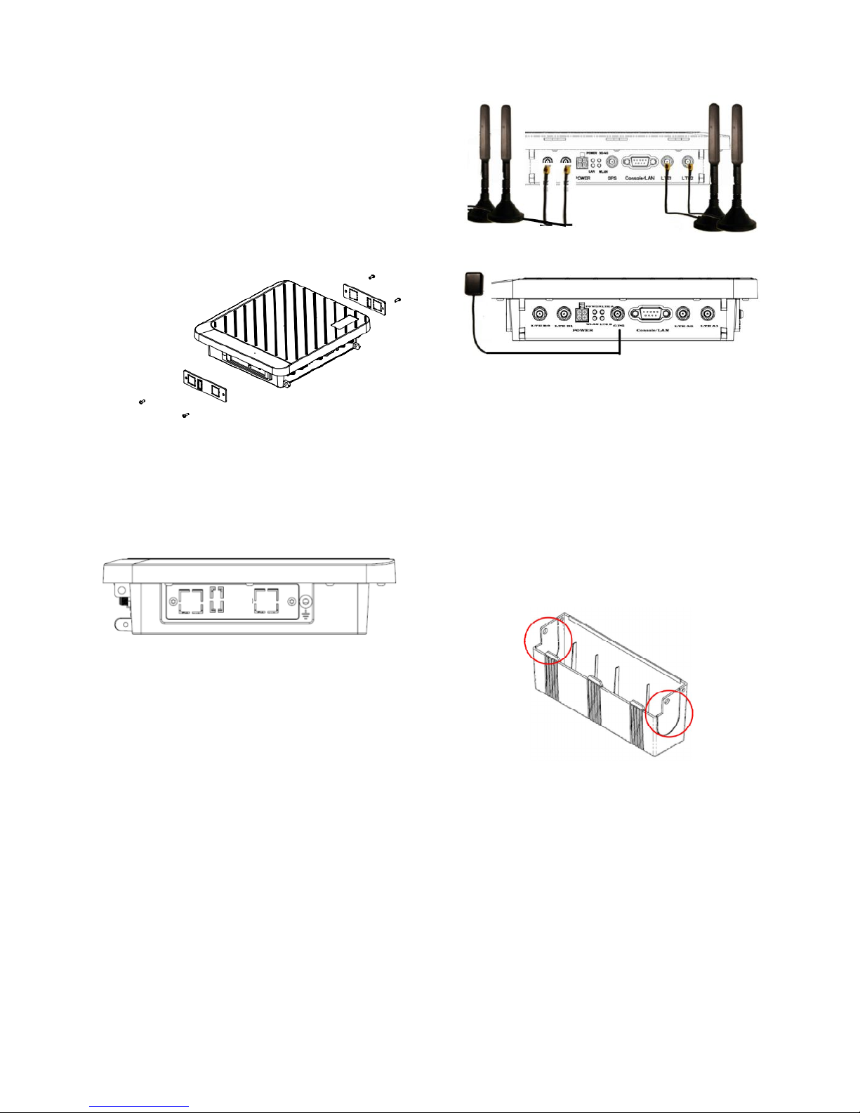
STEP 2: CONNECT THE ANTENNAS
1. Attach the four included LTE antennas on
the connectors labeled
LTEA1/LTEA2/LTEB1/LTEB2 respectively on
the LTE-Fi AP and one GPS antenna to the
SMA connector on the LTE-Fi AP.
LTE Antenna Installation
GPS Antenna Installation
2. Position the antennas so they suit your
deployment scenario.
STEP 3: ATTACH THE CABLE COVER
The LTE-Fi AP comes with a plastic cable cover
to hide AP’s power and antenna connectors to
prevent removal of power and antenna cables.
1. Clear cutouts on both sides of cable cover
marked in red.
2. Route the antenna and power cables out of
the access slots on either side of cover.
3. Align the tabs on the cable cover with the
slots on the bottom of the LTE-Fi AP and
slide into place.
Page 4

4. Secure the cable cover with the M3xL8
screws (with washer).
STEP 4: MOUNT THE ACCESS POINT
The LTE-Fi AP can be mounted to a pole or any
flat surface on the vehicle using the supplied
mounting brackets and screws.
Screw Set
A. M5xL40 screw x1
B. M5xL20 screws x4
C. M3xL8 screw x6
w/ washer: for cable cover
w/o washer: for securing SIM card
D. M4xL20 screws x2
E. M5xL10 screws x9
F. Hexagonal nuts x8
Brackets
MOUNTING ON A POLE
1. Select a pole where the power is available
nearby to mount the access point. You can
attach the access point to any pole from 29
to 33 mm in diameter.
2. The pole mount kit contains several parts
that you must assemble prior to mounting
on a pole. First you need to attach the
bracket ① on the LTE-Fi AP using the four
M5xL10 screws.
3. Attach bracket④ on the bracket① using
three M5xL10 screws and nuts.
4. Attach the mounting bracket with LTE-Fi AP
on the pole using bracket ③ and four
M5xL20 bolts with nuts.
5. To fix the AP on the hole better, it is highly
recommended to drill a hole on the pole to
tighten the bracket. After the bracket is
fixed on the pole, use the holes circled in
red on the bracket③ and bracket④ to
mark the location where the hole will be
drilled on the pole. Make sure the holes
are aligned.
Page 5

6. Use a center punch where it is practical to
dimple the pole you are going to drill.
7. Try drilling a pilot hole with a small
diameter bit. If you are successful in drilling
the hole without the bit slipping, and are
satisfied with the results, step up to larger
bits until you have a sufficiently large hole
for your purpose.
8. Insert the M5xL40 screw into the drilled
hole and use the nut to tighten to secure
the bracket to pole. If there
is no significant movement, you are
probably tight enough. If the M5xL40
screw is not long enough to secure the
bracket, use other longer screw instead.
Pole Mount _Vertical
Pole Mount _Horizontal
MOUNTING ON A FLAT SURFACE
1. Attach the bracket ① on the LTE-Fi AP
using the four M5xL10 screws.
2. Mark two screw holes with bracket② on
the place you have selected where the
power is available nearby on the vehicle.
3. Use a drill to create two holes on the two
markings you created in the previous step.
4. Attach bracket② on the bracket① using
three M5xL10 screws and nuts.
5. Attach the cable cover to the junction box
using the screws from the removed cover
plate.
6. Insert two M4xL20 screws into the
installation holes and tighten up.
Flat Surface Mount _Bottom
Flat Surface Mount _Top
Page 6

STEP 5: CONNECT THE POWER
SOURCE
CAUTION:
Please connect to the correct color of cable to
each position, or the wrong connection will
damage your AP.
The standard power supply of the LTE-Fi AP is
12V-24V DC. Please use the factory supplied
power cable. Refer the below wiring diagram
to connect each wire to power source of the
vehicle.
Power Cord
Wire Colors Description
Red Connect to battery positive +
Black
Connect to battery negative
- Orange
Connect to ACC
ignition
Brown
Connect to relay control line
Power Wiring Diagram
When you power cord is connected the LTE-Fi
AP and the power source, watch for the power
LED to illuminate.
STEP 6: SET UP THE AP
CONNECT THE AP TO YOUR PC
1. Connect one end of an RJ-45 cable to an
Ethernet port on your computer.
2. Connect the other end to the LAN port on
Page 7

the wireless AP.
3. From your computer, go to Start > Settings >
Network Connections or Start > Control
Panel > Network Connections.
4. When the Network Connections window
appears, right-click the icon for Local Area
Connection, and then click select Properties.
5. Select Internet Protocol (TCP/IP) from the
scrolling list, and then click Properties.
6. Select Use the following IP address option (if
it is not already selected), and then make
the following entries:
• IP address: Any address in the 192.168.1.x
network
• Subnet mask: 255.255.255.0
7. Click OK to save your changes, and exit the
dialog box.
LOG INTO THE AP
1. On your PC, open a Web browser window.
2. In the browser, type https://192.168.1.1 and
press <Enter> to connect to the AP.
3. When a security alert dialog box appears,
click OK/Yes to proceed.
4. When the login page appears, enter the
following:
• Username: admin
• Password: password
5. Click Login.
CONFIGURE THE AP
The procedure for completing the Access
Point’s essential configuration depends on
whether you want it to be managed by either
AP controller or to operate as a standalone
Access Point. Refer to the section that is
relevant to your deployment:
• Configuring for Management by AP
Controller
• Configuring for Management by zCloud
• Configuring for Standalone Operation
Configuring for Management by AP Controller
To configure the Access Point to be managed by
the AP controller, you must ensure that the APs
will be able to locate and connect to the
controller when powered on. Specifically, you
need to ensure the following.
When connected to the network, each AP is
assigned a valid IP address
APs are able to locate and connect the
controller.
The Access Point requires a unique IP address
(fixed IP or DHCP IP) on a network that has
connectivity to a controller. The DHCP server
can be an existing network server or a ZDC
controller configured as a DHCP server.
1. Once login, first assign a fixed IP address or
a DHCP IP to the AP under Current IP
Setting. Under Wireless Switch Setting,
select Connect With Wireless Switch Via IP
and input the IP address of the AP access
controller. Click Apply to take effect.
2. On the main menu on the left, go to
Connection Info to check the connection
status with the AP controller. If the tunnel
has been made successfully, the connection
status will show: Connected.
Page 8

3. To check 3G/4G connection status, go to LTE
Information.
Configuring for Management by zCloud
Before configuring the LTE-Fi AP to be managed
by zCloud, make sure that AP mode is set to Fat
AP.
1. If currently in Thin AP Mode: On the main
menu on the left, click Advanced Setting.
Select Fat AP from the drop-down list.
Click Apply to take effect.
2. Go to Managed By Cloud > Cloud
Management. Click Yes to enable cloud
management and enter zCoud IP or DNS
address provided by the supplier. Click
Apply. If the connection has been made
successfully, the Cloud Connectivity Status
will show: Connected.
3. To check 3G/4G connection status, go to LTE
Information.
Configuring for Standalone Operation
Before configuring fat AP Basic settings, make
sure that AP mode is set to Fat AP.
1. If currently in Thin AP Mode: On the main
menu on the left, click Advanced Setting.
Select Fat AP from the drop-down list.
Click Apply to take effect.
2. On the main menu on the left, click Basic
Setup. In the Basic Setup page, go to LAN
Port and assign a fixed IP address to the LTE
Fi AP. Click Apply.
3. Go to RF Configure > Wireless Settings.
(For dual band 5G setting, select Card 2 first
then go to RF Configure > Wireless
Page 9

Settings.)
Note:
For dual band APs, the two radios (2.4GHz and
5GHz) need to be configured separately on the
Web interface. The rest of the configuration
procedures are the same as for 2.4G and 5G
radio.
4. These are the essential wireless settings
that will enable wireless devices on the
network to associate with the Access Point.
5. Configure the common RF setting as such
Country/Region domain and Channel.
Click Apply to save the changes.
6. Go to RF Configure > Security Profile. Click
one of the profiles #, tick the Enable box
and press Edit.
7. Clear the Security Profile Name and
Wireless Network Name (SSID) box, and
then type a unique name that you desire to
call this wireless network. This will help
users identify this wireless network in their
wireless network connection. Adjust the
maximum connected users if necessary.
8. In Network Authentication, select the
desire authentication method and then
enter the encryption phrase accordingly.
9. Click Apply to save the changes.
10. Click Logout to exit the Web interface.
STEP 7: VERIFY THE CONNECTION
1. To check 3G/4G connection status, go to LTE
Information.
2. Connect the AP to your network.
3. Use any wireless-enabled computer or
mobile device to search for and select the
wireless network you’ve previously
configured.
4. If you can connect, open a browser and link
to any public website.
Copyright © 2016 Z-Com, Inc. All rights reserved.
ZWA is trademark of Z-Com, Inc. All other company and product
names mentioned in the documentation are held to be trademarked
(and registered) by the primary holders.
 Loading...