

Page 1
000
Page 2

FCC Information
This device complies with Part 15 of the FCC Rules. Operation is subject to the
following two conditions: (1) this device may not cause harmful interference, and (2)
this device must accept any interference received; including interference that may
cause undesired operation.
Federal Communications Commission (FCC) Statement
This Equipment has been tested and found to comply with the limits for a Class B and
C digital device, pursuant to Part 15 of the FCC rules. These limits are designed to
provide reasonable protection against harmful interference in a residential installation.
This equipment generates, uses and can radiate radio frequency energy and, if not
installed and used in accordance with the instructions, may cause harmful
interference to radio communications. However, there is no guarantee that
interference will not occur in a particular installation. If this equipment does cause
harmful interference to radio or television reception, which can be determined by
turning the equipment off and on, the user is encouraged to try to correct the
interference by one or more of the following measures:
- Reorient or relocate the receiving antenna.
- Increase the separation between the equipment and receiver.
- Connect the equipment into an outlet on a circuit different from that to which the
receiver is connected.
- Consult the dealer or an experienced radio/TV technician for help.
FCC RF Radiation Exposure Statement:
1. This Transmitter must not be co-located or operating in conjunction with any other
antenna or transmitter.
2. This equipment complies with FCC RF radiation exposure limits set forth for an
uncontrolled environment. This equipment should be installed and operated with a
minimum distance of 20 centimeters between the radiator and your body.
1
Page 3

CONTENTS
Before You Start
You must have the following items................................................3
Checklist ...................................................................................3
Character ..................................................................................3
Hardware Installation
Connect the station adapter to your Ethernet-enabled device............4
Mechanical Description................................................................5
Connecting One Ethernet-Device (as Station) .................................6
Connecting Multiple Ethernet-Devices (as Bridge) ...........................6
Configuring Your Adapter with a web browser
Information ...............................................................................9
Configuration.............................................................................10
TCP/IP ......................................................................................16
Statistics...................................................................................17
Firmware Upgrade ......................................................................18
Appendix...................................................................................19
Limited Warranty
2
Page 4

You must have the following items
An Ethernet-enabled device, such as a game console, PC, or network printer
will connect to the station adapter.
Checklist
If you discover damaged or missing items, please contact your local reseller.
802.11g Wireless LAN Station Adapter x 1
Power Adapter x 1
CDx1
User’s Manual x 1
Character
Ethernet Connector: 10/100BaseTR-45 LAN port with Auto-MDIX
Power Supply: DC 5V/2A
Configuration: WEB-Based utility
Antenna: One External dipole antenna, gain 2dBi, with diversity function
Operation: Station Adapter
Supported Operating systems: Win98SE/ME/2000/XP/Mac OS
Security: WEP/WPA with PSK
3
Page 5
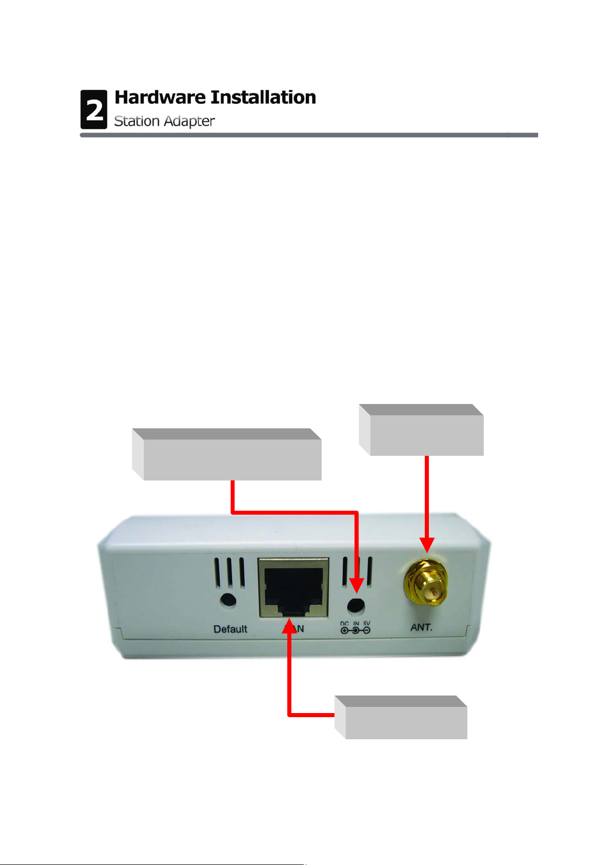
Connect the station adapter to your
Ethernet-enabled device
A. Connect the power adapter to the 802.11g Wireless LAN Station
Adapter.
B. Connect one end of an Ethernet cable to the 802.11g Wireless LAN
Station Adapter and connect the other end to the Ethernet LAN port
located on the device (e.g., a gaming console, laptop, desktop computer,
or network printer).
C. Combine the antenna with the station adapter to wirelessly connect to
the 802.11g networks.
A. Power Ada pter
C. Ant e nna
B. LAN Po r t
4
Page 6
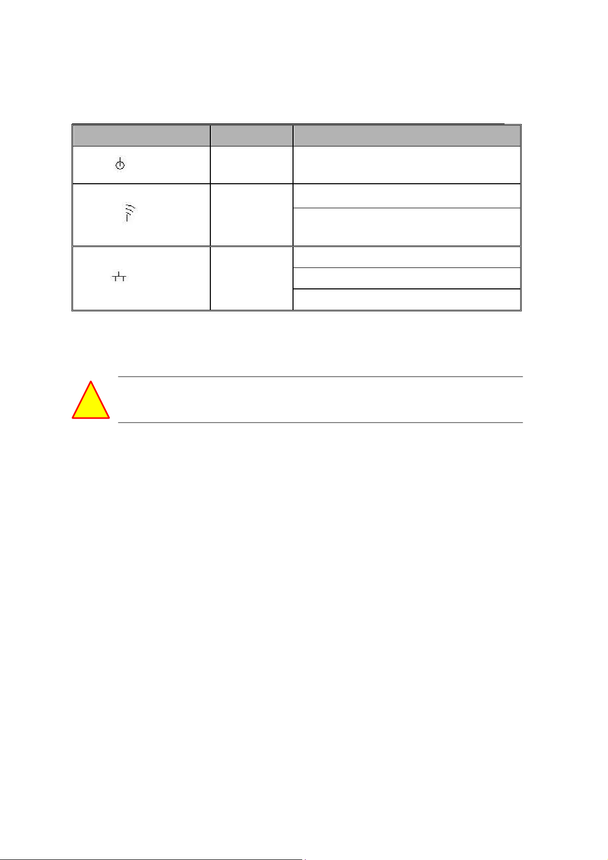
Mechanical Description
The following table provides an overview of each LED activity:
LED Definition Activity Description
PWR
WLAN
Power Socket
Using the power adapter supplied with the Wireless LAN Station will prevent
damage to the station adapter and personal injury.
We cannot assume the responsibility for the damage from
using with the other power adapter supplier.
LAN Ports
Connect the Wireless LAN Station Adapter to a hub or a PC with Ethernet
cable. Please note that, use the Ethernet cable when you directly connect
the Wireless LAN Station Adapter to a PC.
Green Power enabled
Off: No Wireless LAN traffic activity
Green
Green
On: Associated to the Wireless AP
and Wireless LAN traffic activity.
Off: No Ethernet traffic activity
Flashing: Wired LAN traffic activityLAN
On: Connect to the Ethernet.
Antenna
Notice that you connect tightly the External dipole antenna on the antenna
connector of your station adapter. A loosen antenna will reduce the radiant
energy or even lose it. In order to improve the RF signal radiation of your
antenna, proper antenna placement is necessary. We recommend you
mount the antenna attached to access point in the position that can be best
covered by its BSS. Try to place the antenna as high as possible to increase
the coverage area. If you have further question, please contact your wireless
network administrator.
Default
Press the “default” button for about 3 seconds until the LEDs go off. This
action will restore to the factory default settings of the wireless station
adapter and enable you to configure the station adapter via web again.
Besides, this is also used when you forget the password.
5
Page 7
Connecting One Ethernet-Device (as Station)
The station can be implemented on allowing only one client to access the
wireless network using MAC clone functionality. To connect with one client,
follow these steps:
1. Connect one end of the Ethernet Cable to the Station Adapter and the
other to the Ethernet-enabled device.
2. Connect the power adapter to station adapter’s power jack. The power
and the Ethernet status should light up.
3. Turn on the Ethernet-enabled device. When the station adapter is
associated to the Wireless AP and Wireless LAN traffic activity, you will
see the wireless LAN status lights up.
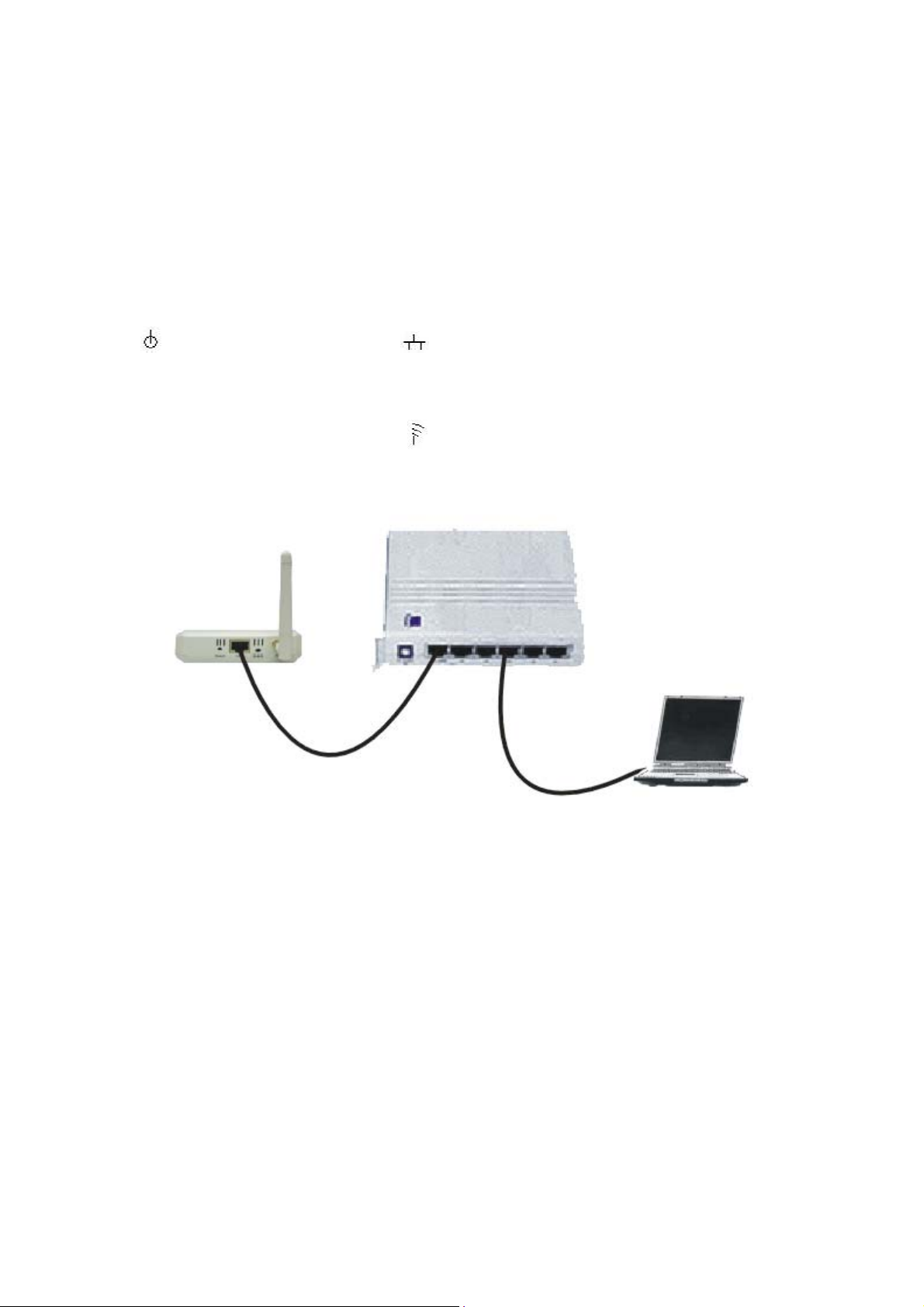
Connecting Multiple Ethernet-Devices (as Bridge)
The station can be implemented on allowing multi-clients to join a network.
When connecting to the wireless station adapter, the client who first begins
to send packet can associate with the access point that responds to the first
client’s request for connection based on MAC clone functionality. And the
others use the MAC address of the first client to join a wireless network. To
connect with multi-clients, follow these steps:
1. Connect one end of the Ethernet Cable to the Station Adapter and the
other to the hub.
2. Connect the Ethernet Cable between Ethernet-enable devices and the
hub.
6
Page 8

3. Connect the power adapter to station adapter’s power jack. The power
and the Ethernet light should light up.
4. Connect the power adapter to the hub.
5. Turn on all Ethernet-enable devices. When the station is associated to the
Wireless AP and Wireless LAN traffic activity, you will see the wireless LAN
status lights up.
Note1: A hub could connect with up to 8 Ethernet-devices. However, it
would reduce the transmission rate if connected with too many units. (The
more units to connect with will produce less transmission rate.)
Note2: If all of your clients do not support TCP/IP protocol, only the first
client can connect to the wireless station adapter.
7
Page 9

How to access the web-browser configuration utility? Please do the
following:
1. Connect your computer to the wireless station adapter either through
wireless or wired connection. Please set a fixed IP address (refer to
Appendix), within the range of 192.168.0.X (X can’t be 10), to your
computer.
2. Activate your browser, then type this Station Adapter’s address (e.g.
http://192.168.0.10), in the Location (for IE) or Address field and press
Enter.
3. Key in the system password (the default setting is “default”) and click on
the “Login” button. You will see the main page.
8
Page 10

The main window provides 5 items for you to monitor and configure the
Wireless LAN Access Point: Information, Configuration, TCP/IP,
Statistics and Firmware Upgrade.
Information
This item shows the current information on the 802.11g Wireless LAN
Station Adapter such as MAC Address, Firmware Version as well as Boot
Version.
9
Page 11

Configuration
General:
Station Adapter Name: In this field, you may enter any name. This will
enable you to manage your Station Adapter more easily if you have
multiple station adapters on the network. Besides, Station Adapter
Name can be used to prevent you from forgetting an IP Address and fail
to access the website. Try to type the nickname you like to identify the
website, then press the button of “Apply” to reboot. Whenever you want
to get back to the website again, just type the name you login.
ESSID: The ESSID is a unique ID used by Access Points and Stations to
identify a wireless LAN. Wireless clients associating to any Access Point
must have the same ESSID. The default ESSID is ANY. The ESSID can
have up to 32 characters.
Network Type: There are 2 network types for the wireless station
adapter to operate. If you need to access company network or Internet
via Access Point, select “Infrastructure”. To set up a group of wireless
stations for files and printer sharing, select “Ad-Hoc” (without Access
Point). For Ad-Hoc operation, the same ESSID is required to set for the
wireless stations.
Channel: Select a clear and available channel as an operational channel
for your wireless station adapter when it performs as Ad-Hoc mode.
10
Page 12

Mode: There are three different wireless modes to operate, “B Only
Mode”, “G Only Mode”, and “B/G Mixed Mode”. In B/G Mixed Mode, the
wireless station adapter is compatible with a mix of both 802.11g and
802.11b clients. You will see that the factory-set default “B/G Mixed Mod”
will prove the most efficient. B Only Mode is compatible with 802.11b
clients only. This mode can be used only if you do not allow any 802.11g
clients to join a network. G Only Mode is compatible with 802.11g clients
only. This mode can be used only if you do not allow any 802.11b clients
to access to the network. To switch the mode, select the desired mode
form the pull-down menu next to “Mode”.
Rate: The wireless station adapter provides various data rate options for
you to choose. Data rates options include Auto, 1, 2, 5.5, 11, 6, 9, 12,
18, 24, 36, 48 and 54. The default setting is Auto.
Country/Region: Allows you to select country domain in case there is
any chances that you would use wireless network in other countries.
There are a total of 11 countries for you to select. They are Africa, Asia,
Australia, Canada, Europe, France, Israel, Japan, Mexico, South America,
and USA. Note that if your AP and station adapter are in different
standards, please use the “Country/Region” item to switch the
standards of the station adapter (For example, if your Access Point is
America standard but your station adapter is Japanese standard, you can
pull down the “Country/Region” option to switch your station adapter
from Japanese standard to American standard.).
Password: You may change the default password by entering the new
password.
Click “Apply” if you have made any changes.
11
Page 13

WEP:
The wireless station adapter allows you to create up to 4 data encryption
keys to secure your data from being eavesdropping by unauthorized
wireless user. To enable the encryption, all devices on the network, such as
the Access Point, must share the same WEP selection – either Enable or
Disable, and they must share the same WEP key.
Disable: Allows the wireless station adapter to communicate with the
Access Point without any data encryption.
WEP40: Requires the wireless station adapter to use data encryption
with 40-bit algorithm when communicating with the Access Point.
WEP128: Allows the wireless station adapter to communicate with the
Access Point with data 128-bit encryption algorithm.
WPA: Allows the wireless station adapter to communicate with the
Access Point with a more secure data protection than the WEP. Here you
can select the WPA with PSK mode to improve the data security and
privacy during wireless transmission. The present WPA supplied with this
station adapter is used in a pre-shared key mode, which does not require
an authentication (Radius) server.
12
Page 14

For 40bit encryption you may choose:
ASCII: Enter 5 characters (case sensitive) ranging from “a-z”, “A-Z”
and “0-9” (e.g. MyKey).
Hex: Alternatively, you may enter 10 hexadecimal digits in the range
of “A-F”, “a-f” and “0-9” (e.g. 11AA22BB33).
For 128bit encryption you may choose:
ASCII: Enter 13 characters (case sensitive) ranging from “a-z”, “A-Z”
and “0-9” (e.g. MyKey12345678).
Hex: Alternatively, you may enter 26 hexadecimal digits in the range
of “A-F”, “a-f” and “0-9” (e.g. 00112233445566778899AABBCC).
After entering the WEP keys in the key field, select one key as active key.
Alternatively, you may create encryption keys automatically by using
Passphrase. From the Passphrase field, type a character string and click
Generate. As you type, the wireless station adapter will use an algorithm to
generate 4 keys automatically. Select one key from the 4 WEP keys.
Moreover, the wireless station adapter provides two types of authentication
services: Open System and Shared Key. The default authentication type is
Open System. If you require higher security for wireless access, you may
select Shared Key. Note that when Shared Key is selected, a WEP key is
required and must be the same with the key that Shared-Key-enabled AP
uses. (The authentication mode will be available soon).
13
Page 15

For WPA-PSK mode you may choose:
In the WPA-PSK field, you may enter 8-63 characters ranging from “a-z”,
“A-Z” and “0-9”.
Enter the Pre-Shared Key
14
Page 16

If you require that access to the Internet or other wireless network services
is allowed only when the pre-shared key of the station adapter matches that
of the AP.
Click the “Apply” button on the Configuration tab to make the setting take
effect.
15
Page 17

Setting:
The system item allows you to save settings to the local hard drive by
clicking “Save”. When you click the “Browse” button, you can select the
saved setting files. To click “Load”, the saved settings will be loaded back.
You also can return to Factory Default Settings by clicking “Restore”.
TCP/IP
You may assign a proper IP address to your wireless station adapter
manually. If you would like the wireless station to obtain the IP address from
the DHCP server on your network automatically, enable the DHCP client
function.
16
Page 18

Statistics
General:
This item allows you to monitor the general information of the Access Point
with which your wireless station is communicating such as Link Status,
ESSID, BSSID, Channel, Signal as well as RX/TX from Ethernet packets.
AP Browser:
By clicking the “Refresh” button, the AP Browser will reload and display
the available Access Points around the working environment. Besides
showing the BSSID of each Access Point, it also displays ESSID, Channel,
Support Rate and Capability.
17
Page 19

Firmware Upgrade
Here, you can upload the latest firmware of the wireless station adapter.
You may either enter the file name in the entry field or browse the file by
clicking the “Browse” button. Then click the “Apply” button to begin to
upgrade the process.
18
Page 20

Appendix
Follow the description if you have any problem during the installation of this
wireless station adapter.
How to assign a static IP Address in Windows XP/2000?
1. Go to “Start” > Click on “Control Panel” > Double-click on “Network
Connections” > Right-click on “Local Area Connections” > Click
“Properties”
2. Highlight “Internet Protocol (TCP/IP)” and then click “Properties”.
19
Page 21

3. Select “Use the following IP address” in the Internet Protocol
(TCP/IP) Properties window. Set your “IP address” and “subnet
mask”. (The IP Address must be within the same range as your station
adapter. The IP Address of your station adapter is 192.168.0.10. You can
assign 192.168.0.100 for your computer. No two computers can have
the same IP Address. Assign a subnet mask of (255.255.255.0.) and
then Click “OK” button.
Congratulations! You have now successfully assigned a Static IP Address in
Windows XP/2000.
20
Page 22

This Warranty constitutes the sole and exclusive remedy of any buyer or
reseller’s equipment and the sole and exclusive liability of the supplier in
connection with the products and is in lieu of all other warranties, express,
implied or statutory, including, but not limited to, any implied warranty of
merchantability of fitness for a particular use and all other obligations or
liabilities of the supplier.
In no even will the supplier or any other party or person be liable to your or
anyone else for any damages, including lost profits, lost savings or other
incidental or consequential damages, or inability to use the software
provided on the software media even if the supplier or the other party
person has been advised of the possibility of such damages.
The following are special terms applicable to your hardware warranty as well
as services you may use during part of the warranty period. Your formal
Warranty Statement, including the warranty applicable to our Wireless LAN
products, appears in the Quick Installation Guide that accompanies your
products.
Duration of Hardware Warranty: One Year
Replacement, Repair or Refund Procedure for Hardware:
If your unit needs a repair or replacement, return it to your
dealer/distributor in its original packaging. When returning a defective
product for Warranty, always include the following documents:
The Warranty Repair Card
A copy of the invoice/proof of purchase, and
The RMA Report Form (To receive a Return Materials Authorization form
(RMA), please contact the party from whom you purchased the product).
Upon proof-of-purchase we shall, at its option, repair or replace the
defective item at no cost to the buyer.
This warranty is contingent upon proper use in the application for which the
products are intended and does not cover products which have been
modified without the reseller’s approval or which have been subjected to
unusual physical or electrical demands or damaged in any way.
21
Page 23

Please complete the information below and include it along with
your products.
Name:
Title:
Company:
Tele p h o ne:
Fax:
Email:
City/State/Zip code:
Country:
Product Name:
Serial Number:
MAC Address:
Invoice Date:
Product Description:
If you have any further questions, please contact your local authorized
reseller for support.
22
 Loading...