

Page 1
7F-2, 9, Prosperity 1st Rd.,
A
Science-Based Industrial Par k, Hsinchu, Taiwan
Tel: +886-3-577-7364 Fax: +886-3-577-3359
Z-Com, Inc.
Website: http:/// www.zcom.com.tw
Email: info@ zcom.com.tw
XI-325/B Quick Installation Guide
I. Network Configuration
XI-325/B is an IEEE802.11/802.11b-compliant PCMCIA Type II DSSS wireless LAN PC card.
It fully supports wireless networking under Windows 95/98, and NT 4.0.
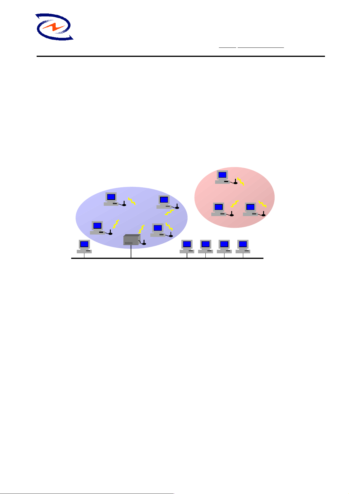
XI-325/B can be operated in Ad-Hoc and Infrastructure network configurations. Ad-Hoc mode
allows XI-325/B users to join an Basic Service Set (i.e., peer-to-peer mode, without access point).
Infrastructure mode allows XI-325/B users to join a Extended Basic Service Set (i.e., connect to
access point)
Wireless Network
Ad-hoc Network
Infrastructure Network
ccess Point
Wired Network
II. Package Content
XI-325/B 11Mb PC x 1 CD-ROM or Driver and Utility Disk x 1
XI-325/B Detachable Antenna x 1 Quick Installation Guide x 1
III. XI-325/B and Utility Installation under Windows 95/98
1. Insert XI-325/B into the PCMCIA slot, then start Windows. Windows will auto-detect new
hardware and Windows Wizard will display “New Hardware Found”
2. Click on ‘Next’, then insert the corresponding driver and utility CD-ROM into the CD-ROM
drive, or the driver and utility disk into the floppy drive. Click on ‘Next’.
3. Once [Insert Win 95/98 CD-Rom into the appropriate drive, then click ‘OK’] window
appears, please follow by either inserting the Win 95/98 CD-Rom or finding the Win 95/98
source path within the appropriate drives, then click ‘OK’.
4. Click ‘Finish’ to complete the installation. Restart Win 95/98.
5. To install the XI-325/B Utility, insert the XI-325/B driver and utility disk once again, then
execute A: setup.exe.
6. Follow the on-screen instructions to complete utility installation, then afterward double-click on
1
Page 2

7F-2, 9, Prosperity 1st Rd.,
Science-Based Industrial Par k, Hsinchu, Taiwan
Tel: +886-3-577-7364 Fax: +886-3-577-3359
Z-Com, Inc.
Website: http:/// www.zcom.com.tw
Email: info@ zcom.com.tw
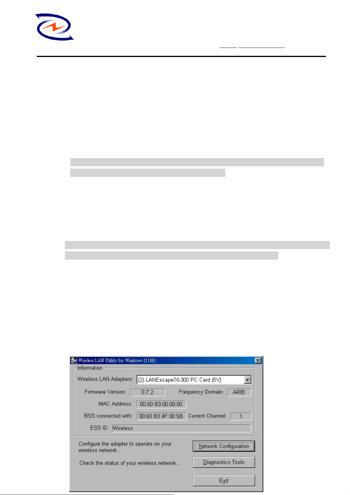
the Utility icon. Utility interface will then appear and configuration can be accomplished here.
IV. Using Utility to Set Up Ad-Hoc Network
If wireless LAN has already been set up, simply plug in XI-325/B. Otherwise, set up a wi reless
network by taking the following steps:
1. On the main utility interface, click on [Diagnostic tools], then click on [Site Survey].
This would disable wireless network links temporarily and display channel quality on all
14 channels. Please note that the blue bars indicate quality channels. Select such
channel in Step 2’s Ad-Hoc network channel selection.
2. Back on the main utility interface, click on [Network Configuration] and “Configure the
Adapter” window will appear. Setup procedures are as follows:
1) ESSID denotes the assigned name for t he designated wireless LAN. If ESSID differs,
then wireless connection between wireless end devices will not be accomplished.
Please note that selecting [Use Non -Specif ied ESSI D: ANY] will possibly be connected
to other wireless LAN. Therefore, ESSID setup is highly recommended.
Example: Specify ESSID as : ZCOM001.
Notice: Once the ESSID is set on the initial XI-325/B, and while the rest of the ESSID
remains as default value ANY, then the initial XI-325/B with the ESSID must be started
first.
2) Select [Ad-Hoc] under ‘Network Type’, select the Channel in step 1 for [Ad-Hoc
Default Channel].
(Notice: Under Ad-Hoc, it would require a single uniform channel to enable a wireless
networking group).
3) Use WEP ** (will be available soon). The default is ‘Disable’. If you require high
security in transmission, please select the “Enable” item and select [Encryption].
When you enter encryption configuration, you can type ke yword and press [Generate]
to create 4 new encryption keys and select one of them to scramble your transmission
data.
Notice: When your use WEP to communicate with the other wireless clients, all the
wireless devices in this network must have the same encryption key and keyword.
4) Upon completing steps 1~3, click on [Modify] to save altered values.
V. Using Utility to set up Infrastructure Network
1. On the main Utility interface, click on [Diagnostic Tools], then click on [Access Point
Browser]. This would disable wireless connection temporarily and the subsequent display
2
Page 3
7F-2, 9, Prosperity 1st Rd.,
Science-Based Industrial Par k, Hsinchu, Taiwan
Tel: +886-3-577-7364 Fax: +886-3-577-3359
Z-Com, Inc.
Website: http:/// www.zcom.com.tw
Email: info@ zcom.com.tw
would show status for all available access points. By using this tool, it is possible to find
out ESSID for the connected wireless group.On the main Utility interface, click on [Network
Configuration] and configuration screen will appear. Setup procedures are as follows:
1) ESSID denotes the assigned name for the designated wireless LAN. If ESSID differs,
then wireless connection between wireless end devices will not be accomplished.
Please note that selecting [Use Non -Specif ied ES SID: ANY] will possibly be connected
to other wireless LAN with different ESSID. Therefore, ESSID setup is highly
recommended.
Example : Specify ESSID as : ZCOM001.
Notice: If the ESSID of PC card remains as default value ANY, then the PC card is
possible to be connected to all available Access Points.
2) Select [Infrastructure] under ‘Network Type’
3) Use WEP ** (will be available soon). The default is ‘Disable’. If you require high
security in transmission, please select the “Enable” item and select [Encryption]. When you
enter encryption configuration. You can type keyword and press [Generate] to create 4 new
encryption keys and select one of them to scramble your transmission data.
Notice: When your use WEP to communicate with the other wireless clients, all the wireless
devices in this network must have the same Encryption Key and keyword. )
4) Upon completing steps 1~3, click on [Modify] to save altered values.
Infrastructure network configuration provides roaming to mobile users. Multiple (at
least 2) AP connection allows LANEscape users to access seamless wireless connection
while moving freely within the coverage area. To enable Extended Service Sets (ESS),
all LANEscape wireless end devices (XI-325/B, AP, etc.) will have to be under same
ESSID.
Ⅵ
Ⅵ Utility Information
ⅥⅥ
3
Page 4

Z-Com, Inc.
Network
Configuration
Diagnostic
Tools
7F-2, 9, Prosperity 1st Rd.,
Science-Based Industrial Par k, Hsinchu, Taiwan
Tel: +886-3-577-7364 Fax: +886-3-577-3359
Website: http:/// www.zcom.com.tw
Email: info@ zcom.com.tw
ESSID Select the wireless network group to join
(“ANY” is default setting).
Network Type Select the station operation mode,
Ad-Hoc: (without Access Point) Infrastructure:
(with Access Point, default setting).
RTS Threshold To solve the “Hidden Node Problem” (Default
setting : “Disable”)
Frag Threshold To obtain better performance if XI325/B
always transmits large files in wireless LAN.
(Default setting : “Disable”)
Use WEP
(will be
To have high security in transmission.
(Default setting : “Disable”)
available soon)
Power Save To make power management.
(Default setting : “Disable”)
Transmission
Rate
Select the transmission rate
(Default setting : “Fully Auto”)
Site Survey Inspect channel quality for your site.
Link Quality
Test
Access Point
Browser
Inspect the point-to-point data transmission
quality between two wireless LAN stations.
To browser all the active Access Points in this
environment.
Software Information:
The XI325/B’s firmware Version is 1.2.0
Utility Version is 0.0.1
Users could download and upgrade most advance software version from Z-Com’s web site.
http://www.zcom.com.tw
4
Page 5

7F-2, 9, Prosperity 1st Rd.,
Science-Based Industrial Par k, Hsinchu, Taiwan
Tel: +886-3-577-7364 Fax: +886-3-577-3359
Z-Com, Inc.
Website: http:/// www.zcom.com.tw
Email: info@ zcom.com.tw
Federal Communication Commission Interference Statement
This equipment has been tested and found to comply with the limits for a Class B digital device,
pursuant to Part 15 of the FCC Rules. These limits are designed to provide reasonable protection against
harmful interference in a residential installation. This equipment generates, uses and can radiate radio
frequency energy and, if not installed and used in accordance with the instructions, may cause harmful
interference to radio communications. However, there is no guarantee that interference will not occur in
a particular installation. If this equipment does cause harmful interference to radio or television
reception, which can be determined by turning the equipment off and on, the user is encouraged to try to
correct the interference by one of the following measures:
- Reorient or relocate the receiving antenna.
- Increase the separation between the equipment and receiver.
- Connect the equipment into an outlet on a circuit different from that to which the receiver is
connected.
- Consult the dealer or an experienced radio/TV technician for help.
FCC Caution: To assure continued compliance, (example - use only shielded interface cables when
connecting to computer or peripheral devices) any changes or modifications not expressly approved by
the party responsible for compliance could void the user's authority to operate this equipment.
This device complies with Part 15 of the FCC Rules. Operation is subject to the following two
conditions: (1) This device may not cause harmful interference, and (2) this device must accept any
interference received, including interference that may cause undesired operation.
Statement Needed to be Shown on End Prod uct
Since this module is installed inside the end product, the end product should be affixed a label on
visible area showing that this product contain a RF module, and also its FCC ID.
IMPORTANT NOTE:
FCC Radiation Exposure Statement:
This equipment complies with FCC radiation exposure limits set forth for an uncontrolled environment.
This equipment should be installed and operated with minimum distance 20cm between the radiator &
your body.
This transmitter must not be co-located or operating in conjunction with any other antenna or
transmitter.
5
Page 6

7F-2, 9, Prosperity 1st Rd.,
Science-Based Industrial Par k, Hsinchu, Taiwan
Tel: +886-3-577-7364 Fax: +886-3-577-3359
Z-Com, Inc.
Website: http:/// www.zcom.com.tw
Email: info@ zcom.com.tw
LANEscape™ XI-325(B) Wireless PC Card Specification
Description: One-piece, 2.4 GHz Direct Sequence Spread Spectrum (DSSS) 802.11b 11M
wireless PC card
Interoperability: interoperable with Wi-Fi(WECA) certified products(AP, card etc.)
Host interface : 16-bit PCMCIA V2.1 I/O interface, type II, 5V key
Chipset : PRISM2.5 chipset on-board
Data Rate: 11, 5.5, 2 and 1 Mbps per channel, Auto Fall-Back
Memory Size: 128Kx16 SRAM, 128Kx8 flash ROM
Power Consumption: TX power consumption: <350 mA
RX power consumption <280 mA
Power Mode power consumption (TBD)
Voltage: 5.0 VDC+-10%
LED : link status, power-on
Support OS: Windows 95/98/2000/NT/ME/CE3.0, Linux
Network Architecture Types:
Supports ad-hoc (peer-to-peer) and infrastructure (communications to wired
networks via Access Points), roaming (standard IEEE 802.11b compliant)
RF Output Power: 14 dBm (typical)
Antenna : two on-board patch antenna , gain = 0 dBi(max.), support receiving diversity
Operating Channels: 11 for N. America, 14 Japan, 13 Europe (ETSI), 2 Spain, 4 France
Sensitivity: @PER< 8%
11Mbps : -85 dBm(max.)
5.5Mbps : -88 dBm(max.)
2 Mbps : -92 dBm(max.)
1 Mbps : -94 dBm(max.)
Operating Frequency: 2.412-2.462 GHz(N. America)
2.412-2.484 GHz(Japan)
2.412-2.472 GHz(Europe ETSI)
2.457-2.462 GHz(Spain)
2.457-2.472 GHz(France)
Modulation: CCK (11Mbps, 5.5Mbps), DQPSK (2Mbps), DBPSK (1Mbps)
Warranty: One Y ear Limited W arranty
6
Page 7

7F-2, 9, Prosperity 1st Rd.,
Science-Based Industrial Par k, Hsinchu, Taiwan
Tel: +886-3-577-7364 Fax: +886-3-577-3359
Z-Com, Inc.
Website: http:/// www.zcom.com.tw
Email: info@ zcom.com.tw
Environmental Info
Operating T emperature: 0 ~ 55 ℃
Storage Temperature: -20 ~ 80 ℃
Humidity (non-condensing): 5~80%
Size and Weight: extended PCMCIA type II card
112.6 mmL* 54.0 mmW* 5.0 mmH(± 0.2)
Compact Size Weight < 50 g
7
 Loading...