

Page 1

Chapter 1: Introduction
This manual contains detail instructions, on how to setup and operate the VPN
Internet Gateway.
The VPN Internet Gateway provides an easy and cost effective way to
communicate securely over a public network, such as the Internet. You can
configure the VPN Internet Gateway to automatically encrypt all data
transmitted to a particular site or sites over the Internet. The VPN Internet
Gateway can create a secure connection between two or more sites.
The VPN Internet Gateway is equipped with:
• A WAN Ethernet port (connects to any Cable/XDSL modem)
• 4 LAN Ethernet ports (connect to a PC client or a Hub/switch etc.)
• One asynchronous port (connects to a dial up modem or a ISDN TA)
Connect any Cable/XDSL modem to the VPN Internet Gateway, to establish a
high speed Internet connection. Once an Internet connection is made, you can
start establishing VPN connections. Those who require a private and secure
connection will find this device an easy and cost effective solution to a lease line
connection.
The asynchronous port can be connected to a dial-up modem or to an ISDN TA
and provides you with a backup Internet connection should the Cable/xDSL
connection fail. If there is no Cable/xDSL service in your area, the
asynchronous port can also serve as your Internet access connection.
The VPN Internet Gateway provides a total solution for those SOHO (Small
Office and Home Office), SMB (Small and Medium size Businesses) and ROBO
(Remote Office and Branch Office) users, who require a VPN and other
sophisticated functions at a cost effective price.
1
Page 2

Features
Supports Virtual Private Network (VPN) connections (IPSec)
Supports up to 8 IPSec tunnel connections
Supports VPN client software (Safenet and SSH)
Supports DES/3DES Encryption, IP Encapsulating Security Payload
(ESP), Authentication (MD5/SHA-1)
Shared Internet connection via any Cable or xDSL modem
Asynchronous port for backup or dial-up Internet connection
Supports up to 253 users
Provides solid firewall protection for LAN clients/computers
Built-in high speed 4 port 10/100 switch to connect to computers or to
additional switches/hubs
Provides centralization of all network address settings (DHCP)
Comprehensive device monitoring system: Device status, Device
information, System Tools, Intruder Detection log and more…
Easy-to-use, Web-based setup and configuration
Dynamic DNS to have Web and other Servers behind a Dynamic IP
address
Acts as a Virtual server to enable remote access to Web, FTP, and
other services on your network
DMZ for full 2-way communication between your LAN and the Internet
URL filtering function
Supports the UPnP protocol
E-Mail alert when a network security breach occurs
Package Contents
Please inspect your package. The following items should be included:
1). One VPN Internet Gateway (the Device)
2). One Power adapter
3). One User’s Guide
If any of the above items are damaged or missing, please contact your dealer
immediately.
2
Page 3

Minimum System Requirements
Microsoft Internet Explorer 4.0 (or later version) or Netscape Navigator
4.0 (or later version)
One computer with an installed 10Mbps, 100Mbps or 10/100Mbps
Ethernet card
One external xDSL or Cable modem with an Ethernet port (RJ-45)
One Modem or ISDN TA (if a dialup connection is needed)
One RJ-45 Cable/XDSL Internet connection
TCP/IP protocol installed in your computer
UTP network Cable with a RJ-45 connector
Pre-Installation Checklist
Before installing the Internet Gateway, you should:
Have carefully read the entire manual.
Be familiar with the terminology and concepts of browsers. (This guide
works under the assumption that you are proficient with the browsers
you are using).
Have met all the hardware and software requirements.
3
Page 4
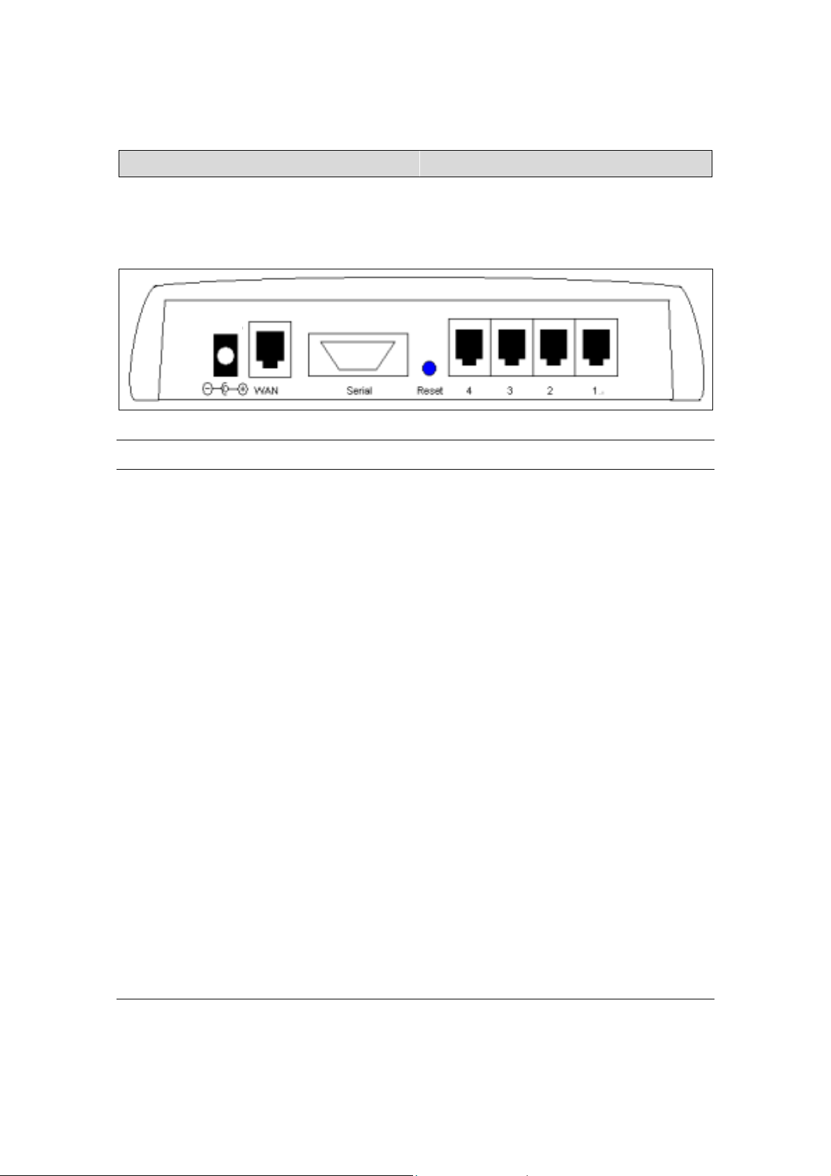
The Gateway’s Rear View
The diagram below shows the Internet Gateway’s rear panel and is where all
the hardware connections are made.
12VDC
Rear View Ports Description
Power (12VDC) The power port is where you connect the DC power
adapter
WAN The WAN 10M Ethernet port is where you connect your
ADSL/Cable modem.
Serial The Serial port is where you connect the 56K modem /
ISDN TA
Reset If you want the device to have the factory default settings,
press the reset button and hold it for 5 ~ 6 seconds. This
will load the factory default settings into the device.
Please be careful. Do not press the reset button
unless you want to clear the current configurations.
Ports 1-4 There are four LAN ports on the rear panel (supports
auto crossover). This is where you connect network
devices, such as PCs, switches, hubs, print servers, LAN
servers or other network devices.
4
Page 5
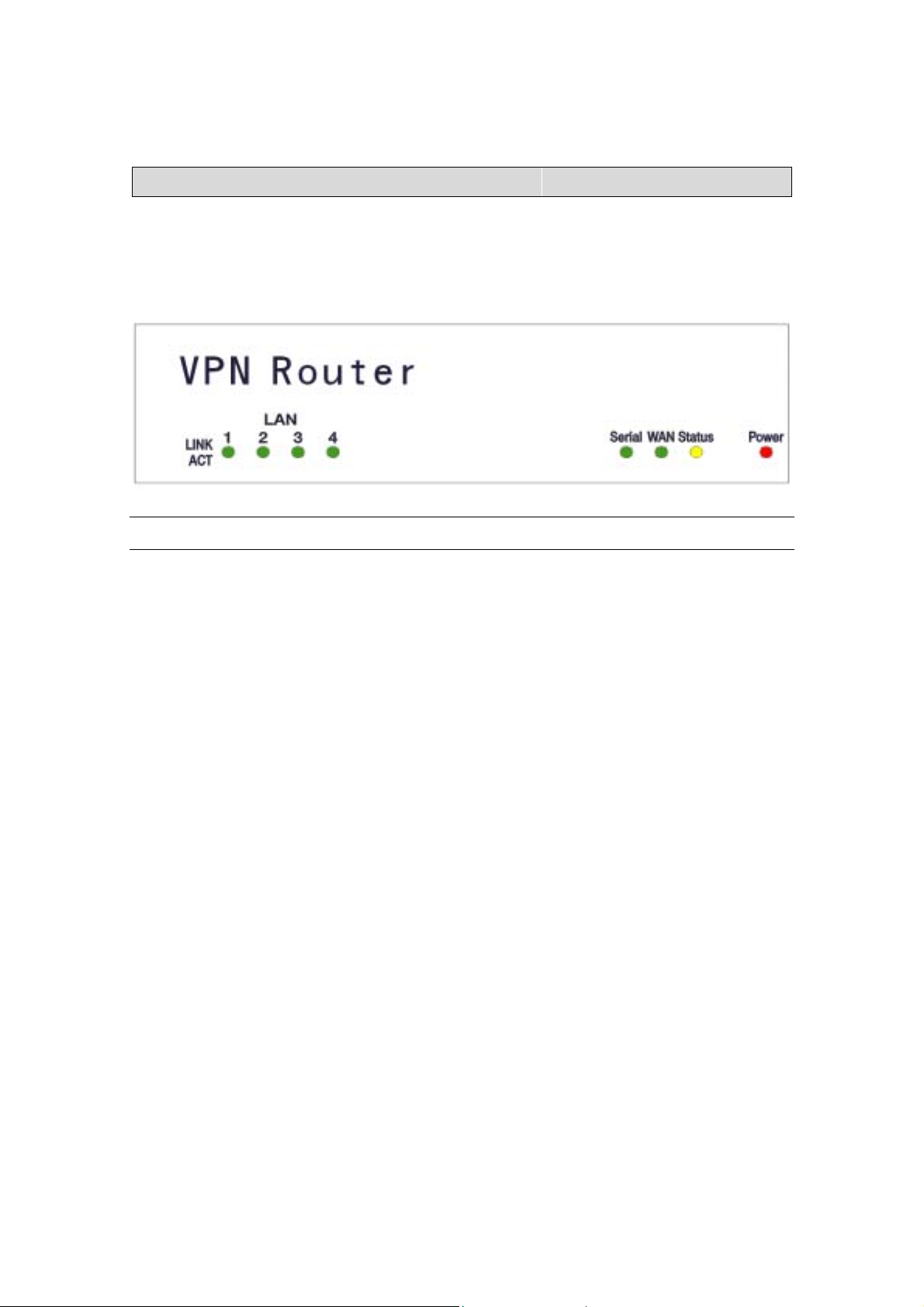
The Gateway’s Front Panel LED
On the router’s front panel there are LED lights that inform you of the router’s
current status. Below is an explanation of each LED and its function.
LED LED Status Description
LAN (1-4) Link/Act Off Green LED will NOT Light if there is no
connection
ON Green LED will LIGHT when a connection
has been established.
Blink Green LED will BLINK if packets are been
transmitted or received
Serial Off Green LED will NOT Light if there is no
connection
ON Green LED will LIGHT when a link
has been established.
WAN Off Green LED will NOT Light when a link has
not been established.
ON Green LED will LIGHT when a link has
been established.
5
Page 6
LED LED Status Description
STATUS Blink Yellow LED will BLINK when the device is
booting up or upgrading a firmware.
POWER Off NO Power
ON Red LED will LIGHT if the Gateway is
receiving power.
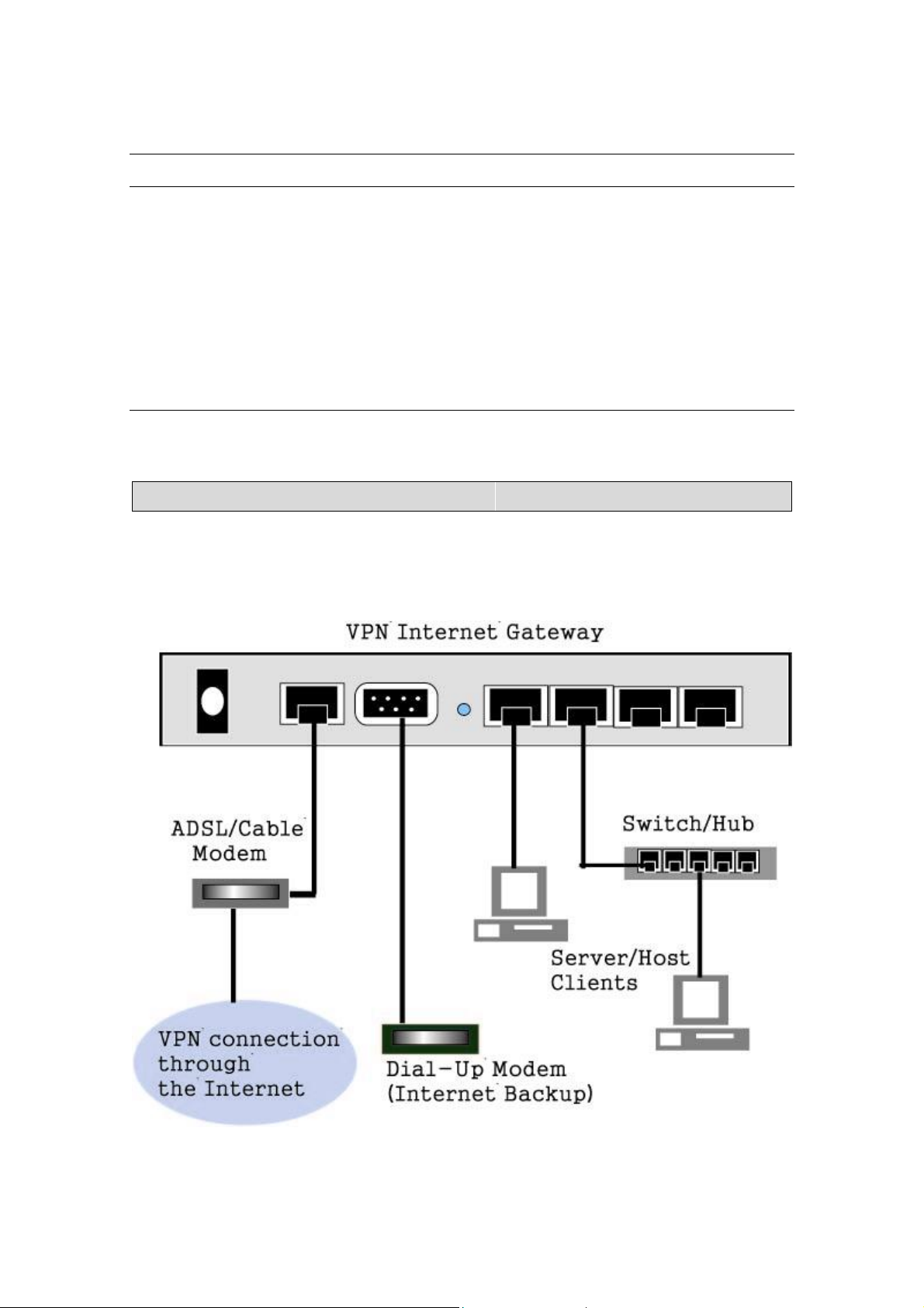
Hardware Installation Setup
The diagram below shows how the Internet Gateway is typically setup.
6
Page 7

When you setup the hardware installation please note the following.
1. Make sure that the power supply outlet voltage is compatible with the
power adapters of your PCs, Cable/XDSL modem and the Internet
Gateway.
2. For the Internet Gateway, only use the power adapter that comes with it.
3. Connect a network cable from your PC’s Ethernet port to one of the LAN
ports at the rear panel of the Internet Gateway. Do the same with all of
the PCs or switches/hubs you wish to connect to the Internet Gateway.
4. Connect the network cable from your Cable/XDSL modem to the WAN
Ethernet port at the rear panel of the Internet Gateway.
7
Page 8
Chapter 2: Getting Started
To setup the Internet Gateway and get connected to the Internet; follow the
following step-by-step procedure:
1. Setup your hardware network installation (see Chapter 1 – Hardware
Installation setup)
2. Configure your network computers (LAN server/client/host) to “Obtain an
IP address automatically.” (See Appendix)
Note: By default the Internet Gateway’s DHCP is enabled - so by setting
your computer to “Obtain and IP address automatically” - you can
connect to the Gateway automatically.
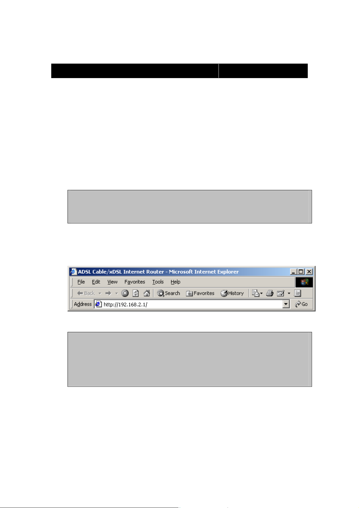
3. Launch your web browser and type the router’s default IP address
(http:// 192.168.2.1) into the browser’s address box and press Enter.
Note: If you have setup your computer to use a static IP address:
Please make sure your PC’s IP address is in the same network as the
router’s. In windows 95/98 you can type WINIPCFG and in windows
2000/NT you can type IPCONFIG (see appendix) to find out if you are
on the same network.
8
Page 9
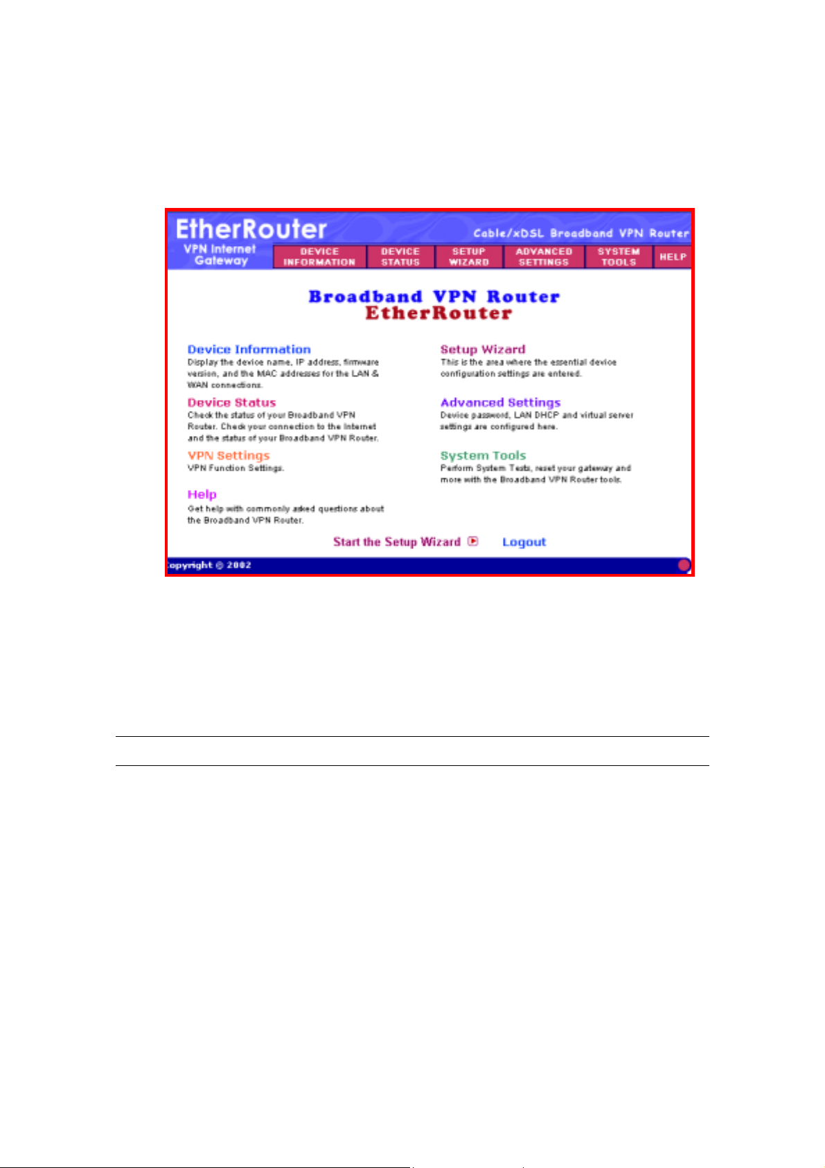
4. The main menu will appear. It displays all the functions that you can use
and configure for the Internet Gateway.
The User Interface is designed to be extremely user-friendly and is
divided into 6 main sections. The 6 sections are listed on the top Tool
bar (see screen above) and appear at the top of every browser screen
for easy access. For your reference the 6 sections are as follow:
Main Menu Description
Device Information (chapter 3) The Device information section displays
the Internet Gateway’s network and
firmware information.
Device Status (chapter 4) Device status displays the current
connection status of the Internet Gateway.
9
Page 10

Main Menu Description
Setup Wizard (chapter 2) This is the most important section out of
the 6 sections. You must configure this
section to begin using the Internet
Gateway. The Setup wizard is where you
input the information required to connect
the Internet Gateway to your Internet
Service Provider (ISP).
Advanced Settings (chapter 5) The Advanced settings section is where
you can configure all the major features
and functions of the Internet Gateway.
They include: DHCP Server Settings,
Virtual Server Settings, Routing Settings,
Filter Settings, Administration Settings,
Dynamic DNS Settings, URL Filter
Settings and E-Mail ALERT
System Tools (chapter 6) The System Tools section detects the
status of the Internet Gateway, such as
Intruder Detection Log, Display Routing
Table, System Diagnostics, Save Settings,
Load Settings, Upgrade Firmware and
Reset Device
Help (chapter 7) A help section for the Internet Gateway
10
Page 11
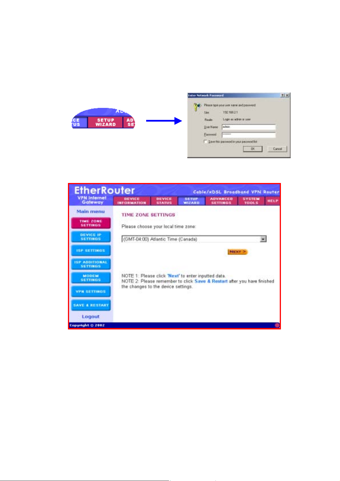
5. Click the SETUP WIZARD. A username and password will appear.
Leave the password box empty and type admin (the default username)
in the username box. Click OK.
The setup wizard’s page will appear as shown below.
The Setup wizard will take you through 7 step-by-step (7 steps: buttons
on the left) configuration procedures that you’ll need to do in order to
setup the Internet Gateway (e.g. connecting to the Internet / establishing
a VPN connection).
You can click on one of the 7 buttons on the left to jump to that specific
setting. Otherwise by clicking Next, you will proceed to the next step
sequentially. (We recommend that you follow the 7 steps sequentially).
The 7 steps are as follows:
11
Page 12
(Step A) Time Zone Settings
(Step B) Device IP Settings
(Step C) ISP Settings
(Step D) ISP Additional Settings
(Step E) Modem Settings
(Step F) VPN Settings
(Step G) Save & Restart
6. (Step A) Time Zone Settings: Please choose a local time zone. Once
you have selected a time zone, click the Next button to continue to the
next step.
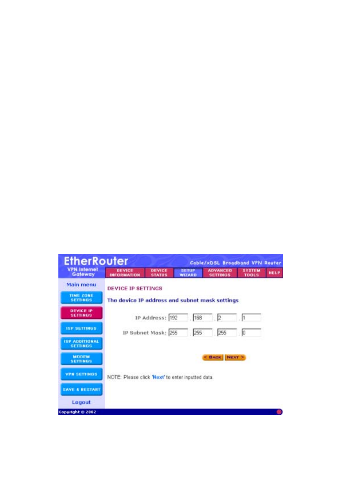
7. (Step B) Device IP Settings
In this section, you have to give your Internet Gateway an IP address for
the local area network (LAN) side. This is not the IP address given to
you by your ISP, but rather the local internal LAN (Private) IP address of
your network. The IP address “192.168.2.1” is the default value of your
Gateway.
12
Page 13

The screen shown above is described in the following table:
Parameters Description
Device IP Address Settings
IP Address Assign an internal LAN IP address for this
Internet Gateway or leave it as the default
value “192.168.2.1.”
IP Subnet Mask Enter the subnet mask, you can usually
leave it as the default entry
“255.255.255.0”
Once you have filled in the above information, click the Next button to
continue to the next step.
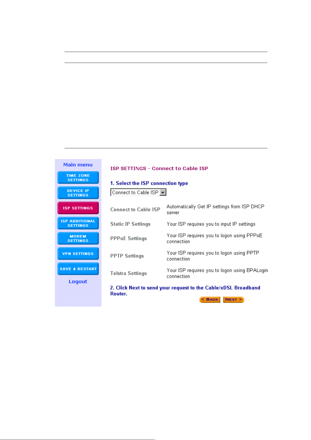
8. (Step C) ISP Settings
Different ISPs require different methods of connecting to the Internet.
The ISP Settings section is where you input all the information required
by your ISP, so that you can connect to the Internet. There are 5
different types of ISP connections in the ISP Settings section. Select the
connection required by your ISP from the Select the ISP connection
type pull down menu and then proceed to that connection type step.
The 5 ISP connection types are as follow:
ISP Connection Type Description
Connect to Cable ISP (Step 8-1) Your ISP will automatically give
you an IP address
Static IP Settings (Step 8-2) Your ISP has given you an IP
address already
PPPoE Settings (Step 8-3) Your ISP requires you to use a
Point-to-Point Protocol over
Ethernet (PPPoE) connection.
13
Page 14
ISP Connection Type Description
PPTP Settings (Step 8-4) Your ISP requires you to use a
Point-to-Point Tunneling Protocol
(PPTP) connection.
Telstra Settings (Step 8-5) The Telstra Settings is a service
that applies to connections in
Australia only.
Step 8-1) Connect to Cable ISP: Select Connect to Cable ISP if you
have a cable connection. Please select “Connect to Cable ISP”
and click “Next” to proceed to the next page. Proceed to step 9
(Step D) ISP Additional Settings of this manual
Step 8-2) Static IP Settings: Select Static IP Settings, if your ISP has
14
Page 15
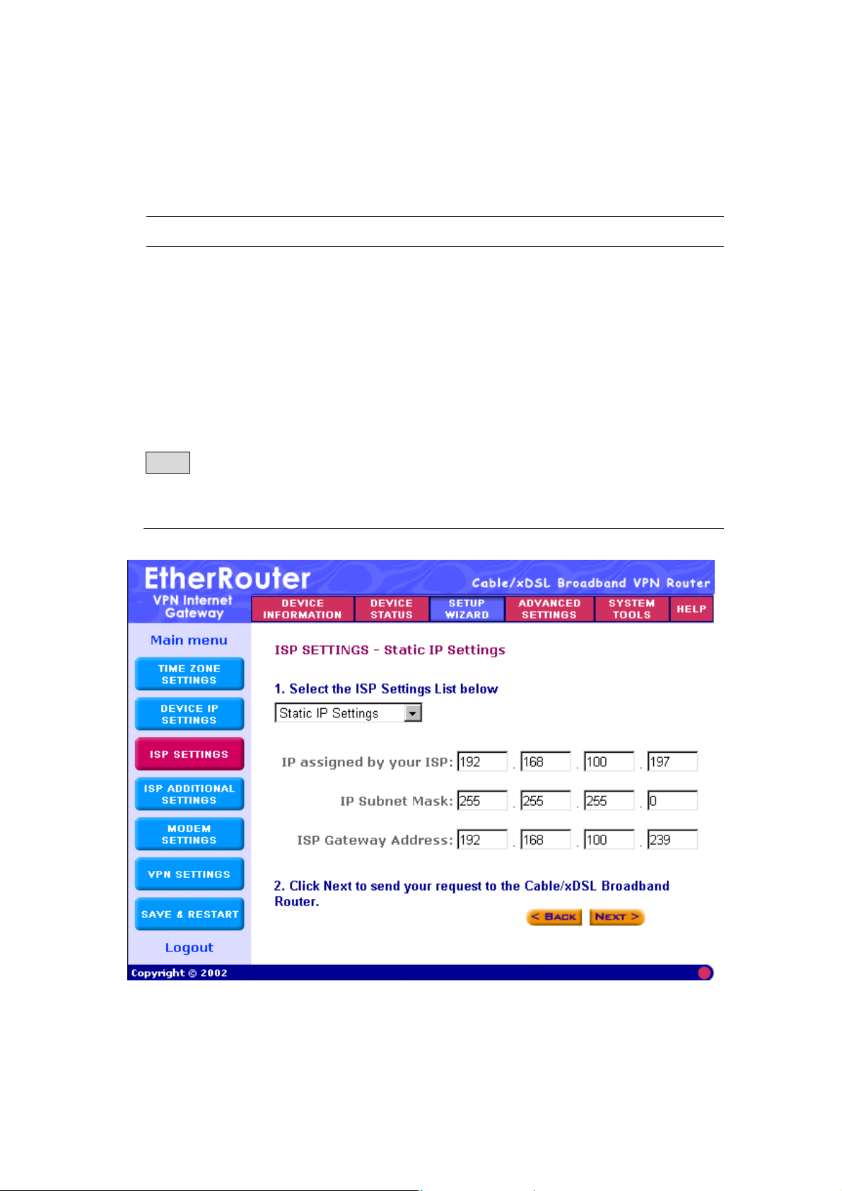
given you a static IP address. You will have to enter the following
information:
Parameter Description
IP assigned by your ISP Enter the IP address (provided by your ISP)
IP Subnet Mask Enter the IP subnet mask (provided by your ISP)
ISP Gateway Address Enter the ISP gateway address (provided by your
ISP)
Note: Once you have filled in the above information, click “Next” to proceed
to the next step. Proceed to step 9 (Step D) ISP Additional Settings of this
manual
15
Page 16

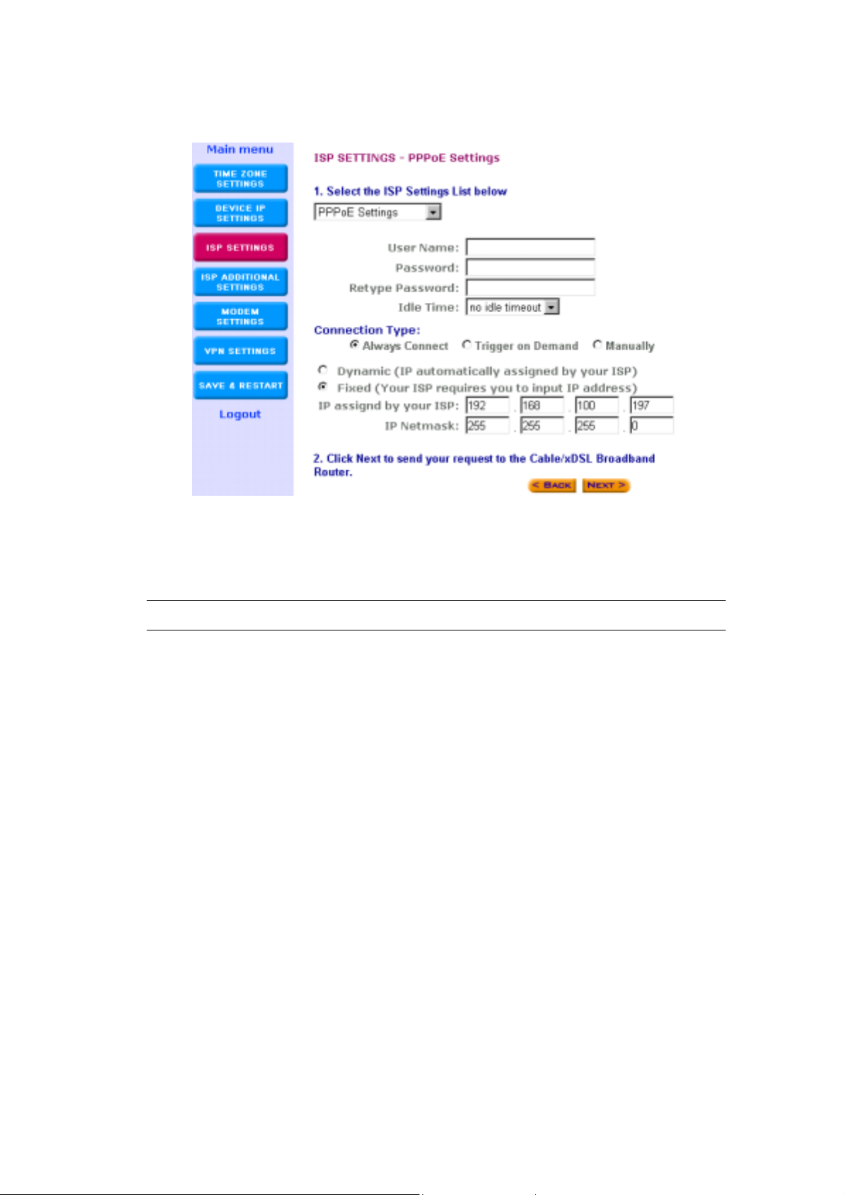
Step 8-3) PPPoE Settings: Select PPPoE Settings if your ISP requires the
PPPoE protocol to establish an Internet connection. You will
have to enter the following information:
Parameter Description
User name Enter the user name of your ISP account.
Password Enter the password of your ISP account.
Retype password Enter the password of your ISP account again to
re-confirm.
Connection Type Select ONE.
Always Connect - The VPN Gateway will always
connect with your ISP. If this is the case, the Idle
Time function is unavailable.
Trigger on Demand – Once the VPN Gateway
detects any packets want to get to Internet, the
VPN Gateway will connect with your ISP
automatically.
Manual – You can manually disconnect/connect
with your ISP for the WAN port (Cable/xDSL). If
this is the case, you have to go to the DEVICE
STATUS page and click Connect button to
establish the connection or click Disconnect
button to disconnect the connection.
Dynamic/Fixed: Select ONE.
Dynamic - If your ISP will automatically assign
you an IP address
Fixed - If your ISP has given you a fixed IP
address already, then enter that IP address in the
IP assigned by your ISP box. Also enter the
subnet mask (provided by ISP) in the IP Netmask
box
Note: Once you have filled in the above information, click “Next” to proceed
to the next step. Proceed to step 9 (Step D) ISP Additional Settings of this
manual
16
Page 17
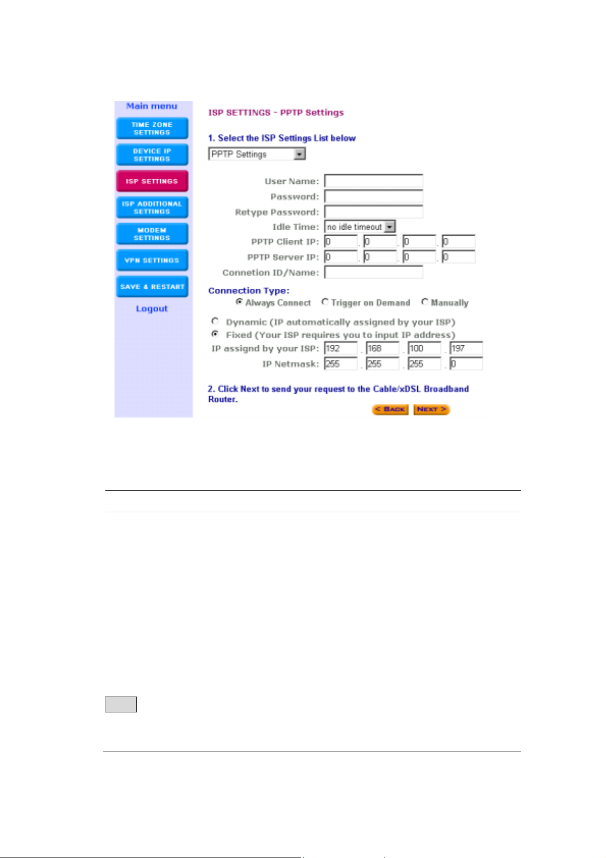
Step 8-4) PPTP Settings: Select PPTP Settings, if your ISP requires the
PPTP protocol to establish an Internet connection (e.g. Europe).
You will have to enter the following information:
Parameter Description
User name Enter the user name of your ISP account.
Password: Enter the password of your ISP account.
Idle Time Optional: You do not have to configure this
section. It depends on the user’s needs. If the
Internet connection has been idle for a certain
period of time (the Idle Time selected), the Idle
Time function will automatically disconnect the
Internet connection.
PPTP Client IP Enter the PPTP client IP address (Provided by
ISP)
17
Page 18

Parameter Description
Connection ID Input this ID information only if your ISP has
given you one.
Connection Type Select ONE.
Always Connect - The VPN Gateway will always
connect with your ISP. If this is the case, the Idle
Time function is unavailable.
Trigger on Demand – Once the VPN Gateway
detects any packets want to get to Internet, the
VPN Gateway will connect with your ISP
automatically.
Manual – You can manually disconnect/connect
with your ISP for the WAN port (Cable/xDSL). If
this is the case, you have to go to the DEVICE
STATUS page and click Connect button to
establish the connection or click Disconnect
button to disconnect the connection.
Dynamic/Fixed Select ONE.
Dynamic - If your ISP will automatically assign
you an IP address
Fixed - If your ISP has given you a fixed IP
address already, then enter that IP address in the
IP assigned by your ISP
box. Also enter the
subnet mask (provided by ISP) in the IP Netmask
box
Note: Once you have filled in the above information, click “Next” to proceed
to the next step. Proceed to step 9 (Step D) ISP Additional Settings of this
manual
18
Page 19
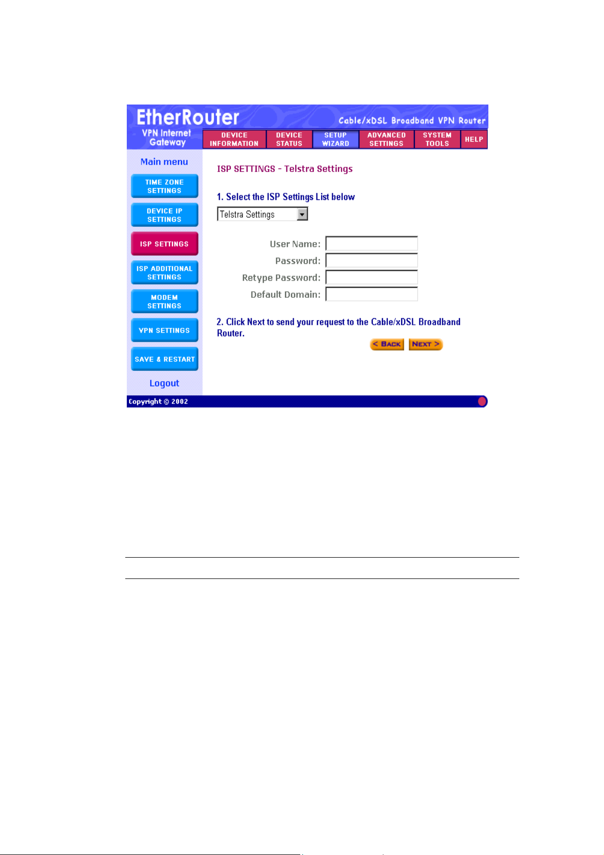
Step 8-5) Telstra Settings: The Telstra Settings is a service that applies to
connections in Australia only. You will have to enter the following:
Parameter Description
User Name Enter the User Name (Provided by the ISP)
Password Enter the Password (Provided by the ISP)
Retype password Re-Enter the password of your ISP account again
to re-confirm.
Default Domain Input the default domain if your ISP has given
you one
Note: Once you have filled in the above information, click “Next” to proceed
to the next step. Proceed to step 9 (Step D) ISP Additional Settings of this
manual
19
Page 20
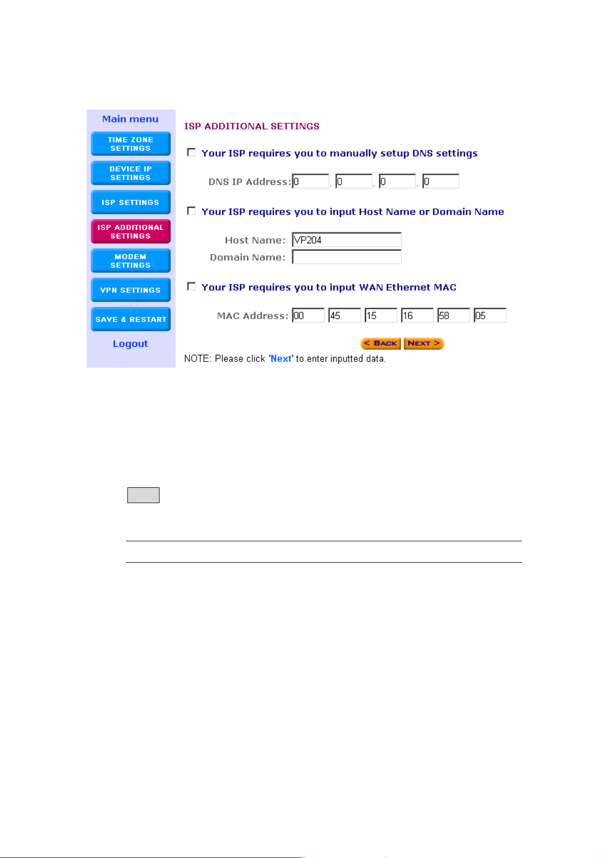
9 (Step D) ISP Additional Settings
In this section you can input special settings required by certain ISPs.
You do not need to configure the entire section or any part of the section,
only the settings needed by your particular ISP (if any). If your ISP does
not require any additional settings, then please leave this section blank
and proceed to the next step.
Parameter Description
Your ISPs require If your ISP requires you to input a DNS
you to manually setting then you must check this box to
setup the DNS settings enable this function and then enter the
DNS address (see DNS IP Address
below)
DNS IP Address Enter the DNS IP address (provided by
ISP)
20
Page 21

Parameter Description
Some ISPs use Host Name If your ISP requires you to fill in a Host
and Domain Name to Name and Domain Name then you must
authenticate the user check this box to enable this function and
then enter the Host Name and Domain
Name (see Host/Domain Name below)
Host Name Enter the Host Name (provided by your
ISP)
Domain Name Enter the domain name (provided by your
ISP)
Your ISPs require you to If your ISP requires a specific MAC
input the LAN card’s address in order for you to connect
Mac address to the Internet, then check the box to
enable this function and then enter the
Mac address (see MAC Address below)
NOTE: Some ISPs may only recognize
your PC’s LAN card MAC address as a
legal user. In this case, you will have to
copy the LAN card MAC address of that
PC and input it in the MAC address field.
For WIN 95/98 you can run winipcfg to
see the LAN card Mac address
For WIN 2000/NT you can run
ipconfig/all to see the LAN card Mac
address
MAC Address Enter the PC’s LAN card MAC address
that your ISP recognizes as the legal user
Note: Once you have filled in the above information, click “Next” to
proceed to the next step.
21
Page 22
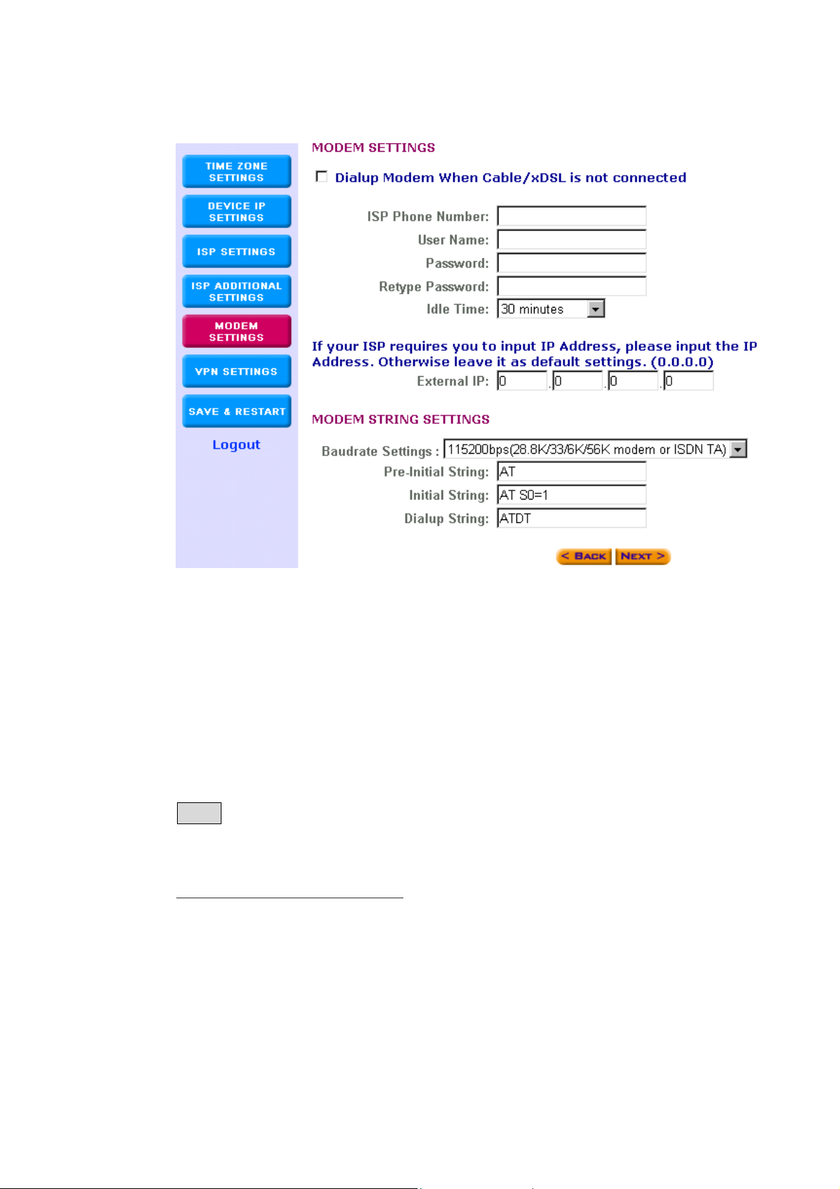
10. (Step E) Modem Settings
The modem settings screen is where you can setup the asynchronous
port as either a backup connection for the Cable/xDSL connection or a
dialup Internet access connection.
Note: This section is Optional. You may proceed to Step F if you do not
wish to use the asynchronous port.
Parameter Description
Dialup Modem When Click on this box to enable
Cable/xDSL is not the asynchronous port
Connected
ISP Phone Number Enter the ISP phone number (Dial-Up)
User Name Enter the User Name for the dial-up
Password Enter the Password for the dial-up
22
Page 23

Parameter Description
Retype Password Enter the Password again to re-confirm
Idle Time You can select an idle time threshold
(minutes) for the WAN port. This means if
no packets have been sent (no one using
the Internet) throughout this specified
period, then the router will automatically
disconnect with your ISP.
External IP (Optional) If your ISP requires you to
input an IP address then please input the
IP address here. Otherwise leave it as the
default setting (0.0.0.0).
Modem String settings (Optional) Some modems require specific
communication strings. This section
allows you to specify strings on the router,
so that it can communicate with your
modem (if required). If you would like to
change the baudrate speed, you can do
so in the Baudrate Settings field. (Please
refer to your modem’s or ISDN TA’s
manual for more information)
Note: Once you have filled in the above information, click “Next” to
proceed to the next step.
23
Page 24
11. (Step F) VPN Settings
The VPN Settings section is where you can enable and configure the
VPN function. Specifically, this device supports the widely used IPSec
protocol standard for its VPN connection. VPN allows a secure
connection between two parties over a public network, such as the
Internet.
Note: This section is Optional. You may proceed to Step G if you do
not wish to establish a VPN connection.
The VPN settings has 3 steps:
11-1) Add a VPN connection: Connection Name
11-2) Configure the VPN Connection
11-3) Secure Association
24
Page 25
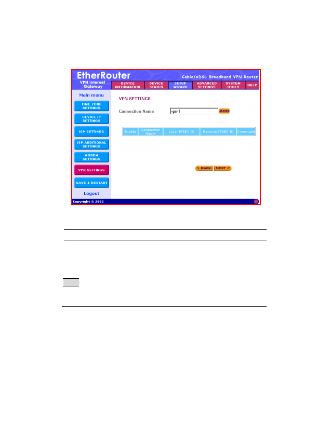
11-1) Add a VPN connection: Connection Name
Parameter Description
Connection Name To add a VPN connection: Enter a string
(name) into the Connection Name box,
and then click the “ADD” button.
Note: Once you have entered the connection name - click on the “ ADD”
button to start configuring this VPN connection. The screen below will
appear and this is where the VPN configuration is entered.
25
Page 26

11-2) Configure the VPN Connection
Parameter Description
Connection Name This is the Connection Name you entered
in the previous screen (Connection Name)
Enable UID Optional - This will enable the Unique
Identifier string (UID). Disable UID will
disable the UID. The VPN Gateways use
the UID for authentication purposes. (see
Local/Remote IPSEC Identifier below)
Local IPSEC Identifier Optional - This field allows you to identify
multiple tunnels; you don’t need to match
the name used at the other end of the
tunnel. You can enter a proper name in
this field; the default value for the Local
IPSEC Identifier is, Local
26
Page 27

Parameter Description
Remote IPSEC Identifier Optional - This field allows you to identify
multiple tunnels; you don’t need to match
the name used at the other end of the
tunnel. You can enter a proper name in
this field; the default value for the Remote
IPSEC Identifier is, Remote
Enabled Keep Alive Optional - If this function is enabled, it will
keep this VPN connection alive
(connected)
Enabled NetBIOS Optional - This function allows NetBIOS
Broadcast broadcast to be transmitted in this VPN
connection
Remote Site Select One:
Single User – Select Single User if
the remote VPN site is a VPN client, e.g.
remote site has no Internet gateway.
The remote VPN client must have a
VPN client software installed (e.g.
Safenet or SSH etc.)
LAN – Select LAN if the remote VPN
site has an Internet gateway.
Remote IP Network This is the remote site’s NETWORK IP
address. (Single User – Input the actual
IP address of the Remote VPN client.
LAN – Input the network IP of the remote
gateway’s internal (private) network)
27
Page 28

Parameter Description
Remote IP Netmask This is the remote site’s subnet mask
Remote Gateway IP/FQDN Input the remote site’s Gateway IP
address (for Remote Site – LAN only) or
the Fully Qualified Domain Name (FQDN).
FQDN consists of a host
and domain
name, including top-level domain. For
example, WWW.VPN.COM is a fully
qualified domain name. WWW is the host,
VPN is the second-level domain, and
COM is the top-level domain. When you
enter the FQDN of the remote site, the
VPN gateway will automatically seek the
IP address of that FQDN.
Note: In IKE Mode, if the Remote
Gateway IP has a dynamic IP address,
you must enter “0.0.0.0.” in the Remote
Gateway IP/FQDN field. In Manual Mode,
you must fill in the Remote IP, Remote IP
Network and Remote Gateway IP/FQDN
field (Remote Gateway IP/FQDN field
cannot be 0.0.0.0 for the manual mode).
See Appendix - VPN example.
Network Interface Select an interface type for the this VPN
connection
28
Page 29

11-3) Secure Association
Secure Association is a method of establishing a security policy between
two points.
There are two methods of creating a Secure Association (SA),
Method 1: IKE Mode (By default IKE is selected),
Method 2: Aggressive mode and
Method 3: Manual mode.
11-3) Method 1: IKE Mode:
IKE is an automated method of establishing a shared security policy
and authenticated keys. A preshared key is used for mutual
identification.
Parameter Description
Perfect Forward Secure Click either the Enabled or Disabled radio
button. This feature provides a better
security; it ensures that the encryption
keys generated are not relevant to each
other.
Encryption Protocol The VPN Gateway supports two types of
encryption algorithms (DES and 3DES).
Select an appropriate encryption
algorithm. The encryption algorithm must
match the encryption algorithm in the
remote device.
29
Page 30

Parameter Description
PreShared Key Enter the PreShared Key name (you can
enter a alphanumeric name). This value
must match the preshared key value in
the remote device.
Key Life Security is enhanced if the key used to
encrypt/decrypt your data is changed
periodically. The key life is where you can
specify how often you wish the VPN
Gateway to renegotiate another key. The
value is in seconds, for example, 3600
seconds = 1 hour.
IKE Life Time The IKE Life Time field allows you to
specify a period of time (seconds) that
you want the VPN Gateway to renegotiate
the IKE security association. For example,
28800 seconds = 8 hours.
Note: In IKE Mode, if the Remote Gateway IP is dynamic, you should
enter “0.0.0.0” See Appendix - VPN example.
30
Page 31

11-3) Method 2: Aggressive mode
Aggressive is an automated method of establishing a shared security
policy and authenticated keys. A preshared key is used for mutual
identification.
Parameter Description
Perfect Forward Secure Click either the Enabled or Disabled radio
button. This feature provides a better
security; it ensures that the encryption
keys generated are not relevant to each
other.
Encryption Protocol The VPN Gateway supports two types of
encryption algorithms (DES and 3DES).
Select an appropriate encryption
algorithm. The encryption algorithm must
match the encryption algorithm in the
remote device.
Key Group Diffie-Hellman key agreement describes a
method whereby two parties, without any
prior arrangements, can agree upon a
secret key that is known only to them. The
VPN Gateway supports two versions of
Diffie-Hellman (Group 1 and Group 2).
31
Page 32

Parameter Description
Diffie-Hellman Group 1 - IKE use the 768-
bit Diffie-Hellman prime modulus group
when performing the new Diffie-Hellman
exchange.
Diffie-Hellman Group 2 - IKE use the
1,024-bit Diffie-Hellman prime modulus
group when performing the new DiffieHellman exchange.
PreShared Key Enter the PreShared Key name (you can
enter a alphanumeric name). This value
must match the preshared key value in
the remote device.
Key Life Security is enhanced if the key used to
encrypt/decrypt your data is changed
periodically. The key life is where you can
specify how often you wish the VPN
Gateway to renegotiate another key. The
value is in seconds, for example, 3600
seconds = 1 hour.
IKE Life Time The IKE Life Time field allows you to
specify a period of time (seconds) that
you want the VPN Gateway to renegotiate
the IKE security association. For example,
28800 seconds = 8 hours.
Note: In Aggressive Mode, if the Remote Gateway IP is dynamic, you
should enter “0.0.0.0” See Appendix - VPN example.
32
Page 33

11-3) Method 3: Manual mode
This is a manual way of establishing a shared security policy and
authenticated keys. The Manual mode allows you to pre-define keys.
The Manual Mode settings in the remote device must match the
configuration set here. To enable the Manual mode function, check the
Manual radio box and input the fields shown on the screen below.
Parameter Description
Incoming SPI Enter the Incoming SPI that the remote
VPN Gateway will use to identify this SA.
The incoming SPI value must match the
outgoing SPI at the remote site (other end
of the VPN tunnel).
Outgoing SPI Enter the Outgoing SPI that the local VPN
Gateway will use to identify this SA. The
outgoing SPI value must match the
incoming SPI at the remote site (other end
of the VPN tunnel).
Encryption Protocol The VPN Gateway supports three types of
encryption algorithms (Null, DES, and
3DES). Select an appropriate encryption
algorithm. The encryption algorithm must
match the encryption algorithm in the
remote device.
33
Page 34

Parameter Description
Encryption Key This string is used as the key to encrypt
and decrypt the data transmitted. This
value must match the encryption key
value in the remote device.
Authentication Protocol The VPN Gateway supports two
authentication algorithms (MD5 & SHA-1).
Select an appropriate authentication
algorithm. The authentication algorithm
selected here must be the same as the
one in the remote device.
Authentication Key This string is used as the key
authentication. This value must match the
authentication key value in the remote
device.
Note: In Manual Mode, you must fill in the Remote IP, Remote IP
Network and Remote Gateway IP/FQDN (Remote Gateway IP/FQDN
field cannot be 0.0.0.0.). See Appendix - VPN example.
34
Page 35

12. (Step G) Save & Restart
This is the final step of the Setup Wizard’s 7 step-by-step procedure.
This step saves the settings you have made in the previous pages to the
Internet Gateway. Click Save & Restart to save the settings and to
restart the device. After the device has restarted, the device will function
according to the saved settings.
During the startup process the LED of the device will blink. Please wait
until the LED lights have stopped blinking before proceeding.
35
Page 36

Logout
Click Logout if you would like to leave (logout) the router ’s web based
configuration page. Only one user can log onto the Gateway’s web
based configuration at a time. When you logout of the web-based
configuration, only then can another computer log onto the device.
Click Yes - the screen will close.
Click No - the screen will not close.
Congratulations!!! You have successfully configured the setup wizard.
You may now use the Internet Gateway to access the Internet.
If you would like to configure or monitor the many features that this Gateway
has to offer, then proceed to the appropriate chapters for more details. Below is
a list of the other Main Menus and their corresponding chapters:
Device Information (chapter 3)
Device Status (chapter 4)
Setup Wizard (chapter 2)
Advanced Settings (chapter 5)
System Tools (chapter 6)
Help (chapter 7)
36
Page 37

Chapter 3: Device Information
The Device information section displays the Internet Gateway’s network and
firmware information.
Parameters Description
Device Name Displays the name of the Internet
Gateway
IP Address Displays the IP address of the Internet
Gateway
Private LAN MAC Address Displays the MAC address of the Internet
Gateway’s LAN port
Public WAN (Cable/XDSL) Displays the MAC Address of the Internet
Mac Address Gateway’s WAN Ethernet port
Firmware version Displays the Internet Gateway’s current
Firmware Version and its release date
37
Page 38

Chapter 4: Device Status
Device status displays the current connection status of the Internet Gateway.
Parameter Description
WAN Ethernet Shows the Device’s WAN information:
Cable/xDSL (shows whether the Internet
connection is active or inactive), Connected by
DHCP (shows the WAN connection type e.g.,
DHCP, Static, PPPoE, PPTP or Telstra), ISP’s
Gateway IP address, device’s WAN IP address,
device’s Netmask and the DNS IP address that
the Internet Gateway is using.
38
Page 39

Parameter Description
Release (Disconnect) and Renew (Connect)
You can manually disconnect/connect with your
ISP for the WAN port (Cable/xDSL)
Click the Release (Disconnect) button - the
Internet Gateway will disconnect with the ISP.
Click the Renew (Connect) button - the Internet
Gateway will connect with the ISP.
Modem Dialup The modem (asynchronous port) can be used as
a backup Internet connection (dialup) for the
Cable/xDSL connection or as an Internet access
connection. If the current connection is via the
backup modem, it will show “Modem: Active,”
otherwise it will show “Not Active”.
Hang Up and Dial Up You can manually disconnect/connect with your
ISP for the asynchronous port (Dial Up/ISDN TA)
If the Modem Dialup shows Modem: Active,
clicking on the Hang Up button will
DISCONNECT the asynchronous port’s Internet
connection.
If the Modem Dialup shows Not Active, by
clicking on the Dial Up button - the Internet
Gateway will ESTABLISH an Internet connection
for the Gateway’s asynchronous port.
Device IP Shows the Device’s: LAN IP address, private
LAN MAC address and public WAN MAC
address.
39
Page 40

Parameter Description
VPN Status This screen displays the current connection
status of your VPN connection(s). The VPN
connection status shows the following
information:
Status - Active/Inactive
Connection Name - name of the VPN connection
Remote IP, Virtual Network - remote site’s
Network (private network) IP
Interface, Type – encryption / authentication
State - phase 1 / phase2
TX pkts - transmitted packets
Rx pkts - received packets
UpTime - how long the connection has been
established
Drop - click the Drop button to disconnect the
VPN connection
40
Page 41

Parameter Description
DHCP Log Displays the DHCP clients logged to the
Gateway’s DHCP server.
Click the DHCP Log button - the screen will
display the DHCP client’s information (DHCP
client’s: IP address, MAC address, IP address
lease time).
VPN Log This screen displays the VPN negotiation that
occurred between the VPN Gateway and remote
devices.
Click on Refresh – to update the latest
information
Click on Clear Log – to clear the VPN log
41
Page 42

Parameter Description
Update DDNS Click the Update DDNS button to manually
update the IP address of your domain name
(dynamic IP address for Gateway’s WAN port).
Note: DO NOT click the Update DDNS button too
often. Some ISP’s may think this is an attack and
may disable your account.
42
Page 43

Chapter 5: Advanced Settings
The Advanced settings section is where you can configure all the major
features and functions of the Internet Gateway. They include: DHCP Server
Settings, Virtual Server Settings, Routing Settings, Filter Settings,
Administration Settings, Dynamic DNS Settings, URL Filter Settings and E-Mail
ALERT
On the Menu Tool, click Advanced Settings.
A username and password will appear.
Type “admin” in the user name box, and
then type the password that you have given to
the device (by default there is no password)
and then Click OK. The Advanced
Settings page will appear as shown below.
43
Page 44

Main Menu Description
DHCP Server Settings Provides centralization of all your LAN’s
network IP addresses
Virtual Server Settings Allows remote access to Web, FTP, and
other services on your network. The DMZ
function allows full 2-way communication
between a server on your LAN and the
Internet
Routing Settings Create a routing table so that the Internet
Gateway can route packets to different
networks
Filter Settings Create LAN or WAN filters to protect your
network
Administration Settings Allows you to configure the device’s
administrative settings such as password
etc.
Dynamic DNS Settings Allows you to have a Web or other server
behind a Dynamic IP address
URL Filter Settings Filter web page request based on the web
page’s wording
E-Mail ALERT Allows you to be alerted of any security
infringements
Logout Logout or leave the Internet Gateway’s
Web-based configuration
44
Page 45

DHCP Server Settings
You can enable or disable the DHCP server. By enabling the DHCP server the
router will automatically give your LAN clients an IP address. If the DHCP is not
enabled then you’ll have to manually set your LAN client’s IP addresses. Make
sure the LAN Client is on the same subnet as this Internet Gateway if you want
this Internet Gateway to be your LAN client’s default gateway.
Parameter Description
Enable DHCP By default the Internet Gateway’s DHCP
Server Functions server is enabled. If you would like to disable the
DHCP server, unclick the Enable DHCP Server
Functions box (marked red - see screen above)
45
Page 46

Parameter Description
IP Address Pool Range The IP address pool contains the range of IP
addresses that will be used by the device’s DHCP
server to automatically assign IP addresses to
your network clients.
The Default IP address range is:
From 192.168.2.2 to 192.168.2.100
IP Address Reservation The IP address reservation setting allows you to
save fixed private IP address for specific
computer/network clients.
MAC Address: Enter the MAC address of the
PC or server you wish to reserve an IP for.
IP Address: Enter the IP address that you want
to reserve for the above MAC address.
Add an IP address Reservation setting
Click the Add button to add the configuration into
the IP address reservation table.
Delete an IP address Reservation setting
Check the IP address reservation table’s Del box
and click the DEL button to delete a configuration.
46
Page 47

Virtual Server Settings
Use the Virtual Server function when you want different servers/clients in your
LAN to handle different service/Internet application type (e.g. Email, FTP, Web
server etc.) from the Internet. Computers use numbers called port numbers to
recognize a particular service/Internet application type. The Virtual Server
allows you to re-direct a particular service port number (from the Internet/WAN
Port) to a particular LAN private/internal IP address.
The Virtual server settings allow clients on the Internet to access certain
services on your LAN via the Internet. Use the Virtual Server function to access
a Web, FTP or a Telnet server etc. on your LAN via the Internet.
The DMZ function re-directs all packets (regardless of services) going to your
WAN IP address to a particular LAN client/server. If you would like to enable the
DMZ function, enter an IP address in the DMZ IP field. The value ‘0’ means
that the DMZ function is disabled.
The difference between the virtual server and the DMZ function is that the
virtual server re-directs a particular service/Internet application (e.g. FTP,
websites) to a particular LAN client/server, whereas DMZ re-directs all packets
(regardless of services) going to your WAN IP address to a particular LAN
client/server.
47
Page 48

Parameter Description
DMZ Enter the IP address that you want to designate as the
DMZ server. The value ‘0’ means that the DMZ function
is disabled.
Virtual Server Settings
Internal IP Enter the LAN server/host IP address that the service
(Service Port Range) requests from the Internet will be
sent to.
Note: You need to give your LAN server/host a
fixed/static IP address for the Virtual Server to work
properly.
Service Port Range Enter the port numbers of the services (requests from the
Internet) that will be sent to the Internal IP address
(Specified above).
Note: If you only want one service port number e.g. 80
(HTTP) for the specified Internal IP address then enter
80 in both the service port range’s boxes.
The Table on the right side of the screen lists the most
popular applications and their port numbers.
48
Page 49

Routing Settings
The Static routing settings allow the Internet Gateway to route IP packets to
another network (subnet). The routing table stores the routing information so
that the Internet Gateway knows where to redirect the IP packets.
Parameters Description
Destination IP Address Enter the destination IP address of the remote
network to which you want to assign a static route.
Subnet Mask Enter the subnet mask of your network IP
address.
Gateway IP Address Enter the IP address of the interface (LAN/WAN
port) linked to the remote network (Destination IP
address).
Add a Static Routing setting
Click the Add button to add the configuration into
the Static Routing table.
49
Page 50

Parameters Description
Gateway IP Address
Delete a Static Routing setting
Check the Static Routing table’s Del box and click
the DEL button to delete a configuration.
Dynamic routing settings Allows the Internet Gateway to route IP packets
to another network automatically (dynamically).
The RIP protocol is used to do the dynamic
routing. RIP communicates routing information
with other routers periodically.
SEND Optional - choose the routing protocol
(routing information) that you wish to transmit to
other routers on your network.
RECEIVE Optional - choose the routing protocol
(routing information) that you wish to receive from
other routers on your network.
NOTE: Click the SUBMIT button to input/save the configuration into the
Gateway
50
Page 51

Filter Settings
The Filter Settings is divided into LAN Filter Settings and WAN Filter Settings
Menu Description
LAN Filter Settings The LAN Filter Settings allow the administrator
to define whether a local user is permitted to
access the Internet.
WAN Filter Settings The WAN Filter Settings allow the administrator
to define whether a remote/outside user(s) is
permitted to access the private local area network.
51
Page 52

Filter Settings: LAN Filter Settings
The LAN Filter Settings allow the administrator to define whether a local user
is permitted to access the Internet. To activate this feature, check LAN Side
Filter Enabled and then define a filtering policy. To define a filtering policy:
enter the IP address range, enter the network port number and select the
transport protocol(s).
Parameter Description
LAN Side Filter Enabled You must select whether to enable (Yes) or
disable (No) the filter function that you’ve
configured in this screen
Default LAN Side Filter Select to Block or Pass your regular LAN clients
Filter Entry Select to Block or Pass LAN clients specified in
this Filter Entry
52
Page 53

Parameter Description
Protocols Select the Transport protocol type (TCP or UDP)
for the Destination Port Range (below) that will
be filtered
IP Address Range Enter the LAN IP address range that you wish to
apply this filter rule to. These are the LAN users’
IP addresses that you wish to apply this filter rule
to. If you only want to specify one IP address for
this filter rule then enter the same IP address in
both the From and the To box.
Note: You need to give your LAN PC clients a
fixed/static IP address for the filter rule to work
properly.
Destination Port Range Enter the Internet application/service (port
number range) for the above IP address range
that you wish to apply this filter rule to. If you only
want to specify one service port then input the
same service port in both the boxes.
Add a Filter Entry setting
Click the Add button to add the configuration into
the LAN Side Filter Table .
Delete a Filter Entry setting
Check the LAN Side Filter Table’s Del box and
click the DEL button to delete a configuration.
53
Page 54

For example, to prevent local users with IP addresses (ranging from 101 to 200)
from accessing websites (HTTP service - port 80), the settings are as follow:
LAN Side Filter Enabled: Enabled
Default LAN Side Filter: Pass
Filter: Block
Protocol: TCP
IP Address Range: 101 ~ 200
Destination Port Range: 80 ~ 80 (HTTP)
Filter Settings: WAN Filter Settings
The WAN Filter Settings allow the administrator to define whether a
remote/outside user(s) is permitted to access the private local area network. To
activate this feature, check WAN Side Filter Enabled and then define a filtering
policy. To define a filtering policy: enter the IP address range, enter the network
port number and select the transport protocol(s).
54
Page 55

Parameter Description
WAN Side Filter Enabled You must select whether to enable (Yes) or
disable (No) the filter function that you’ve
configured in this screen
Default WAN Side Filter Select to Block or Pass your regular WAN users
Filter Entry Select to Block or Pass WAN clients specified in
this Filter Entry
Protocol Select the Transport protocol type (TCP or UDP)
for the Destination Port Range (below) that will
be filtered
IP Address Range Enter the (Public) IP address range that you wish
to apply this filter rule to. These are the external
users’ IP addresses that you wish to apply this
filter to. If you only want to specify one external IP
address for this filter rule then enter the same IP
address in both the From and the To box.
Note: WAN clients must have a fixed/static Public
IP address for the filter rule to work properly.
Destination Port Range Enter the Internet application/service (port
number range), for the above IP address range,
that you wish to apply this filter rule to. If you only
want to specify one service port then input the
same service port in both the boxes.
Add a Filter Entry setting
Click the Add button to add the configuration into
the WAN Side Filter Table.
Delete a Filter Entry setting
Check the WAN Side Filter Table’s Del box and
click the DEL button to delete a configuration.
55
Page 56

For example, to prevent remote users with IP addresses (ranging from
211.21.0.1 to 211.29.0.1) from accessing your LAN’s virtual Web server (port
80), the settings are as follow:
WAN Side Filter Enabled: Enabled
Default WAN Side Filter: Pass
Filter: Block
Protocol: ALL
IP Address Range: 211.21.0.1 to 211.29.0.1
Destination Port Range: 80 ~ 80 (HTTP)
Administration Settings
The Administration Settings section allows you to configure the device’s:
Password settings, System Administration, System Log, System Parameters,
UPnP and TCP session.
56
Page 57

Parameter Description
PASSWORD SETTINGS You can setup the Internet Gateway so that a
password is required, in order to access its webbased configuration pages. This password will be
required the next time you want to configure the
Internet Gateway. To setup a password, type
your password in the New Password field and
type it again in the Retype Password field to
reconfirm.
Note: It is important to remember your password.
If for any reason you lose or forget your password,
press the small reset button located on the back
of the device for 5~6 seconds. The Reset action
will reset the device to the factory default settings.
In factory default, the user name is admin and
there is NO password
SYSTEM ADMINISTRA TION This allows remote user(s) to configure and
manage the Internet Gateway from a remote site
(through the Internet).
The default value of the HTTP port No is 80. You
can select a different port number to do the
remote web-based configuration
The default IP address of the Remote
administration host is: 0.0.0.0. (IP address
0.0.0.0 means that any remote PC can access
and manage the Internet Gateway from a remote
site). Either specify an IP address for the remote
administrator or leave it as the default.
57
Page 58

Parameter Description
SYSTEM ADMIN You will have to enable the Allow remote user to
configure the device to use the remote web-
based configuration function. Once you have
enabled this function, type the device’s WAN IP
address and the HTTP port No
(e.g. http://202.19.100.1:1023) into the browser
of the specified remote administrator.
<
>
<
>
If the HTTP port number, is NOT the default
PORT No. 80, then the LAN administrator
must
also enter the new port number, specified in
HTTP port No, in order to access the device’s
web-based configuration, e.g. Device LAN IP
address with HTTP port no 1023
(http://192.168.2.1:1023)
Allow remote user to ping the device: If you
enable this function – the device will respond to
any pings it gets from the Internet. If you disable
this function, the device will not respond to any
ping requests.
SYSTEM LOG The System Log function allows the administrator
to assign an IP address to a server on which a
log server is running. When a particular event
occurs, the router will send a notification to the
log server. The log server can then present the
log to the administrator. [Free log server can be
downloaded from Internet, such as Kiwis SysLog
Daemon]
58
Page 59

Parameter Description
Miscellaneous Some ISPs require you to force a PPPoE
re-connection, when the Internet connection
cannot send or receive packets.
System Parameter The System Parameter allows you to set the MTU
value (Maximum Transmission Unit) for your
Internet connection. If you would like to enable
the MTU setting – check the box. The default
MTU value is 1500 bytes.
Some ISPs restrict the packet size for a PPPoE
connection. Use the system parameter to change
the MTU to cater to your ISP’s connection
requirement.
UPnP The Universal Plug and Play (UPnP) function
allows Windows XP to automatically configure the
router to cater to various Internet applications
(such as games and videoconferencing).
NOTE: Click the SUBMIT button to input/save the configuration into the
Gateway
59
Page 60

Dynamic DNS Settings
The Dynamic DNS (DDNS) service allows Web or other servers, with a dynamic
IP address, to be accessible from the Internet. This means that even if your
Internet Gateway has a dynamic WAN IP address, Internet users can still
access your web server (domain name) in your LAN.
If you would like to use the DDNS function, you will have to register with a
DDNS service provider, and enter the following information provided by the
DDNS service provider:
Parameter Description
Use a dynamic DNS Click on this box to enable the DNS service function
Service
Server Select the DDNS service provider that you have
registered with.
Host Name Enter the host name of your DDNS account
60
Page 61

Parameter Description
User Name Enter the user name of your DDNS account.
Password Enter the password of your DDNS account.
Use wildcards If you use DYNDNS as your DDNS service provider, you
can enable the Use wildcards feature.
The wildcards feature - any URL request that contain
your domain name (e.g. www.router.com), as part of its
URL domain name (e.g. http://broad/router.com) request,
will be given your dynamic IP address.
NOTE: Once you have filled in the above information, click the SUBMIT button
to input/save the configuration into the Gateway
61
Page 62

URL Filter Settings
The URL Filter settings prevent users from accessing certain websites on the
Internet. The router can block sites based on specific words or letters. Sites will
be blocked if any of these words or letters is part of the website’s name (URL)
or newsgroup name.
Parameter Description
Enable URL Filter Functions Click on this box to enable the URL
filtering function
Filter String The Internet Gateway will block any web
page requests that have words or letters
specified here.
NOTE: DO NOT enter “http://” into the
filter string
NOTE: Click the SUBMIT button to input/save the configuration into the
Gateway
62
Page 63

E-Mail ALERT
Your router can periodically email you a log of security-related events (such as
denied incoming service requests and administrator logins).
The router can also email you an immediate alert when it detects a significant
security incident, such as: a known attack directed at your IP address, a
computer on the Internet scanning your IP address for any open ports and
someone on your LAN trying to visit a blocked site.
Fill out the settings on the screen below if you would like to have alerts and logs
sent to you by e-mail,
63
Page 64

Parameter Description
Turn E-mail
Notification On Check this box to enable the E-Mail alert
function
Send Alert And Logs Via E-Mail
Your Outgoing Mail Server Enter Your E-Mail account’s Outgoing Mail
Server
Send To This E-Mail Address Enter Your E-Mail account that you wish
the alert to be sent to.
When someone attempts to
visit Blocked Sites, router will
send logs according to below
schedule.
None The router will not send any alerts at all
Immediately The router will send an alert immediately
after an incident has occurred to the EMail specified above.
Hourly The router will send an alert once every
hour to the E-Mail specified above.
Daily The router will send an alert once a day to
the E-Mail specified above. You can
specify the exact time from the pull down
menu
When log is full The router will send an alert to the E-Mail
specified above only when the log is full.
NOTE: Click the SUBMIT button to input/save the configuration into the
Gateway
64
Page 65

Save & Restart
Save & Restart lets you save the inputted settings to the Internet Gateway and
then restarts (reboots) the device.
When you have finished making all the changes on the various pages (above)
on chapter 5, please click Save & Restart to save the settings and to restart
the device. If you would like to configure the setting(s) again, click on a function
(see screen below), this will link you to that particular function’s configuration
screen.
After the device restarts (reboots), the device will function according to the
saved settings.
65
Page 66

Chapter 6: System Tools
The System Tools section displays and detects the status of the Internet
Gateway. The System Tools 7 sections are briefly described below:
Main Menu Description
Intruder Detection Log Displays any possible Hacker attacks that may
have occurred to the Internet Gateway
Display Routing Table Displays the device’s current static routing
configuration
System Diagnostics Displays the device’s current configuration and
Diagnostics information
Save Settings Allows you to save the device’s current
configuration to a file
Load Settings Allows you to load the factory default settings or
files of previously saved configurations into the
device.
Upgrade Firmware Allows you to upgrade the latest firmware into the
device.
Reset Device Allows you to restart/reboot the device.
66
Page 67

System Tools: Intruder Detection Log
The Intruder Detection log displays the possible hacker attacks that may have
occurred to the Internet Gateway. Up to 32 hacker attacks may be logged/listed.
Below is an explanation of the Intruder Detection log display.
Parameter Description
Index Lists up to 32 Intruder detection logs
Time The time in which the attack occurred
Protocol The attack’s protocol type (TCP/UDP)
Source IP (Port) The source IP address and source Port number
of the attack
Dest IP (Port) The destination IP address and destination Port
number of the attack
Event The type of attack
67
Page 68

System Tools: Display Routing Table
The routing table screen below displays the device’s current static routing
configuration that was configured in the Routing Settings (see chapter 5 Routing Settings - for more details).
System Tools: System Diagnostics
The System diagnostics screen shows the device’s configuration information. It
also displays the device’s current status.
Parameter Description
Configuration Displays the device’s current: firmware version,
ISP settings (Internet connection details), Device
Settings (Internet Gateway’s LAN information)
Diagnosis Displays the Internet Gateway’s current:
connection status and LAN/WAN information.
68
Page 69

System Tools: Save Settings
69
Page 70

The Save Settings screen allows you to save the device’s configuration settings
to a disk. Click Save File to save your current settings to a file. Then click save
to save this configuration file to your disk. You can reload the saved
configuration back into the Gateway in the Load Settings (System Tools)
section.
System Tools: Load Settings
The Load Settings screen allows you to load the factory default settings to your
70
Page 71

device and load settings previously saved configuration files to your device. The
Load Settings section consists of 2 sections as described below: Load Default
Settings and Load Settings From File
Menu Description
Load Default Settings The load default settings screen allows you into
load the factory default settings to your device.
Load Settings From File The load settings from file screen allow you to
load a previously saved file into the device again.
Upgrade Firmware: Load Default Settings
The factory default setting is the configuration when you first purchased the
Gateway. Click the START button to start loading the factory default settings.
Your previous configurations will be deleted.
Note: Load the factory default settings if you have forgotten the Internet
Gateway’s password. The factory default user name is admin and there is NO
password.
Upgrade Firmware: Load Settings From File
71
Page 72

The load settings from file screen allows you to load a previously saved file to
the device again.
Parameter Description
Load Settings File To load a previously saved configuration file into
the Gateway again, you first need to enter the
configuration file name and its path in the box
provided. You can also use the Browse button to
find the file. Once you have located the file’s
location, click START to start loading the saved
configuration into the Internet Gateway
System Tools: Upgrade Firmware
The upgrade firmware screen allows you to upgrade the latest firmware into
your device.
72
Page 73

Parameter Description
Firmware Upgrade File Enter the new firmware’s file path into box
provided and click START to start upgrading the
new firmware into the Internet Gateway. You can
also use the Browse button to find the new
firmware file.
System Tools: Reset Device
Reset the Gateway if the Gateway stops responding correctly. Your settings
73
Page 74

will not be changed. The Reset Device screen allows you to essentially
restart/reboot the device. Click on the START button to restart/reboot the device.
Chapter 7: Help
On the Main Menu Tool bar - click the on the Help Menu if you wish seek further
information about a certain function or if you would like to understand certain
terminology used in the manual. This section provides a list of frequently asked
questions and terminology.
Appendix
74
Page 75

Configuring Your PC to “Obtain an IP automatically
If you do not want to set a static IP address for your PC, you will need to
configure your PC to request an IP address from the Gateway.
1. On your PC, click the Start button, select Settings, then select Control
Panel
2. Double-click the Network Icon
3. In the configuration tab, select the TCP/IP protocol line that is associated
with your network card/adapter. If there is no TCP/IP line listed, you will need
to first install the TCP/IP protocol.
4. Click the Properties button, then choose the IP ADDRESS tab. Select
Obtain an IP address automatically.
75
Page 76

5. Then select the DNS configuration tab to add a DNS IP address. If you do
not wish to add a DNS IP address you can select the Disable DNS function.
Press OK. You have completed the client settings.
6. After clicking OK, windows might ask you to restart the PC. Click Yes.
Viewing Your PC’s Network Information
There are two tools which are great for finding out a computer’s IP configuration,
76
Page 77

MAC address and default gateway.
WINIPCFG (for windows 95/98)
Inside the windows 95/98 Start button, select Run and type winipcfg. In
the example below this computer has an IP address of 192.168.2.100 and
the default gateway is 192.168.2.1. The default gateway should be the
network (Router) device’s IP address. The MAC address in windows 95/98
is called the Adapter Address.
Note: You can also type winipcfg in the DOS command.
IPCONFIG (for Windows 2000/NT)
In the DOS command type IPCONFIG and press Enter. Your PC IP information
will be displayed as shown below.
77
Page 78

Virtual Private Network (VPN) Examples
There are 2 types of VPN architectural typologies:
Typology 1: LAN - Network-to-Network
78
Page 79

Typology 2: Single User - PC(s) to Network (mode 1 and 2)
Typology 1: LAN - Network-to-Network
This type of architecture creates a secure VPN tunnel between two
networks, for instance, a VPN Internet Gateway (LAN 1) and a VPN
Router (LAN 2) – see diagram below.
LAN 2
LAN 1
VPN Internet
Gateway
Internet
WAN IP: 211.21.2.1
Netmask: 255.255.255.0
LAN IP: 192.168.2.1
WAN IP: 163.95.1.1
Netmask: 255.255.255.0
LAN IP: 192.168.1.1
Configuration for VPN Internet Gateway (LAN 1)
Remote Site: LAN
Remote IP Network: 192.168.1.0
Remote IP Netmask: 255.255.255.0
Remote Gateway IP/FQDN: 163.95.1.1
VPN Router
Note: In IKE Mode, if the Remote Gateway IP is dynamic, enter
“0.0.0.0.” in the Remote Gateway IP/FQDN field. In Manual Mode,
you have to fill in the Remote IP, Remote IP Network and Remote
Gateway IP/FQDN fields. (Remote Gateway IP/FQDN field cannot be
0.0.0.0.)
79
Page 80

Typology 2: Single User - PC(s) to Network (mode 1 and 2)
The diagram below is used to describe mode 1 and 2.
Internet
PC A
VPN Internet
Gateway
Public IP: 211.21.2.1
Netmask: 255.255.255.0
Virtual LAN IP: 196.168.2.1
Mode 2
WAN IP: 163.95.1.1
Netmask: 255.255.255.0
LAN IP: 192.168.1.1
Mode 1:
PC A must have an IPSec Client software installed (eg. Safenet or SSH
etc.). If you do not know PC A’s IP address, because it has a dynamic
public IP, then the VPN Internet Gateway’s VPN configuration is as
follow:
Configuration for VPN Internet Gateway
Remote Site: Single User
Remote IP Network: 0.0.0.0
Remote IP Netmask: 0.0.0.0
Remote Gateway IP/FQDN: 0.0.0.0
NOTE: If you don’t know the IP address (Remote IP Network) for PC A,
input “0.0.0.0” in the Remote IP Network field, but the request for the
VPN connection has to be initiated by PC A. If you select Manual Mode,
you have to fill in the Remote Gateway IP/FQDN. (Remote Gateway
IP/FQDN field cannot be 0.0.0.0).
Mode 2:
In this example, PC A is given a fixed IP address by its ISP. PC A must
have an IPSec Client software installed (e.g. VPNCOM – acts as a
virtual NIC). The VPN Internet Gateway’s VPN configuration is as
follow:
80
Page 81

Remote Site: Single User
Remote IP Network: 192.168.2.0
Remote IP Netmask: 255.255.255.0
Remote Gateway IP/FQDN: 211.21.2.1
Note: In IKE Mode, if the Remote Gateway IP has a dynamic IP address,
you must enter “0.0.0.0.” in the Remote Gateway IP/FQDN field. In
Manual Mode, you must fill in the Remote IP, Remote IP Network and
Remote Gateway IP/FQDN field (Remote Gateway IP/FQDN field
cannot be 0.0.0.0 for manual mode).
FCC CAUTION
1. The device complies with Part 15 of the FCC rules. Operation is subject to the
following two conditions:
(1) This device may not cause harmful interference.
(2) This device must accept any interference received, including interference
that may cause undesired operation.
2. FCC RF Radiation Exposure Statement: The equipment complies with FCC RF
radiation exposure limits set forth for an uncontrolled environment. This
equipment should be installed and operated with a minimum distance of 20
centimeters between the radiator and your body.
3. This Transmitter must not be co-located or operating in conjunction with any
other antenna or transmitter.
4. Changes or modifications to this unit not expressly approved by the party
responsible for compliance could void the user authority to operate the
equipment.
81
 Loading...