

zBoost YX560P User Manual
zBoost® SOHO YX560P
User Guide
zBoost products have a 30-day money back guarantee when purchased directly from
Wi-Ex®. If product is purchased from a reseller or third party, the purchaser is subject to the
policies of the third party.
2 Year Manufacturer Warranty. Register at www.Wi-Ex.com
v.072312

zBOOST® SOHO YX560P USER GUIDE
i
About zBoost® from Wi-Ex
®
Wi-Ex, the leader in cell phone signal boosters manufactures zBoost, the award-winning line
of cell phone signal boosters that enhance the performance of your cell phone, smartphone
and wireless data card.
Patented technologies protect the carrier network.
zBoost products have more awards, more sales and more locations than all other signal
boosters…COMBINED.
FCC Information
FCC ID: SO4YX545-PCS-CEL2
Warning: Changes or modications to this device not expressly approved by Wi-Ex® could void the
user’s authority to operate the equipment.
Note: This equipment has been tested and found to comply with the limits for a Class B digital
device, pursuant to Part 15 of the FCC Rules. These limits are designed to provide reasonable
protection against harmful interference in a residential installation. This equipment generates,
uses, and can radiate radio frequency energy and, if not installed and used in accordance with
the instructions, may cause harmful interference to radio communications. However, there is no
guarantee that interference will not occur in a particular installation. If the equipment does cause
harmful interference to radio or television reception, which can be determined by turning the
equipment off and on, the user is encouraged to try to correct the interference by one or more of the
following measures:
• Reorient or relocate the receiving antenna
• Increase the separation between the equipment and receiver
• Connect the equipment to an outlet on a circuit different from that to which the receiver is
connected
• Consult the dealer or an experienced radio/TV technician for help
This equipment complies with FCC radiation exposure limits set forth for an uncontrolled
environment. This transmitter must not be co-located or operating in conjunction with any other
antenna or transmitter. In accordance with FCC requirements of human exposure to radiofrequency
elds, the radiating element (antenna) shall be installed such that a minimum separation distance of
20cm (8in) is maintained from all persons.
Industry Canada Regulations
IC ID: 5544A-YX545PCSCL2
This Class B digital apparatus meets all requirements of the Canadian Interference Causing
Equipment Regulations. Operation is subject to the following two conditions: (1) this device may not
cause harmful interference, and (2) this device must accept any interference received, including
interference that may cause undesired operation.
The term “IC:” before the radio certication number only signies that Industry Canada technical
specications were met.
RF Exposure: The manufacturer’s rated output power of this equipment is for single carrier
operation. For situations when multiple carrier signals are present, the rating would have to be
reduced by 3.5 dB, especially where the output is re-radiated and can cause interference to
adjacent band users. This power reduction is to be by means of input power or gain reduction and
not by an attenuator at the output of the device.
zBOOST® SOHO YX560P USER GUIDE
ii
zBOOST® SOHO YX560P USER GUIDE
iii
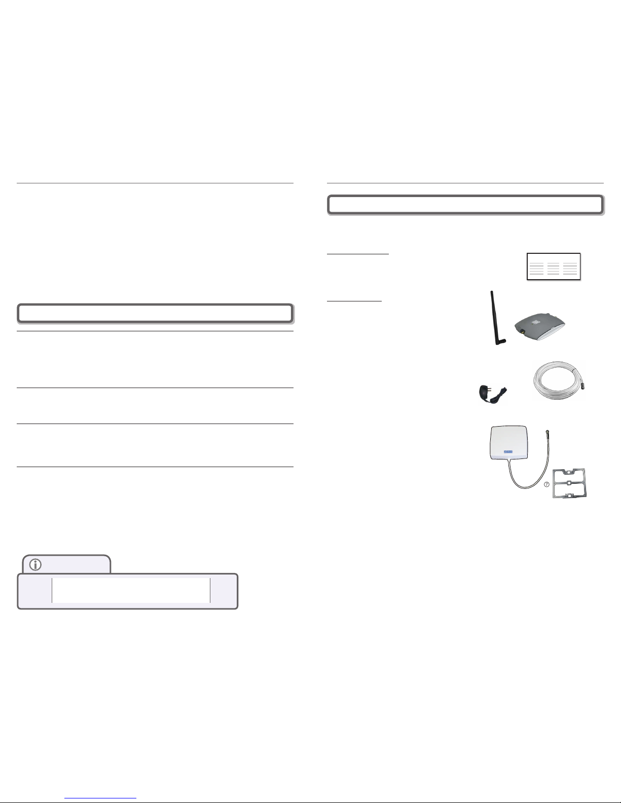
Package Contents: zBoost SOHO YX560P
⑦
③
④
⑤
⑥
Before you begin, make sure all of the following parts came with your zBoost SOHO YX560P
Literature Contents:
① Set-up overview for zBoost SOHO YX560P
(User Guide online only)
Product Contents:
② zBoost Base Unit
③ Base Unit Antenna
④ Power Supply
⑤ RG-6 Coax Cable, 50 feet
⑥ Signal Antenna
⑦ Signal Antenna Mounting Hardware
Cet appareillage numérique de la classe [B] répond à toutes les exigences de l’interférence
canadienne causant des règlements d’équipement. L’opération est sujette aux deux conditions
suivantes: (1) ce dispositif peut ne pas causer l’interférence nocive, et (2) ce dispositif doit accepter
n’importe quelle interférence reçue, y compris l’interférence qui peut causer l’opération peu désirée.
Le fabricant nominale de la puissance de sortie de ce matériel est simple transporteur. Pour les
situations lorsque plusieurs signauxporteurs sont présents, l’évaluation devrait être réduite de
3.5 dB, en particulier lorsque le signal de sortie est ré-émise et peut provoquer des interférences
adjacentes à la bande utilisateurs. Ce pouvoir est de la réduction par le biais de la sortie
d’alimentation ou la réduction de gain et non par un atténuateur à la sortie du dispositif.
Please note: This unit has been approved for use in Canada under RSS 131, however, consent
for the use of this device to improve cellular or PCS coverage, must be obtained through your
cellular or PCS provider, prior to placing the unit in operation. Please refer to the Industry Canada
document CPC 2-1-05, Section 6.1 available or viewable at:
http://www.ic.gc.ca/epic/site/smt-gst.nsf/en/sf08942e.html
Copyright Notice
This manual is copyrighted. All rights reserved. This manual, whole or in part, may not be copied,
photocopied, reproduced, translated or reduced to any electronic medium or machine readable
form for distribution. This manual whole or in part, may not be modied without prior consent, in
writing, from Wireless Extenders.
Copyright © 2012 by Wireless Extenders, Inc.
Trademarks
Wireless Extenders, Wi-Ex, the Wi-Ex logo, zBoost, the zBoost logo and Extending Cell Zones are
registered trademarks of Wireless Extenders, Inc.
Safety Guidelines
In accordance with FCC requirements of human exposure to radiofrequency elds, the radiating
element (antenna) shall be positioned such that a minimum separation distance of 8 inches (20cm)
is maintained between the radiating element and the user and/or general population.
Limited Liability
In no event shall Wireless Extenders be liable for any direct, indirect, special, punitive, incidental,
exemplary or c onsequential damages, or any damages, whether in an action under contract ,
negligenc e, or any other theory, arising out of or in connecti on with the set up of, use of, inability
to use, or performance of t he informati on, services, produc ts, and materials available fro m this
manual. These limitations shall apply notwithstanding any failure of essential purpose of any
limited remedy. Because some jurisdictions do not allow limit ations on how long an implied
warranty last, or the exclusion or limitation of liability for consequential or incid ental damages, the
above limitations may not apply to you.
For full warranty guideline s, see page 13
Safety and Product Warranty Information
②
Note
Change s or mo dicat ions not expr essly approve d by
Wi-Ex® could void t he user’s au thorit y to op erate this
equipm ent and /or vo id the produc t warr anty.
SETUP OVERVIEW
①
zBOOST® SOHO YX560P USER GUIDE
iv
zBOOST® SOHO YX560P USER GUIDE
1
Optional zBoost Accessories Table of Contents
FCC In formati on ......... ...... ....... ...... ...... ....... ...... ....... ...... ...... ....... ...... ....... ...... ...... ....... ...... ....... ......i
Indust ry Cana da Reg ulations ........ ....... ...... ....... ...... ...... ....... ...... ....... ...... ...... ....... ...... ....... ...... ......i
Safety and Pr oduct Warranty Inform ation ........ ............. ...... ....... ...... ............. ...... ....... ...... ............ ii
Copyri ght Not ice ... ....... ...... ............. ...... ....... ...... ............. ...... ....... ...... ............. ...... ....... ...... ..........ii
Trademar ks ....... ...... ...... ....... ...... ....... ...... ...... ....... ...... ....... ...... ...... ....... ...... ....... ...... ...... ....... ...... ..ii
Safety Guidel ines ........... ...... ............. ...... ....... ...... ............. ...... ....... ...... ............. ...... ....... ...... ........ii
Limite d Liabi lity ..... ....... ...... ............. ...... ....... ...... ............. ...... ....... ...... ............. ...... ....... ...... ..........ii
Packag e Conte nts: z Boost SOHO YX5 60P ...... ....... ...... ............. ...... ....... ...... ............. ...... ....... .... iii
Option al zBoo st Acces sories ........ ...... ....... ...... ....... ...... ...... ....... ...... ....... ...... ...... ....... ...... ....... .... iv
Table of C ontent s ............... ...... ....... ...... ............. ...... ....... ...... ............. ...... ....... ...... ............. ...... ..... 1
Overvi ew ........... ...... ............. ...... ....... ...... ............. ...... ....... ...... ............. ...... ....... ...... ............. ...... .... 2
Why In door Si gnals Can Be Weak ......... ...... ............. ...... ....... ...... ............. ...... ....... ...... ............. ... 2
Prepar ing to Set Up Your zBoos t Product ........... ...... ....... ...... ............. ...... ....... ...... ............. ...... ... 3
Check for Sig nal St rength ........ ...... ....... ...... ...... ....... ...... ....... ...... ...... ....... ...... ....... ...... ...... ....... ... 3
Tools Needed ............. ...... ....... ...... ............. ...... ....... ...... ............. ...... ....... ...... ............. ...... ....... .... 3
Import ant: Be fore i nstalling, pl ease n ote the se imp ortant factor s in d etermin ing pe rformance ..... 4
Determ ine the Neede d Coverage Area ........ ............. ...... ....... ...... ............. ...... ....... ...... ............. ... 4
Additi onal Ca ble Re quirements ........ ............. ...... ....... ...... ............. ...... ....... ...... ............. ...... ....... . 5
Ground ing the Signa l Antenna ............ ...... ....... ...... ....... ...... ...... ....... ...... ....... ...... ...... ....... ...... ...... 5
Securi ng Cabl e with a Drip Loop ...... ............. ...... ....... ...... ............. ...... ....... ...... ............. ...... ....... . 5
Power Require ments ........... ....... ...... ............. ...... ....... ...... ............. ...... ....... ...... ............. ...... ....... . 5
Settin g Up Your z Boost S ignal Booster ......... ....... ...... ............. ...... ....... ...... ............. ...... ....... ...... . 6
FIRST: Mount the S ignal Ant enna ......... ...... ....... ...... ............. ...... ....... ...... ............. ...... ....... ...... .... 6
SECOND : Posit ion th e Base Unit ........ ...... ....... ...... ............. ...... ....... ...... ............. ...... ....... ...... ..... 6
THIRD: Run th e coax ial cable bet ween t he Base Unit and Signal Anten na ......... ...... ...... ....... ...... 7
FOURTH: Connec t the zBoost Base U nit to the po wer su pply a nd plug into an outl et ............ ..... 7
FIFTH: Antenna Aim ing ....... ....... ...... ............. ...... ....... ...... ............. ...... ....... ...... ............. ...... ....... . 8
Conrm That Your zB oost is Workin g Prop erly ..... ....... ...... ............. ...... ....... ...... ............. ...... ....... 8
Improv ing Your Co verage Ar ea .......... ...... ............. ...... ....... ...... ............. ...... ....... ...... ............. ...... .. 9
zBoost Base U nit Li ght Indicator s ............ ...... ....... ...... ...... ....... ...... ....... ...... ...... ....... ...... ....... ..... 10
Technical Speci cations ...... ...... ....... ...... ...... ....... ...... ....... ...... ...... ....... ...... ....... ...... ...... ....... ...... ..11
Freque ntly Aske d Ques tions ... ...... ...... ....... ...... ....... ...... ...... ....... ...... ....... ...... ...... ....... ...... ....... ... 12
Warranty Inform ation ......... ...... ....... ...... ............. ...... ....... ...... ............. ...... ....... ...... ............. ...... ... 13
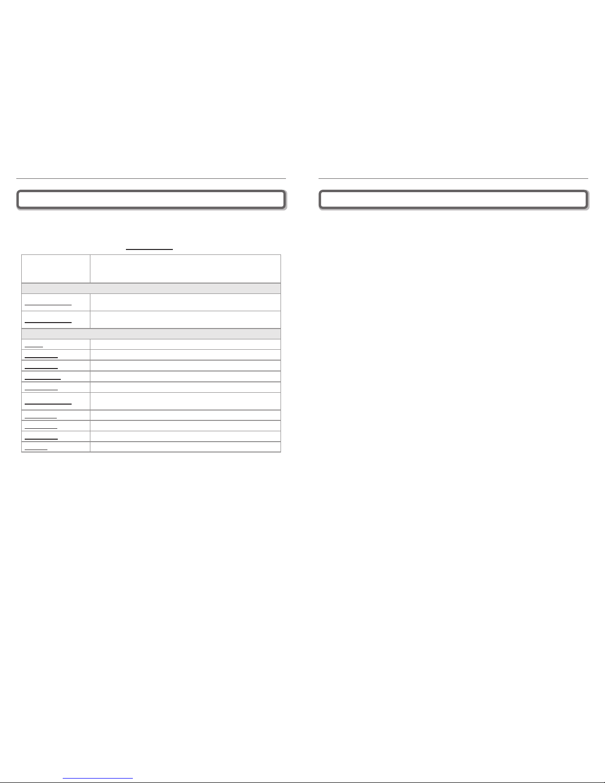
The following accessories are available to improve signal reception and provide increased coverage
in your home or ofce. Please see our website for complete selection.
To order, call 1-800-871-1612 or visit, www.Wi-Ex.com
Part # Description
Most Popular Accessories
YX039-PCS-CEL
Bi-Directional receiving Signal Antenna upgrade
(13 dBi PCS / 8 dBi CEL)
YX027-PCS-CEL
Directional transmitting Base Unit Antenna upgrade
(9 dBi PCS / 6 dBi CEL)
Other Accessories:
YX012 Outside Grounding Kit
YX030-15W 15 ft coax extension cable, RG-6
YX030-35W 35 ft coax extension cable, RG-6
YX031-100W 100 ft coax extension cable, RG-11
YX030-08W 8 inch at window entry cable
YX050-PCS-CEL
Omni-Directional transmitting ceiling-mount Base Unit Antenna
(2 dBi PCS / 1 dBi CEL)
CANT-0041
YX026-CEL Directional receiving Signal Antenna upgrade (11 dBi)
YX023-PCS Directional receiving Signal Antenna upgrade (13 dBi)
YX015D PCS-CEL Antenna Combiner
 Loading...