

Page 1

User Manual
Published May 2019
Firmware Version URX-057
URX100
1
Page 2

FRONT ...................................................................................................................................................................... 4
T
OP .......................................................................................................................................................................... 5
R
EAR ........................................................................................................................................................................ 6
HOME SCREEN .................................................................................................................................. 7
MAIN MENU ..................................................................................................................................... 8
N
AVIGATING THE MAIN MENU ..................................................................................................................................... 8
F
REQUENCY SELECT ..................................................................................................................................................... 8
W
ALKIE IN GAIN ......................................................................................................................................................... 8
OCK SCREEN ............................................................................................................................................................. 8
L
SUB MENUS ...................................................................................................................................... 9
M
ENU GROUPS .......................................................................................................................................................... 9
A
CCESSING AND NAVIGATING THE MENU GROUPS ............................................................................................................ 9
E
NTERING AND NAVIGATING A SUB MENU ....................................................................................................................... 9
E
XITING THE EXTENDED MENU ...................................................................................................................................... 9
CHANNEL PRESET MENU ................................................................................................................. 10
N
UMBER OF PRESETS ................................................................................................................................................ 10
P
RESET ADJUST ........................................................................................................................................................ 10
SCAN MENU ................................................................................................................................... 11
F
REQUENCY SCAN ..................................................................................................................................................... 11
Scanning for a frequency ................................................................................................................................. 11
Selecting the frequency ................................................................................................................................... 11
S
ETTING THE SCAN RANGE ......................................................................................................................................... 12
ROUTING MENU ............................................................................................................................. 13
W
ALKIE ROUTING ..................................................................................................................................................... 13
ECEIVE AUDIO LEFT ROUTING ................................................................................................................................... 13
R
R
ECEIVE AUDIO RIGHT ROUTING ................................................................................................................................. 13
TIME CODE MENU .......................................................................................................................... 14
M
UTE TIME CODE UNTIL JAMMED .............................................................................................................................. 14
T
IME CODE OUTPUT LEVEL ......................................................................................................................................... 14
SETUP MENU .................................................................................................................................. 15
T
ONE OUTPUT ......................................................................................................................................................... 15
M
ODULATION SELECT................................................................................................................................................ 15
M
UTE IF UNIT CODE ................................................................................................................................................. 15
S
OFTWARE UPDATE .................................................................................................................................................. 16
IFB
VOTING ............................................................................................................................................................. 16
A
UDIO DELAY SET ..................................................................................................................................................... 16
D
ISPLAY FLIP ............................................................................................................................................................ 16
ATTERY TYPE .......................................................................................................................................................... 16
B
OLED
BRIGHTNESS ................................................................................................................................................... 17
I
NFORMATION PAGE ................................................................................................................................................. 17
H
IDE ENCRYPTION MENU .......................................................................................................................................... 17
E
NCRYPTION CODE SET .............................................................................................................................................. 17
Adjusting the encryption code ......................................................................................................................... 17
2
Page 3

WIRING CONFIGURATION ............................................................................................................... 18
TA5
CONNECTOR ..................................................................................................................................................... 18
H
EADPHONE OUT ..................................................................................................................................................... 18
OPERATING FREQUENCIES .............................................................................................................. 19
UHF
AUDIO ............................................................................................................................................................. 19
ANTENNA CUTTING CHART ............................................................................................................. 20
FIRMWARE ..................................................................................................................................... 21
SPECIFICATIONS.............................................................................................................................. 22
PRODUCT SUPPORT ........................................................................................................................ 23
ZAXCOM WARRANTY POLICY AND LIMITATIONS ............................................................................. 24
3
Page 4
2
1
3
2 1 4
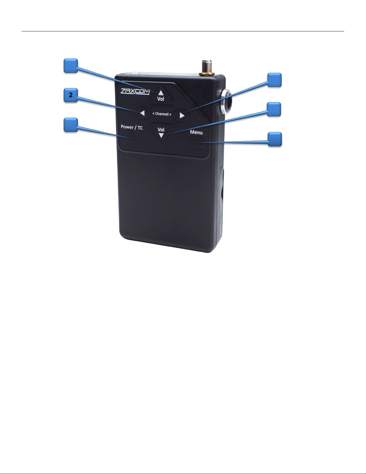
Zaxcom URX100 Front
Front
1. Volume Up and Down keys
2. Channel Up and Down keys
• When in the home or lock screen press to cycle through channel presets.
• When in the sub menu press to cycle through the menus.
• When in a menu press the keys to change the menu parameters.
3. Power / Time Code key
• Press and hold for 2 seconds to power up the URX100.
• Press and hold for 4 seconds to power down the URX100 - then pess the MENU key
• Press three times quickly to enter or exit the menu groups.
• From the home or lock screen press to display the time code and user bits.
4. Menu key
• Press to cycle to the next menu item.
4
Page 5
3
1
2
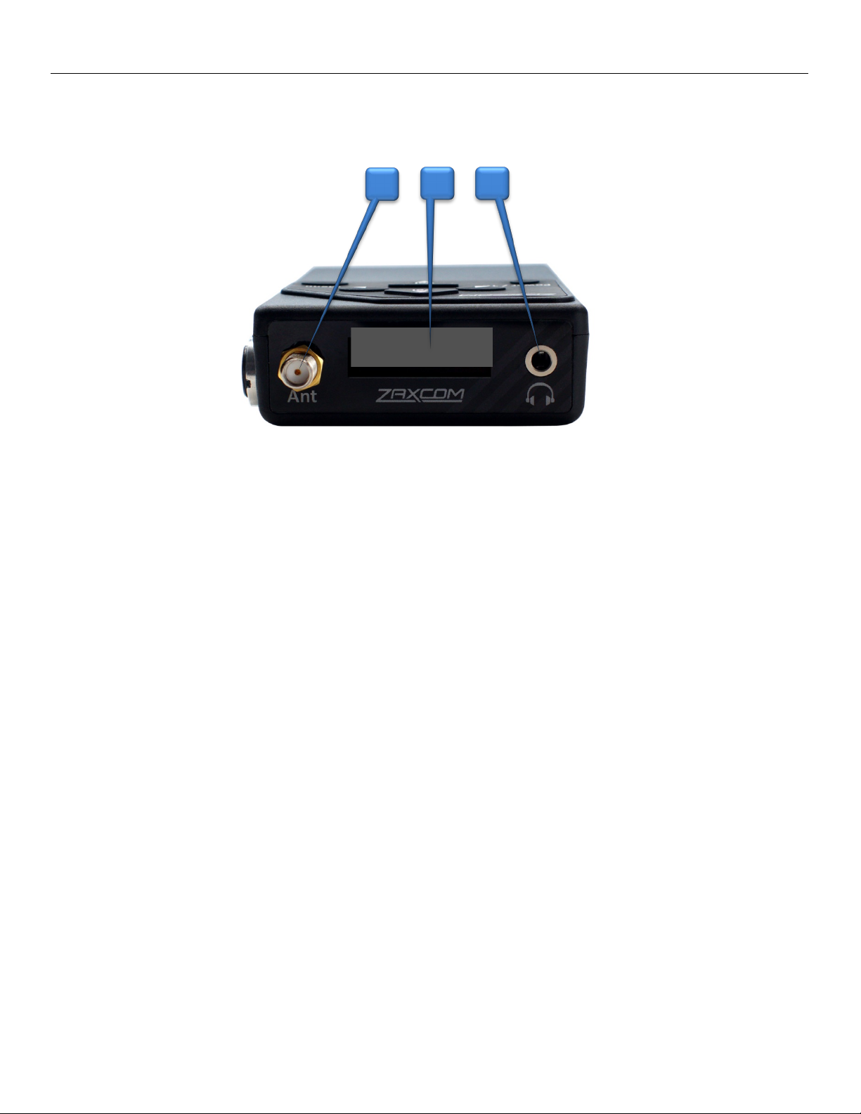
Zaxcom URX100 Top
Top
1. SMA Antenna Connection
2. OLED Display
3. 3.5mm Headphone Jack / URXL1 connector
Please note that this jack acts as the second antenna for diversity reception.
For optimal preformance when a headphone, or the URXL1 lanyard, is not being used it is
recommended that a 3.5mm connector with a piece of wire (approximatally 5 inches long)
connected to the sheild is inserted to act as a second antenna.
5
Page 6
1
2
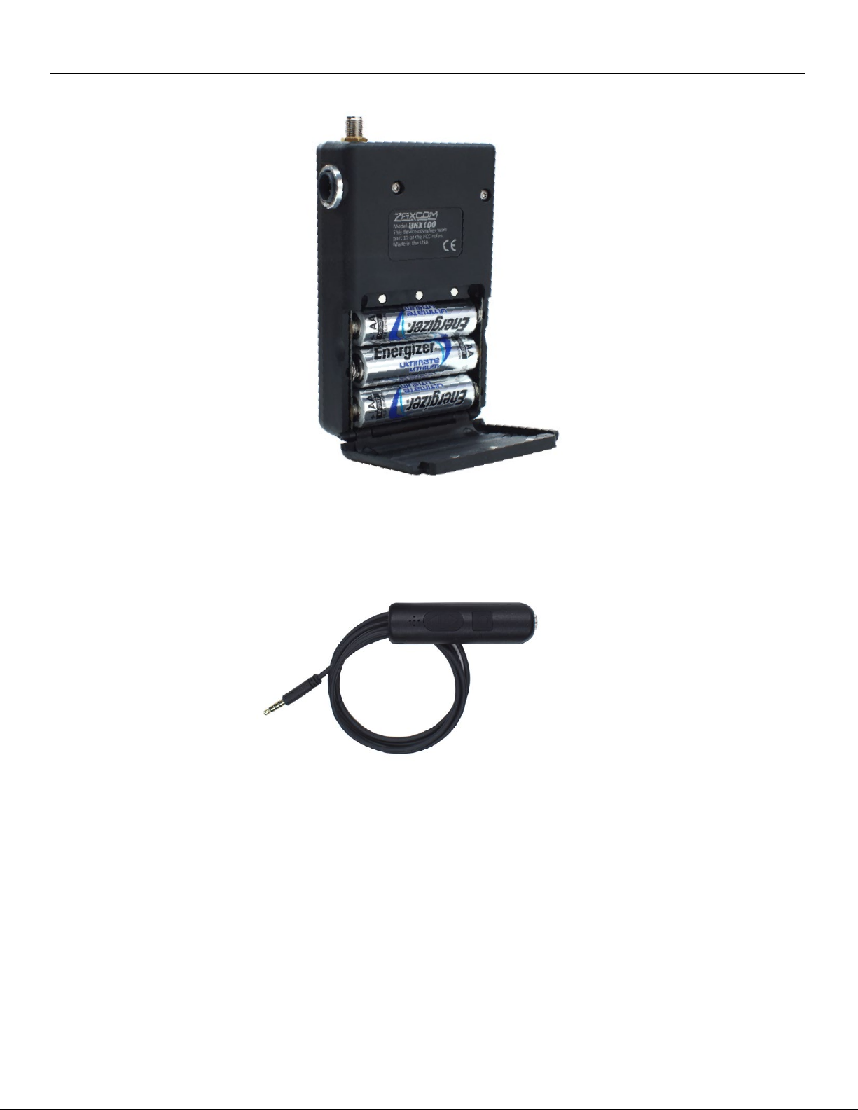
Zaxcom URX100 Rear
Rear
1. Battery Compartment - The URX100 uses 3 AA batteries and will work with alkaline, NiMH or
lithium AA batteries.
2. URXL1 Walkie Talkie Lanyard (Optional)-The URX100 can be connected to the remote speaker/mic
port of a walkie talkie. Allowing the user to route the walkie talkie audio left right or center and mix
it with the URX100 audio so both the walkie and URX100 audio can be heard at the same time with
a single pair of headphones.
The URXL1 Lanyard has a push-to-talk button and a microphone to communicate with the walkie
talkie. Any headphone with a 3.5mm jack can be plugged into the URXL1.
6
Page 7
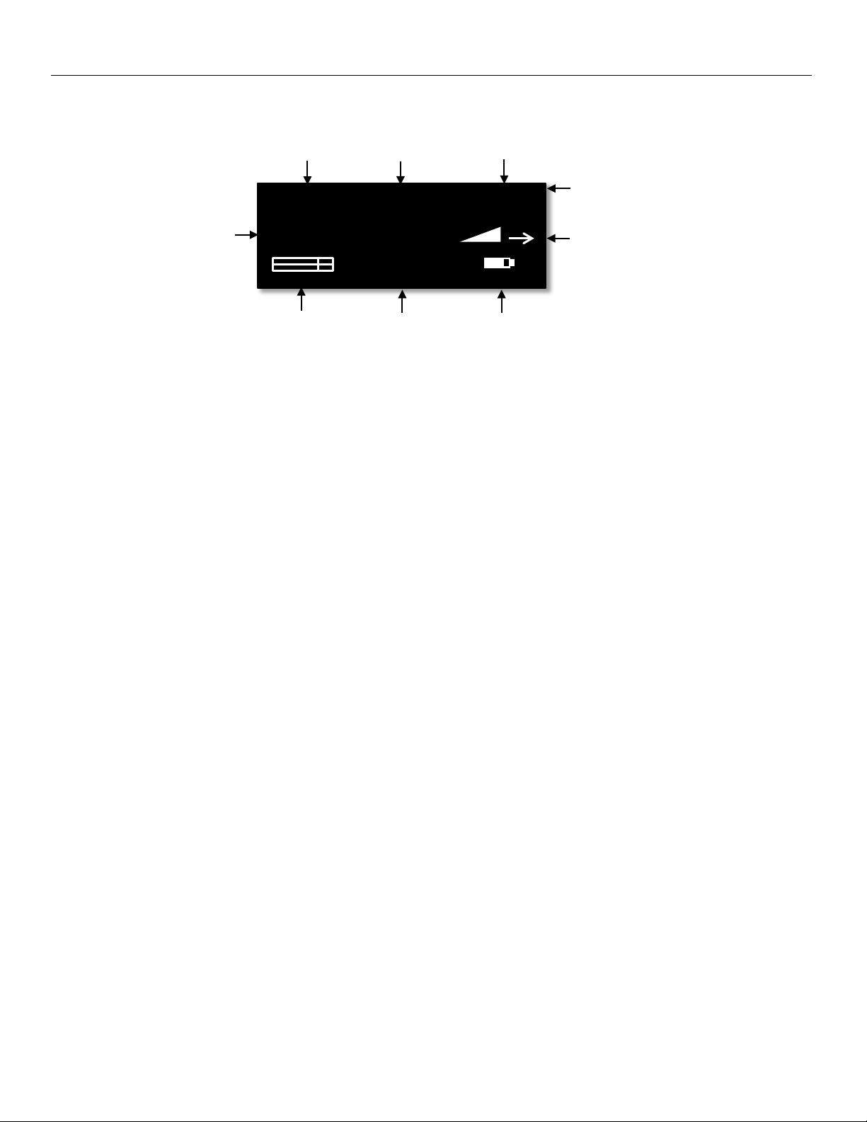
Zaxcom URX100 Home Screen
Audio Level Meter TC Battery Meter
TX NAME REC TXBATT
Home Screen
Received TX Name Rec Status Low Battery Indicator
Save Indicator
Received RF Signal Strength Meter
Frequency Receiving Antenna
(P1) 570.1
09:18:05:03
Received Transmitter Name
This is the name of the transmitter being received by the URX100.
Received Transmitter Record Status
This displays the status of the internal recorder of the transmitter being received by the URX100. Stop (STP) Play (PLY) or Record (REC) will be displayed.
Low Battery Indicator of Received Transmitter
TX BATT will appear when the battery level of the transmitter being received is low.
Save Indicator
The save indicator will briefly flash when after a setting change as a parameter is being written to the memory
of the URX100. .
Received Frequency
This is the preset position number and the UHF frequency that the URX100 is receiving.
RF Signal Strength
The RF strength meter shows the radio signal strength of the transmitter. The RF signal is depicted as a staircase
pattern with the lowest step (low signal strength) on the left and building up to the right (higher signal strength).
When more stairs are showing the stronger the signal is.
Receiving Antenna
This shows the antenna that is receiving the RF signal.
Audio Level
Displays the incoming audio level, the meter extends from the left to the right. The vertical bar is the -20dBFS
mark and the far right side of the box is 0dBFS.
Time Code
This is the time code of the transmitter that the URX100 is receiving.
Battery Meter
This displays a rough indication of the transmitter’s battery level. For a more accurate battery reading the battery
type being used in the transmitter needs to be set in the setup menu.
7
Page 8
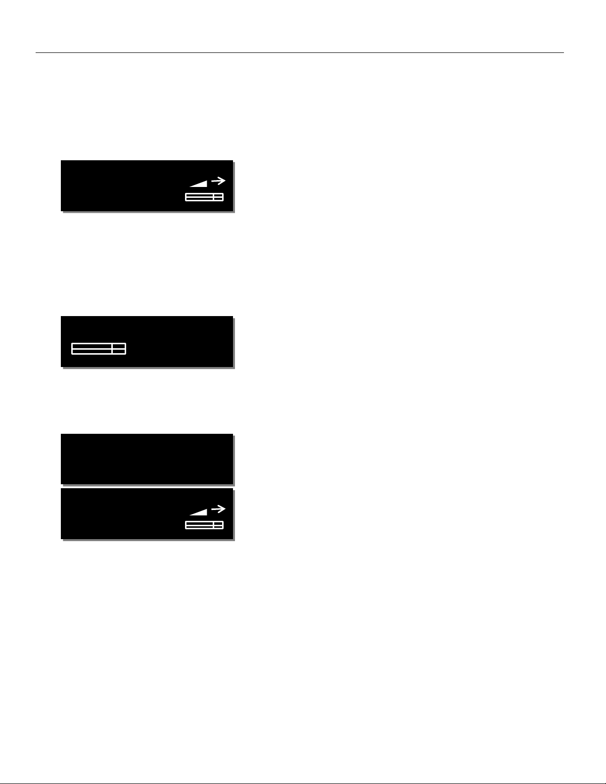
Zaxcom URX100 Main Menu
WALKIE IN GAIN:
60
FREQ: 570.0
LOCKING IN 4
FREQ: 570.0
Main Menu
Navigating the Main Menu
• To enter the main menu - press the MENU key.
• To advance to the next menu press the MENU key again.
Frequency Select
STEREO ‘TX NAME’
The frequency select menu is where the URX100 receive frequency is set. This frequency needs to match the
frequency that is set on the corresponding transmitter. To adjust the frequency press the channel up key to
increase the frequency and press the channel down key to decrease the frequency. Also displayed is the
modulation format, the name of the transmitter being received, a signal strength meter and audio meter and an
arrow showing which antenna the signal is being received on.
Walkie In Gain
6
The walkie in gain menu is where the level of the optional lanyard microphone input from to the URX100 is set.
The higher the level is set the more gain the microphone will have.
Lock Screen
6
STEREO ‘TX NAME’
The lock screen is landed on a 5 second countdown clock will start. After 5 seconds elapse the URX100 will lock
and the menus cannot be accessed. This is to prevent the parameters from accidentally be changed.
When the URX100 is locked the volume adjust keys, the channel preset keys and the time code display key can
still be used.
To exit the lock screen hold the MENU key and press the CH UP key 4 times.
8
Page 9

Zaxcom URX100 Menu Navigation
Sub Menus
Menu groups
The URX100 has five sub menu groups
• Channel Preset - Sets the number of preset channels, and sets the frequency of each preset channel.
• Scan - Is where the URX100 can scan the set RF spectrum.
• Routing - Sets the routing of the received audio and the walkie feed to the desired headphone side.
• Time Code - Changes the time code parameters of URX100.
• Setup - Changes the parameters of the general operation on the URX100.
Accessing and navigating the menu groups
From in the main menu press the POWER / TC key three times quickly to access the six menu groups. Then
pressing the CH UP or CH DOWN key will cycle between the menu items.
Entering and navigating a sub menu
When landing on the desired menu group press the MENU key to enter that menu. Pressing the MENU key
again will cycle through the menu items.
To return to the top of the menu press the MENU key to cycle to the top or press and hold the MENU key for
1.5 seconds.
Exiting the extended menu
To exit the menus press the POWER / TC key 3 times quickly to return to the main menu.
9
Page 10

Zaxcom URX100 Frequency Presets
NUMBER OF
PRESET 2: 524.3
CHANNEL PRESET MENU
Number of Presets
PRESETS: 100
From this menu the number of presets that the URX100 will display can be selected. The URX100 can display up
to 100 presets.
Preset Adjust
TX NAME (ON)
From this menu each preset frequency can be adjusted by pressing the CH UP and CH DOWN keys. If the
frequency has a corresponding transmitter that is on the name of the transmitter will be displayed.
Each preset can be toggled on and off by pressing the POWER/TC key. When the preset is ON the user will be
able to cycle to that preset and listen to it, if the preset is OFF the user will not be able access that preset.
After the frequency is set press the MENU key to advance to the next preset.
Please note the number of available frequencies will be determined by the number of presets that was set in the
previous menu.
10
Page 11

Zaxcom URX100 Scan Menu
PRESS TO SCAN
SCANNING 568.9
SCAN MENU
Frequency Scan
(ALL 200: 512 – 698)
The frequency scan menu is where the URX100 can scan the user specified frequency range and search for a
clear frequencies. The frequency range will be displayed on the bottom half of the display.
After the scan is completed a graphic display of the RF that is present in that specified range will be shown and
the URX100 will also suggest a clear frequency. That frequency can be accepted by pressing the CH UP key. Or
press the CH DOWN key to skip the first chosen frequency and have the URX100 suggest another frequency.
Scanning for a frequency
• Turn off the transmitter(s).
• From the scan menu press the CH UP key to initiate a scan.
• While the URX100 is scanning, the frequency being examined is
displayed in the bottom half of the screen. Once the scan has
completed a graphic map of the scan will be displayed. The low end of the frequency range is on
the left side and the high end is on the right. Wherever RF is found, a vertical line will be drawn.
The line extends from the baseline up. The length of the line indicates the level or strength of the
found RF at that frequency.
Selecting the frequency
When the scan is complete the URX100 will draw a vertical blinking
line on the display to indicate where the first suggested frequency is,
and the frequency in MHz will appear below the scan graphic.
• Press the CH UP key to accept the new frequency.
• Press the CH DOWN key to decline and suggest a different frequency.
11
Page 12

Zaxcom URX100 Scan Menu
SCAN LIMIT:
ALL 200 512 - 698
Setting the Scan Range
The scan range menu sets the frequency range that the URX100 will scan when doing a frequency scan. Pressing
the CH UP and CH DOWN keys will cycle through the scanning options.
Available Scan Ranges
• All 200 - All frequencies from 512.0MHz through 698.0MHz will be scanned..
• LO 100 - Corresponds to the frequency range of 3.5 transmitters, when selected the RX200 will scan all
frequencies from 512.0MHz through 614.0MHz.
• HI 100 - Corresponds to the frequency range of 3.6 transmitters, when selected the RX200 will scan all
frequencies from 596.0 through 698.0MHz.
• BLK (20 -26) - Allows the RX200 to scan a specific block (Blocks 20-26).
• Block 20 - 518-542 MHz
• Block 21 - 536-572 MHz
• Block 22 - 560-590 MHz
• Block 23 - 590-614MHz (block 23 needs to be enabled)
• Block 24 - 614-644 MHz
• Block 25 - 638-668 MHz
• Block 26 - 662-698 MHz
12
Page 13

Zaxcom URX100 Headphone Routing Menu
WALKIE ROUTED
RX LEFT ROUTED
RX RIGHT ROUTED
ROUTING MENU
Walkie Routing
TO HP-BOTH
From the walkie routing menu the walkie receive audio can be routed to the desired headphone side.
The walkie audio can be routed to both sides of the headphones, the left side only, the right side only, or it can
be disabled.
Receive Audio Left Routing
TO HP-LEFT
From the RX left routing menu the left received audio can be routed to the desired headphone side.
The audio can be routed to both sides of the headphones, the left side only, the right side only, or it can be
disabled.
Receive Audio Right Routing
TO HP-RIGHT
From the RX right routing menu the right received audio can be routed to the desired headphone side.
The audio can be routed to both sides of the headphones, the left side only, the right side only, or it can be
disabled.
13
Page 14

Zaxcom URX100 Time Code Menu
TC OUTPUT LEVEL:
MUTE TC UNTIL
TIME CODE MENU
Mute Time Code Until Jammed
JAMMED: ON
If mute time code is set to on, the time code out of the TA5 is muted and the URX100 will not output any time
code until it receives and locks to the time code that is being sent from the transmitter. This is to prevent
incorrect time code being outputted.
Time Code Output Level
1.000 VOLTS
The URX100’s time code output can be adjusted for equipment that needs a specific time code voltage.
The URX100 can output time code from 0.001 to 3.000 Volts.
14
Page 15

Zaxcom URX100 Set Up Menu
MUTE IF UNIT CODE
(NEVER MUTE)
TONE :
OFF
RX FORMAT:
MUTE IF UNIT CODE
SETUP MENU
Tone Output
The tone menu allows the URX100 to output tone. This is useful to set levels and check routing. Pressing
the CH UP and CH DOWN keys key will cycle through and output the different tone settings.
• OFF - No tone is being outputted.
• -20dBFS -Tone is outputted at -20dBFS.
• +0dBFS - Tone is outputted at full scale 0dBFS.
Modulation Select
STEREO
The modulation menu is where the receive format is set. Modulation is simply the way a transmitter
“modulates”, or sends, its signal to the URX100. This setting needs to match the modulation mode that the
corresponding transmitter is set to - if the two setting do not match the URX100 will not be able to receive and
decode the signal from the transmitter.
Modulation types
• STEREO - Select when receiving audio from a Camera Link, Maxx transmitter, or a stereo transmitter.
• ZHD 96 - Select when receiving signal from a ZHD transmitter set to ZHD-96.
• XR MONO - Select when using extended range modulation (XR).
• MONO - Select when using a mono transmitter and XR modulation is not available in the software.
• EU - Select when using a transmitter that is set up for European broadcast standards.
Mute If Unit Code
IS LESS THAN 2
This menu sets if transmitters with certain ZaxNet unit codes will not be able to be monitored by the URX100.
For example if this menu is set to 30 any transmitter with a ZaxNet unit code below 30 will not be able to be
monitored by the URX100.
If a muted preset is selected to be monitored “MUTE” will appear on the display and that preset will not be able
to be listened to - even if that preset is enabled.
15
Page 16

Zaxcom URX100 Set Up Menu
DISPLAY FLIP:
PRESS TO
IFB VOTING: ON
AUDIO DELAY:
BATTERY TYPE:
Software Update
UPDATE SOFTWARE
This menu is where the URX software is updated from.
When in this menu pressing the CH UP key will initiate the update process and the URX100 will wait and search
for software that will be transmitted from a Zaxcom transmitter (please refer to the software update section of
this manual for more information on how to update the URX100.)
IFB voting
200KHZ OFFSET
The IFB voting feature will allow the URX100 to automatically switch to a secondary frequency when it loses its
signal from the primary transmitter. One purpose of this is, on a large set, a second transmitter can be placed
at a distant location, so if the URX100 loses the signal from one transmitter it will automatically switch to the
other transmitter.
To use IFB voting just set the offset in this menu to (200 KHz, 300 KHz, 400 KHz or 500 KHz). Then set the
second transmitters frequency to the primary frequency + the offset. So for example if the primary frequency
is 560.000 MHz and the offset is 200 KHz then the second transmitter should be set to 560.200 MHz
Audio Delay Set
OFF
The audio delay menu sets a variable delay to the output audio. A delay is useful if the ERX is being used for
personal monitoring and there is a video processing delay to the monitors - so engaging the delay will delay the
audio to match the video. The audio delay can be adjusted from 1MS to 400MS in 1MS increments.
Display Flip
OFF
The display flip menu changes the orientation of the display for when the unit will be inverted.
Battery Type
LITHIUM
The chemistry of the batteries being used in the URX100 is selected in this menu. Alkaline, NiMH or Lithium can
be selected
16
Page 17

Zaxcom URX100 Set Up Menu
ENCRYPTION MENU:
HIDDEN
ENCRYPTION CODE
OLED BRIGHTNESS:
- - - INFO - - -
URX-100
OLED Brightness
3
The OLED brightness menu adjusts the brightness of the OLED display. The brightness can be adjusted from 0 to
3 with 0 being the dimmest setting and 3 being the brightest.
Information Page
FIRMWARE 0-53
SN: 1234
This page displays the current firmware version and the serial number of the URX100.
Hide Encryption Menu
This menu allows for the encryption menu to be hidden preventing accidental changes.
• HIDDEN - The encryption menu does not appear when cycling through the menu settings.
• SHOW - The encryption menu will appear.
Encryption Code Set
ID1: 000 ID0: 000
This menu is where the encryption is turned on and the code is set. This code needs to match the encryption
code of the associated transmitter(s). If an encryption code is set on the transmitter the transmitted audio will
be encrypted and can only be listened to if the URX100 has the same matching encryption code entered. When
the codes do not match, all that will be heard is white-noise.
These two sets of numbers are formed into a single six-digit encryption code which provides a total of
16,777,216 possible combinations
Adjusting the encryption code
1. Press the menu key to cycle to the next character.
2. To change the designated character, press the CH UP or CH DOWN key.
3. To exit this page, press and hold the MENU key.
. For non-encrypted operations all six numbers should be set to 0.
17
Page 18

Zaxcom URX100 Wiring Configuration
Wiring Configuration
TA5 Connector
Pin
1 - Ground
2 - Audio in from walkie receiver
3 - Time Code out and AUX PTT (open collector)
4 - Microphone audio out to walkie with PTT bias control
5 - IFB audio out (Hard-wired to headphone left feed)
Headphone Out
The headphone out is a 3.5mm TRRS connector. The URXL1 walkie lanyard uses all 4 connectors, but any standard
headphone can be used to listen to audio.
Please note that the when a headphone, or the optional URXL1 Lanyard, is being used its wire becomes the second
antenna for the URX100 giving it diversity reception. It is recommended that when no headphone, or lanyard, is
connected to the 3.5mm jack a 3.5mm plug with a short piece of cable (approximately 5 inches long - wired only to
the shield) should be connected for better reception.
18
Page 19

Zaxcom URX100 Operating Frequencies
Operating Frequencies
UHF Audio
512.0 MHz to 698.0 MHz (Blocks 20 through 26)
19
Page 20

Zaxcom URX100 Antenna Cutting Chart
Antenna Cutting Chart
20
Page 21

Zaxcom URX100 Firmware Update
Firmware
Updating the URX100 firmware using a Zaxcom transmitter
1. Format a micro SD card in the programing transmitter.
2. With a computer take the formatted card and perform the following:
• Delete the “DELETE.ME” file from the card.
• Download the new URX100 firmware from the Zaxcom website and load it into the card (URX-XXX.BIN).
https://zaxcom.com/support/updates/
3. At the URX100 (please note multiple URX100’s can updated at a time):
• Verify that the batteries in each URX100 has sufficient battery power.
• Verify the modulation mode is set to mono.
• Verify encryption is off (ID1 and ID0 are both set to 000)
• Set the UHF Frequency to the same frequency as the programming transmitter.
• Proceed to the software update page in the setup menu and press the CH UP key.
• “WAITING FOR PROGRAM” will be displayed - this indicates that the URX100 is ready to receive the new
software.
• Place the URX100 within 10’ and line-of-sight of the programming transmitter. All of the units should
remain motionless to insure they receive a strong and undisturbed signal.
4. At the programing transmitter:
• Insert the card with the BIN file.
• Verify that transmitter has sufficient battery power.
• Verify the modulation mode is set to mono.
• Verify encryption is off (ID1 and ID0 are both set to 000)
• Set the UHF Frequency to the same frequency as the URX100 is set to.
• Start the software transmission. Please Refer to the specific transmitter manual for instructions on how to
transmit the software to the receiver (QRX / RX200)
• The transmitter will indicate that it found the program on the card and that it has started sending it.
Please note the transmit process will cycle over and over until manually stopped.
5. Each URX100 should indicate it is receiving the software.
6. The programing transmitter will automatically resend the software until it is manually stopped. So f there is
a reception error, the URX100 will automatically restart the update process with the start of the next cycle.
7. When the URX100 is done updating the software “SUCCESS . . . PRESS TC TO REBOOT” will be displayed.
Please note that it is very important that the URX100 is not powered down before this is displayed.
8. It is now safe to stop the firmware transmission.
9. At each URX100 press the POWER / TC key and verify that the URX100 is running the new software.
WARNING: After the URX100 has received its entire program, it will erase and burn its firmware into its ROM.
During this process, which will take about a minute, DO NOT turn off the URX100.
When “SUCCESS . . . PRESS TC TO REBOOT NOW” is displayed it is safe to reboot the URX100.
If the program is never fully received, it is safe to cycle the power.
Please note the following transmitters can update the URX100:
ZHD transmitter running firmware version THD-275A or THD-286 or higher.
TRXCL3 Camera Link running firmware version CL-286 or higher.
ZMT transmitter running version firmware version ZMT-285 or higher.
21
Page 22

Zaxcom URX100 Specifications
Specifications
Receiver
Receiver RF Channels: 1
Diversity method: antenna switching
RF Modulation: proprietary digital method
RF Frequency Range: 512 to 698 MHz
RF Frequency Step: 100 KHz
RF Signal Bandwidth: 200 KHz
Channel Separation: 500 KHz (700 KHz recommended)
Sensitivity: -114 dBm
Antenna Connector: 50-ohm SMA female
Receiver Audio
Analog Output
Dynamic Range: 110 dB
Distortion: 0.002%
Frequency Range: 20Hz to 16 kHz
DAC Bit-depth: 24 bits
Connector: TA-5M
Audio Output
Impedance: 16 ohms
Output Power: 100 mW
Output Type: Headphone driver
Output connector: 3.5 mm
Mode: 2-Channel unbalanced or 1-Channel balanced
Max Output Level: +12 dBm
Timecode
Timecode output connector: TA5 Male
Timecode output level: .01VPP – 3VPP Variable
Time code output rate: 23.98, 24, 25, 29.97 NDF, 29.97 DF, 30
TA5 Auxiliary Connector
Timecode output, Left audio out, Walkie Microphone out, Walkie Audio return
Power
Internal Power: 3 AA Batteries
Li-Ion Battery Life: Up to 11 hours
NiMH Battery Life: Up to 9 hours
Alkaline Battery life: Up to 7 hours
*these times are approximate and will be refined as more testing is done*
Misc.
TA5 Auxiliary Connector
Timecode output, Left audio out, Walkie Microphone out, Walkie Audio return
Weight: 4.5 oz. without batteries
Dimensions: 4.1” x 2.5” x .9”
Display: Graphic OLED Panel
22
Page 23

Zaxcom URX100 Support
Product Support
Register your product with Zaxcom: http://zaxcom.com/support/product-registration/
Download the latest Firmware from: http://zaxcom.com/support/updates/
Download the latest User Manuals from: http://zaxcom.com/support/updates/
Submit Technical Questions at: http://www.zaxcom.com/submit-a-technical-question
Submit information for Repair Services at: http://www.zaxcom.com/support/repairs
Join the Zaxcom User Forum at: http://www.zaxcom.com/forum/forum.php
Join the Zaxcom Face Book User Group at: https://www.facebook.com/groups/682199065139938/
23
Page 24

Zaxcom Warranty Policy and Limitations
Zaxcom Inc. values your business and always attempts to provide you with the very best service.
No limited warranty is provided by Zaxcom unless your URX100 (“Product”) was purchased from an authorized distributer or authorized reseller.
Distributers may sell Product to resellers who then sell Product to end users. Please see below for warranty information or obtaining service. No
warranty service is provided unless the Product is returned to Zaxcom Inc. or a Zaxcom dealer in the region where the Product was first shipped by
Zaxcom.
Warranty Policy
The Product carries a Standard Warranty Period of one (1) year.
NOTE: The warranty period commences from the date of delivery from the Zaxcom dealer or reseller to the end user.
There are no warranties which extend beyond the face of the Zaxcom limited warranty. Zaxcom disclaims all other warranties, express or implied,
regarding the Product, including any implied warranties of merchantability, fitness for a particular purpose or non-infringement. In the United States,
some laws do not allow the exclusion of the implied warranties.
Troubleshooting & Repair Services
No Product should be returned to Zaxcom without first going through some basic troubleshooting steps with the dealer you purchased your gear from.
To return a product for repair service, go to the Zaxcom Repair Services page http://www.zaxcom.com/repairs and fill in your information; there is no
need to call the factory for an RMA. Then send your item(s) securely packed (in the original packaging or a suitable substitute) to the address that was
returned on the Repair Services page. Insure the package, as we cannot be held responsible for what the shipper does.
Zaxcom will return the warranty repaired item(s) via two-day delivery within the United States at their discretion. If overnight service is required, a
FedEx or UPS account number must be provided to Zaxcom to cover the shipping charges.
*Please note a great resource to troubleshoot your gear is the Zaxcom Forum: http://www.zaxcom.com/forum.
Warranty Limitations
Zaxcom’s limited warranty provides that, subject to the following limitations, each Product will be free from defects in material and workmanship and
will conform to Zaxcom’s specification for the particular Product.
Limitation of Remedies
Your exclusive remedy for any defective Product is limited to the repair or replacement of the defective Product.
Zaxcom may elect which remedy or combination of remedies to provide in its sole discretion. Zaxcom shall have a reasonable time after determining
that a defective Product exists to repair or replace a defective Product. Zaxcom’s replacement Product under its limited warranty will be manufactured
from new and serviceable used parts. Zaxcom’s warranty applies to repaired or replaced Product for the balance of the applicable period of the original
warranty or thirty days from the date of shipment of a repaired or replaced Product, whichever is longer.
Limitation of Damages
Zaxcom’s entire liability for any defective Product shall, in no event, exceed the purchase price for the defective Product. This limitation applies even if
Zaxcom cannot or does not repair or replace any defective Product and your exclusive remedy fails of its essential purpose.
No Consequential or Other Damages
Zaxcom has no liability for general, consequential, incidental or special damages. These include loss of recorded data, the cost of recovery of lost data,
lost profits and the cost of the installation or removal of any Product, the installation of replacement Product, and any inspection, testing or redesign
caused by any defect or by the repair or replacement of Product arising from a defect in any Product.
In the United States, some states do not allow exclusion or limitation of incidental or consequential damages, so the limitations above may not apply to
you. This warranty gives you specific legal rights and you may also have other rights, which vary from state to state.
Your Use of the Product
Zaxcom will have no liability for any Product returned if Zaxcom determines that:
• The Product was stolen.
• The asserted defect:
• Is not present,
• Cannot reasonably be fixed because of damage occurring when the Product is in the possession of someone other than Zaxcom, or
• Is attributable to misuse, improper installation, alteration, including removing or obliterating labels and opening or removing external covers
(unless authorized to do so by Zaxcom or an authorized Service Center), accident or mishandling while in the possession of someone other than
Zaxcom.
• The Product was not sold to you as new.
Additional Limitations on Warranty
Zaxcom’s warranty does not cover Product, which has been received improperly packaged, altered or physically abused.
24
Page 25

25
Page 26

FCC Notice:
NOTE: This equipment has been tested and found to comply with the limits for a Class B digital device, pursuant
to Part 15 of the FCC Rules. These limits are designed to provide reasonable protection against harmful
interference in a residential installation. The equipment generates uses and can radiate radio frequency energy
and, if not installed and used in accordance with the instructions, may cause harmful interference to radio
communications. However, there is no guarantee that interference will not occur in a particular installation. If
this equipment does cause harmful interference to radio or television reception, which can be determined by
turning the equipment off and on, the user is encouraged to try to correct the interference by one or more of the
following measures: • Reorient or relocate the receiving antenna • Increase the separation between the
equipment and receiver • Connect the equipment into an outlet on a circuit different from that which the
receiver is connected • Consult the dealer or an experienced radio/TV technician for help. Changes or
modifications to this equipment not expressly approved by Zaxcom, Inc. could void the user’s authority to
operate it.
26
 Loading...