

Page 1

USER MANUAL
Published February 2018
Software Version Deva 1.42
Zaxcom Deva24
Elevating Recording
1
Page 2

FRONT PANEL
................................................................................................................................................................... 6
LEFT SIDE ........................................................................................................................................................................... 8
RIGHT SIDE ........................................................................................................................................................................ 9
REAR ................................................................................................................................................................................. 10
HOME SCREEN ................................................................................................................................................................ 11
MAIN MENU .................................................................................................................................................................... 12
TRACK MIX ...................................................................................................................................................................... 13
ASSIGNING INPUTS TO A MIX TRACK ..........................................................................................................................................13
Selecting the track to assign ......................................................................................................................................... 13
Naming a mix track ........................................................................................................................................................ 13
Setting the paramaters for the input(s) that will be assigned ................................................................................. 13
Assiging the inputs to the track.................................................................................................................................... 14
Setting the paramaters for the track ........................................................................................................................... 14
OUTPUT ROUTING .......................................................................................................................................................... 15
ROUTING RECORD TRACKS TO AN OUTPUT BUS ..........................................................................................................................15
Selecting the output bus to be routed ........................................................................................................................ 15
Selecting the track(s) ..................................................................................................................................................... 15
Adding delay to the outputs ......................................................................................................................................... 15
Assiging coms to an output bus ................................................................................................................................... 15
Naming the output bus ................................................................................................................................................. 16
ADJUSTING OUTPUT LEVELS ......................................................................................................................................................17
Attenuating an output bus............................................................................................................................................ 17
ISO ROUTING ................................................................................................................................................................... 18
ASSIGNING AN INPUT TO A ISO TRACK ......................................................................................................................................18
Setting the ISO track as pre or post fader .................................................................................................................. 18
Routing an input to the ISO track ................................................................................................................................ 18
Enabling ISO attenuation .............................................................................................................................................. 18
Naming an ISO track ...................................................................................................................................................... 19
FADER ASSIGN................................................................................................................................................................. 20
ASSIGNING A FUNCTION TO A FADER .........................................................................................................................................20
Setting the function of the fader ................................................................................................................................. 20
Assigning an input to the fader .................................................................................................................................... 20
Selecting a fader preset position ................................................................................................................................. 21
Naming a fader preset position.................................................................................................................................... 21
Assigning an output bus(s)to Aux knob 1 & 2 ............................................................................................................ 22
Selecting an Aux knob preset position ........................................................................................................................ 22
Naming the Aux knob preset position ........................................................................................................................ 22
2
Page 3

SETUP MENU
................................................................................................................................................................... 23
SAMPLE RATE ..........................................................................................................................................................................23
MIX AHEAD - FUTURE FEATURE ................................................................................................................................................23
PRE-RECORD TIME SET .............................................................................................................................................................23
TONE LEVEL .............................................................................................................................................................................23
MODES MENU ........................................................................................................................................................................24
Transport Control ........................................................................................................................................................... 24
Remote Roll Enable ........................................................................................................................................................ 24
Serial Remote .................................................................................................................................................................. 24
ISO Effects ....................................................................................................................................................................... 24
Slate microphone select ................................................................................................................................................ 24
TC Slate orientation ....................................................................................................................................................... 24
Input mode ...................................................................................................................................................................... 24
Dante routing .................................................................................................................................................................. 24
METER ADJUST ........................................................................................................................................................................25
POST RECORD TIME SET ...........................................................................................................................................................26
EFFECTS COPY .........................................................................................................................................................................26
CLOCK AND DATE SET ...............................................................................................................................................................26
Maintaining the internal clock ..................................................................................................................................... 26
MEMORY MENU .....................................................................................................................................................................27
Saving a Deva 24 setup to a memory position........................................................................................................... 27
Saving a Deva 24 setup to a compact flash card ....................................................................................................... 28
Recalling factory defaults .............................................................................................................................................. 28
Clearing fader assignments ........................................................................................................................................... 28
MIXER FADERS ........................................................................................................................................................................29
Slecting a fader bank to assign ..................................................................................................................................... 29
Slecting fader groups ..................................................................................................................................................... 29
Assigining a trim pot function to a fader strip ........................................................................................................... 29
Assigining an input(s) to the fader ............................................................................................................................... 29
USER INTERFACE ......................................................................................................................................................................30
INPUT CONTROL ............................................................................................................................................................. 31
CONFIGURING AN INPUT ..........................................................................................................................................................31
Selecting an input to configure .................................................................................................................................... 31
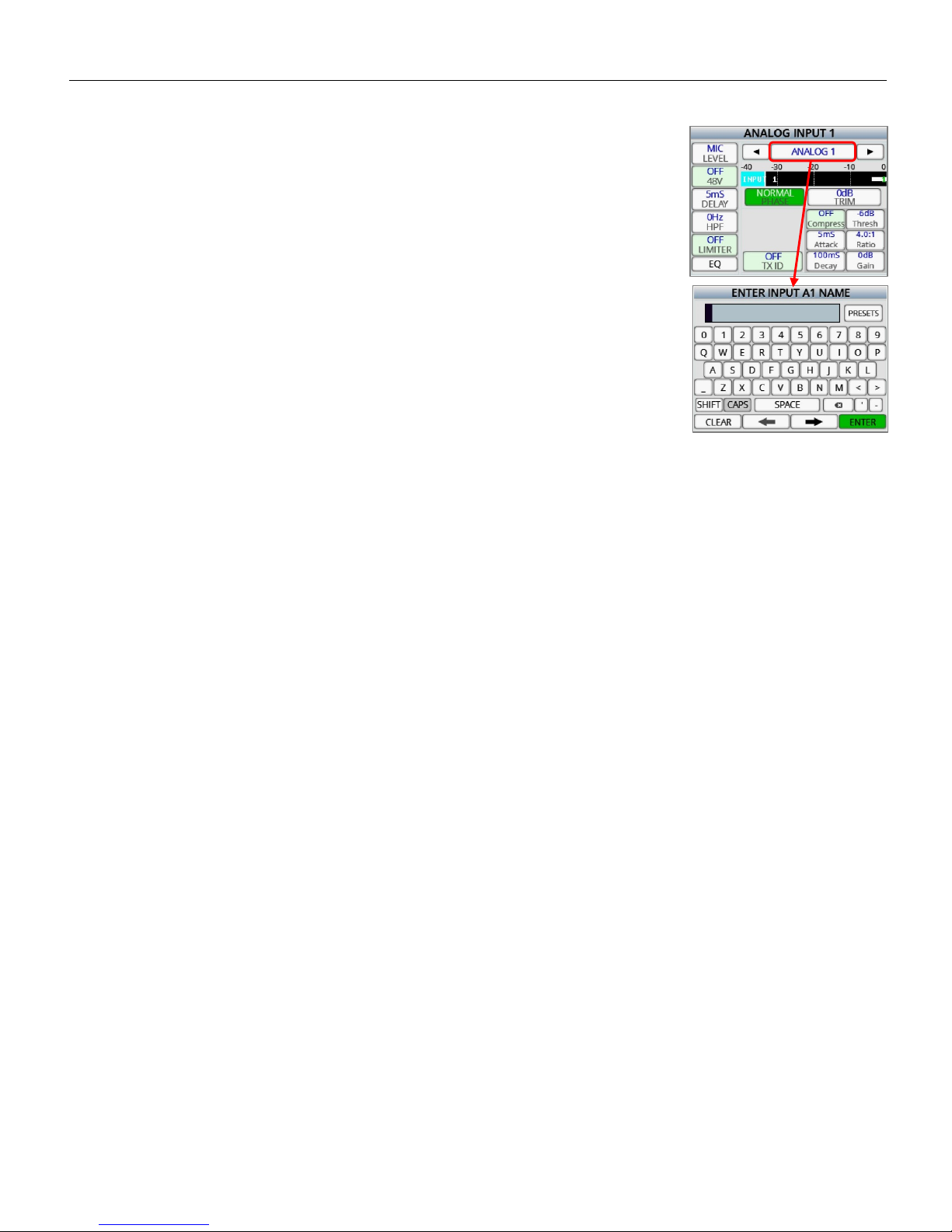
Naming an input ............................................................................................................................................................. 31
Adjusting the input paramaters ................................................................................................................................... 31
Adjusting the equalization ............................................................................................................................................ 32
Adjusting the phase of an input ................................................................................................................................... 32
Adjusting the input trim ................................................................................................................................................ 32
Adjusting the compressor settings .............................................................................................................................. 32
Adjusting the slate and com settings .......................................................................................................................... 33
ADJUSTING WIRELESS TRANSMITTERS VIA ZAXNET .....................................................................................................................34
Setting the ZaxNet unit code ........................................................................................................................................ 34
Adjusting transmitter gain ............................................................................................................................................ 34
Adjusting the transmitter frequency ........................................................................................................................... 34
3
Page 4

MY DEVA
......................................................................................................................................................................... 35
PRIMARY DRIVE - INTERNAL SATA ...........................................................................................................................................35
Formatting the SATA drive ............................................................................................................................................ 35
Selecting a record folder ............................................................................................................................................... 35
Naming a folder .............................................................................................................................................................. 36
Viewing, navagating and playing back the contents of a folder ............................................................................. 36
Editing the metadata for a segment ............................................................................................................................ 36
Erasing the current folder ............................................................................................................................................. 36
Deleating the last segment ........................................................................................................................................... 37
MIRROR DRIVES - CF1 AND CF2 ...............................................................................................................................................38
Selecting a drive ............................................................................................................................................................. 38
Setting the file type ........................................................................................................................................................ 38
Setting the file resoultion ............................................................................................................................................. 38
Remember mirror mode ............................................................................................................................................... 38
Formatting the mirror drive ......................................................................................................................................... 39
Setting the file naming protocol .................................................................................................................................. 39
Selecting the folder to mirror ....................................................................................................................................... 40
Selecting the mirror start and end segments ............................................................................................................ 40
Record Enable ................................................................................................................................................................. 40
Setting the mirror mode ............................................................................................................................................... 40
WRITING A SOUND REPORT ......................................................................................................................................................40
SETTING UP THE SOUND REPORT ...............................................................................................................................................41
RECORDING TO AN EXTERNAL SATA (ESATA) DRIVE. ................................................................................................................41
CUE MODE ....................................................................................................................................................................... 42
TURNING ON TONE ........................................................................................................................................................ 43
HEADPHONE MIX ............................................................................................................................................................ 44
SELECTING A HEADPHONE PRESET POSITION ..............................................................................................................................44
SELECTING THE AUDIO TO BE MONITORED .................................................................................................................................44
INVERTING HEADPHONE PHASE .................................................................................................................................................44
‘ENABLING THE PRESET POSITION ..............................................................................................................................................44
RECORD TRACK ENABLE ................................................................................................................................................. 45
SELECTING THE MEDIA TO ENABLE.............................................................................................................................................45
ENABLING A TRACK ..................................................................................................................................................................45
DISABLING A TRACK ..................................................................................................................................................................45
CLEARING A TRACK ASSIGNMENT. .............................................................................................................................................45
ENABLING / DISABLING ALL TRACKS ..........................................................................................................................................45
ABOUT DEVA ................................................................................................................................................................... 46
PRESSING THE ZNET KEY - FUTURE FEATURE .............................................................................................................. 47
SETTING THE TRANSMITT FREQUENCY .......................................................................................................................................47
SETTING THE ZAXNET POWER LEVEL .........................................................................................................................................47
POWER ROLL ENABLE ...............................................................................................................................................................47
TRANSPORT CONTROL ENABLE ..................................................................................................................................................47
GROUP CODE ..........................................................................................................................................................................47
TRANSMITTER ..........................................................................................................................................................................47
4
Page 5

PRESSING THE WIRELESS KEY - FUTURE FEATURE
...................................................................................................... 48
RX12 INTERFACE .....................................................................................................................................................................48
ADJUSTING THE RECEIVER PARAMATERS ....................................................................................................................................49
Setting the operating mode .......................................................................................................................................... 49
Adjusting the receiver frequency................................................................................................................................. 49
PRESSING THE CUE KEY .................................................................................................................................................. 50
PRESSING THE TIME CODE KEY ..................................................................................................................................... 51
MANUALLY ENTERING TIME CODE AND USER BITS ......................................................................................................................51
SETTING THE TC OUT AND TC DISPLAY SOURCE .........................................................................................................................51
SETTING THE TC MODE ............................................................................................................................................................51
SETTING THE TC FRAME RATE ..................................................................................................................................................51
ENABLING INCREMENT USER BITS ..............................................................................................................................................51
JAMMING TIME CODE AND USER BITS ........................................................................................................................................52
DISPLAYING THE TIME CODE SLATE ............................................................................................................................................52
PRESSING THE INPUT KEY .............................................................................................................................................. 53
PRESSING THE SCENE / TAKE / NOTE KEY .................................................................................................................... 54
METADATA ...................................................................................................................................................................... 55
ENTERING METADATA ..............................................................................................................................................................55
Increasing the scene number ....................................................................................................................................... 55
Resetting the take .......................................................................................................................................................... 55
Storing a note preset ..................................................................................................................................................... 55
Clearing the note field ................................................................................................................................................... 55
Navagating the folder .................................................................................................................................................... 56
Viewing the preset note list .......................................................................................................................................... 56
SATA DRIVES / COMPACT FLASH CARDS ...................................................................................................................... 57
SYNCING DEVA 24 TO A DENECKE SLATE ..................................................................................................................... 58
DEVA 24 CONNECTOR ASSIGNMENTS .......................................................................................................................... 59
AUDIO INPUT / OUTPUT CONNECTORS (XLR-3) ........................................................................................................................59
AUDIO INPUT / OUTPUT CONNECTORS (TA-5) .........................................................................................................................59
MONO & TAPPE OUTPUT CONNECTORS (1/8” TRS OR 1/8”TS) ..............................................................................................59
SLATE MICROPHONE INPUT CONNECTOR (1/8” TRS) ...............................................................................................................59
HEADPHONE OUTPUT CONNECTORS (1/4” TRS OR 1/8” TRS) .................................................................................................59
POWER CONNECTORS (HIROSE-4 CONNECTOR) ........................................................................................................................59
COM 1 / GPI REMOTE ROLL (DB9) ..........................................................................................................................................59
AES IN 1 THRU 16 (DB25) ......................................................................................................................................................60
AES DIRECT OUT 1 THRU 12 (DB25) .......................................................................................................................................61
AES IN 17 THRU 24 / AES OUT BUSES 1 THRU 8 (DB25) ........................................................................................................62
UPDATING FIRMWARE ................................................................................................................................................... 63
HOW TO UPDATING DEVA 24 FIRMWARE ..................................................................................................................................63
PRODUCT SUPPORT ........................................................................................................................................................ 64
DEVA 24 SPECIFICATIONS .............................................................................................................................................. 65
5
Page 6
Deva24 Left Side Panel
1 3 6 2 7
15
14
13
12
11
5
4
10 9 8
19
18
17
16
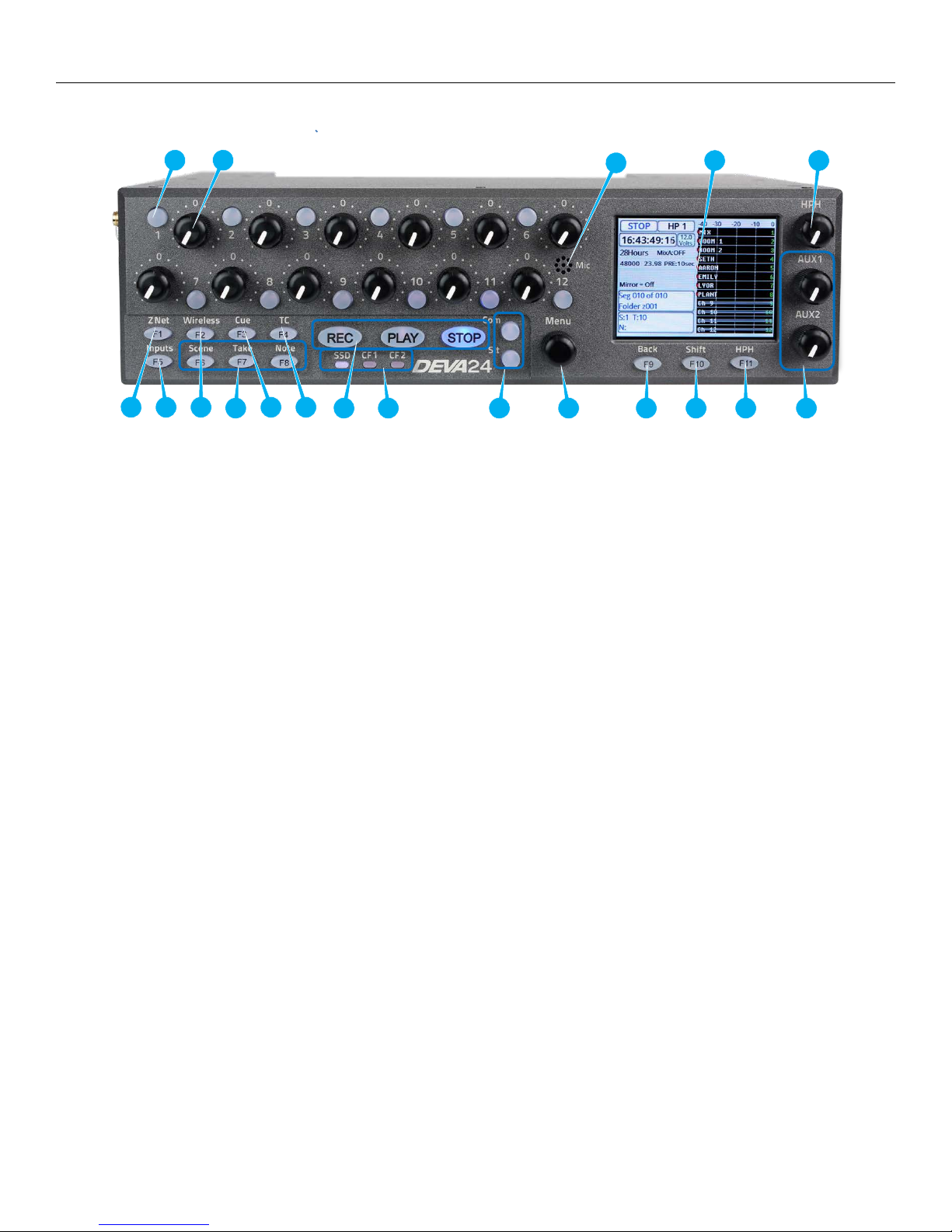
Front Panel
1. Pre fader listen keys PFL (12 total)
• Press to listen to the input that is routed to that fader.
• When in the fader assign menu pressing the key will jump to the fader assign matrix for that fader.
• When in the input configure menu pressing the key will jump to the assigned input and PFL that input.
2. Fader knobs (12 total)
Each of 12 faders can be assigned to act as a fader, input trim knob or a ZaxNet control knob.
3. Internal slate microphone
4. Color LCD Touch Screen - Daylight-readable color LCD touch screen.
5. Headphone knob - Rotate to adjust the headphone volume.
6. ZNET key - Press to open the ZaxNet transmitter menu.
7. Setup key - Press to open the input configure menu.
8. Wireless key - Press to open the RX-12 interface page.
9. Scene / Take / Note keys - Opens the Meta Data entry pages.
10. Cue key - Press to open the cue menu on the home screen.
11. Time Code key - Press to open the time code menu. A second press will display the time code slate.
12. REC / STOP / PLAY keys - Starts and stops recording and initiates playback. Pressing stop after stopping a
segment will open the false take screen.
13. PRI / CF1 / CF2 LED - Indicates that those drives are being written to.
14. SLT / Com keys - Press to activate the internal slate microphone (SLT) or external slate microphone (COM).
15. Menu encoder knob - Pressing the menu knob will open the main menu. When a parameter key is highlighted in
orange, turning the menu knob will adjust that parameter.
16. Back key
• Press to jump back one menu
• Press and tap a track on the home screen to name the track.
6
Page 7

Deva24 Left Side Panel
17. Shift key
• Press and tap a track on the home screen to record enable / un-enable the track.
• Press and tap the navigation arrows in the input configure menu to jump 4 inputs.
• Press and tap the input name key in the input configure menu to name the input.
• Press and tap the track name key in the mix track menu to name the mix track.
• Press and tap the output bus in the output routing menu to name the output bus.
• Press and tap the knob assign preset position to name the knob preset.
• Press and tap the aux knob preset to name the aux knob assign preset.
• Press and tap the headphone preset name key in the headphone assign menu to name the preset.
• Press and tap the folder in the primary folder menu to name the folder.
• Press and tap a segment from the folder menu to edit the metadata for the segment.
• Press and press the F5 key to update the software.
18. HPH key - Press to advance to the next headphone preset. Press and hold to jump back one headphone preset.
19. Aux 1 / Aux 2 knob - Rotate to adjust aux send levels.
7
Page 8
Deva24 Left Side Panel
1 2 3 6 4 5 11
12
13 7 14
15 8 9
10
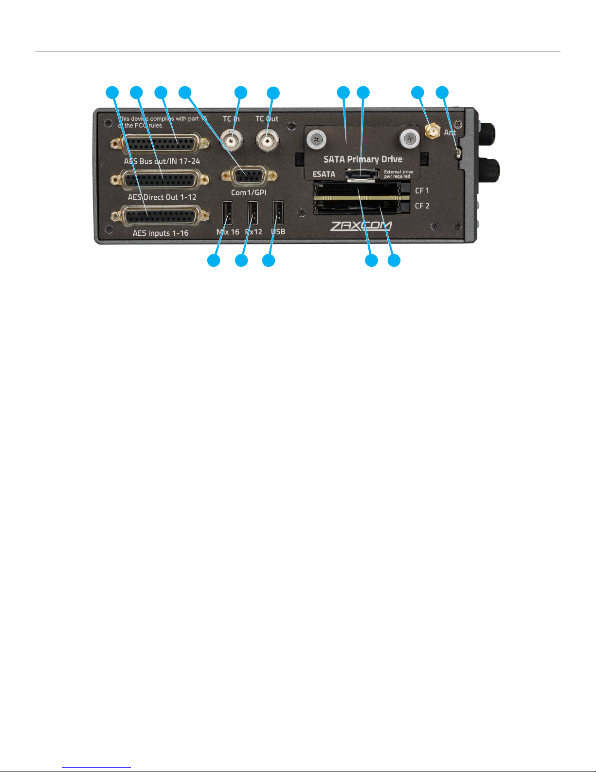
Left Side
1. AES Input 1 thru 16 (DB-25F)
These inputs will support an AES42 microphone. The input has a sample-rate conversion, allowing each input
to have a different sampling-rate. Deva will accept any unlocked AES signal with a sampling-rate of 32 to 192
kHz. The dynamic range of the sample-rate conversion is 124 dB, offering completely transparent conversion
of digital audio from one sample-rate to another.
2. AES Direct Outputs (DB-25F)
Direct AES outputs of the 12 analog inputs. These outputs are direct outputs with no effects or equalization
applied.
3. AES Bus outputs and AES input 17 thru 24 (DB-25F)
AES output busses 1 thru 8.
AES inputs 17 thru 24 - please note these inputs do not support AES42 microphones.
4. COM1 / GPI (DB-9F)
This connector is used for word clock out and supports a general purpose serial and parallel interface.
5. Time Code Output connector (BNC)
6. Time Code Input connector (BNC)
7. SATA- Primary Drive
The drive gets inserted behind the removable door. To remove the door turn the thumb screws
counterclockwise.
8. Connection for ESATA - mirror drive
9. ZaxNet antenna connector (SMA F)
10. Power switch
11. Mix16 connector
12. RX12 connector
13. USB connector - for connection to a PC or MAC
14. Compact flash 1 drive - mirror drive
15. Compact flash 2 drive - mirror drive
8
Page 9
Deva24 Right Side Panel
1
2
12 9 4 5 6 7 11 8 10 3 13
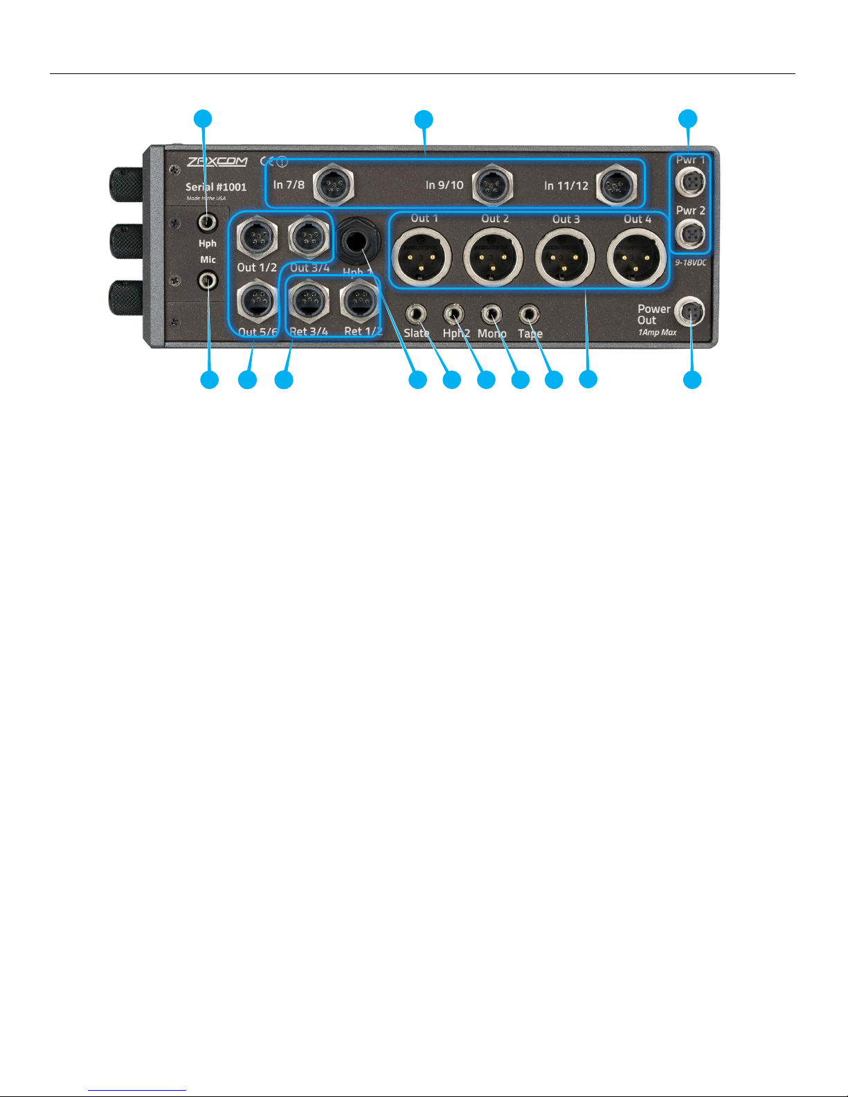
Right Side
1. Front panel headphone output (1/8” stereo jack)
This connector mirrors the 1/4” main headphone connector
2. Analog inputs 7 thru 12 (TA-5M)
These inputs are switchable between line level and mic level. These inputs have patented NeverClip preamps
with 136dB of dynamic range.
3. External Power Connector (Hirose-4F) X 2
These are redundant power inputs which will seamlessly switch to the supply with the higher voltage.
Deva 24 will operate on 10 to 18 VDC {1/2 A @ 12 VDC}
WARNING: Do NOT use a source higher than 18.0 VDC. Doing so can damage the unit’s power supply.
4. Front panel slate microphone input (1/8” (3.5mm) TRS)
5. Outputs 1 - 6 (TA-5M)
Outputs 6 channels of audio via output buses 1 thru 6
6. Returns 1 - 4 (TA-5M)
These inputs accepts a headphone level or line-level signal (Range: -20dBu and +30dBu)
• Line level analog inputs 13 thru 16
• These inputs can be used as returns. Each input is independent so audio can be monitored from four
different sources
7. Headphone #1 (1/4” stereo jack)
Main headphone out
8. External Slate Microphone input (1/8” (3.5mm) TRS jack)
This is where the external slate microphone is plugged into.
9. Headphone #2 (1/8” (3.5mm) TRS jack) Buses 7 / 8
10. Mono Output (1/8” (3.5mm) TRS jack) Bus 10
11. Tape Output (1/8” (3.5mm) TRS jack) Bus 9
12. Outputs 1 - 4 (XLR-3M)
Outputs 4 channels of audio via output buses 1 thru 4
13. DC Output (Hirose 4-F)
Supplies DC power to another device (1 amp max)
9
Page 10
Deva24 Rear
1
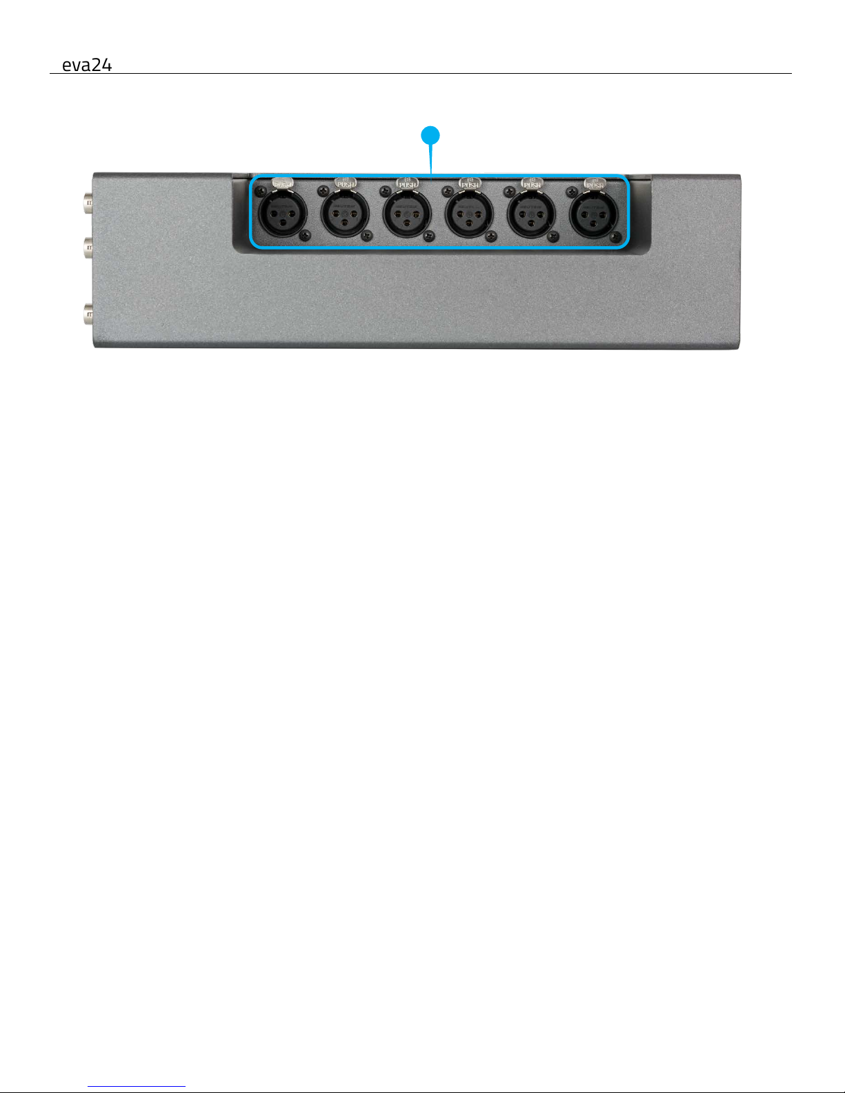
Rear
1. Analog inputs 1 thru 6 (XLR-3F)
These inputs are switchable between line level and mic level. These inputs have patented NeverClip preamps
with 136dB of dynamic range.
10
Page 11
MAIN MENU Meter Screens
11
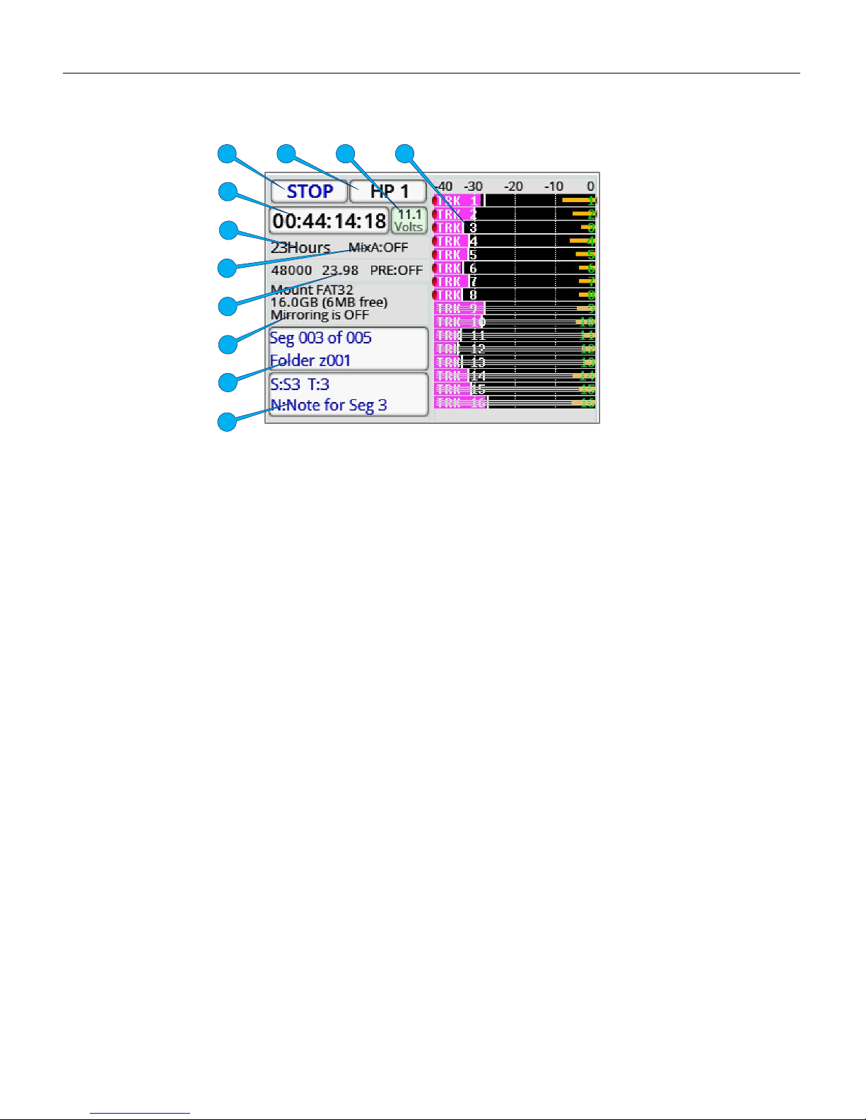
Home Screen
1. Transport status - Displays the status of the recorder. Tapping on the transport status key is a shortcut to the
main menu.
2. Headphone status - Displays what audio is being sent to the headphones. Tapping on the headphone status
key is a shortcut to the headphone routing matrix.
3. Voltage - Displays the incoming voltage of the power supply that is powering the Deva 24. If Deva 24 has a
power supply connected to both DC power inputs, the input with the higher voltage will be the one that is
powering the Deva 24 and that will be the voltage that is displayed.
4. Track Meters - Shows the record tracks levels in dBFS.
Please note that the number of track meters displayed can be adjusted in the mode menu - this example shows
16 tracks.
• If the track is named that track name will be displayed within the meter.
• If there is a horizontal line going through the track, that is showing that track is not record enabled. If a track
is record enabled there will be a red dot to the left of the meter.
As short cut hold the shift key and tap the track will record enable that track.
• If the compressor is engaged there will be a white line going from the right to the left showing the
compression.
• Tap on the track will isolate that track to the headphones.
5. Time Code - Displays the time code. This is user selectable to show the time code from either the time code
generator or the card. Tapping on the time code key is a shortcut to the time code menu.
6. Record time - Displays the time left on the primary media.
7. MixAhead - Displays time in milliseconds of the MixAhead feature.
8. Sample Rate / Frame Rate / Pre Record time - Displays sample rate, time code frame rate and pre-record
buffer time.
9. Record media information - Displays the remaining capacity on the primary and mirror media, the percentage
of the file that is being mirrored and what file number of the folder is being mirrored.
10. Segment - Displays the current segment being recorded and the folder it is being recorded to.
11. Scene / Take / Note - Displays the current scene, take and note metadata. Tapping on the key opens the
metadata management screen.
1
2
11
10
9 8 7 4 3 6 5
Page 12
Zaxcom Deva 24 Main Menu
12
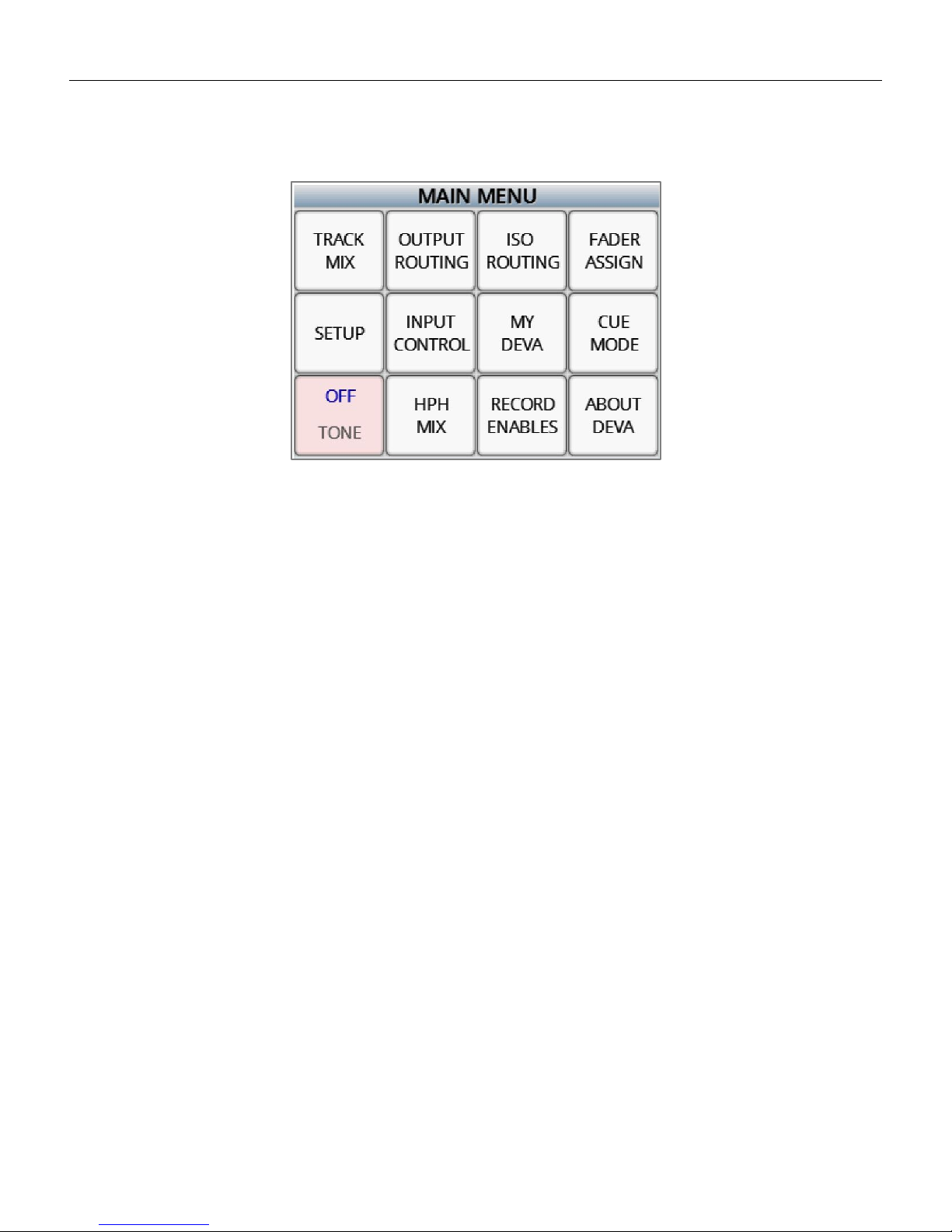
Main Menu
To access the main menu, press the MENU knob or tap the transport status key.
To return to the home screen, press the BACK button.
From the main menu the following menu items can be selected.
• Track Mix - This is where mix tracks (tracks 1 thru 8) are assigned inputs. Please note a mix track can also be an ISO
track if only one input is assigned to the track.
• Output Routing - This is where the 10 output busses get their assignments, and where the output levels are
adjusted.
• ISO Routing - This is where the ISO tracks (tracks 9 thru 24) are assigned an input.
• Fader Assign - This is where the 12 hardware knobs and 2 AUX knobs are assigned a function.
• Setup - This contains the sub menus where the Deva 24’s parameters are adjusted.
• Input Control - This is where the input parameters for the 16 analog and 24 digital inputs are adjusted.
• My Deva - This is where the record drives are enabled and the record parameters are adjusted.
• Cue Mode - This opens the cue menu on the home screen.
• Tone - Tapping the tone key toggles the internal tone oscillator on and off.
• HPH Mix - This is where the 10 headphone presets are set up from.
• Record Enables - This is where the record tracks are enabled and assigned to a record media(s).
• About Deva - This will display the information about the Deva.
Page 13
Zaxcom Deva 24 Track Mix
13
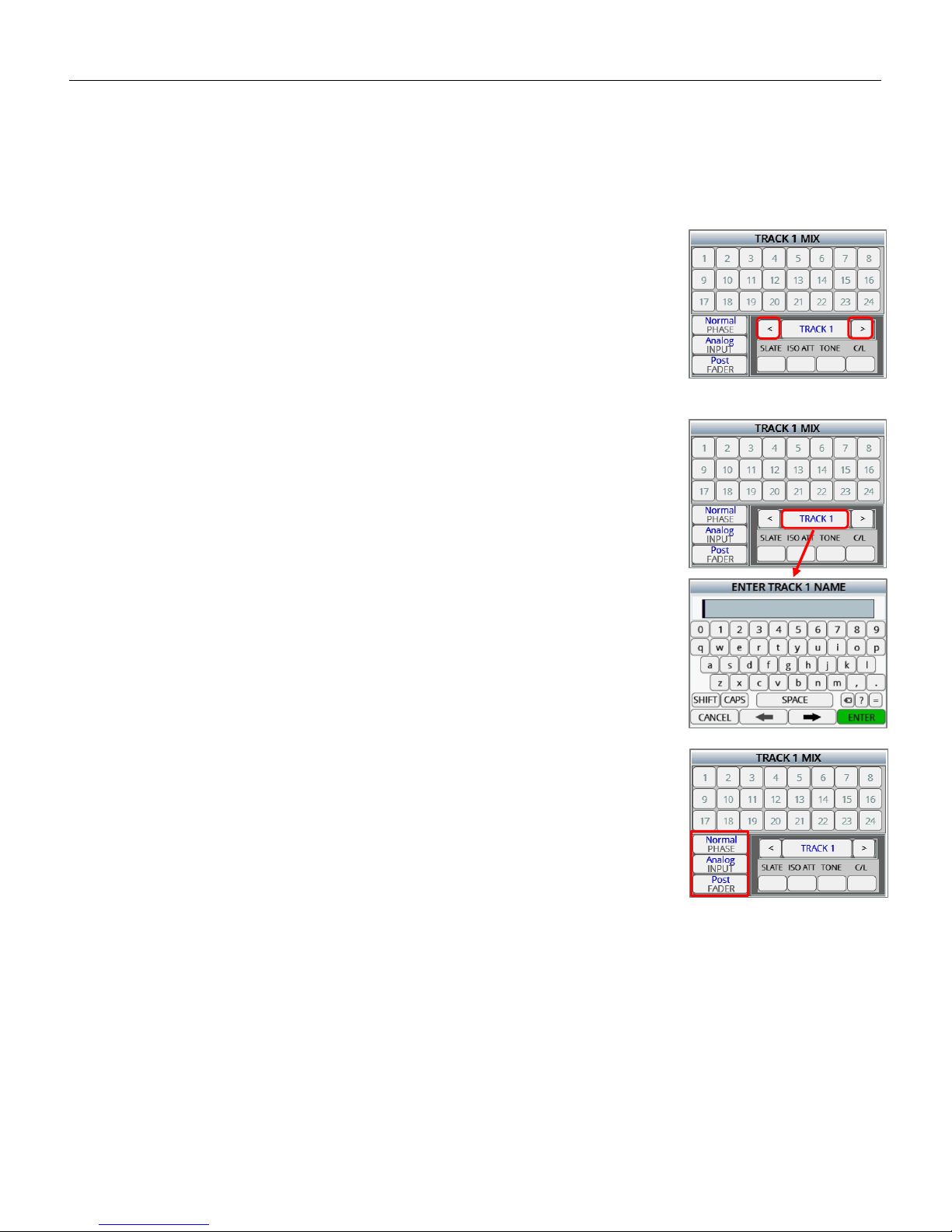
Track Mix
The track mix menu is where the mix tracks (tracks 1 thru 8) are assigned their inputs. Any combination of the 16
analog inputs or 24 digital inputs can be assigned to the any of the mix tracks from this menu. If a single input is
assigned to a track that track would become an ISO track.
Assigning inputs to a mix track
Selecting the track to assign
Select the track to be assigned by tapping on the arrow keys on either side of the
track name.
Naming a mix track
A mix track can be optionally named by holding the SHIFT key and tapping on the
track name key (between the arrows) which will open the on screen keyboard. After
a mix track is named, that name will be displayed in the meters and will be in the
metadata. A track name can contain up to 16 characters.
Setting the paramaters for the input(s) that will be assigned
From the lower left corner tap on the desired key to set the input parameter:
• Phase - normal or inverted
• Input type - analog or digital
• Routing - pre or post fader
After the parameters have been set, any input selected will follow the chosen
parameters. So for the example to the right when tapping on an input number
(1 thru 24) that input will be assigned to the mix track as analog input, routed post
fader with normal phase. Any combination of input parameters can be assigned to
a record track.
Page 14
Zaxcom Deva 24 Track Mix
14
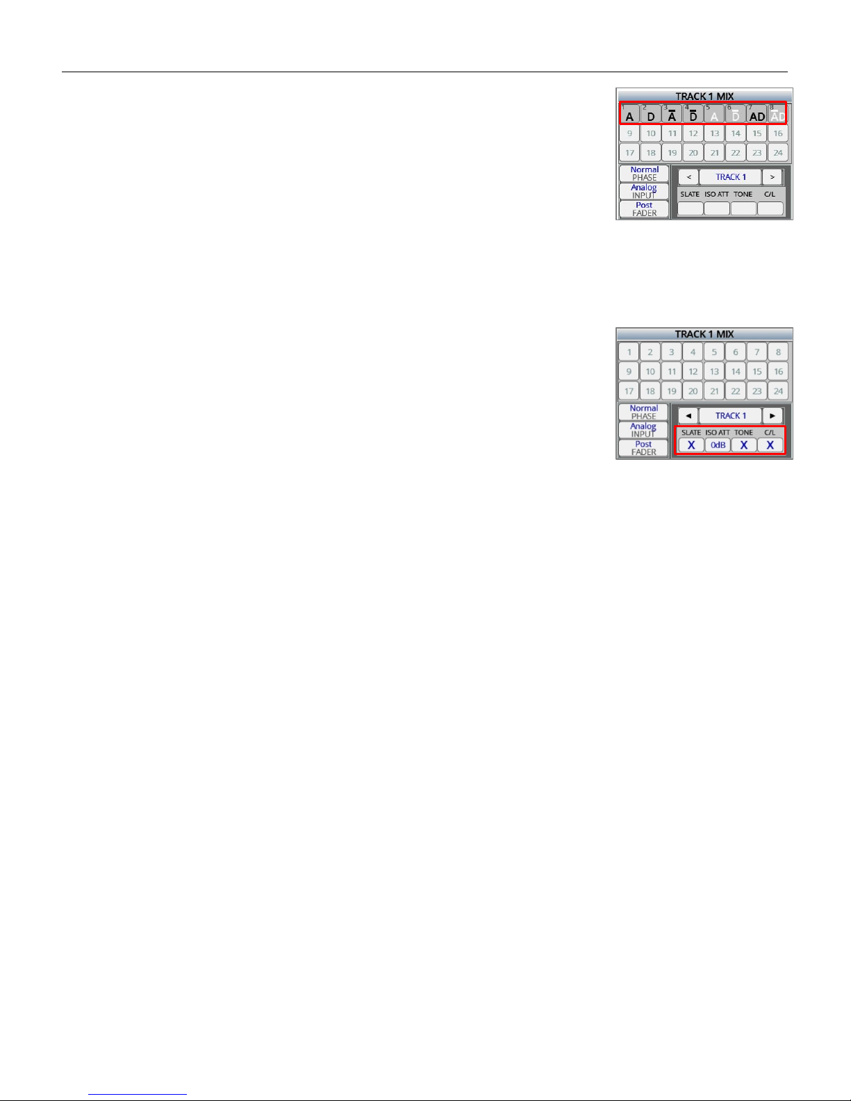
Assiging the inputs to the track
Tap on the desired input(s) (1 thru 24) to route those input to the selected mix
track. The number in the box represents the input number, for both analog and
digital. After the box is tapped the chosen parameter for that input will be
displayed as:
• An analog assignment will be displayed as an “A”
• A digital assignment will be displayed as a “D”
• If the phase is inverted a line will appear on top of the letter
• If the input is routed post fade the letter will be black
• If the input is routed pre fader the letter will be white
To remove an assignment select the same parameters (phase, input and fader),
then tap on the input to be removed.
Setting the paramaters for the track
Tap on the desired key to:
• Enable the slate microphone for that track
• Set the desired ISO attenuation (0dB, -6dB, -12dB, -18dB, -24dB) for that track
• Enable tone to that track - when tone is engaged
• Enable the compressor / limiter to that track
Page 15
Zaxcom Deva 24 Output Routing
15
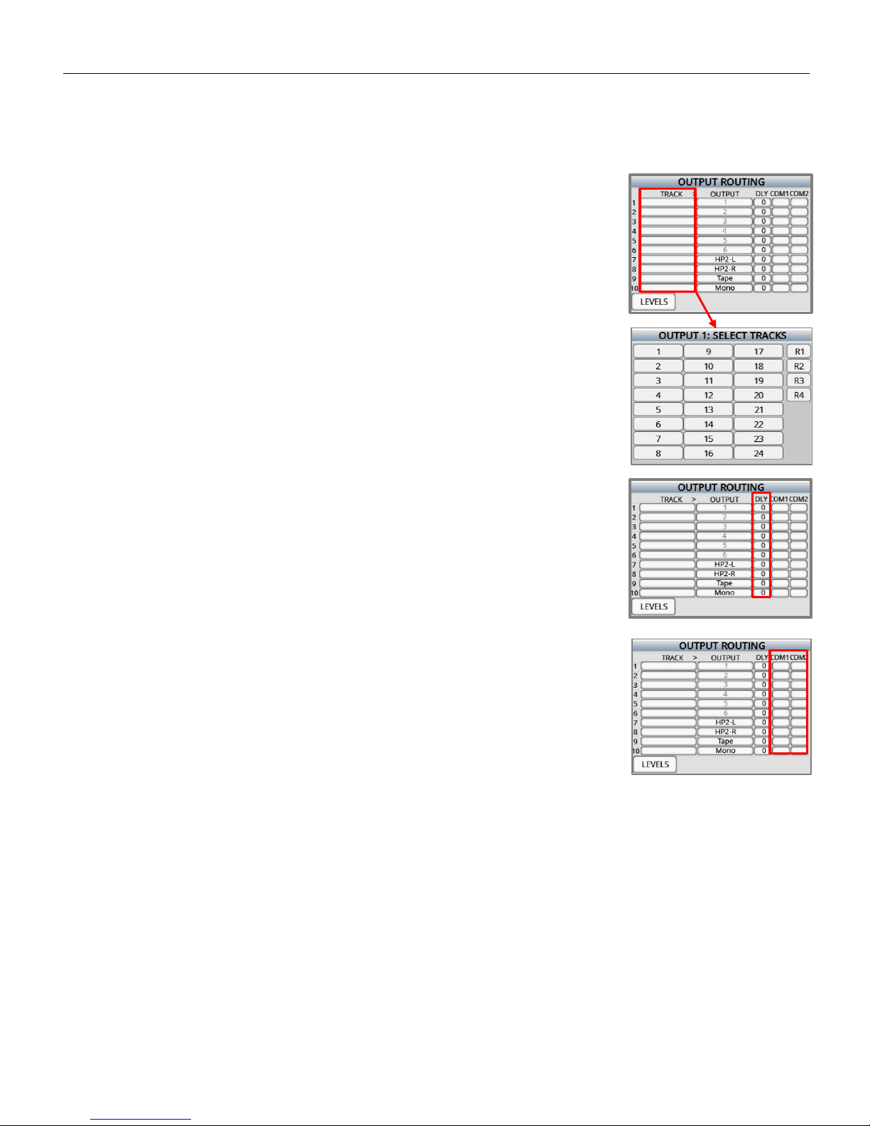
Output Routing
The output routing menu is where the record tracks are assigned to an output bus / busses.
Routing record tracks to an output bus
Selecting the output bus to be routed
Tap on the track box for the desired bus (1 thru 10) which will open the track
select matrix. The bus numbers are listed on the left.
• Output buses 1 thru 6 are routed to their corresponding XLR and TA5 output
number.
• Output bussed 7 and 8 are routed directly to the headphone 2 output.
• Output busses 9 and 10 are routed the tape and mono output.
Selecting the track(s)
When the track select matrix is open, tap on the track(s) and or return input(s) to be
routed to the output bus. After the track(s) have been selected the track number(s)
will be displayed in the track box.
Adding delay to the outputs
Delay can be optionally added to each output bus. To add delay, tap on the delay
box for the desired bus. Tap on the box once and it will turn it orange; when the
box is orange the menu encoder knob can be used to adjust the delay. Tap on the
box one more time to open the delay entry menu. From the menu the delay can
be manually entered. Delay can be set up to 999mS.
Assiging coms to an output bus
Tap on the desired com box to route the coms (1 and 2) to output bus. An “X” will
appear when a com has been routed to the bus. Please note access to com 2 is
available when using the Mix 16.
Page 16
Zaxcom Deva 24 Output Routing
16
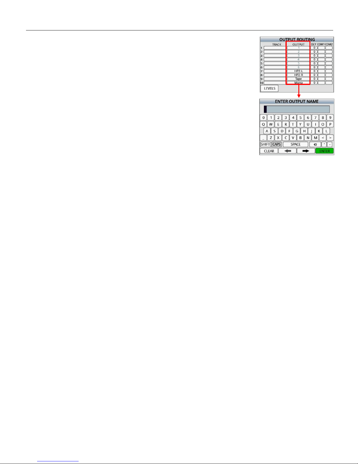
Naming the output bus
Each output bus can be optionally named for easy identification. To name the output
bus, hold the SHIFT key tap on the output bus number to open the text entry
keyboard. Then from the keyboard enter the desired name.
Page 17
Zaxcom Deva 24 Output Routing
17
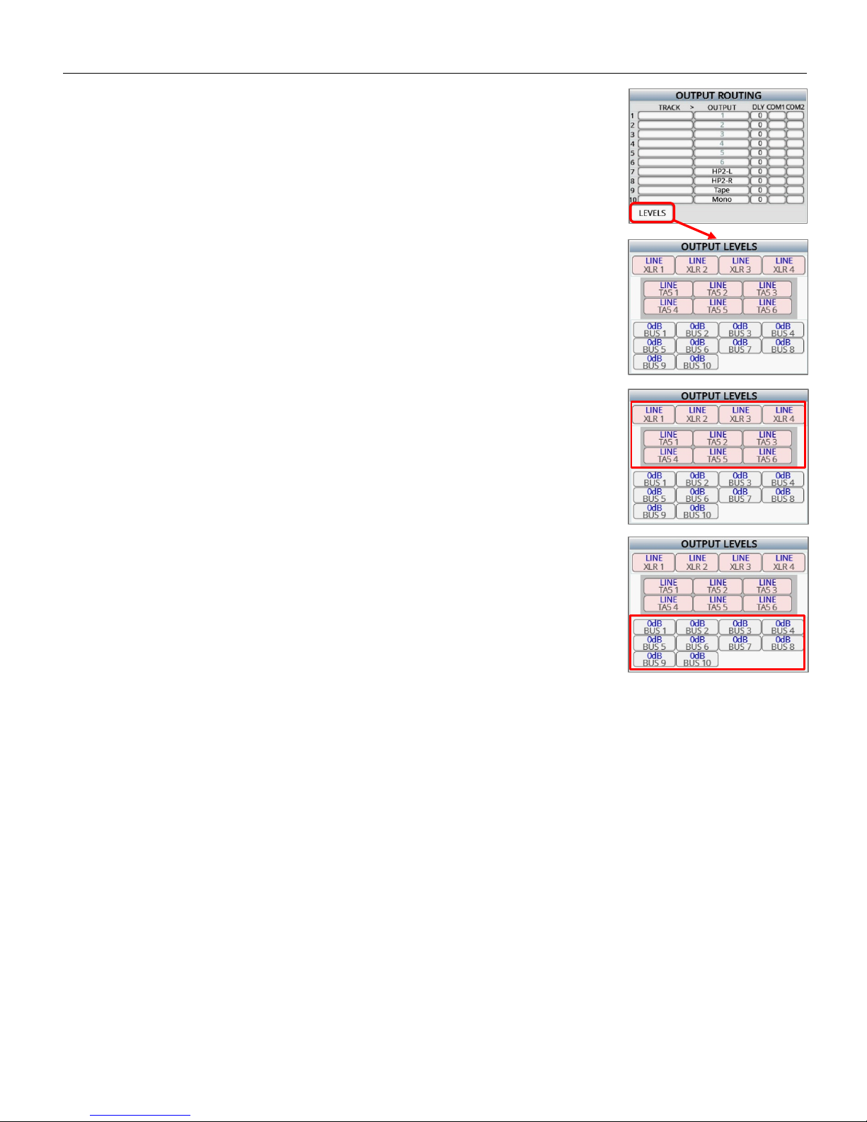
Adjusting output levels
Tap on the LEVELS key on the lower right corner to open the output level menu.
From the output level adjust menu the individual output levels for the XLR and
TA5 connectors can be adjusted. Tapping on the output key will cycle through
Line, Mic and -10dB.
Attenuating an output bus
From the output levels menu tapping the BUS keys will allow for the individual
bus output to be attenuated up to 24dB.
Page 18
Zaxcom Deva 24 ISO Routing
18
ISO Routing
The ISO routing menu is where the ISO tracks (tracks 9 thru 24) are assigned an input. Any of the 16 analog inputs or
24 digital inputs can be assigned to the any one of the ISO tracks.
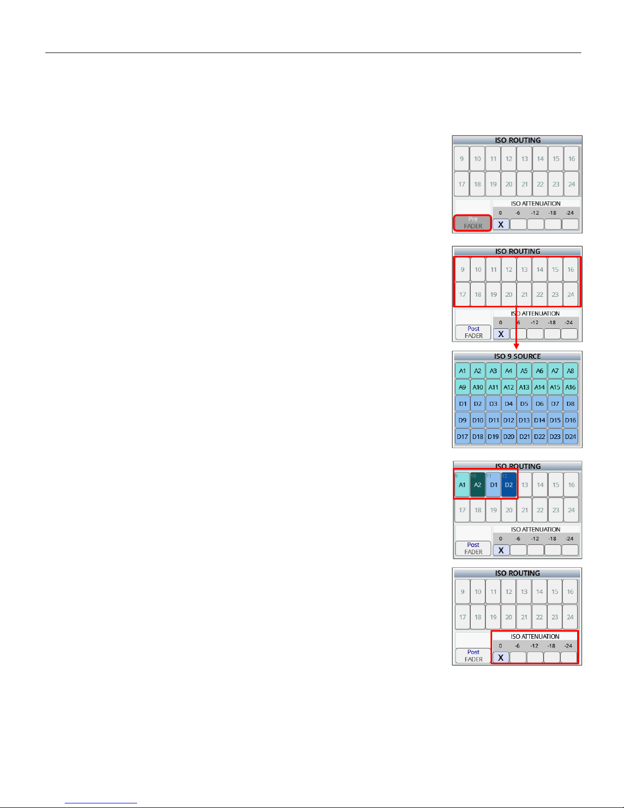
Assigning an input to a ISO track
Setting the ISO track as pre or post fader
Each ISO track can be routed as either pre or post fader. Tapping on the FADER key
on the lower left will toggle between “Pre” and “Post” fade. This sets the state of
how the input will be routed. So for example if the “Pre” is displayed any input
selected will be routed pre fader. If the “Post” is displayed any input selected will be
routed post fader.
Routing an input to the ISO track
Select the desired ISO track (9 thru 24) to be assigned by tapping on the track
number. This will open the ISO source menu for that track. From the ISO source
menu tap on the desired input to be routed to that track.
To remove an ISO routing select the track number which will open the ISO source
menu, then tap on the input to toggle it off.
An analog input routed post fader will be displayed light green and an analog input
routed pre fader will be displayed dark green.
A digital input routed post fader will be displayed light blue and a digital input routed
pre fader will be displayed dark blue.
Enabling ISO attenuation
The NeverClip™ inputs allow large signals to travel through the digital mixing
engine using 32 bit floating point numbers. Once these large signals are
recorded into a 24-bit WAV (or MARF) file, the advantage of floating point
math is lost and these signals can clip if not using a card limiter.
ISO Attenuation allows the ISO record tracks to be attenuated by a user selectable
amount of 6, 12, 18 or 24dB. This allows audio to be recorded without clipping
even if its dynamic range would normally be too large. This gain reduction amount
is stored in the metadata of the WAV file so post production can easily restore the
amplitude of the ISO tracks when necessary. To enable ISO attenuation tap on the
desired attenuation amount from the ISO attenuation matrix. Please note that the
ISO attenuation is a global setting - meaning the same amount of attenuation will
be applied to all tracks.
Page 19
Zaxcom Deva 24 ISO Routing
19
Naming an ISO track
An ISO track will be named when it is assigned a named input.
To name an input go to the input control menu and hold the SHIFT key and tap on
the INPUT NAME key to open the on screen keyboard. Each input name can be up to
16 characters in length. Then when that input is assigned to an ISO track the
inputted name will become the track name, and will be stored in the metadata.
Page 20
Zaxcom Deva 24 Fader Assign
20
Fader Assign
The fader assign menu is where the 12 hardware faders are assigned their function. Each individual fader can be
assigned to control input trim, it can be assigned to be a fader for any input or, it can be assigned to remote control
the transmitter input gain, via ZaxNet, for any unit code.
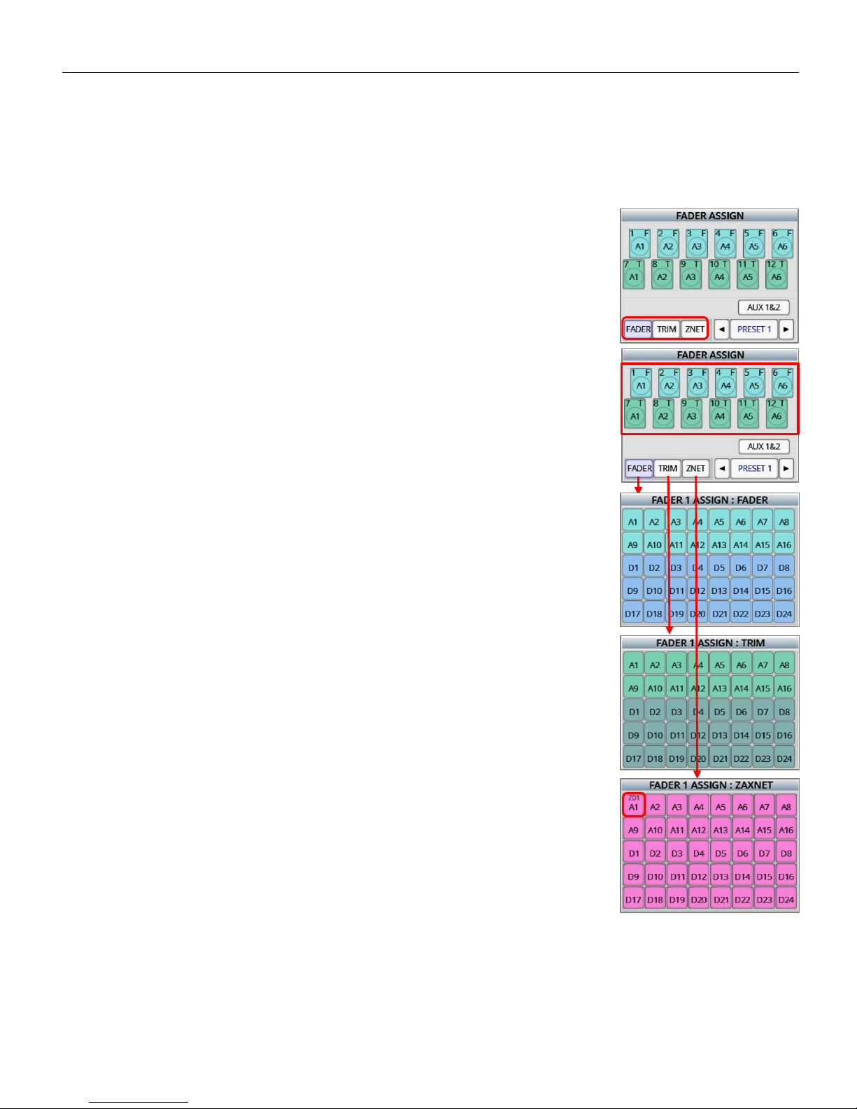
Assigning a function to a fader
Setting the function of the fader
Tap the assign key on the lower left of the screen.
• Fader - The knob will be a fader for the selected input.
• Trim - The knob will control the input trim for the selected input.
• ZNet - The knob will control the input gain of a Zaxcom transmitter.
Assigning an input to the fader
After setting the function with the assign key tap the desired fader (1 thru 12). Then,
depending status of the assign key, the fader, trim or ZaxNet assign matrix will open.
Then from that matrix tap on the desired input to be assigned to the fader. If desired
multiple inputs or multiple trims can be assigned to a single fader.
To remove or change an assignment, select the same assignment or choose a
different input.
Please note that when assigning a fader to control transmitter gain via ZaxNet the
unit code will need to be assigned for that input from the INPUT CONTROL menu.
To do so from the INPUT CONTROL menu tap on the TX ID key and assign a unit code
for that input. Then when assigning a knob for that input to ZaxNet the unit code will
be displayed on the input key.
Page 21
Zaxcom Deva 24 Fader Assign
21
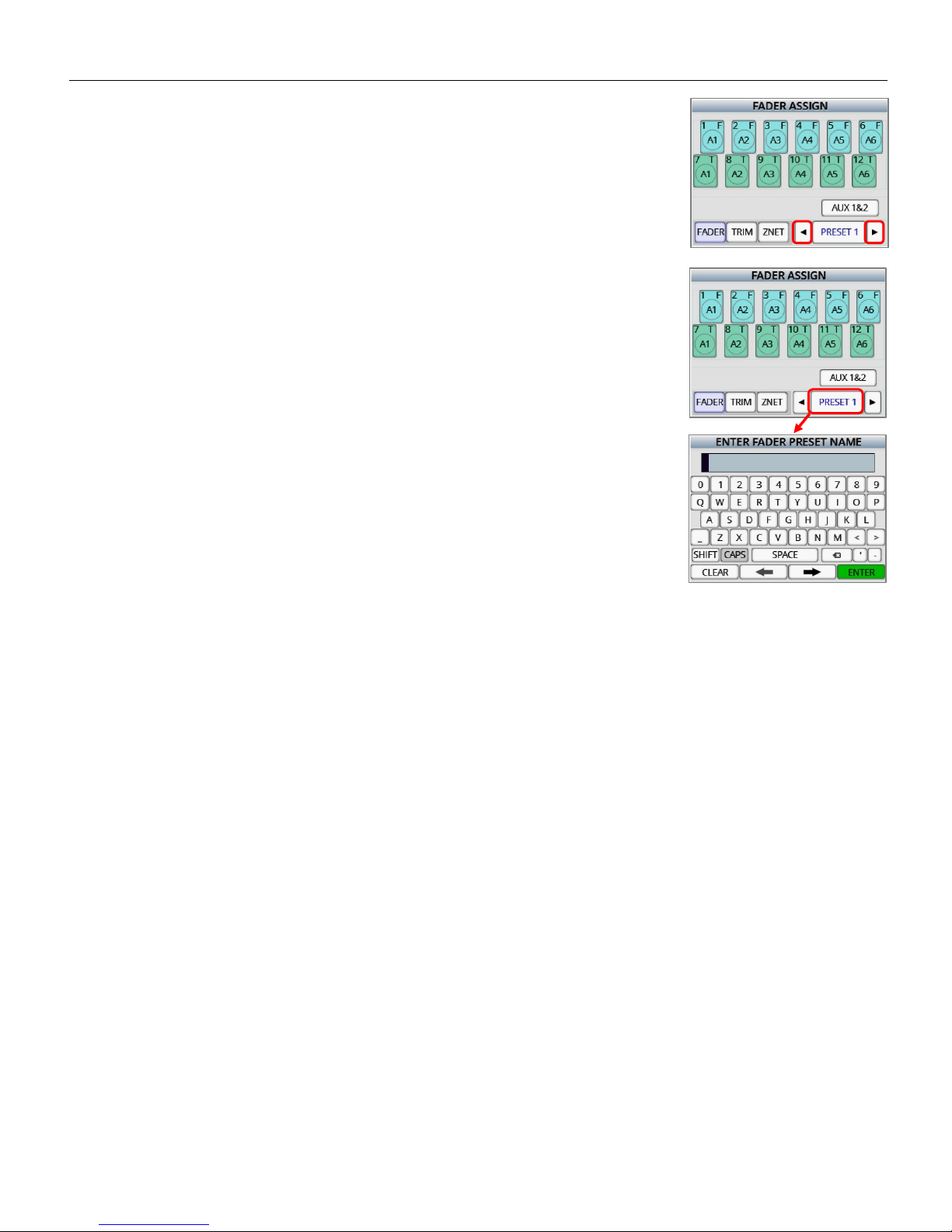
Selecting a fader preset position
Deva 24 has 5 user assignable fader preset positions. To select a preset position tap
the arrows on either side of the preset number.
Naming a fader preset position
Each fader preset position can be named for easy identification. Each fader preset
can contain up to 8 characters. To name the fader preset position, hold the SHIFT
key and tap on the preset number key to open the text entry keyboard. Then from
the keyboard the desired name can be entered.
Page 22

Zaxcom Deva 24 Fader Assign
22
Assigning an output bus(s)to Aux knob 1 & 2
Tap the AUX 1&2 key to open the aux assign menu.
From the Aux assign menu, output busses can be assigned to the two aux knobs. If
desired multiple busses can be assigned to each aux knob.
After assigned the aux knobs will attenuate the output(s) assigned to them.
Selecting an Aux knob preset position
There are 5 auxiliary assign presets to select a preset tap on the arrow keys on either
side of the preset number.
Naming the Aux knob preset position
Each auxiliary preset position can be named for easy identification. Each preset can
contain up to 8 characters. To name the aux knob preset hold the SHIFT key and tap
on the preset number key to open the text entry keyboard. Then from the keyboard
the desired name can be entered.
Page 23

Zaxcom Deva 24 Setup Menu
23
Setup Menu
The parameters of Deva 24 are adjusted from the setup menu.
Sample Rate
Tapping on the SAMPLE RATE key will cycle through the sample rates. Deva 24 can record sample rates of 48000,
48048
Mix Ahead - future feature
Mix Ahead allows for a user selectable amount of time, up to 250ms, can be inserted between when the audio heard
in the headphones and the fader motion recorded to the MixAhead track. For example if 100ms of MixAhead is set,
this will allow an extra 100ms in order to make fader adjustments. This 100ms eliminates the problem of fader
latency and human reaction time, which can potentially ruin the mix track. So basically MixAhead adds time to the
fader moves which can make the mix cleaner and more accurate.
A MixAhead track will be an additional track that can be utilized by post or not, as the traditional mix track is always
recorded as well. Deva 24 will time align all Mix, ISO and MixAhead tracks so that post production can seamlessly
cross fader between any combination of tracks.
Tapping on the MIXAHEAD key will turn the key orange, then using the menu encoder knob the MixAhead time can
be dialed in. Tapping the key again to open a numeric key board where the MixAhead time in milliseconds can be
entered.
Pre-Record time set
From the point the Deva24 is powered up, all inputted audio is being processed. When pre-record is enabled, up to
10 seconds of that processed audio is held in a pre-record buffer. Then when the record key is pressed that stored
audio, with its time code, is included the current take.
Tapping the PRE-RECORD key will turn the key orange, then using the menu encoder knob the pre-record time can be
dialed in. Tap on the key again will open a numeric key board that will allow the pre-record rate to be entered. The
pre-record buffer can be set from 1 to 10 seconds in 1 second increments.
Please note the prerecord buffer is dumped after any of the following settings are changed: sample-rate, time code,
user-bits, frame-rate or record enable. After these parameters are changed the buffer will start to re-build.
Tone Level
Tapping the TONE LEVEL key will adjust the level of the reference tone that is recorded on the record tracks and sent
to the output busses. The tone level can be set to -12, -14, -16, -18 or -20dB.
Please note it is recommended, for most applications, to keep the tone level set at -20dB.
Page 24

Zaxcom Deva 24 Setup Menu
24
Modes Menu
Tap on the MODES MENU key to open the mode sub-menu.
Transport Control - The transport control adjusts the way Deva 24 will go into
record.
• Normal - Deva 24 will go into record when the record button is pushed.
• Auto Load - Deva 24 will go into to record when it senses record run time code
coming from an external source
.
Remote Roll Enable
• Off - Remote roll will be shut off
• Rising - Remote roll will engage when there is a low to high voltage transition
• Falling -Remote roll will engage when there is a high to low voltage transition.
Serial Remote
FUTURE FEATURE
ISO Effects
• Off - Equalization and compressor settings will affect the mix tracks only and will not affect the ISO tracks.
Meaning the ISO tracks will be recorded clean.
• On - Equalization and compressor settings will affect to both the mix track and the ISO tracks.
Slate microphone select
• Internal - The internal slate microphone on the front panel will be used when the SLT key is pushed.
• External - The slate microphone that is connected to either of the two external slate microphone input jacks on
the side of the Deva 24 will be used when the SLT key is pressed.
TC Slate orientation
• Normal - The time code slate will appear right side up.
• Flipped - The time code slate will appear inverted. This is for when the Deva 24 is being worn in a sound bag
and a camera needs to shoot the slate for reference. This way the slate will appear in the correct perspective to
the camera.
Input mode
• 24D - 12A - Deva 24 can receive 24 digital inputs and 12 analog inputs.
• 16D - 16A - Deva 24 can receive 16 digital inputs and 16 analog inputs.
Dante routing
Only available for Dante enabled units
• Normal - Those AES inputs will be active.
• Dante - Those AES inputs will be disabled which allow Deva 24 to receive data channels Dante (up to 16
channels of audio via Dante).
Page 25

Zaxcom Deva 24 Setup Menu
25
Meter adjust
Tapping the METERS key will open the meter menu.
To view the input source meters tap the source key on the upper left. This will change
which meters are displayed on this screen, please note this will not change the meters
displayed on the home screen.
Tapping on the METERS key will cycle through the number of record track meters that
will be displayed on the home screen. The choices are 8, 12, 16, 20 or 24 meters.
Tapping on the AUTO ISO key to remove mix tracks (tracks 1 thru 8) with nothing
assigned to them from the home screen
• Off - All mix track meters will be displayed on the home screen.
• On - Only mix tracks with something assigned to them will be displayed on the
home screen.
Page 26

Zaxcom Deva 24 Setup Menu
26
Post Record time set
Post-record is how long Deva 24 will continue to record after stop is pushed.
Tapping the POST-RECORD key will turn the key orange, then using the menu encoder knob the post-record time can
be dialed in. Tap on the key again will open a numeric key board that will allow the post-record rate to be entered.
The post-record can be set from 1 to 10 seconds in 1 second increments.
Effects Copy
Effects copy will allow the compressor, notch, equalization and delay settings to be
copied from one input to other inputs.
To copy the effects:
• Turn on the desired effects to be copied by tapping the desired effects key(s).
• Select the input to be copied FROM by tapping the FROM key.
• Select the input(s) that the effects will be copied to by tapping the TO key.
• Tap the COPY key.
Clock and date set
Tapping on the CLOCK key will open the date and clock menu. This is where Deva 24’s
internal clock and calendar will be adjusted from.
The date style can be set to either US (MMDDYY) or European style (DDMMYY).
Maintaining the internal clock
Please note that Deva 24 contains a battery backed real-time clock. This clock is
used to maintain running time code and internal calendar. It is advised to change
the battery every 2 to 3 years.
The battery is a CR2320 3V coin cell battery.
Page 27

Zaxcom Deva 24 Setup Menu
27
Memory Menu
Tapping on the MEMORY key will open the memory menu. Deva 24 has 8 user assignable memory presets where all
user set parameters are saved and can be recalled as needed. Please note that after doing a factory restore, all stored
memories will be erased.
Saving a Deva 24 setup to a memory position
From the lower right corner tap on the MODE key to cycle through the memory
functions.
• Store - Tap to STORE MEM position number to save the current Deva 24 setup
to a memory position.
• Recall - Tap on the RECALL MEM position number to recall a stored setup.
• Name - Allows a memory set up to be named. Each memory name can
contain up to 6 characters. To name the position tap on the NAME MEM key
to open the text entry keyboard.
Page 28

Zaxcom Deva 24 Setup Menu
28
Saving a Deva 24 setup to a compact flash card
The Deva 24 setup can be saved to either compact flash card, so the settings can
easily be transferred to another Deva 24, or saved so a set up can be recalled
after a factory default reset is done.
• To save the settings to a CF card, set the mode key on the lower right to
STORE then tap on the desired CF position.
• To recall the setting from a CF card set the MODE key on the lower right to
“RECALL” the tap on the desired CF position.
Recalling factory defaults
From the memory menu the Deva 24 factory defaults can be recalled by tapping
on the RECALL FACTORY DEFAULTS key.
Warning all user set parameters will be cleared when a factory recall is done.
Clearing fader assignments
From the memory menu the Deva 24’s faders assign can be cleared by tapping on
the CLEAR FADER key.
Page 29

Zaxcom Deva 24 Setup Menu
29
Mixer Faders
The MIXER FADERS key assigns input(s) and sets functions to the faders of a Mix 16 control panel.
Slecting a fader bank to assign
Tap on the arrow keys on either side of the BANK key to select one of the 5 Mix16
fader banks.
Slecting fader groups
Tap on the EXT FADER key on the top left to toggle between fader groups 1 thru 8
and fader groups 9 thru 16.
Assigining a trim pot function to a fader strip
Tap on the box above the fader to assign a function to that trim pot.
• Z - The fader will control the input gain from a Zaxcom wireless transmitter for
the selected input.
• T - The fader will control the input trim for the selected input.
Assigining an input(s) to the fader
Tap on the fader to open the fader assign matrix. From the matrix any analog or
digital input(s) can be assigned to a Mix16 fader. Multiple inputs can be assigned to
any fader.
Page 30

Zaxcom Deva 24 Setup Menu
30
User Interface
From the user interface menu the LCD brightness and membrane keys brightness can
be adjusted. To adjust the brightness tap on the the desired key once, which will turn
the key organge, then the menu encoder can be used to adjust the brightness. If the
key is tapped a second time the on screen keyboard will open and the brightness
level can manually be entered. The brightness can be adjusted from 1 to 10 with 10
being the brightest.
Page 31

Zaxcom Deva 24 Input Control
31
Input Control
The input control menu is where input parameters are adjusted for both the analog and digital inputs.
Configuring an input
Selecting an input to configure
To select the desired input tap on the arrow keys on either side of the input name.
That will jump to the next / previous input. Holding the SHIFT key while tapping the
arrows will change inputs by 4.
Naming an input
Each input can be optionally named for ease of identification. Also when a named
input is assigned to an ISO track the entered name will become the track name. That
name will be displayed in the track meter on the home screen and will be embedded
in the metadata for that track.
To name the input hold the shift key and tap on the INPUT NAME key to open the on
screen keyboard. Each input name can be up to 16 characters in length.
Adjusting the input paramaters
From the left side of the input configure screen the following parameters can be
adjusted:
• Mic / Line input - analog input 1 thru 12 only
• 48 volt phantom - analog inputs 1 thru 12 only
• AES 42 power - digital input 1 thru 16 only
• Input delay - adjustable from 0 to 40 milliseconds
• High pass filter - adjustable from 0 to 240Hz
• Limiter Off and On
• Equalization
Page 32

Zaxcom Deva 24 Input Control
32
Adjusting the equalization
Deva 24 has a three band equalizer for each input. To access the equalization adjust
menu tap on the EQ key.
From the equalization menu the low shelf, peaking, and high shelf can be adjusted by
tapping on the desired key.
After the parameter is selected the level, frequency and Q can be individually
adjusted for each parameter. To adjust the parameter tap the key once which will
turn the key orange and the parameter can be adjusted with the menu encoder knob.
Tap on the key again will open the numeric entry menu where the desired value can
be manually entered. As the equalization is adjusted it can be seen on the frequency
response graph.
Deva 24 also has a bypass feature where the set equalization can be bypassed while
still maintaining the configured settings, to bypass the equalization tap on the BYPASS
key on the top left.
If the PFL key is pushed the equalization menu will jump to the input associated with
that PFL button, and the audio from that input will be isolated to the headphones.
There are also two notch filters can be enabled and adjusted from this screen. Both
the frequency and Q can be adjusted for each notch filter.
Adjusting the phase of an input
Tapping on the PHASE key will invert the phase of the input. If the phase is set to
normal the key will be green, if the phase is inverted the key will turn red.
Adjusting the input trim
Tapping on the TRIM key will turn the key orange; this will allow the trim to be
adjusted using the menu encoder knob. Tap on the key again to open the numeric
entry menu when the trim can be manually entered. Please note if input trim is
assigned to a hardware fader the trim will not be able to be adjusted with this key.
Adjusting the compressor settings
From the right side of the input configure screen the compressor can be enabled
and the following parameters can be adjusted:
• Attack
• Decay
• Threshold
• Ratio
• Gain
Please note the compressor settings are global - meaning that the same compressor
settings will be applied to each input that has the compressor enabled.
Page 33

Zaxcom Deva 24 Input Control
33
Adjusting the slate and com settings
To access the internal slate, external slate and com inputs use the arrow keys on
either side of the input name. The slate and com settings are located after the digital
inputs.
From each menu the input trim can be adjusted and the phase can be inverted.
Page 34

Zaxcom Deva 24 Input Control
34
Adjusting wireless transmitters via ZaxNet
If an input is receiving audio from a Zaxcom wireless transmitter the input gain and UHF transmission frequency can
be remotely adjusted from the input control screen.
Setting the ZaxNet unit code
Each individual transmitter needs to have a unique identification number so the
remote control commands can be sent to the proper transmitter. To set the
transmitter identification code, tap the TX ID key and set the desired number. After
the TX ID is set, the keys for remote TX GAIN and TX FREQ adjustment will appear.
Then, if desired, a fader can be assigned to control the input gain for that
transmitter. To do so simply select ZNET in the fader assign menu, then choose that
input in the ZaxNet assign matrix. Then the selected knob will remotely adjust the
input gain on the transmitter.
Adjusting transmitter gain
Tap on the TX GAIN key to turn the key orange, when the key is orange the menu encoder knob can be used to
remotely adjust the input gain of transmitter with the corresponding transmitter ID.
Adjusting the transmitter frequency
Tap on the TX FREQ key to turn the key orange when the key is orange the menu encoder knob can be used to
remotely adjust the UHF frequency of the transmitter with the corresponding transmitter ID. If the key is tapped
again the transmitter frequency menu will appear and the desired frequency can be manually entered.
Page 35

Zaxcom Deva 24 My Deva
35
My Deva
The My Deva menu is where the record parameters for the primary drive and mirror drives are adjusted from.
Primary Drive - Internal SATA
The SATA drive is the primary record drive, its audio is recorded as a MARF II file.
MARF II (mobile audio recording format) is a lossless fault tolerant recording system.
MARF II is a very robust recording system where the recorded digital files do not need
to close or finalize. So if power is lost during recording, all audio right up to the point
when power is lost, will be preserved. MARF II’s robustness also lends itself to be
often immune from viruses and corruption that can affect standard recording formats.
MARF II files can be quickly and easily converted to BWF files and MP3 files by using
ZaxConvert. When using ZaxConvert all timecode and Meta Data is preserved.
ZaxConvert is available for free and can be downloaded from the Zaxcom website.
Formatting the SATA drive
From the My Deva page tap on the INTERNAL SATA key to open the internal disk
utilities menu. Then tap on the FORMAT DRIVE key.
A confirmation screen will appear before the drive can be formatted.
Warning when formatting the drive all previously recorded audio will be erased.
Selecting a record folder
All files are recorded into individual folders. To select a folder tap on the CURRENT
FOLDER key, this will open the folder list.
The folder list will display the folder name, how many segments are recorded in the
folder and, the total size of the files in each folder.
To choose a folder use the navigation keys on the right side of the screen, or scroll
using the menu knob to the desired folder and tap on the folder to select it.
After the folder is chosen a green check will indicate the folder that will be recorded
to.
Please note that mirror mode needs to be set to OFF before the primary folder can
be changed.
Page 36

Zaxcom Deva 24 My Deva
36
Naming a folder
To name a folder hold the SHIFT key and tap the folder box. This will open the text
entry keyboard. The folder name can contain 19 characters.
Viewing, navagating and playing back the contents of a folder
To view the contents of a folder, tap on the desired folder key to open the segments
folder. Each segment box will display the segment number, the starting time code
and the scene, take and note information.
When in the segments folder turn the menu knob to scroll through the segments of
the folder, or use the navigation keys on the right side of the screen.
To playback from the segments menu tap the desired segment and press the play
key.
Editing the metadata for a segment
From the segments menu hold the SHIFT key and tap the desired segment to open
the metadata edit menu for that segment.
Erasing the current folder
Tapping on the ERASE CURRENT FOLDER key will give the option to delete the entire
contents of the current record folder.
A confirmation screen will appear before the folder can be erased.
Warning erasing a folder will permanently delete all recorded audio from the folder.
Page 37

Zaxcom Deva 24 My Deva
37
Deleating the last segment
Tapping on the DELETE LAST SEGMENT key will give the option to delete the last
recorded file.
A confirmation screen will appear before the segment can be deleted.
Warning deleting a segment will permanently delete that segment.
Page 38

Zaxcom Deva 24 My Deva
38
Mirror drives - CF1 and CF2
The two compact flash drives are the mirror drives. The mirror drives are where recorded as Broadcast Wave files
(BWF) these are the files that are generally handed off to post production. The CF drives can be recorded to
individually or simultaneously in which two copies are recorded at the same time.
Selecting a drive
From the My Deva menu tap on one of the compact flash keys CF1 or CF2 key to
open mirror disk utility menu. From the utilities menu, the record setting for that
drive can be adjusted.
Setting the file type
• WAV MONO
A MONO file creates one file for each track that is recorded. So if 1 track is
recorded, 1 file will be created. If 2 tracks were to be recorded 2 files will be
created, one representing track 1 and the other representing track 2. Similarly if
24 tracks were recorded 24 files will be created.
• BWAV POLY
A POLY file creates one file for that take; even if the take recorded has multiple
tracks. So with a POLY file if a take is only 1 track, the file would be 1 track. If the
take was 2 tracks, it would still be one file with both tracks. This is often referred
to as being "2 tracks wide". Similarly, if 24 tracks were recorded it would still be
only one file, 24 tracks wide.
Setting the file resoultion
The file resolution sets the bit depth that Deva 24 will mirror the files at. Files can be
record at either 16 bit or 24 bit.
Remember mirror mode
When set to ON the state of the mirror setting (OFF, ON or CONTINIOUS) will be
remember after a power cycle. If the remember mode is set to OFF the mirror mode
will always be set to off after a power cycle.
Page 39

Zaxcom Deva 24 My Deva
39
Formatting the mirror drive
To format the compact flash card tap on the FORMAT DRIVE key. A confirmation
screen will appear before the drive can be formatted.
Please note when formatting a card all previously audio will be permanently erased.
Setting the file naming protocol
Tap on the FILE NAME key to toggle through the different file naming protocols.
• Z001001 - Creates a file name in the format of - Folder Name and Segment
Number.
This is the default file naming protocol where the file name consists of the folder
name (Z001 or whatever name was created) followed by the segment number
(for example 018) so in this case the file name would be Z001018.WAV (folder
name / file number) that would be followed by file Z001019WAV.
• 1 T2 Z001 - Creates a file name in the format of - Scene, Take, Folder Name and
Segment Number.
For example scene “1”, Take “2” in folder “Z001” and the segment number is “18”,
the file name will be “1_T2_Z001018.WAV”. Warning - when using this naming
option do not create a scene or take with any characters other than letters or
numbers.
• 1 T2 - Creates a file name in the format of - Scene and Take separated by an
underscore.
For example scene “1”, Take “2” in folder “Z001” and the segment number is “18”,
the file name will be “1_T2.WAV”. Warning when using this naming option avoid
creating duplicate file names within a folder, if duplicate file names are created
the files will not mirror properly.
• 1T2- Creates a file name in the format of - Scene and Take with no separation.
For example scene “1”, Take “2” in folder “Z001” and the segment number is “18”,
the file name will be “1T2.WAV”. Warning when using this naming option avoid
creating duplicate file names within a folder, if duplicate file names are created
the files will not mirror properly.
Please note that all segment numbers will be a three digit number and the first file in
a folder will always be segment 001.
Page 40

Zaxcom Deva 24 My Deva
40
Selecting the folder to mirror
The MIRROR FOLDER key specifies which folder the audio will be mirrored (copied) to.
For continuous mirroring, this folder needs to match the primary folder.
Selecting the mirror start and end segments
Start Segment
The start segment number will be the first segment that Deva 24 will mirror,
or re-mirror. When recording the start segment will automatically increase
with each file
.
End Segment
The end segment number will be the last segment that Deva 24 will mirror
or re-mirror.
Record Enable
Tapping on the REC ENABLE key will open the record enable matrix (see the record
enable menu on page 45)
Setting the mirror mode
Tapping on the mirror STATUS key will toggle through the mirror mode options for
that card.
• Off - No files will be copied to mirror CF card.
• On - The audio will only be copied to the mirror CF card only when recording has
stopped.
• Continuous - The audio is copied to the mirror card immediately after it is written
to the primary SATA drive.
Please note that if remember mirror mode is not enabled, mirror mode will always
boot up to the OFF setting.
Writing a sound report
When WRITE SOUND REPORT key is tapped, Deva 24 will create a sound report of
the recorded files within the current folder, and write the report to the mirror CF
card. The sound report contains the metadata information for those files.
Please note to write a sound report mirror mode must be set to OFF.
Page 41

Zaxcom Deva 24 My Deva
41
Setting up the sound report
To customize the sound report tap on the SETUP SOUND REPORT key. That will open
the sound report setup menu where the sound report can be customized.
Tap on the desired key to the text entry keyboard for that field.
Deva 24 has 5 customized sound reports presets which can be created and saved.
To navigate thru the sound reports tap on the arrow keys on either side of the
preset number key.
Each setup can be named for easy identification. To name the sound report press
and hold the SHIFT key and tap on the preset number key.
Recording to an external SATA (eSATA) drive.
If desired Deva 24 can mirror to an external eSATA drive in lieu of one of the
compact flash drives.
Tapping on the ESATA key will toggle between the two compact flash drives. The
selected compact flash drive will be turned off and mirroring will take place on an
eSATA drive connected to the eSATA port.
Please note that an eSATA interface cable will be needed to record an eSATA drive.
Page 42

Zaxcom Deva 24 Cue Mode
42
Cue Mode
Tapping on the CUE key will open the playback navigation keys on the home screen.
Page 43

Zaxcom Deva 24 Tone
43
Turning on tone
Tapping the TONE key will toggle on the internal tone oscillator.
Please note that the tone level can be adjusted, if desired, in the Setup menu.
Page 44

Zaxcom Deva 24 Headphone Mix
44
Headphone Mix
The HEADPHONE MIX menu is where the 10 headphone presets are assigned.
Selecting a headphone preset position
To select a headphone memory preset position tap on the arrow keys on either side of
the memory position number.
Each headphone preset can be optionally named for easier identification. To name the
headphone preset press and hold the SHIFT key and tap on the HP # key.
Selecting the audio to be monitored
From the matrix select the source(s) to be monitored by tapping on the desired track
number or return input. Tapping the key will cycle through the monitoring options:
• LR - That source will be sent to both the left and right side of the headphones.
• L - That source will be sent to just the left side of the headphones.
• R - That source will be sent to just the right side of the headphones.
Inverting headphone phase
The phase can be optionally inverted for each selection. The phase can be set
differently for the left and or right side of that selection. To invert the phase tap on
the PHASE key on the lower left, then tap on the assignment. If the phase is inverted
there will be a line over the assignment.
‘Enabling the preset position
Pressing the HPH key on the face of the Deva 24 will cycle through the headphone mix
presets. To monitor a preset it must be enabled. To enable a headphone preset tap the
SELECT ENABLE key. If the key is not enabled that setup will be skipped over when
cycling through the headphone monitoring options.
Page 45

Zaxcom Deva 24 Record Enable
45
Record Track Enable
The record enable menu is where the 24 record tracks are enabled to record to the primary drive (SATA) and the
two mirror drives (Compact Flash 1 and 2).
Selecting the media to enable
From the upper left corner tap on the drive(s) to be enabled. Please note that the
mirror drives (CF drives) cannot be enabled unless the primary (SATA drive) is
enabled for that track.
Enabling a track
After the drive(s) are selected tap on the track(s) to be enabled. The track will turn
green when the primary drive is enabled. And the track will display which CF card will
be recorded to.
Disabling a track
To disable a track tap in the track box again - when a track is disabled the track box
will be greyed out with a red slash through it.
Clearing a track assignment.
To clear a track, select the same media that is displayed in the track box, and then
tap the track box again.
Enabling / Disabling all tracks
From the upper right corner tap on the ALL ON key to enable all tracks to record
to the selected media.
From the upper right corner tap on the ALL OFF key to disable all tracks from the
selected media.
Page 46

Zaxcom Deva 24 About Deva
46
About Deva
This page displays the information about the Deva 24.
Page 47

Zaxcom Deva 24 Pressing the ZNET Key
47
Pressing the ZNET Key - Future Feature
Pressing the ZNET key opens the menu for the internal ZaxNet transmitter.
Setting the transmitt frequency
The TX frequency sets the operating frequency of the internal ZaxNet transmitter.
This is the frequency that Deva 24 transmits IFB audio, time code and ZaxNet
commands on. The ZaxNet frequency range is from 2.403 to 2.475 GHz. All ERX
receivers and wireless transmitters receiving ZaxNet will need to be set to this
frequency.
Setting the ZaxNet power level
This POWER LEVEL key sets the power level of the internal ZaxNet transmitter. The ZaxNet transmitter will adjust
from 1 to 10 with 10 being the highest.
Power roll enable
The POWER ROLL key enables the power roll function on Deva 24.
Power roll allows the transmitters, which are being controlled via ZaxNet, to increase its output power level when
Deva 24 goes into record, and decrease to a lower power setting when recording stops. Decreasing the power level
when not recording allows the transmitters to conserve battery power. To use power roll, the power-roll setting on
the wireless transmitter must be set to “Deva Trigger”.
• LOW - When low is selected the wireless transmitter(s) will manually go into the low power setting.
• DYNAMIC - When dynamic is selected the wireless transmitter(s) will run at low power when Deva 24 is not
recording and automatically go into high power when Deva 24 goes into record.
• HIGH - When high is selected the wireless transmitter(s) will manually go into the high power setting.
Transport control enable
When transport control is set to ON, all transmitters that are being controlled via ZaxNet will to go into record when
Deva 24 starts recording, and stop when Deva 24 stops recording.
If transport control is set to OFF the transmitters internal recorders will not be affected by state of Deva’s record
status.
Group Code
This GROUP CODE key sets the group code that the internal ZaxNet transmitter will be sending commands on. Please
note the group code number set here needs to match the group code number on the transmitters being controlled
from the Deva 24.
Transmitter
Turns on and off Deva 24’s internal ZaxNet transmitter.
Page 48

Zaxcom Deva 24 Pressing the Wireless Key
48
Pressing the Wireless Key - future feature
Deva 24 can interface with 2 RX12 receivers. When an RX12 is connected to the Deva 24 pressing the WIRELESS key
opens the RX12 interface menu. The RX12 menu is divided into six sectors, one sector for each QRX 212 module. Each
sector will display the following information:
RX12 interface
Frequency - This is the frequency the RX12 is set to. If the module is in dual mode
both frequencies will be displayed, the A frequency will be on the left and the B
receiver will be on the right. If the frequency is highlighted in red that means the
selected frequency is outside the range of 35MHz filter. Keep in mind while
frequencies outside the range of the 35MHz may still work though performance will
be less than optimal.
Battery level - A battery indicator will display the approximate battery level for each transmitter. A fully charged
battery will display green and then turn red as the battery depletes its charge. The battery icon will start blinking
when the battery has roughly 15 to 30 minutes of charge left. Please note that when the battery is low the
transmitter may not go into record.
Transport status -The transport status of the transmitter’s onboard recorder will be indicated just above the RF
signal strength meter:
• STOP / STP- Recording / Playback is stopped
• REC - The transmitter is recording
• PLAY - The transmitter is playing back
RF Signal Strength - Each module has two RF meters, one for each receiver. The meters show the amount of RF
signal being received. The signal level is visually displayed in the ramp shaped RF meter icon. As the shading
increases from the left to the right the more signal is present. If the icon is shaded red when the transmitter is
powered down that means the receiver is seeing unwanted RF from a source other than from the corresponding
transmitter. If the icon is green the RF is being received from the corresponding transmitter. Within the icon the
actual signal strength, in decibels, is displayed numerically.
Audio Meter - Each module will display audio meter(s) for each signal received. If the module is set to single mode
one large meter will be shown. If the module is set to dual mode, two large meters will be shown. If the module is
receiving a signal from a stereo transmitter, the large meter will be split in half into two smaller meters,
representing the left and right audio of the transmitter. The meters will show the audio modulation in dBFS. Within
each meter the signal will be represented in green, yellow and red showing the levels, there is also a peak hold
indicator. If a meter has a white X through it that is showing that the receiver is not receiving a valid signal.
Page 49

Zaxcom Deva 24 Pressing the Wireless Key
49
Adjusting the receiver paramaters
Tapping on one of the six individual modules will open the receiver menu for that module.
Setting the operating mode
The tapping on the MODE key will cycle through:
• Off - Turns the module off
• Single - Puts the module into single mode
• Dual - Puts the module into dual mode
Adjusting the receiver frequency
To change the receive frequency of the receiver tap on the desired FREQENCY key.
When the key turns orange the menu encoder can be used to adjust the frequency.
Tapping on the key a second time will open a keyboard that will allow for the
frequency to be manually entered. If the corresponding transmitter is being
controlled via ZaxNet the transmitter’s frequency will automatically change as well.
Page 50
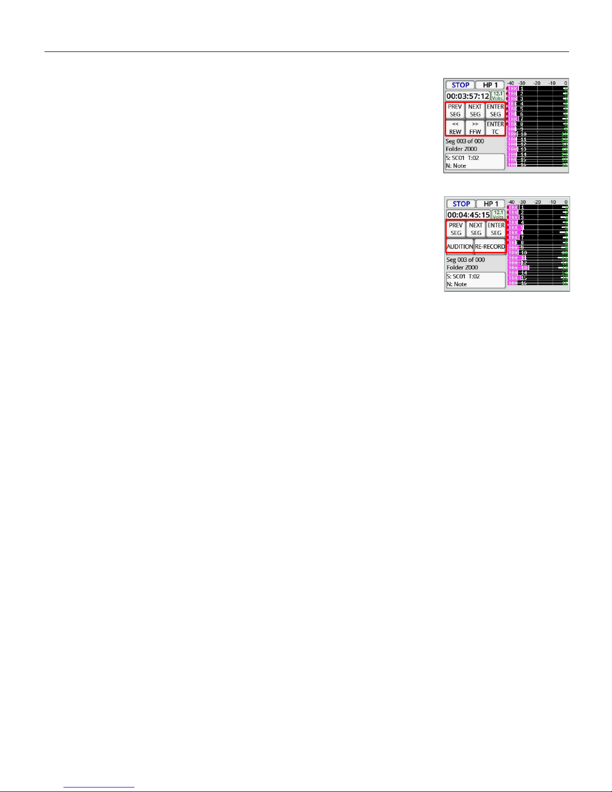
Zaxcom Deva 24 Pressing the Cue Key
50
Pressing the Cue Key
Tapping on the CUE key will open the playback navigation keys on the home screen.
Using the keys allows for navigating to specific segments, or to a specific time code.
Tapping on the CUE key a second time will open the audition and re-record feature.
The re-record feature allows for simultaneous playback from all Zaxcom wireless
transmitters so that a scene can be remixed.
Either a specific segment can be replayed or a time code in-point can be entered.
Re-record will create an additional remixed file with time code that will match the
original file.
Pressing the AUDITION key will playback the wireless sources but not record them.
Pressing the RE-RECORD key will playback the wireless sources while Deva 24 records
the new mix as a separate file.
Page 51

Zaxcom Deva 24 Pressing the TC Key
51
Pressing the Time Code Key
• Press the TC key once will open the time code menu.
• Press the TC key a second time will open the on screen TC slate.
Manually entering time code and user bits
Tap on either the ENTER TIME CODE key / ENTER USER BITS key or tap on the
GENERATOR TC / GENERATOR UB keys to open a numeric keyboard where the time
code / user bits can be entered.
Setting the TC out and TC display source
These keys sets what time code source Deva 24 will output from the time code out
BNC connector, and what time code source will be displayed on the screen.
• GENERATOR - The time code will originate from Deva’s internal time code
generator.
• CARD - The time code will originate from the file that is being recorded or playing
back.
• GEN-STOP - Only for time code display - When Deva24 is recording the time code
displayed will be from the internal timecode generator, but the time code displayed
will freeze on the stopped point when the transport is stopped.
Setting the TC mode
• FREE-RUN - Time code will free run continuously.
• REC-RUN - Time code will start to run when Deva 24 begins to record and will stop
when recording stops.
• CJAM TC/UB - Time code and user bits are continuously updated from a connected
external source and not Deva’s internal time code generator.
• CJAM TC - Time code only is continuously updated from a connected external
source and not Deva’s internal time code generator.
• CJAM UB - User bits only are continuously updated from a connected external
source.
Setting the TC Frame Rate
Tapping on the FRAME RATE key will cycle through the time code frame-rates.
Deva 24 supports all standard SMPTE frame-rates: 23.98, 24, 25, 29.97, 29.97DF, 30,
30DF
Enabling increment user bits
If the incremental user-bits is set to ON the user bits will automatically increase with
each take to the next number or letter.
Page 52

Zaxcom Deva 24 Pressing the TC Key
52
Jamming time code and user bits
These keys are used to jam Deva 24’s time code and user bits.
• JAM TC - Jams time code from an external source, such as a camera or a master
time code unit.
• JAM DATE - The user bits are created from Deva 24’s internal calendar.
• JAM UB - Jams user bits from an external source, such as a camera or a master
time code unit.
• JAM TIME - Time code is created from Deva 24’s internal clock.
Displaying the time code slate
Pressing the TC key a second time opens a visual time code slate. The slate is used to
provide a visual sync for cameras so the picture can be synced to sound.
Please note the TC slate can be inverted by going to the SETUP menu > MODES > set
TC SLATE to “FLIPPED”.
When the time code slated is displayed pressing the MENU knob will freeze the time
code display will freeze and a 1-frame beep tone will be sent to any bus that has tone
routed to an output.
Page 53

Zaxcom Deva 24 Pressing the Input Key
53
Pressing the Input Key
Pressing the INPUT key will open the input configure menu - see the input configure
section of this manual on page 31.
Page 54

MAIN MENU Pressing the Scene / Take / Note Key
54
Pressing the Scene / Take / Note Key
Pressing the SCENE / TAKE / NOTE keys will open the on screen keyboard for that
selection so the metadata can be entered.
Page 55

MAIN MENU Metadata Entry
55
Metadata
Tapping on the metadata display on the lower right hand corner of the home screen will open
the metadata management menu.
Entering metadata
Tapping on the SCENE, TAKE, or NOTE key will open a keyboard where the information for
those items can be entered or adjusted.
Increasing the scene number
Tapping the INC SCENE key will advance the scene to the next number / letter.
Resetting the take
Tapping the RESET TAKE key will reset the take to 1.
Storing a note preset
After a note has been entered in the NOTE field, tapping on the STORE NOTE key will
highlight the note preset list. Then tap on the desired preset position to save the note to.
Clearing the note field
Tapping the CLEAR NOTE key will clear the note field.
Page 56

MAIN MENU Metadata Entry
56
Navagating the folder
Tapping the SEGMENT key will turn the key orange and the menu encoder can be used to
scroll thru the metadata for each segment in the selected folder
Tapping the ARROW keys will advance or back thru the segments for the selected folder.
Viewing the preset note list
Tapping the ALL NOTES key will open the preset note list.
Page 57

NOMAD OPERATIONS Recording Media
57
SATA Drives / Compact Flash Cards
Currently we recommend using SanDisk or Transcend media. Any size compact flash card up to 128GB; and any
size SATA drive, up to a terabyte will be fine. For normal operation it is not necessary to used fast speed cards as
it will not make Deva 24 write any faster.
We do not advise using Lexar, Kingston, Delkin or off brand media from questionable manufacturers. And please
only buy media from reliable sources and avoid questionable retailers, because counterfeit media exist and can
be unreliable and can cause crashing.
It is recommended to test all media before use, even if it is a brand/size that has used in the past. To test simply
preform a record test for 15 to 20 minutes, If Deva 24 stops recording it is most likely a result of bad media.
Page 58

Zaxcom Deva 24 Syncing to a Denecke Slate
58
Syncing Deva 24 to a Denecke Slate
The LTC stream out of the Deva has a “jitter” in the time code signal at 29.97 fps and 23.976 fps. This can result
in the Denecke TS-C or the TS-3 slates identifying the wrong code, if the slate is set to “Auto Set” (Position 5). In
addition if “Auto Set” is used the slate can experience a time code drift.
So when setting the slate to receive time code at 29.97 or 23.976, do not use the auto set mode. Just simply set
the rotary dial to the corresponding time code frame rate. When syncing the slate “Sync Err” will be displayed.
Simply ignore this. The slate will accept the sync and the slate and Deva will stay in perfect sync with each other.
Page 59

Zaxcom Deva 24 Wiring Configuration
Deva 24 Connector Assignments
Audio Input / Output Connectors (XLR-3)
Pin 1 - Ground
Pin 2 - Signal (+)
Pin 3 - Signal (-)
Audio Input / Output Connectors (TA-5)
Pin 1 - Ground
Pin 2 - Channel A (Left) ( + )
Pin 3 - Channel A (Left) ( - )
Pin 4 - Channel B (Right) ( + )
Pin 5 - Channel B (Right) ( - )
Mono & Tappe Output Connectors (1/8” TRS or 1/8”TS)
Tip - +
Ring - N/C
Sleeve - Ground
Slate Microphone Input Connector (1/8” TRS)
This is a balanced input and can be used with dynamic microphones. It can also be used unbalanced with low voltage
microphones.
Tip - ( + ) / Hot - Biased to 5 Volts
Ring - ( - ) / Cold - Biased to 5 Volts
Sleeve - Ground
Headphone Output Connectors (1/4” TRS or 1/8” TRS)
Tip - Signal Left
Ring - Signal Right
Sleeve - Signal ground
Power Connectors (Hirose-4 Connector)
Pin 1 - Ground ( - )
Pin 2 - Not Connected
Pin 3 - Not Connected
Pin 4 - DC ( + )
Com 1 / GPI Remote Roll (DB9)
Pin 1 - RS422 In
Pin 2 - GPI Out
Pin 3 - Word Clock Out
Pin 4 - GPI In
Pin 5 - Ground
Pin 6 - RS422 In
Pin 7 - 5V Out
Pin 8 - RS422 Out
Pin 9 - RS422 Out
59
Page 60

Zaxcom Deva 24 Wiring Configuration
AES
INPUT
Input 1/2 ( + )
24
Input 1/2 ( – )
12
Input 3/4 ( + )
10
Input 3/4 ( – )
23
Input 5/6 ( + )
21
Input 5/6 ( – )
9
Input 7/8 ( + )
7
Input 7/8 ( – )
20
Input 9/10 ( + )
18
Input 9/10 ( – )
6
Input 11/12 ( + )
4
Input 11/12 ( – )
17
Input 13/14 ( + )
15
Input 13/14 ( – )
3
Input 15/16 ( + )
1
Input 15/16 ( – )
14
Ground pins 2, 5, 8, 11, 16, 19, 22, 25
AES In 1 thru 16 (DB25)
All inputs support AES 42
DB25 PIN NUMBER
60
Page 61

Zaxcom Deva 24 Wiring Configuration
AES ISO
OUTPUT
Direct Out 1/2 ( + )
24
Direct Out 1/2 ( – )
12
Direct Out 3/4 ( + )
10
Direct Out 3/4 ( – )
23
Direct Out 5/6 ( + )
21
Direct Out 5/6 ( – )
9
Direct Out 7/8 ( + )
7
Direct Out 7/8 ( – )
20
Direct Out 9/10 ( + )
18
Direct Out 9/10 ( – )
6
Direct Out 11/12 ( + )
4
Direct Out 11/12 ( – )
17
Ground pins 2, 5, 8, 11, 16, 19, 22
AES Direct Out 1 thru 12 (DB25)
These are direct (pre equalization) ISO outputs of the 12 analog inputs
DB25 PIN NUMBER
61
Page 62

Zaxcom Deva 24 Wiring Configuration
AES
INPUT / OUTPUT
Input 17/18 ( + )
24
Input 17/18 ( – )
12
Input 19/20 ( + )
10
Input 19/20 ( – )
23
Input 21/22 ( + )
21
Input 21/22 ( – )
9
Input 23/24 ( + )
7
Input 23/24 ( – )
20
Output Bus 1/2 ( + )
18
Output Bus 1/2 ( – )
6
Output Bus 3/4 ( + )
4
Output Bus 3/4 ( – )
17
Output Bus 5/6 ( + )
15
Output Bus 5/6 ( – )
3
Output Bus 7/8 ( + )
1
Output Bus 7/8 ( – )
14
Ground pins 2, 5, 8, 11, 16, 19, 22, 25
AES In 17 thru 24 / AES Out Buses 1 thru 8 (DB25)
These inputs do not support AES 42
DB25 PIN NUMBER
62
Page 63

Zaxcom Deva 24 Updating Firmware
Updating Firmware
Each Deva 24 is shipped with the latest firmware version installed. When newer firmware becomes available, it can be
downloaded from the Zaxcom website: http://www.zaxcom.com/software-updates
Newer version of beta software may be found on the Zaxcom Forums: http://www.zaxcom.com/forum
How to updating Deva 24 firmware
1. Format a compact flash card in the Deva 24 Compact Flash 1 slot.
2. Download the Deva 24 zip file and extract the Deva 24 program (.BIN) file.
3. Copy the .BIN file on to the formatted card and insert it back into the CF1 slot on the Deva 24.
4. After the Deva 24 is booted up - press the SHIFT key while pressing the F5 key.
5. Deva 24 will indicate its progress on the screen - the update will take approximately 4 minutes.
Please note it is important that the Deva 24 does not lose power during the update.
6. After the update is complete power cycle the Deva and verify that it’s running the new software (see the About
Deva menu)
63
Page 64

Zaxcom Deva 24 Support
Product Support
Register your product with Zaxcom: http://zaxcom.com/support/product-registration/
Download the latest Firmware from: http://zaxcom.com/support/updates/
Download the latest User Manuals from: http://zaxcom.com/support/updates/
Submit Technical Questions at: http://www.zaxcom.com/submit-a-technical-question
Submit information for Repair Services at: http://www.zaxcom.com/support/repairs
Join the Zaxcom User Forum at: http://www.zaxcom.com/forum/forum.php
Join the Zaxcom Face Book User Group at: https://www.facebook.com/groups/682199065139938/
64
Page 65

Zaxcom Deva 24 Specifications
Deva 24 Specifications
Analog In
12 Mic/line-level with NeverClip™ 48V phantom power & 4 line-level (camera return or mix inputs)
Connectors: 6 x XLR-3F & 5 x TA5 (two inputs per TA5)
Mic level input range: -56 to -26 dBu
Line level input range: -20 to +8 dBu
Distortion: 0.0015%
ADC bit-depth: 24 bits
ADC dynamic range: 136 dB
Clipping level: +28 dBu
Frequency response: 20 Hz to 22 kHz (48 kHz sampling-rate)
THD + noise: 0.0015%
Slate mic input: External balanced / unbalanced with +5V bias
Analog Out
4 Balanced XLR, 0dBu, -10dBu and -30dBu
3 Balanced TA5 (two outputs per TA5) 0dBu, -10dBu and -30dBu
Tape/mono output: 2 unbalanced 3.5mm adjustable from -12dBu to 20dBu
Headphone 1: 1/4 inch and 3.5mm (front panel) stereo bus
Headphone 2: 3.5mm stereo bus
Output level: 0 dBu @ -20 dBFS
Clipping level: +20 dBu
DAC Bit-depth: 24 Bits
DAC Dynamic Range: 115dB
Impedance: 30 ohm
Digital In
Digital Inputs: 24 (8 AES/AES42 pair with SRC)
Connector: DB-25 female
Digital Out
Bus output channel count: 4 AES pairs (8 channels)
AES direct out: 6 AES pairs (12 channels processor independent)
Connector: DB-25 female
Recording
Track count: 24 (16 ISO tracks + 8 mix or ISO tracks)
Bit-depth (primary): 24 bits
Bit-depth (mirror): 24 bits
Sample rates (kHz): 48, 48.048
Head room: 12 to 20 dB (NeverClip extends analog dynamic range
Primary Format: MARF II / .ZAX
Mirror Format: FAT32 / BWF-P, BWF-M
Max Pre-record duration: up to 10 seconds
MixAhead™: .5 seconds max in 10mS steps
2 simulations mirror media
Data Storage
Primary Media: 2.5" SanDisk SSD drive
Mirror Media: 2 x CF Card slots, eSATA port
(2 media simultaneous mirror)
65
Page 66

Zaxcom Deva 24 Specifications
Internal Mixer
Mixer Type: 32 bit floating point DSP
Recording track mix bus: 8
ISO track routing: 16 tracks + 8 when a single source is routed to a mix bus
Stereo headphone busses: 2
Busses: 10 (including headphone output x 2)
Mixer Cross Point: 32 input x 16 output (Pre-fader / Post-fader / Phase Inversion)
A-D / D-A resolution: 24 bit
Head room: Selectable 12 to 20 dB
Output bus delay: 0 to 100mS in 1mS steps
Effects
Delay: 0 to 60mS in .1mS steps
3 Band shelving filter EQ
Notch filter: 2 band, 20 Hz to 20 kHz frequency range adjustable
Compressor type: Soft knee with side chain
High Pass Filter: 20 Hz to 230 Hz
Timecode Reader/Generator
Timecode Type: SMPTE
Time code Connector: BNC x 2
Input Voltage: 1-4VPP
Output Voltage: 2VPP
Clock Accuracy: 1.54 PPM (1 frame out in 6 hours)
Timecode Frame-rates: 23.98, 24, 25, 29.97NDF, 29.97DF, 30NDF, 30DF
Power
Type: Dual external with auto switching
External Power: 8 to 18 VDC @ 1 amp
Power Connecter: 4-pin Hirose female x 2
Battery Meter: On LCD display
Output power: 4-pin Hirose female (1 amp)
Physical
Size (H x W x D) while looking at screen: 3.0″ x 10.5″ x 7.0″
Weight: 5.4 pounds (with SATA drive)
Miscellaneous
Display: 2.8" full color sunlight readable LCD touch screen
Slate Mic: Internal / External
Serial/RS-422: 3 x 4-Pin USB style
Serial/RS422: 1 DB9 connection
Serial Port: Zaxcom Proprietary
Compatible with Mix-16, Oasis
66
Page 67

Zaxcom Warranty Policy and Limitations
Zaxcom Inc. values your business and always attempts to provide you with the very best service.
No limited warranty is provided by Zaxcom unless your Deva 24 (“Product”) was purchased from an authorized distributer or authorized reseller. Distributers
may sell Product to resellers who then sell Product to end users. Please see below for warranty information or obtaining service. No warranty service is
provided unless the Product is returned to Zaxcom Inc. or a Zaxcom dealer in the region where the Product was first shipped by Zaxcom.
Warranty Policy
The Product carries a Standard Warranty Period of one (1) year.
NOTE: The warranty period commences from the date of delivery from the Zaxcom dealer or reseller to the end user.
There are no warranties which extend beyond the face of the Zaxcom limited warranty. Zaxcom disclaims all other warranties, express or implied, regarding
the Product, including any implied warranties of merchantability, fitness for a particular purpose or non-infringement. In the United States, some laws do not
allow the exclusion of the implied warranties.
Troubleshooting & Repair Services
No Product should be returned to Zaxcom without first going through some basic troubleshooting steps with the dealer you purchased your gear from.
To return a product for repair service, go to the Zaxcom Repair Services page http://www.zaxcom.com/repairs and fill in your information; there is no need
to call the factory for an RMA. Then send your item(s) securely packed (in the original packaging or a suitable substitute) to the address on the repair services
page. Insure the package, as we cannot be held responsible for what the shipper does.
Zaxcom will return the warranty repaired item(s) via two-day delivery within the United States at their discretion. If overnight service is required, a FedEx or
UPS account number must be provided to Zaxcom to cover the shipping charges.
Warranty Limitations
Zaxcom’s limited warranty provides that, subject to the following limitations, each Product will be free from defects in material and workmanship and will
conform to Zaxcom’s specification for the particular Product.
Limitation of Remedies
Your exclusive remedy for any defective Product is limited to the repair or replacement of the defective Product.
Zaxcom may elect which remedy or combination of remedies to provide in its sole discretion. Zaxcom shall have a reasonable time after determining that a
defective Product exists to repair or replace a defective Product. Zaxcom’s replacement Product under its limited warranty will be manufactured from new
and serviceable used parts. Zaxcom’s warranty applies to repaired or replaced Product for the balance of the applicable period of the original warranty or
thirty days from the date of shipment of a repaired or replaced Product, whichever is longer.
Limitation of Damages
Zaxcom’s entire liability for any defective Product shall, in no event, exceed the purchase price for the defective Product. This limitation applies even if
Zaxcom cannot or does not repair or replace any defective Product and your exclusive remedy fails of its essential purpose.
No Consequential or Other Damages
Zaxcom has no liability for general, consequential, incidental or special damages. These include loss of recorded data, the cost of recovery of lost data, lost
profits and the cost of the installation or removal of any Product, the installation of replacement Product, and any inspection, testing or redesign caused by
any defect or by the repair or replacement of Product arising from a defect in any Product.
In the United States, some states do not allow exclusion or limitation of incidental or consequential damages, so the limitations above may not apply to you.
This warranty gives you specific legal rights and you may also have other rights, which vary from state to state.
Your Use of the Product
Zaxcom will have no liability for any Product returned if Zaxcom determines that:
• The Product was stolen.
• The asserted defect:
• Is not present,
• Cannot reasonably be fixed because of damage occurring when the Product is in the possession of someone other than Zaxcom, or
• Is attributable to misuse, improper installation, alteration, including removing or obliterating labels and opening or removing external covers (unless
authorized to do so by Zaxcom or an authorized Service Center), accident or mishandling while in the possession of someone other than Zaxcom.
• The Product was not sold to you as new.
Additional Limitations on Warranty
Zaxcom’s warranty does not cover Product, which has been received improperly packaged, altered or physically abused.
67
 Loading...