

Page 1
Page 2

_________________________________________________________Zaxcom Deva User’s Manual
Table of Contents
TABLE OF FIGURES ............................................................................................................................................. 17
TABLE OF TABLES ............................................................................................................................................... 18
CHAPTER 1 – INTRODUCTION ......................................................................................................................... 19
OVERVIEW .................................................................................................................................................................................................. 19
USER MANUAL CONVENTIONS ................................................................................................................................................................ 19
SYSTEM FEATURES ...................................................................................................................................................................................... 19
Deva-5.8 Specific ....................................................................................................................................................................................................... 19
Deva-16 Specific ........................................................................................................................................................................................................ 19
Common Features ...................................................................................................................................................................................................... 20
WHAT’S INCLUDED WITH THE DEVA-5.8 ................................................................................................................................................ 20
Deva-5.8 Options ....................................................................................................................................................................................................... 20
WHAT’S INCLUDED WITH THE DEVA-16 ................................................................................................................................................. 21
Deva-16 Options ........................................................................................................................................................................................................ 21
DEVA SOFTWARE RECOMMENDATIONS .................................................................................................................................................. 21
MEDIA / ACCESSORY RECOMMENDATIONS ............................................................................................................................................. 21
Hard Disk Drives ....................................................................................................................................................................................................... 21
CompactFlash Cards ................................................................................................................................................................................................. 21
FireWire Devices ........................................................................................................................................................................................................ 22
Harddisk Drive ....................................................................................................................................................................................................... 22
CompactFlash Reader/Drive ................................................................................................................................................................................ 22
Keyboards .................................................................................................................................................................................................................... 22
TOUCHSCREEN INTERFACE ....................................................................................................................................................................... 22
ANALOG INPUTS ........................................................................................................................................................................................ 22
ANALOG INPUT LIMITER ............................................................................................................................................................................ 22
DIGITAL INPUTS ......................................................................................................................................................................................... 22
MIXING ....................................................................................................................................................................................................... 22
RECORDING ............................................................................................................................................................................................... 22
CAMERA / LINE IN CONNECTOR.............................................................................................................................................................. 22
Deva-5.8 ....................................................................................................................................................................................................................... 22
Deva-16 ........................................................................................................................................................................................................................ 23
METERING ................................................................................................................................................................................................... 23
FIREWIRE PORT.......................................................................................................................................................................................... 23
RF INTERFERENCE PROTECTION .............................................................................................................................................................. 23
TIMECODE .................................................................................................................................................................................................. 23
INPUT SAMPLING-RATE CONVERSION ..................................................................................................................................................... 23
SEQUENCE OF DEVA COMPONENTS ........................................................................................................................................................ 23
PRODUCT SUPPORT ................................................................................................................................................................................... 24
CHAPTER 2 – EXTERIOR DESCRIPTION ......................................................................................................... 25
FRONT PANEL DESCRIPTION .................................................................................................................................................................... 25
LEFT SIDE DESCRIPTION ............................................................................................................................................................................ 27
RIGHT SIDE DESCRIPTION ......................................................................................................................................................................... 29
CHAPTER 3 – SOFTWARE GUIDE .................................................................................................................... 30
BOOT-UP SEQUENCE PAGE ....................................................................................................................................................................... 30
Page Notes ................................................................................................................................................................................................................... 30
Page Level Shortcuts.................................................................................................................................................................................................. 30
Boot Keys ..................................................................................................................................................................................................................... 30
MENU NAVIGATION .................................................................................................................................................................................. 31
INDEX OF NOMAD PAGES ......................................................................................................................................................................... 31
INDEX OF DEVA SCREEN OBJECTS ........................................................................................................................................................... 32
HOME PAGE ................................................................................................................................................................................................ 35
Page Notes ................................................................................................................................................................................................................... 35
Page Level Shortcuts.................................................................................................................................................................................................. 35
2
Page 3

Zaxcom Deva User’s Manual_________________________________________________________
Using the Deva front panel: ................................................................................................................................................................................. 35
Using the Mix-12 embedded keyboard: ............................................................................................................................................................ 36
Using an attached keyboard: ................................................................................................................................................................................ 36
Enter Segment data entry field .............................................................................................................................................................................. 37
Enter Segment data entry field Shortcuts ......................................................................................................................................................... 37
Mode Status button................................................................................................................................................................................................... 37
View button .................................................................................................................................................................................................................. 37
Timecode button ........................................................................................................................................................................................................ 37
Disk icon ....................................................................................................................................................................................................................... 37
Remaining Recording Time field ............................................................................................................................................................................ 37
Battery icon button .................................................................................................................................................................................................... 37
Sampling-rate field ..................................................................................................................................................................................................... 37
Timecode Frame-rate field ...................................................................................................................................................................................... 38
Pre-record Duration field .......................................................................................................................................................................................... 38
Headphone button .................................................................................................................................................................................................... 38
Mirror Drive Status button ...................................................................................................................................................................................... 38
Cur Segs Folder button ............................................................................................................................................................................................. 38
Cur field.................................................................................................................................................................................................................... 38
Segs field ................................................................................................................................................................................................................... 38
Folder field ............................................................................................................................................................................................................... 38
S: T: N: button .......................................................................................................................................................................................................... 39
Input (#) meters & buttons .................................................................................................................................................................................... 39
Solo Mode ................................................................................................................................................................................................................ 39
Arm / Disarm a Recording Track ....................................................................................................................................................................... 39
MAIN MENU PAGE ...................................................................................................................................................................................... 40
Page Notes ................................................................................................................................................................................................................... 40
Page Level Shortcuts.................................................................................................................................................................................................. 40
Mode Status button................................................................................................................................................................................................... 40
Disk Mix button .......................................................................................................................................................................................................... 40
Output Mix button ..................................................................................................................................................................................................... 40
Faders button .............................................................................................................................................................................................................. 40
Time Code button ...................................................................................................................................................................................................... 40
Setup button ................................................................................................................................................................................................................ 40
Input Configure button ............................................................................................................................................................................................. 40
My Deva button ......................................................................................................................................................................................................... 41
Cue Mode button ....................................................................................................................................................................................................... 41
Tone button ................................................................................................................................................................................................................. 41
Head Phone Mix button ........................................................................................................................................................................................... 41
Scene Take Note button .......................................................................................................................................................................................... 41
About Deva button .................................................................................................................................................................................................... 41
Additional Functionality ............................................................................................................................................................................................. 41
DISK MIX PAGE ........................................................................................................................................................................................... 42
Page Notes ................................................................................................................................................................................................................... 42
Page Level Shortcuts.................................................................................................................................................................................................. 42
Disk Mix matrix buttons .......................................................................................................................................................................................... 42
Slate buttons ............................................................................................................................................................................................................... 42
Tone buttons ............................................................................................................................................................................................................... 42
Preset button ............................................................................................................................................................................................................... 43
(Analog / Digital) In Toggle button ........................................................................................................................................................................ 43
(Pre- / Post-) Fader button ....................................................................................................................................................................................... 43
-MORE- button ........................................................................................................................................................................................................... 43
Clear All button ........................................................................................................................................................................................................... 43
Phase Invert button ................................................................................................................................................................................................... 43
Limiter Settings button .............................................................................................................................................................................................. 43
Limiting button ............................................................................................................................................................................................................ 44
(Up / Down) Arrow button (Deva-16 only) .................................................................................................................................................... 44
Limit buttons ................................................................................................................................................................................................................ 44
DISK LIMITER SETTINGS PAGE ................................................................................................................................................................... 45
Page Notes ................................................................................................................................................................................................................... 45
Page Level Shortcuts.................................................................................................................................................................................................. 45
3
Page 4

_________________________________________________________Zaxcom Deva User’s Manual
Level meter .................................................................................................................................................................................................................. 45
Gain meter ................................................................................................................................................................................................................... 45
Attack button .............................................................................................................................................................................................................. 45
Attack button Shortcuts ....................................................................................................................................................................................... 45
Decay button ............................................................................................................................................................................................................... 46
Decay button Shortcuts ........................................................................................................................................................................................ 46
Thresh button .............................................................................................................................................................................................................. 46
Thresh button Shortcuts ...................................................................................................................................................................................... 46
Ratio button ................................................................................................................................................................................................................. 46
Ratio button Shortcuts ......................................................................................................................................................................................... 46
Gain button .................................................................................................................................................................................................................. 46
Gain button Shortcuts ........................................................................................................................................................................................... 46
Inc button ..................................................................................................................................................................................................................... 46
Dec button ................................................................................................................................................................................................................... 46
OUTPUT MIX PAGE .................................................................................................................................................................................... 47
Page Notes ................................................................................................................................................................................................................... 47
Page Level Shortcuts.................................................................................................................................................................................................. 47
Output Mix matrix buttons ..................................................................................................................................................................................... 47
Slate buttons ............................................................................................................................................................................................................... 47
Tone buttons ............................................................................................................................................................................................................... 47
Preset button ............................................................................................................................................................................................................... 48
(Analog / Digital) In Toggle button ........................................................................................................................................................................ 48
(Pre- / Post-) Fader button ....................................................................................................................................................................................... 48
-MORE- button ........................................................................................................................................................................................................... 48
Clear All button ........................................................................................................................................................................................................... 48
Phase Invert button ................................................................................................................................................................................................... 48
Limiter Settings button .............................................................................................................................................................................................. 48
Output Limiting button ............................................................................................................................................................................................. 48
Limit buttons ................................................................................................................................................................................................................ 49
Routing Presets button .............................................................................................................................................................................................. 49
Output Routing button .............................................................................................................................................................................................. 49
Play buttons ............................................................................................................................................................................................................. 49
Stop buttons ............................................................................................................................................................................................................ 50
Rec buttons ............................................................................................................................................................................................................. 50
OUTPUT LIMITER SETTINGS PAGE ............................................................................................................................................................. 51
Page Notes ................................................................................................................................................................................................................... 51
Page Level Shortcuts.................................................................................................................................................................................................. 51
Level meter .................................................................................................................................................................................................................. 51
Gain meter ................................................................................................................................................................................................................... 51
Attack button .............................................................................................................................................................................................................. 51
Attack button Shortcuts ....................................................................................................................................................................................... 51
Decay button ............................................................................................................................................................................................................... 52
Decay button Shortcuts ........................................................................................................................................................................................ 52
Thresh button .............................................................................................................................................................................................................. 52
Thresh button Shortcuts ...................................................................................................................................................................................... 52
Ratio button ................................................................................................................................................................................................................. 52
Ratio button Shortcuts ......................................................................................................................................................................................... 52
Gain button .................................................................................................................................................................................................................. 52
Gain button Shortcuts ........................................................................................................................................................................................... 52
Inc button ..................................................................................................................................................................................................................... 52
Dec button ................................................................................................................................................................................................................... 52
OUTPUT ROUTING PRESETS PAGE ............................................................................................................................................................ 53
Page Notes ................................................................................................................................................................................................................... 53
Page Level Shortcuts.................................................................................................................................................................................................. 53
Normal button ............................................................................................................................................................................................................ 53
Play Switches button .................................................................................................................................................................................................. 53
Play Tracks 1-6, 15-16 button (Deva-16 only) ................................................................................................................................................ 53
Play Tracks 1-6, 9-10 button (Deva-5.8 only) .................................................................................................................................................. 53
Play Tracks 9-16 button (Deva-16 only) ............................................................................................................................................................ 53
Play Tracks 3-10 button (Deva-5.8 only) ........................................................................................................................................................... 53
4
Page 5

Zaxcom Deva User’s Manual_________________________________________________________
Mute Play button ........................................................................................................................................................................................................ 53
FADERS PAGE .............................................................................................................................................................................................. 54
Page Notes ................................................................................................................................................................................................................... 54
Page Level Shortcuts.................................................................................................................................................................................................. 54
Input graphic faders .................................................................................................................................................................................................. 54
Input (#) meters & buttons .................................................................................................................................................................................... 54
Arm / Disarm a Recording Track ....................................................................................................................................................................... 54
Fader Assign button ................................................................................................................................................................................................... 54
Lock Faders button .................................................................................................................................................................................................... 54
(KNOB / TOUCH) FADER ASSIGN PAGE ................................................................................................................................................... 55
Page Notes ................................................................................................................................................................................................................... 55
Page Level Shortcuts.................................................................................................................................................................................................. 56
Knob Assign matrix buttons .................................................................................................................................................................................... 56
Touch Fader Assign matrix buttons ...................................................................................................................................................................... 56
Preset button ............................................................................................................................................................................................................... 56
(Analog / Digital) In Toggle button ........................................................................................................................................................................ 56
(Fader / ZaxNet Trim) button ................................................................................................................................................................................ 56
Clear All button ........................................................................................................................................................................................................... 56
Fader Assign Toggle button ..................................................................................................................................................................................... 56
TIMECODE PAGE ......................................................................................................................................................................................... 57
Page Notes ................................................................................................................................................................................................................... 57
Page Level Shortcuts.................................................................................................................................................................................................. 57
Reader T.C. field ......................................................................................................................................................................................................... 57
Reader U.B. field ........................................................................................................................................................................................................ 57
Generator T.C. field ................................................................................................................................................................................................... 57
Generator U.B. field ................................................................................................................................................................................................... 57
Timecode Out button ................................................................................................................................................................................................ 57
Timecode Displayed button ..................................................................................................................................................................................... 58
Timecode Run Mode button ................................................................................................................................................................................... 58
Frame Rate button .................................................................................................................................................................................................... 58
Enter Timecode button ............................................................................................................................................................................................. 58
Enter Timecode button Shortcuts ..................................................................................................................................................................... 58
Enter User Bits button .............................................................................................................................................................................................. 58
Enter User-Bits button Shortcuts ....................................................................................................................................................................... 58
Increment User Bits button ..................................................................................................................................................................................... 58
JAM T.C. button .......................................................................................................................................................................................................... 58
JAM U.B. button ......................................................................................................................................................................................................... 58
JAM Date button ........................................................................................................................................................................................................ 58
JAM Time button ........................................................................................................................................................................................................ 58
DUAL RATE TIMECODE ......................................................................................................................................................................................... 58
TIMECODE RUN MODE PAGE .................................................................................................................................................................... 59
Page Notes ................................................................................................................................................................................................................... 59
Page Level Shortcuts.................................................................................................................................................................................................. 59
Timecode Runmode buttons ................................................................................................................................................................................... 59
Auto JAM Date at Midnight button....................................................................................................................................................................... 59
SETUP PAGE ................................................................................................................................................................................................. 60
Page Notes ................................................................................................................................................................................................................... 60
Page Level Shortcuts.................................................................................................................................................................................................. 60
Sample Rate button .................................................................................................................................................................................................. 60
Record Channels button ........................................................................................................................................................................................... 60
Pre-Record Time button ........................................................................................................................................................................................... 60
Tone Level button ...................................................................................................................................................................................................... 60
Operating Modes button .......................................................................................................................................................................................... 60
Meters button ............................................................................................................................................................................................................. 60
Headphone Options button .................................................................................................................................................................................... 60
Clock button ................................................................................................................................................................................................................ 60
Memory button ........................................................................................................................................................................................................... 61
Mix12 button .............................................................................................................................................................................................................. 61
ZaxNet button ............................................................................................................................................................................................................ 61
5
Page 6

_________________________________________________________Zaxcom Deva User’s Manual
User Interface button ................................................................................................................................................................................................ 61
Service button ............................................................................................................................................................................................................. 61
SAMPLE RATE PAGE .................................................................................................................................................................................... 62
Page Notes ................................................................................................................................................................................................................... 62
Page Level Shortcuts.................................................................................................................................................................................................. 62
Sample-rate buttons .................................................................................................................................................................................................. 62
Sample Rate Reference button .............................................................................................................................................................................. 62
RECORD TRACK SELECT PAGE .................................................................................................................................................................. 63
Page Notes ................................................................................................................................................................................................................... 63
Page Level Shortcuts.................................................................................................................................................................................................. 63
Two Track button ...................................................................................................................................................................................................... 63
Four Track button ...................................................................................................................................................................................................... 63
Tracks Mixed To button ........................................................................................................................................................................................... 63
All Tracks button ........................................................................................................................................................................................................ 63
Tracks to Record buttons ......................................................................................................................................................................................... 63
OPERATING MODE PAGE........................................................................................................................................................................... 64
Page Notes ................................................................................................................................................................................................................... 64
Page Level Shortcuts.................................................................................................................................................................................................. 64
Transport Operation button .................................................................................................................................................................................... 64
GPi1 Remote Roll button ......................................................................................................................................................................................... 64
Serial Remote Roll button ........................................................................................................................................................................................ 64
Serial Port Mode button ........................................................................................................................................................................................... 64
Slate Source button ................................................................................................................................................................................................... 65
B-Format button ......................................................................................................................................................................................................... 65
Command Monitor button ....................................................................................................................................................................................... 65
REMOTE COMMAND MONITOR PAGE...................................................................................................................................................... 66
Page Notes ................................................................................................................................................................................................................... 66
Page Level Shortcuts.................................................................................................................................................................................................. 66
METER MENU PAGE .................................................................................................................................................................................... 67
Page Notes ................................................................................................................................................................................................................... 67
Page Level Shortcuts.................................................................................................................................................................................................. 67
Number of Home Screen Meters button ............................................................................................................................................................ 67
Meter Vertical / Horizontal button ....................................................................................................................................................................... 67
Color Schemes button ............................................................................................................................................................................................... 68
Meter Labels button .................................................................................................................................................................................................. 68
Display Inputs button ................................................................................................................................................................................................ 68
Display Outputs button ............................................................................................................................................................................................ 68
Meter Mode button ................................................................................................................................................................................................... 68
Meter Assigns button ................................................................................................................................................................................................ 68
METER LABELS PAGE ................................................................................................................................................................................... 69
Page Notes ................................................................................................................................................................................................................... 69
Page Level Shortcuts.................................................................................................................................................................................................. 69
Meter (#) Label buttons........................................................................................................................................................................................... 69
Meter (#) Label buttons Shortcuts .................................................................................................................................................................... 69
INPUT METER MENU PAGE ........................................................................................................................................................................ 70
Page Notes ................................................................................................................................................................................................................... 70
Page Level Shortcuts.................................................................................................................................................................................................. 70
Input Level meters ..................................................................................................................................................................................................... 70
OUTPUT METER MENU PAGE .................................................................................................................................................................... 71
Page Notes ................................................................................................................................................................................................................... 71
Page Level Shortcuts.................................................................................................................................................................................................. 71
Output Level meters .................................................................................................................................................................................................. 71
METER ASSIGNMENTS PAGE ....................................................................................................................................................................... 72
Page Notes ................................................................................................................................................................................................................... 72
Page Level Shortcuts.................................................................................................................................................................................................. 72
Meter (#) Assignment buttons ............................................................................................................................................................................... 72
METER (#) ASSIGNMENT PAGE .................................................................................................................................................................. 73
Page Notes ................................................................................................................................................................................................................... 73
Page Level Shortcuts.................................................................................................................................................................................................. 73
6
Page 7

Zaxcom Deva User’s Manual_________________________________________________________
Meter Insertion Point buttons ................................................................................................................................................................................. 73
Channel to Meter buttons ....................................................................................................................................................................................... 73
HEADPHONE OPTIONS PAGE .................................................................................................................................................................... 74
Page Notes ................................................................................................................................................................................................................... 74
Page Level Shortcuts.................................................................................................................................................................................................. 74
Headphone Alarm Tone button ............................................................................................................................................................................. 74
Headphone Mix button ............................................................................................................................................................................................ 74
Mute Unrecorded Tracks button ........................................................................................................................................................................... 74
HEADPHONE MIX PAGE ............................................................................................................................................................................. 75
Page Notes ................................................................................................................................................................................................................... 76
Page Level Shortcuts.................................................................................................................................................................................................. 76
Preset Loaded Name field ....................................................................................................................................................................................... 76
Disk Tracks matrix buttons ..................................................................................................................................................................................... 76
Outputs matrix buttons ............................................................................................................................................................................................ 76
Camera Returns matrix buttons ............................................................................................................................................................................ 76
(Disk Tracks / Outputs / Camera Returns) Toggle button ............................................................................................................................. 76
Factory Presets button .............................................................................................................................................................................................. 76
User Presets button ................................................................................................................................................................................................... 76
Toggle On Recorded Tracks button ...................................................................................................................................................................... 77
Phase Invert button ................................................................................................................................................................................................... 77
FACTORY PRESETS PAGE ............................................................................................................................................................................ 78
Page Notes ................................................................................................................................................................................................................... 78
Page Level Shortcuts.................................................................................................................................................................................................. 78
Preset (#) buttons ...................................................................................................................................................................................................... 78
(LOAD / SAVE) USER PRESETS PAGE .......................................................................................................................................................... 79
Page Notes ................................................................................................................................................................................................................... 79
Page Level Shortcuts.................................................................................................................................................................................................. 79
Preset (#) buttons ...................................................................................................................................................................................................... 79
Load/Save Toggle button.......................................................................................................................................................................................... 79
TIME/DATE PAGE ........................................................................................................................................................................................ 80
Page Notes ................................................................................................................................................................................................................... 80
Page Level Shortcuts.................................................................................................................................................................................................. 80
Time field ..................................................................................................................................................................................................................... 80
Date field ...................................................................................................................................................................................................................... 80
Set Time button .......................................................................................................................................................................................................... 80
Set Time button Shortcuts ................................................................................................................................................................................... 80
Set Date button .......................................................................................................................................................................................................... 80
Set Date button Shortcuts ................................................................................................................................................................................... 80
Time mode button ..................................................................................................................................................................................................... 81
Date mode button ..................................................................................................................................................................................................... 81
Daylight Savings Time button ................................................................................................................................................................................. 81
MEMORY PAGE ............................................................................................................................................................................................ 82
Page Notes ................................................................................................................................................................................................................... 82
Page Level Shortcuts.................................................................................................................................................................................................. 82
Restore Factory Defaults button ............................................................................................................................................................................ 82
MIX12 SETUP PAGE .................................................................................................................................................................................... 83
Page Notes ................................................................................................................................................................................................................... 83
Page Level Shortcuts.................................................................................................................................................................................................. 83
Mix-12 Support button............................................................................................................................................................................................. 83
Meter Brightness button .......................................................................................................................................................................................... 83
Tone Button Assign button ...................................................................................................................................................................................... 83
Fader Channel Assignment button ........................................................................................................................................................................ 83
ZAXNET SETUP PAGE ................................................................................................................................................................................ 84
Page Notes ................................................................................................................................................................................................................... 84
Page Level Shortcuts.................................................................................................................................................................................................. 84
ZaxNet Enable button .............................................................................................................................................................................................. 84
Transport Slaved button ........................................................................................................................................................................................... 84
Power Roll button ....................................................................................................................................................................................................... 84
USER INTERFACE SETTINGS PAGE ............................................................................................................................................................. 85
7
Page 8

_________________________________________________________Zaxcom Deva User’s Manual
Page Notes ................................................................................................................................................................................................................... 85
Page Level Shortcuts.................................................................................................................................................................................................. 85
Start-Up Screen button ............................................................................................................................................................................................ 85
Hold Key Time button .............................................................................................................................................................................................. 85
False Start button ....................................................................................................................................................................................................... 85
Default STN Edit Position button .......................................................................................................................................................................... 85
Color Theme button .................................................................................................................................................................................................. 86
Big STN button ........................................................................................................................................................................................................... 86
Backlight Brightness button ..................................................................................................................................................................................... 86
Location button ........................................................................................................................................................................................................... 86
INPUT CONFIGURE PAGE (ANALOG INPUTS SELECTED) ......................................................................................................................... 87
Page Notes ................................................................................................................................................................................................................... 87
Page Level Shortcuts.................................................................................................................................................................................................. 87
Analog (#) buttons ..................................................................................................................................................................................................... 87
(Analog / Digital / Line Lvl) Inputs Toggle button .............................................................................................................................................. 87
High Pass Filter button ............................................................................................................................................................................................. 87
Enabling the Highpass Filter ................................................................................................................................................................................. 87
Mic/Line Level button ................................................................................................................................................................................................ 88
Clear All button ........................................................................................................................................................................................................... 88
Adjust Delay button ................................................................................................................................................................................................... 88
High Pass (#) Hz button ......................................................................................................................................................................................... 88
High Pass (#) Hz button Shortcuts .................................................................................................................................................................... 88
Adjust Trim button ..................................................................................................................................................................................................... 88
ANALOG INPUT (#) PAGE ......................................................................................................................................................................... 89
Page Notes ................................................................................................................................................................................................................... 89
Page Level Shortcuts.................................................................................................................................................................................................. 89
(Mic / Line) Level button .......................................................................................................................................................................................... 89
48V (On / Off) button .............................................................................................................................................................................................. 89
Setting Phantom Power ........................................................................................................................................................................................ 89
Delay button ................................................................................................................................................................................................................ 89
Delay button Shortcuts ......................................................................................................................................................................................... 89
HPF button ................................................................................................................................................................................................................... 90
HPF button Shortcuts ........................................................................................................................................................................................... 90
Limiter (On / Off) button ......................................................................................................................................................................................... 90
Trimmer graphic fader ............................................................................................................................................................................................. 90
Level meter .................................................................................................................................................................................................................. 90
Digital Output button ................................................................................................................................................................................................ 90
Dynamics button ........................................................................................................................................................................................................ 90
EQ button ..................................................................................................................................................................................................................... 90
BUS button .................................................................................................................................................................................................................. 90
Mix12 Input Trim Select button ............................................................................................................................................................................ 90
ANALOG INPUT (#) – DYNAMICS PAGE .................................................................................................................................................. 91
Page Notes ................................................................................................................................................................................................................... 91
Page Level Shortcuts.................................................................................................................................................................................................. 91
Level meter .................................................................................................................................................................................................................. 91
Gain meter ................................................................................................................................................................................................................... 91
Compress (On / Off) button .................................................................................................................................................................................... 91
Attack button .............................................................................................................................................................................................................. 91
Attack button Shortcuts ....................................................................................................................................................................................... 91
Decay button ............................................................................................................................................................................................................... 92
Decay button Shortcuts ........................................................................................................................................................................................ 92
Thresh button .............................................................................................................................................................................................................. 92
Thresh button Shortcuts ...................................................................................................................................................................................... 92
Ratio button ................................................................................................................................................................................................................. 92
Ratio button Shortcuts ......................................................................................................................................................................................... 92
Gain button .................................................................................................................................................................................................................. 92
Gain button Shortcuts ........................................................................................................................................................................................... 92
Copy Compress button ............................................................................................................................................................................................. 92
Inc button ..................................................................................................................................................................................................................... 92
Dec button ................................................................................................................................................................................................................... 93
8
Page 9

Zaxcom Deva User’s Manual_________________________________________________________
ANALOG INPUT (#) – EQ PAGE ............................................................................................................................................................... 94
Page Notes ................................................................................................................................................................................................................... 94
EQ page Level Shortcuts .......................................................................................................................................................................................... 94
EQ Memory view Shortcuts ..................................................................................................................................................................................... 95
(Band / Notch) (#) field ........................................................................................................................................................................................... 95
Level field...................................................................................................................................................................................................................... 95
Level field Shortcuts .............................................................................................................................................................................................. 95
(BYPASSED / INLINE) flag ...................................................................................................................................................................................... 95
Band Type flag ............................................................................................................................................................................................................ 95
Freq field ....................................................................................................................................................................................................................... 95
Freq field Shortcuts ............................................................................................................................................................................................... 95
Q field ............................................................................................................................................................................................................................ 95
Q field Shortcuts .................................................................................................................................................................................................... 95
Equalization graph..................................................................................................................................................................................................... 95
Band (#) buttons ........................................................................................................................................................................................................ 96
Notch (#) buttons ...................................................................................................................................................................................................... 96
Entry Mode button .................................................................................................................................................................................................... 96
ANALOG INPUT (#) – BUS PAGE ............................................................................................................................................................. 97
Page Notes ................................................................................................................................................................................................................... 97
Page Level Shortcuts.................................................................................................................................................................................................. 97
Disk Channel (#) buttons ........................................................................................................................................................................................ 97
Output Channel (#) buttons ................................................................................................................................................................................... 97
INPUT CONFIGURE PAGE (DIGITAL INPUTS SELECTED) .......................................................................................................................... 98
Page Notes ................................................................................................................................................................................................................... 98
Page Level Shortcuts.................................................................................................................................................................................................. 98
Digital (#) buttons ..................................................................................................................................................................................................... 98
(Analog / Digital / Line Lvl) Inputs Toggle button .............................................................................................................................................. 98
High Pass Filter button ............................................................................................................................................................................................. 98
Enabling the Highpass Filter ................................................................................................................................................................................. 98
Clear All button ........................................................................................................................................................................................................... 98
Adjust Delay button ................................................................................................................................................................................................... 99
High Pass (#) Hz button ......................................................................................................................................................................................... 99
High Pass button Shortcuts .................................................................................................................................................................................. 99
Adjust Trim button ..................................................................................................................................................................................................... 99
DIGITAL INPUT (#) PAGE ......................................................................................................................................................................... 100
Page Notes ................................................................................................................................................................................................................. 100
Page Level Shortcuts................................................................................................................................................................................................ 100
Delay button .............................................................................................................................................................................................................. 100
Delay button Shortcuts ....................................................................................................................................................................................... 100
HPF button ................................................................................................................................................................................................................. 100
HPF button Shortcuts ......................................................................................................................................................................................... 100
Trimmer graphic fader ........................................................................................................................................................................................... 100
Level meter ................................................................................................................................................................................................................ 101
Dynamics button ...................................................................................................................................................................................................... 101
EQ button ................................................................................................................................................................................................................... 101
BUS button ................................................................................................................................................................................................................ 101
Mix12 Input Trim Select button .......................................................................................................................................................................... 101
DIGITAL INPUT (#) – DYNAMICS PAGE .................................................................................................................................................. 102
Page Notes ................................................................................................................................................................................................................. 102
Page Level Shortcuts................................................................................................................................................................................................ 102
Level meter ................................................................................................................................................................................................................ 102
Gain meter ................................................................................................................................................................................................................. 102
Compress (On / Off) button .................................................................................................................................................................................. 102
Attack button ............................................................................................................................................................................................................ 102
Attack button Shortcuts ..................................................................................................................................................................................... 102
Decay button ............................................................................................................................................................................................................. 102
Decay button Shortcuts ...................................................................................................................................................................................... 103
Thresh button ............................................................................................................................................................................................................ 103
Thresh button Shortcuts .................................................................................................................................................................................... 103
Ratio button ............................................................................................................................................................................................................... 103
9
Page 10

_________________________________________________________Zaxcom Deva User’s Manual
Ratio button Shortcuts ....................................................................................................................................................................................... 103
Gain button ................................................................................................................................................................................................................ 103
Gain button Shortcuts ......................................................................................................................................................................................... 103
Copy Compress button ........................................................................................................................................................................................... 103
Inc button ................................................................................................................................................................................................................... 103
Dec button ................................................................................................................................................................................................................. 103
DIGITAL INPUT (#) – EQ PAGE ............................................................................................................................................................... 104
Page Notes ................................................................................................................................................................................................................. 104
EQ page Level Shortcuts ........................................................................................................................................................................................ 104
EQ Memory view Shortcuts ................................................................................................................................................................................... 105
(Band / Notch) (#) field ......................................................................................................................................................................................... 105
Level field.................................................................................................................................................................................................................... 105
Level field Shortcuts ............................................................................................................................................................................................ 105
(BYPASSED / INLINE) flag .................................................................................................................................................................................... 105
Band Type flag .......................................................................................................................................................................................................... 105
Freq field ..................................................................................................................................................................................................................... 105
Freq field Shortcuts ............................................................................................................................................................................................. 105
Q field .......................................................................................................................................................................................................................... 105
Q field Shortcuts .................................................................................................................................................................................................. 105
Equalization graph................................................................................................................................................................................................... 105
Band (#) buttons ...................................................................................................................................................................................................... 105
Notch (#) buttons .................................................................................................................................................................................................... 106
Entry Mode button .................................................................................................................................................................................................. 106
DIGITAL INPUT (#) – BUS PAGE ............................................................................................................................................................. 107
Page Notes ................................................................................................................................................................................................................. 107
Page Level Shortcuts................................................................................................................................................................................................ 107
Disk Channel (#) buttons ...................................................................................................................................................................................... 107
Output Channel (#) buttons ................................................................................................................................................................................. 107
INPUT CONFIGURE PAGE (LINE LVL INPUTS SELECTED) (DEVA-16 ONLY) ........................................................................................ 108
Page Notes ................................................................................................................................................................................................................. 108
Page Level Shortcuts................................................................................................................................................................................................ 108
Line Level Channel buttons ................................................................................................................................................................................... 108
(Analog / Digital / Line Lvl) Inputs Toggle button ............................................................................................................................................ 108
Route Line Lvl Input button ................................................................................................................................................................................... 108
Clear All button ......................................................................................................................................................................................................... 108
(ANALOG / DIGITAL) INPUT DELAY PAGE ............................................................................................................................................. 109
Page Notes ................................................................................................................................................................................................................. 109
Page Level Shortcuts................................................................................................................................................................................................ 109
Channel (#) buttons ................................................................................................................................................................................................ 109
More Delay button .................................................................................................................................................................................................. 109
Less Delay button..................................................................................................................................................................................................... 109
Enter Delay button .................................................................................................................................................................................................. 109
Enter Delay button Shortcuts ........................................................................................................................................................................... 109
Clear Delay button .................................................................................................................................................................................................. 109
Delay Mode button ................................................................................................................................................................................................. 110
Adjusting the Delay .................................................................................................................................................................................................. 110
(ANALOG / DIGITAL) INPUT TRIM PAGE ................................................................................................................................................ 111
Page Notes ................................................................................................................................................................................................................. 111
Page Level Shortcuts................................................................................................................................................................................................ 111
Input (#) Trim fields ................................................................................................................................................................................................ 111
Input (#) Level meters ............................................................................................................................................................................................ 111
Less Gain button....................................................................................................................................................................................................... 111
More Gain button .................................................................................................................................................................................................... 111
Clear Trim button .................................................................................................................................................................................................... 111
Select All button ........................................................................................................................................................................................................ 111
Adjusting the Trim.................................................................................................................................................................................................... 111
MY DEVA PAGE ......................................................................................................................................................................................... 112
Page Notes ................................................................................................................................................................................................................. 112
Page Level Shortcuts................................................................................................................................................................................................ 112
10
Page 11

Zaxcom Deva User’s Manual_________________________________________________________
Internal HD drive button ....................................................................................................................................................................................... 112
Internal HD drive Status button .......................................................................................................................................................................... 112
Mirror Drive button ................................................................................................................................................................................................. 112
Mirror Drive Status button .................................................................................................................................................................................... 112
Mirror Drive Select button ..................................................................................................................................................................................... 112
Firewire Power button ............................................................................................................................................................................................. 112
INTERNAL DISK UTILITIES PAGE .............................................................................................................................................................. 113
Page Notes ................................................................................................................................................................................................................. 113
Page Level Shortcuts................................................................................................................................................................................................ 113
Erase Current Folder button ................................................................................................................................................................................. 113
Current Folder button ............................................................................................................................................................................................. 113
Delete Last Segment button ................................................................................................................................................................................. 113
Format Drive button ................................................................................................................................................................................................ 113
DISK FOLDERS PAGE ................................................................................................................................................................................. 114
Page Notes ................................................................................................................................................................................................................. 114
Page Level Shortcuts................................................................................................................................................................................................ 114
Folder buttons ........................................................................................................................................................................................................... 114
Up Arrow button ...................................................................................................................................................................................................... 114
Sort Order button..................................................................................................................................................................................................... 114
Page Up button ........................................................................................................................................................................................................ 114
Enable Mirror Playback button ............................................................................................................................................................................ 114
Page Down button ................................................................................................................................................................................................... 115
Name Folder button ................................................................................................................................................................................................ 115
Name Folder button Shortcuts ......................................................................................................................................................................... 115
Down Arrow button ................................................................................................................................................................................................. 115
Erase Folder button ................................................................................................................................................................................................. 115
FOLDER “???” CONTENTS PAGE .............................................................................................................................................................. 116
Page Notes ................................................................................................................................................................................................................. 116
Page Level Shortcuts................................................................................................................................................................................................ 116
#:# Segs field ............................................................................................................................................................................................................ 116
Take buttons ............................................................................................................................................................................................................. 116
Up Arrow button ...................................................................................................................................................................................................... 116
Page Up button ........................................................................................................................................................................................................ 116
Enter Seg # button .................................................................................................................................................................................................. 116
Enter Seg # button Shortcuts ............................................................................................................................................................................ 116
Page Down button ................................................................................................................................................................................................... 116
Edit STN (Scene, Take, Note) button ................................................................................................................................................................ 116
Down Arrow button ................................................................................................................................................................................................. 117
FORMAT MENU WARNING PAGE ........................................................................................................................................................... 118
Page Notes ................................................................................................................................................................................................................. 118
Page Level Shortcuts................................................................................................................................................................................................ 118
Format Drive button ................................................................................................................................................................................................ 118
Do Not Format Drive button ................................................................................................................................................................................ 118
FORMATTING DIALOG BOX ..................................................................................................................................................................... 119
Page Notes ................................................................................................................................................................................................................. 119
Page Level Shortcuts................................................................................................................................................................................................ 119
MIRROR DRIVE PAGE ................................................................................................................................................................................ 120
Page Notes ................................................................................................................................................................................................................. 120
Page Level Shortcuts................................................................................................................................................................................................ 120
Segment number data entry field ........................................................................................................................................................................ 120
Segment number data entry field Shortcuts ................................................................................................................................................... 120
File Type button ........................................................................................................................................................................................................ 120
File Resolution button .............................................................................................................................................................................................. 120
Format Drive button ................................................................................................................................................................................................ 120
Tracks to Mirror button ......................................................................................................................................................................................... 120
Folder to Mirror button........................................................................................................................................................................................... 121
Start Seg button ....................................................................................................................................................................................................... 121
End Seg button ......................................................................................................................................................................................................... 121
Mirror Mode button ................................................................................................................................................................................................ 121
11
Page 12

_________________________________________________________Zaxcom Deva User’s Manual
Advanced Options button ...................................................................................................................................................................................... 121
Mirror Drive Status button .................................................................................................................................................................................... 121
MIRROR FILE TYPE PAGE .......................................................................................................................................................................... 122
Page Notes ................................................................................................................................................................................................................. 122
Page Level Shortcuts................................................................................................................................................................................................ 122
File Type buttons ...................................................................................................................................................................................................... 122
Pull Up / Down buttons .......................................................................................................................................................................................... 122
FORMAT MIRROR DRIVE CAUTION PAGE .............................................................................................................................................. 123
Page Notes ................................................................................................................................................................................................................. 123
Page Level Shortcuts................................................................................................................................................................................................ 123
Format Drive FAT32 button .................................................................................................................................................................................. 123
Do Not Format Drive button ................................................................................................................................................................................ 123
TRACKS TO MIRROR PAGE ...................................................................................................................................................................... 124
Page Notes ................................................................................................................................................................................................................. 124
Page Level Shortcuts................................................................................................................................................................................................ 124
Tracks to Mirror buttons ........................................................................................................................................................................................ 124
MIRROR FOLDERS PAGE ........................................................................................................................................................................... 125
Page Notes ................................................................................................................................................................................................................. 125
Page Level Shortcuts................................................................................................................................................................................................ 125
Folder buttons ........................................................................................................................................................................................................... 125
Up Arrow button ...................................................................................................................................................................................................... 125
Sort Order button..................................................................................................................................................................................................... 125
Page Up button ........................................................................................................................................................................................................ 125
Page Down button ................................................................................................................................................................................................... 125
Mirroring Mode button ........................................................................................................................................................................................... 125
Down Arrow button ................................................................................................................................................................................................. 125
ADVANCED MIRROR OPTIONS PAGE ..................................................................................................................................................... 126
Page Notes ................................................................................................................................................................................................................. 126
Page Level Shortcuts................................................................................................................................................................................................ 126
Timecode Offset button ......................................................................................................................................................................................... 126
Write Sound Report button ................................................................................................................................................................................... 126
CUE MODE PAGE ..................................................................................................................................................................................... 127
Page Notes ................................................................................................................................................................................................................. 127
Page Level Shortcuts................................................................................................................................................................................................ 127
Enter Segment data entry field ............................................................................................................................................................................ 127
Enter Segment data entry field Shortcuts ....................................................................................................................................................... 127
Mode Status button................................................................................................................................................................................................. 127
View button ................................................................................................................................................................................................................ 128
Timecode button ...................................................................................................................................................................................................... 128
Disk icon ..................................................................................................................................................................................................................... 128
Remaining Recording Time field .......................................................................................................................................................................... 128
Battery icon button .................................................................................................................................................................................................. 128
Prev Seg button......................................................................................................................................................................................................... 128
Next Seg button ....................................................................................................................................................................................................... 128
Enter Seg button ...................................................................................................................................................................................................... 128
<< REW button ....................................................................................................................................................................................................... 128
>> FFWD button ..................................................................................................................................................................................................... 129
Cue Toggle button ................................................................................................................................................................................................... 129
Set ZaxNet UB button ........................................................................................................................................................................................... 129
Wireless ReRec button ........................................................................................................................................................................................... 129
Wireless Audition button ........................................................................................................................................................................................ 129
Cur Segs Folder button ........................................................................................................................................................................................... 129
Cur field.................................................................................................................................................................................................................. 129
Segs field ................................................................................................................................................................................................................. 129
Folder field ............................................................................................................................................................................................................. 129
S: T: N: button ........................................................................................................................................................................................................ 129
Input (#) meters & buttons .................................................................................................................................................................................. 129
Arm / Disarm a Recording Track ..................................................................................................................................................................... 130
SCENE TAKE NOTE PAGE ........................................................................................................................................................................ 131
12
Page 13

Zaxcom Deva User’s Manual_________________________________________________________
Page Notes ................................................................................................................................................................................................................. 131
Page Level Shortcuts................................................................................................................................................................................................ 131
Enter Segment data entry field ............................................................................................................................................................................ 131
Enter Segment data entry field Shortcuts ....................................................................................................................................................... 131
#:# Segs field ............................................................................................................................................................................................................ 132
Scene button ............................................................................................................................................................................................................. 132
Scene button Shortcuts ...................................................................................................................................................................................... 132
Inc Scene button ....................................................................................................................................................................................................... 132
Take button ............................................................................................................................................................................................................... 132
Take button Shortcuts ........................................................................................................................................................................................ 132
Reset Take button ................................................................................................................................................................................................... 132
Note button ............................................................................................................................................................................................................... 132
Note button Shortcuts ....................................................................................................................................................................................... 132
Store Note button .................................................................................................................................................................................................... 132
Clear Note button .................................................................................................................................................................................................... 132
Segment button ........................................................................................................................................................................................................ 132
Segment button Shortcuts ................................................................................................................................................................................. 132
Left Arrow button ..................................................................................................................................................................................................... 132
Right Arrow button .................................................................................................................................................................................................. 132
Stored Note buttons ................................................................................................................................................................................................ 132
Up Arrow button ...................................................................................................................................................................................................... 133
Down Arrow button ................................................................................................................................................................................................. 133
ABOUT DEVA PAGE.................................................................................................................................................................................. 134
Page Notes ................................................................................................................................................................................................................. 134
Page Level Shortcuts................................................................................................................................................................................................ 134
KEYBOARD PAGE ...................................................................................................................................................................................... 135
Page Notes ................................................................................................................................................................................................................. 135
Page Level Shortcuts................................................................................................................................................................................................ 135
Bsp button .................................................................................................................................................................................................................. 135
Ent button (Enter) .................................................................................................................................................................................................... 135
Shift button ................................................................................................................................................................................................................ 135
Caps button ............................................................................................................................................................................................................... 135
Left Arrow button ..................................................................................................................................................................................................... 135
Right Arrow button .................................................................................................................................................................................................. 136
BATTERY MENU PAGE .............................................................................................................................................................................. 137
Page Notes ................................................................................................................................................................................................................. 137
Page Level Shortcuts................................................................................................................................................................................................ 137
Low Battery Voltage button ................................................................................................................................................................................... 137
Low Battery Voltage button Shortcuts ........................................................................................................................................................... 137
Reset Graph button ................................................................................................................................................................................................. 137
Battery Type field ..................................................................................................................................................................................................... 137
Voltage field ............................................................................................................................................................................................................... 137
Voltage vs. Time graph ........................................................................................................................................................................................... 137
HEADPHONE VOLUME PAGE ................................................................................................................................................................... 138
Page Notes ................................................................................................................................................................................................................. 138
Page Level Shortcuts................................................................................................................................................................................................ 138
Headphone Linear graphic fader ........................................................................................................................................................................ 138
FALSE START DIALOG ............................................................................................................................................................................... 139
Page Notes ................................................................................................................................................................................................................. 139
Page Level Shortcuts................................................................................................................................................................................................ 139
Folder field ................................................................................................................................................................................................................. 139
Segment field ............................................................................................................................................................................................................ 139
Duration field ............................................................................................................................................................................................................ 139
Scene field .................................................................................................................................................................................................................. 139
Take field ................................................................................................................................................................................................................... 139
Mark it button .......................................................................................................................................................................................................... 139
Cancel button ............................................................................................................................................................................................................ 139
Delete it button ........................................................................................................................................................................................................ 139
DEVA SERVICE MENU WARNING PAGE .................................................................................................................................................. 140
13
Page 14

_________________________________________________________Zaxcom Deva User’s Manual
Page Notes ................................................................................................................................................................................................................. 140
Page Level Shortcuts................................................................................................................................................................................................ 140
Software Options button ........................................................................................................................................................................................ 140
Processor Speed button .......................................................................................................................................................................................... 140
Load ProgFile button ................................................................................................................................................................................................ 140
Load From CD-R button ......................................................................................................................................................................................... 140
Burn Program ROM button ................................................................................................................................................................................... 140
DEBUG SCREEN DIALOG BOX ................................................................................................................................................................. 141
Page Notes ................................................................................................................................................................................................................. 141
Page Level Shortcuts................................................................................................................................................................................................ 141
*B AND *P DIAGNOSTIC FLAGS ............................................................................................................................................................. 142
*B Flag ........................................................................................................................................................................................................................ 142
*P Flag ......................................................................................................................................................................................................................... 142
CHAPTER 4 – SETTING UP THE POWER AND AUDIO CONNECTIONS .............................................. 143
POWER ...................................................................................................................................................................................................... 143
Internal Power ........................................................................................................................................................................................................... 143
External Power .......................................................................................................................................................................................................... 143
Battery Display .......................................................................................................................................................................................................... 143
Battery Chemistry ................................................................................................................................................................................................ 143
Setting the Battery Threshold ............................................................................................................................................................................... 143
TIME AND DATE ....................................................................................................................................................................................... 144
ANALOG / DIGITAL AUDIO INPUTS ....................................................................................................................................................... 144
Switching Between Mic- and Line-Level Input (Analog Only) ...................................................................................................................... 145
Enabling the High Pass Filter (Analog / Digital) ............................................................................................................................................. 145
Setting the High Pass Filter value ...................................................................................................................................................................... 145
Setting the High Pass Filter Frequency on Multiple Channels .................................................................................................................... 145
Enabling 48 VDC Phantom Power (Analog Only) .......................................................................................................................................... 145
Adjusting the Trim (Analog / Digital) ................................................................................................................................................................. 145
Adjusting the Trim using the Analog / Digital Input Trim page ................................................................................................................. 145
Adjusting Individual Trim Levels Using the Input (#) page ......................................................................................................................... 146
Adjusting the Delay (Analog / Digital) ............................................................................................................................................................... 146
Adjusting the Delay Using the Input Delay page ........................................................................................................................................... 146
Adjusting the Delay Using the Input (#) page ................................................................................................................................................ 146
ANALOG AUDIO OUTPUTS .................................................................................................................................................................... 146
DIGITAL AUDIO OUTPUTS ...................................................................................................................................................................... 147
CAMERA / LINE IN CONNECTOR............................................................................................................................................................ 147
Deva-5.8 ..................................................................................................................................................................................................................... 147
Deva-16 ...................................................................................................................................................................................................................... 147
Configuring Analog Inputs 9 – 12 (Deva-16 only) ........................................................................................................................................ 147
ASSIGNING INPUTS TO RECORDING TRACKS AND OUTPUTS ............................................................................................................. 148
Assigning Inputs to Recording Tracks ................................................................................................................................................................. 148
Setting the Number of Tracks Recorded ........................................................................................................................................................... 148
Set the Sampling-rate for Recorded Tracks ...................................................................................................................................................... 148
Assign Inputs to Output Channels ....................................................................................................................................................................... 148
OVERVIEW OF INPUT SIGNALS ................................................................................................................................................................ 149
OVERVIEW OF OUTPUT SIGNALS ........................................................................................................................................................... 149
CHAPTER 5 – SETTINGS FOR RECORDING ................................................................................................. 150
STORING THE DATA ................................................................................................................................................................................ 150
Selecting a folder ...................................................................................................................................................................................................... 150
SETTING THE PRE-RECORD DURATION ................................................................................................................................................. 150
SET THE TONE LEVEL AND DESTINATIONS ........................................................................................................................................... 150
Set the Tone output ................................................................................................................................................................................................ 150
Enable the Tone ....................................................................................................................................................................................................... 150
HOME PAGE METERS ................................................................................................................................................................................ 150
Set the Number of Meters .................................................................................................................................................................................... 151
Set the Meter Labels ............................................................................................................................................................................................... 151
Change the Meter’s Appearance ......................................................................................................................................................................... 151
Change the Meter Orientation ......................................................................................................................................................................... 151
14
Page 15

Zaxcom Deva User’s Manual_________________________________________________________
CHAPTER 6 – USING ZAXNET ........................................................................................................................ 155
Meter Color Schemes ......................................................................................................................................................................................... 151
Screen Backlight Brightness .................................................................................................................................................................................. 151
MONITORING WITH HEADPHONES ....................................................................................................................................................... 151
Fader #8..................................................................................................................................................................................................................... 151
Load a Factory Preset ............................................................................................................................................................................................. 152
Build Your Own Headphone Mix (Working Preset) ....................................................................................................................................... 152
Invert Phase ........................................................................................................................................................................................................... 152
Retaining Your Headphone Mix with a User Preset ...................................................................................................................................... 152
Storing the Mix in a User Preset ...................................................................................................................................................................... 152
Loading a Mix Saved in a User Preset.............................................................................................................................................................. 152
Camera Input (Deva-5.8 only) ............................................................................................................................................................................ 152
TIMECODE PAGE ....................................................................................................................................................................................... 154
Timecode Displayed on the Home page ........................................................................................................................................................... 154
Timecode Output ..................................................................................................................................................................................................... 154
Entering User-bit Data ........................................................................................................................................................................................... 154
Entering Timecode ................................................................................................................................................................................................... 154
Frame-rate ................................................................................................................................................................................................................. 154
ZAXNET SETUP ........................................................................................................................................................................................ 155
ZAXNET ENABLE ...................................................................................................................................................................................... 155
SLAVED / NON-SLAVED OPERATION ...................................................................................................................................................... 155
TRANSMITTER GAIN SETUP ...................................................................................................................................................................... 155
WIRELESS AUDITION & WIRELESS RE-RECORD .................................................................................................................................... 156
CHAPTER 7 – NEW SYSTEM CAPABILITIES ................................................................................................ 157
INTRODUCTION ....................................................................................................................................................................................... 157
IMPROVEMENTS ......................................................................................................................................................................................... 157
Power Roll feature .................................................................................................................................................................................................... 157
Folder Recovery function ........................................................................................................................................................................................ 157
New Processor Speed Selection feature ............................................................................................................................................................ 157
Saving and restoring Deva's configuration INI files ........................................................................................................................................ 157
Simultaneous Mirror feature ................................................................................................................................................................................. 158
“Mirror All Folders” feature .................................................................................................................................................................................. 158
KNOWN FIRMWARE ISSUES ..................................................................................................................................................................... 158
CHAPTER 8 – SHORTCUT KEYS ..................................................................................................................... 159
COMMON DATA ENTRY FIELD SHORTCUTS LIST ................................................................................................................................. 159
Keyboard Keys .......................................................................................................................................................................................................... 159
Front Panel Keys ....................................................................................................................................................................................................... 159
COMMON KEYBOARD PAGE SHORTCUTS LIST ..................................................................................................................................... 159
FRONT PANEL SHORTCUTS .................................................................................................................................................................... 159
MIX-12 EMBEDDED KEYBOARD SHORTCUTS ........................................................................................................................................ 160
ATTACHED KEYBOARD SHORTCUTS ..................................................................................................................................................... 160
BOOT-UP SHORTCUTS ............................................................................................................................................................................ 161
Page Level Shortcuts................................................................................................................................................................................................ 161
Boot Keys ................................................................................................................................................................................................................... 161
HOME PAGE SHORTCUTS ........................................................................................................................................................................ 161
Using the Deva front panel: .................................................................................................................................................................................. 161
Using the Mix-12 embedded keyboard: ............................................................................................................................................................ 162
Using an attached keyboard: ................................................................................................................................................................................ 162
DISK LIMITER SETTINGS PAGE SHORTCUTS ............................................................................................................................................ 163
OUTPUT LIMITER SETTINGS PAGE SHORTCUTS ..................................................................................................................................... 163
Attack button Shortcuts .......................................................................................................................................................................................... 163
Decay button Shortcuts .......................................................................................................................................................................................... 163
Thresh button Shortcuts ......................................................................................................................................................................................... 163
Ratio button Shortcuts ............................................................................................................................................................................................ 163
Gain button Shortcuts ............................................................................................................................................................................................. 163
TIMECODE PAGE SHORTCUTS ................................................................................................................................................................. 163
15
Page 16

_________________________________________________________Zaxcom Deva User’s Manual
Enter Timecode button Shortcuts ........................................................................................................................................................................ 163
Enter User Bits button Shortcuts ......................................................................................................................................................................... 164
METER LABELS PAGE SHORTCUTS ........................................................................................................................................................... 164
Meter (#) Label buttons Shortcuts ...................................................................................................................................................................... 164
TIME/DATE PAGE SHORTCUTS ................................................................................................................................................................ 164
Set Time button Shortcuts ..................................................................................................................................................................................... 164
Set Date button Shortcuts ..................................................................................................................................................................................... 164
INPUT CONFIGURE PAGE SHORTCUTS ................................................................................................................................................... 164
High Pass (#) Hz button Shortcuts..................................................................................................................................................................... 164
(ANALOG / DIGITAL / LINELVL) INPUT (#) PAGE SHORTCUTS ............................................................................................................ 164
Delay button Shortcuts ........................................................................................................................................................................................... 164
HPF button Shortcuts .............................................................................................................................................................................................. 164
(ANALOG / DIGITAL) INPUT (#) – DYNAMICS PAGE SHORTCUTS ...................................................................................................... 164
Attack button Shortcuts .......................................................................................................................................................................................... 164
Decay button Shortcuts .......................................................................................................................................................................................... 164
Thresh button Shortcuts ......................................................................................................................................................................................... 165
Ratio button Shortcuts ............................................................................................................................................................................................ 165
Gain button Shortcuts ............................................................................................................................................................................................. 165
(ANALOG / DIGITAL) INPUT (#) – EQ PAGE SHORTCUTS ................................................................................................................... 165
Level field Shortcuts ................................................................................................................................................................................................. 165
Freq field Shortcuts .................................................................................................................................................................................................. 166
Q field Shortcuts ....................................................................................................................................................................................................... 166
EQ Memory view Shortcuts ................................................................................................................................................................................... 166
(ANALOG / DIGITAL) INPUT (#) – BUS PAGE SHORTCUTS ................................................................................................................. 166
(ANALOG / DIGITAL) INPUT DELAY PAGE SHORTCUTS ....................................................................................................................... 166
Enter Delay button Shortcuts ............................................................................................................................................................................... 166
DISK FOLDERS PAGE SHORTCUTS ........................................................................................................................................................... 166
Name Folder button Shortcuts ............................................................................................................................................................................. 166
FOLDER “???” CONTENTS PAGE SHORTCUTS ........................................................................................................................................ 166
Enter Seg # button Shortcuts ............................................................................................................................................................................... 166
MIRROR DRIVE PAGE SHORTCUTS .......................................................................................................................................................... 166
Start Seg field Shortcuts ......................................................................................................................................................................................... 166
End Seg field Shortcuts ........................................................................................................................................................................................... 166
CUE MODE PAGE SHORTCUTS ................................................................................................................................................................ 167
Enter Segment data entry field Shortcuts ......................................................................................................................................................... 167
SCENE TAKE NOTE PAGE SHORTCUTS .................................................................................................................................................. 167
Enter Segment data entry field Shortcuts ......................................................................................................................................................... 167
Scene button Shortcuts ........................................................................................................................................................................................... 167
Take button Shortcuts ............................................................................................................................................................................................ 167
Note button Shortcuts ............................................................................................................................................................................................ 167
Segment button Shortcuts ..................................................................................................................................................................................... 167
BATTERY MENU PAGE SHORTCUTS ........................................................................................................................................................ 167
Low Battery Voltage button Shortcuts ................................................................................................................................................................ 167
HEADPHONE VOLUME PAGE SHORTCUTS ............................................................................................................................................. 168
DEBUG SCREEN (1967) PAGE SHORTCUTS ........................................................................................................................................... 168
CHAPTER 9 – EQUIPMENT SPECIFICATIONS ............................................................................................. 169
CHAPTER 10 – CONNECTOR PINOUTS ....................................................................................................... 173
POWER CONNECTOR (XLR-4) ............................................................................................................................................................. 173
HEADPHONE OUTPUT CONNECTOR (1/4” STEREO PLUG) ................................................................................................................. 173
ANALOG INPUT / OUTPUT CONNECTORS (XLR-3) ........................................................................................................................... 174
ANALOG OUTPUT CONNECTOR (DB-25) ........................................................................................................................................... 175
SERIAL/GPI CONNECTOR (DB-9) .......................................................................................................................................................... 175
LINE IN / CAMERA CONNECTOR (HIROSE-10) ..................................................................................................................................... 176
Deva-5.8 ..................................................................................................................................................................................................................... 176
Deva-16 ...................................................................................................................................................................................................................... 176
TIMECODE CONNECTOR (LEMO-5) ..................................................................................................................................................... 177
AES DIGITAL INPUT / OUTPUT CONNECTORS (DB-15)..................................................................................................................... 177
16
Page 17

Zaxcom Deva User’s Manual_________________________________________________________
CHAPTER 11 – FIRMWARE INFORMATION ................................................................................................. 178
FIRMWARE ................................................................................................................................................................................................. 178
Advantages to Upgrading the Firmware ............................................................................................................................................................ 178
Upgrading the Firmware in Each Unit ............................................................................................................................................................... 178
FIRMWARE HISTORY ................................................................................................................................................................................ 180
CHAPTER 12 – ZAXCOM WARRANTY POLICY AND LIMITATIONS ..................................................... 183
Table of Figures
FIGURE 2-1 FRONT PANEL IMAGE .................................................................................................................................................................25
FIGURE 2-2 LEFT SIDE IMAGE .........................................................................................................................................................................27
FIGURE 2-3 DEVA-16 & DEVA-5.8 RIGHT SIDE IMAGES ..............................................................................................................................29
FIGURE 3-1 BOOT-UP SEQUENCE PAGE ........................................................................................................................................................30
FIGURE 3-2 HOME PAGE .................................................................................................................................................................................35
FIGURE 3-3 MAIN MENU PAGE ......................................................................................................................................................................40
FIGURE 3-4 DISK MIX PAGE ...........................................................................................................................................................................42
FIGURE 3-5 DISK MIX – LIMITER COLUMN PAGE ..........................................................................................................................................44
FIGURE 3-6 DISK LIMITER SETTINGS PAGE ....................................................................................................................................................45
FIGURE 3-7 OUTPUT MIX PAGE .....................................................................................................................................................................47
FIGURE 3-8 OUTPUT MIX – LIMIT COLUMN PAGE .......................................................................................................................................49
FIGURE 3-9 OUTPUT MIX – OUTPUT ROUTING COLUMNS PAGE ..............................................................................................................49
FIGURE 3-10 OUTPUT LIMITER SETTINGS PAGE ...........................................................................................................................................51
FIGURE 3-11 OUTPUT ROUTING PRESETS PAGE ..........................................................................................................................................53
FIGURE 3-12 TOUCH FADER PAGE ................................................................................................................................................................54
FIGURE 3-13 KNOB / TOUCH FADER ASSIGN PAGE ....................................................................................................................................55
FIGURE 3-14 TIMECODE PAGE .......................................................................................................................................................................57
FIGURE 3-15 TIMECODE RUN MODE PAGE ..................................................................................................................................................59
FIGURE 3-16 SETUP PAGE ...............................................................................................................................................................................60
FIGURE 3-17 SAMPLE RATE PAGE ...................................................................................................................................................................62
FIGURE 3-18 RECORD TRACK SELECT PAGE ................................................................................................................................................63
FIGURE 3-19 OPERATING MODE PAGE .........................................................................................................................................................64
FIGURE 3-20 COMMAND MONITOR PAGE ...................................................................................................................................................66
FIGURE 3-21 METER MENU PAGE ..................................................................................................................................................................67
FIGURE 3-22 EXAMPLES OF HOME PAGE LAYOUTS ......................................................................................................................................67
FIGURE 3-23 EFFECTS OF THE COLOR SCHEMES BUTTON ..........................................................................................................................68
FIGURE 3-24 METER LABELS PAGE .................................................................................................................................................................69
FIGURE 3-25 INPUT METER MENU PAGE .......................................................................................................................................................70
FIGURE 3-26 OUTPUT METER MENU PAGE ..................................................................................................................................................71
FIGURE 3-27 METER ASSIGNMENTS PAGE .....................................................................................................................................................72
FIGURE 3-28 METER (#) ASSIGNMENT PAGE ................................................................................................................................................73
FIGURE 3-29 HEADPHONE OPTIONS PAGE ..................................................................................................................................................74
FIGURE 3-30 HEADPHONE MIX PAGE (PART 1) ...........................................................................................................................................75
FIGURE 3-31 HEADPHONE MIX PAGE (PART 2) ...........................................................................................................................................76
FIGURE 3-32 FACTORY PRESETS PAGE ..........................................................................................................................................................78
FIGURE 3-33 (LOAD / SAVE) USER PRESETS PAGE ........................................................................................................................................79
FIGURE 3-34 TIME/DATE PAGE ......................................................................................................................................................................80
FIGURE 3-35 MEMORY PAGE ..........................................................................................................................................................................82
FIGURE 3-36 MIX-12 SETUP PAGE .................................................................................................................................................................83
FIGURE 3-37 ZAXNET SETUP PAGE ...............................................................................................................................................................84
FIGURE 3-38 USER INTERFACE SETTINGS PAGE ............................................................................................................................................85
FIGURE 3-39 EFFECTS OF THE COLOR THEME BUTTON..............................................................................................................................86
FIGURE 3-40 EFFECTS OF THE BIG STN BUTTON ........................................................................................................................................86
FIGURE 3-41 INPUT CONFIGURE PAGE (ANALOG INPUTS SELECTED) .......................................................................................................87
FIGURE 3-42 ANALOG INPUT (#) PAGE ........................................................................................................................................................89
FIGURE 3-43 ANALOG INPUT (#) - DYNAMICS PAGE ..................................................................................................................................91
FIGURE 3-44 ANALOG INPUT (#) - EQ PAGE ..............................................................................................................................................94
FIGURE 3-45 ANALOG INPUT (#) - BUS PAGE.............................................................................................................................................97
FIGURE 3-46 INPUT CONFIGURE PAGE (DIGITAL INPUTS SELECTED) .........................................................................................................98
17
Page 18

_________________________________________________________Zaxcom Deva User’s Manual
FIGURE 3-47 DIGITAL INPUT (#) PAGE ...................................................................................................................................................... 100
FIGURE 3-48 DIGITAL INPUT (#) - DYNAMICS PAGE ................................................................................................................................ 102
FIGURE 3-49 DIGITAL INPUT (#) - EQ PAGE ............................................................................................................................................. 104
FIGURE 3-50 DIGITAL INPUT (#) - BUS PAGE ........................................................................................................................................... 107
FIGURE 3-51 INPUT CONFIGURE PAGE (LINE LEVEL INPUTS SELECTED) ................................................................................................. 108
FIGURE 3-52 (ANALOG / DIGITAL) INPUT DELAY PAGE .......................................................................................................................... 109
FIGURE 3-53 (ANALOG / DIGITAL) INPUT TRIM PAGE ............................................................................................................................. 111
FIGURE 3-54 MY DEVA PAGE ...................................................................................................................................................................... 112
FIGURE 3-55 INTERNAL DISK UTILITIES PAGE ............................................................................................................................................ 113
FIGURE 3-56 DISK FOLDERS PAGE .............................................................................................................................................................. 114
FIGURE 3-57 FOLDER “???” CONTENTS PAGE ........................................................................................................................................... 116
FIGURE 3-58 FORMAT MENU WARNING PAGE ......................................................................................................................................... 118
FIGURE 3-59 FORMATTING DIALOG BOX ON TOP OF FORMAT MENU WARNING PAGE ..................................................................... 119
FIGURE 3-60 SCREEN DISPLAY OF THE PRIMARY DRIVE FORMAT PROCESS ............................................................................................ 119
FIGURE 3-61 MIRROR DRIVE PAGE ............................................................................................................................................................. 120
FIGURE 3-62 MIRROR FILE TYPE PAGE ....................................................................................................................................................... 122
FIGURE 3-63 FORMAT MIRROR DRIVE PAGE ............................................................................................................................................. 123
FIGURE 3-64 TRACKS TO MIRROR PAGE.................................................................................................................................................... 124
FIGURE 3-65 MIRROR FOLDERS PAGE ........................................................................................................................................................ 125
FIGURE 3-66 ADVANCED MIRROR OPTIONS PAGE .................................................................................................................................. 126
FIGURE 3-67 CUE MODE PAGE ................................................................................................................................................................... 127
FIGURE 3-68 SCENE TAKE NOTE PAGE ...................................................................................................................................................... 131
FIGURE 3-69 ABOUT DEVA PAGE ............................................................................................................................................................... 134
FIGURE 3-70 GENERIC KEYBOARD PAGE ................................................................................................................................................... 135
FIGURE 3-71 BATTERY MENU PAGE ........................................................................................................................................................... 137
FIGURE 3-72 HEADPHONE VOLUME PAGE ................................................................................................................................................. 138
FIGURE 3-73 FALSE START DIALOG ON TOP OF HOME PAGE .................................................................................................................. 139
FIGURE 3-74 DEVA SERVICE MENU PAGE................................................................................................................................................... 140
FIGURE 3-75 DEBUG SCREEN PAGE ............................................................................................................................................................ 141
FIGURE 10-1 XLR-4F POWER CONNECTOR PIN NUMBERING .............................................................................................................. 173
FIGURE 10-2 HEADPHONE PLUG CONNECTIONS .................................................................................................................................... 173
FIGURE 10-3 XLR-3M (LEFT) AND XLR-3F (RIGHT) AUDIO INPUT & OUTPUT CONNECTOR PIN NUMBERING ............................ 174
FIGURE 10-4 DB-25M ANALOG OUTPUT CONNECTOR PIN NUMBERING .......................................................................................... 175
FIGURE 10-5 MINI DB-9 15M SERIAL/GPI CONNECTOR PIN NUMBERING .......................................................................................... 175
FIGURE 10-6 HIROSE-10M LINE IN / CAMERA CONNECTOR PIN NUMBERING .................................................................................... 176
FIGURE 10-7 LEMO-5M TIMECODE CONNECTOR PIN NUMBERING .................................................................................................... 177
FIGURE 10-8 MINI DB-15M DIGITAL INPUT AND OUTPUT CONNECTORS PIN NUMBERING ............................................................. 177
FIGURE 11-1 FIRMWARE INSTALL PART 1 .................................................................................................................................................. 179
FIGURE 11-2 FIRMWARE INSTALL PART 2 .................................................................................................................................................. 179
Table of Tables
TABLE 3-1 INDEX OF NOMAD PAGES ...........................................................................................................................................................31
TABLE 3-2 DISK ICON COLOR CODE ...........................................................................................................................................................37
TABLE 3-3 INDICATOR DESCRIPTIONS .........................................................................................................................................................42
TABLE 3-4 INDICATOR DESCRIPTIONS .........................................................................................................................................................47
TABLE 3-5 INDICATOR DESCRIPTIONS .........................................................................................................................................................56
TABLE 3-6 INDICATOR DESCRIPTIONS .........................................................................................................................................................97
TABLE 3-7 INDICATOR DESCRIPTIONS ...................................................................................................................................................... 107
TABLE 3-8 MIRROR STORAGE MEDIA FORMAT TIME................................................................................................................................ 123
TABLE 3-9 DISK ICON COLOR CODE ........................................................................................................................................................ 128
TABLE 10-1 XLR-4F PIN DESCRIPTION..................................................................................................................................................... 173
TABLE 10-2 HEADPHONE PLUG PIN DESCRIPTION .................................................................................................................................. 173
TABLE 10-3 XLR-3 PIN DESCRIPTION ....................................................................................................................................................... 174
TABLE 10-4 DB-25M PIN DESCRIPTION ................................................................................................................................................... 175
TABLE 10-5 MINI DB-9M PIN DESCRIPTION ............................................................................................................................................ 175
TABLE 10-6 HIROSE 10-PIN DESCRIPTION ................................................................................................................................................ 176
TABLE 10-7 LEMO-5M PIN DESCRIPTION ................................................................................................................................................ 177
TABLE 10-8 MINI DB-15M PIN DESCRIPTION .......................................................................................................................................... 177
18
Page 19

Zaxcom Deva User’s Manual_______________________________________________________ Chapter 1
Chapter 1 – Introduction
Overview
The Zaxcom Deva is a high-resolution audio mixer and recorder for reality television surround recording and
ENG. Lightweight and power efficient, it replaces multiple mixers and portable recorders that are currently used
to mix audio for recording to camera via RF link or hardwired cable.
The Deva has an extensive software and hardware history based on the continuous refinement of our location
recording technology.
The functions of mixing, recording and audio effects are seamlessly integrated providing features, functionality and
audio quality unobtainable with separate solutions. Deva's eight mix busses are a perfect match for the new
generation of ENG cameras that record four to eight tracks of audio.
The Deva is ideal for use with Holophone™ and SoundField™ microphones.
This section describes the Deva’s physical features and their location.
User Manual Conventions
Throughout this manual, the following conventions are used:
button – refers to an on-screen (VIRTUAL) object that represents a parameter that can be changed
and/or viewed.
CF card – refers to any CompactFlash card that meets the tests outlined in CompactFlash Cards
{p.21}.
cycle – is used when the selection rotates through several different possible selections.
cycle the power – refers to turning power to the unit ‘OFF’, waiting a few seconds and then turning the
power ‘ON’.
default setting – refers to the value that is loaded into the associated parameter, in the event that the
Restore Factory Defaults button {p.82} is pressed. The value is highlighted.
key – refers to a PHYSICAL object on the unit for the Operator to change and/or view a
parameter or to navigate through the menu pages.
(A key) + (B key) – Simultaneously press the two keys.
(key press shortcut sequence) – It is necessary to move through the menu pages to get to the page where
changes are to be made. The most efficient way to indicate this is through the sequence
of keys/buttons to be pressed. For example: (SHIFT + SETUP keys Meters button)
means to simultaneously press the SHIFT and SETUP keys then press the Meters button
in the page that is displayed.
{p.##} – refers to the page number on which the item is described.
toggle – is used when the selection switches between two possible selections.
NOTE: A green NOTE is a helpful hint or bit of information.
IMPORTANT: A blue IMPORTANT note indicates something more important than a green NOTE.
CAUTION: A yellow CAUTION note indicates a situation that, if ignored, could cause a significant problem.
WARNING: A red WARNING note indicates a situation that, if ignored, could cause damage to you, your
equipment and/or your reputation.
System Features
Deva-5.8 Specific
10 recording tracks
10-pin Hirose connector for direct connection to supported cameras
Deva-16 Specific
6 analog outputs
16 recording tracks
10-pin Hirose connector for an additional 4 line-level analog inputs
8 analog outputs
19
Page 20

Chapter 1_______________________________________________________Zaxcom Deva User’s Manual
Common Features
Tracks are recorded onto an internal hard-disk drive
Track archiving is available using:
o Internal CompactFlash™
o Internal DVD-RAM drive
o External FireWire™ 400 device
Bit-depth: 24-bits
Timecode frame-rates available: 23.98, 24, 25, 29.97NDF, 29.97DF, 30NDF, 30DF
Sample-rates available (KB): 44.1, 47.952, 48, 48.048, 88.2, 96, 96.096, 192
8 analog mic / line inputs with 48V phantom power, each 10 mA max
8 digital inputs
8 digital outputs
8 hardware faders
Built-in 16-channel mixer
Mix to disk or outputs, pre- or post-fader, with or without phase inversion
The Deva makes it possible for you to keep your recorded audio on the set, allowing Production to instantly
reference previous recordings. Disputes with Post regarding recording issues can be cleared up immediately and
extra copies of recorded audio can be produced in case of lost, damaged or stolen material.
Record to an external FireWire device without an additional computer.
It can generate 4 versions of AES-31 Broadcast Wave Format files for use in Post:
o Polyphonic – 24-bit
o Polyphonic – 16-bit
o Monophonic – 24-bit
o Monophonic – 16-bit
The Deva offers direct Avid and ProTools compatibility. This saves a tremendous amount of time loading files
for Post Production.
Metadata (Scene, Take, Note, Roll Number) can be entered into the Deva using the touchscreen display, Mix-12
control surface, Cameo mixer or external keyboard. This data is contained within the audio recording and is
transferred with the audio into the Avid Post Production system. All metadata can be easily edited on the Deva
to assure Post gets the correct information for each Take.
The Deva supports the FAT-32 disk format. Archive media created using the Deva is directly accessible using
either Macintosh or Windows computers without the necessity of using third-party software drivers.
Lightweight rugged design
Weight: 7.4 lbs (2.76 kg) without battery
Size, while looking at the screen (H x W x D): 3.78” x 10.8” x 8.1” (96 mm x 274.3 mm x 205.7 mm)
Battery runtime: up to 6 hours on a Lithium-Ion NP1
Full color, backlit graphic liquid crystal display – daylight viewable
What’s included with the Deva-5.8
Hard-disk drive in caddy case (Primary Storage)
CompactFlash slot (Secondary Storage)
Built-in DVD-RAM drive (Archive Storage)
FireWire 400 connection (for External Storage)
AES input/output cables
External 110/220 volt power supply
Effects package (EQ, notch filter, compressor and delay on each channel)
Deva-5.8 Options
CD-ROM containing this PDF User’s Manual
Spare HD caddy case
Deva HD caddy to USB adapter
PortaBrace bag
Six channel analog output cable
Mix-8
Mix-12
20
Page 21

Zaxcom Deva User’s Manual_______________________________________________________ Chapter 1
What’s included with the Deva-16
Hard-disk drive in caddy case (Primary Storage)
CompactFlash slot (Secondary Storage)
Built-in DVD-RAM drive (Archive Storage)
FireWire 400 connection (for External Storage)
AES input/output cables
Channel 9 – 12 analog input cable
External 110/220 volt power supply
Effects package (EQ, notch filter, compressor and delay on each channel)
CD-ROM containing this PDF User’s Manual
Deva-16 Options
Spare HD caddy case
Deva HD caddy to USB adapter
PortaBrace bag
Eight channel analog output cable
Mix-8
Mix-12
Deva Software Recommendations
The currently recommended versions are:
The latest version on the Zaxcom website.
7.52
6.03U
5.44O
WARNING: Do NOT use any version before 5.44O.
Media / Accessory Recommendations
Hard Disk Drives
We currently ship the Western Digital WD1600BEVE 2.5” 160GB drive (they’re currently available on
CompactFlash Cards
Amazon.com).
We recommend SanDisk and Transcend cards. Don’t use cards with “double write speed” features. Any modern
card, 8 GB and larger, should work equally well. Do not use cards from questionable manufacturers as they will
wear out quickly due to the lack of a good wear leveling algorithm.
If you are planning to record at 96 kHz or 192 kHz, choose a card that claims 10 MB per second SUSTAINED
write speed (MAX write speed does NOT count).
Once you have the cards in hand, you should test their ability to keep up with the recording process:
sampling-rates lower than 96 kHz – record all tracks for 10 minutes with pre-record set to 10 seconds at a
higher sampling-rate than you expect to use.
sampling-rates 96 kHz and 192 kHz – record 6 – 8 tracks for 10 minutes with pre-record set to 10 seconds at
the desired sampling-rate.
If the unit kicks out of record, the card could not keep up.
Also, after recording, check how long the Disk icon (on the Home page {p.35}) stays Red after you press the
STOP key. It should stay Red for about 0.5 seconds as it finishes writing the last bit of data to the card. If it stays
Red for 1 second or more, you will want to be careful to not go into record while it is still Red, otherwise the
Deva may become confused (nothing serious, it just may still say Stop in the Home page {p.35} while it’s still
recording with the REC key lit up).
21
Page 22

Chapter 1_______________________________________________________Zaxcom Deva User’s Manual
FireWire Devices
Harddisk Drive
We recommend Lacie drives, at the moment. From the Apple store the G-Tech Mini Drive and Smartdisk Firelite
have been reported to work.
Some FireWire drives may need to have the Firewire Power button cycled to have them recognized. Some nonbus powered drives still require FireWire Power to be ON in order to work reliably.
CompactFlash Reader/Drive
The Lexar FireWire 800 with an 800 400 cable has been reported to work.
Keyboards
Here are our recommendations:
PS/2 keyboard from Cherry Corp: G84-4100LCMUS-2 from www.cherrycorp.com
89-Key Mini-USB Keyboard from Micro Center: 810739 from www.MicroCenter.com
Touchscreen Interface
Deva’s full color touchscreen interface is the key to ultimate functionality. It provides instant control of over 300
mixer cross-points and over 200 user parameters. It’s easy to read in direct sunlight and offers a lock feature to
prevent accidental operation.
Analog Inputs
Deva incorporates eight very low noise, low distortion microphone preamps with 48V phantom power. Many
Emmy® and Oscar® winning productions have been recorded with the Zaxcom preamp. The transformerless
design enhances audio quality by eliminating low frequency distortion common in transformer-based microphone
preamps. Each of the eight inputs can be switched between mic-level and line-level operation and feature a
powerful 48V phantom power supply.
Analog Input Limiter
The Deva's analog input limiter prevents high-level audio from clipping the A/D converter in the analog domain.
Digital Inputs
The Deva has four AES input pairs with sample-rate conversion, allowing each input to have a different samplingrate. This is key on location, where it’s not always possible to lock external AES sources.
Mixing
Deva can mix sixteen inputs to eight output busses and record up to sixteen tracks* on the internal hard-disk
drive. The mixer has infinite routing capability. Any input can be routed to any output pre-fader, post-fader, with
or without the phase inverted. The Mix-12 control surface can also be used to form an all digital location
recording and mixing package.
* Deva-5.8 – maximum 10 tracks, Deva-16 – maximum 16 tracks
NOTE: Deva does all of the mixing, the attached Mix-8 / Mix-12 is a control surface only and does not do any
mixer processing. The connection between the Deva and the Mix-8 / Mix-12 carries control surface
communications only.
Recording
The Deva records to the Primary Drive using the Mobile Audio Recording Format (MARF) II. MARF was
developed to be fault tolerant, ensuring that should power be lost while recording, ALL audio up to that point will
be recoverable. The MARF system and its audio-centric operation have eliminated several of the reliability issues
associated with FAT32 recording.
While the backup process is enabled, the audio files are copied to the Mirror Drive, which is in standard FAT32
format. The Mirror media can be given to Post or copied to any computer.
Camera / Line In Connector
Deva-5.8
The Camera connector (10-pin Hirose) connects directly to the 10-pin Hirose audio connector located on most
cameras, providing a two-channel camera feed (a copy of line outputs 5 & 6) and a mono audio return. In addition,
22
Page 23

Zaxcom Deva User’s Manual_______________________________________________________ Chapter 1
with the appropriate cabling, it can be connected through an STA100/150 Stereo Adapter to a TRX900AA
transmitter to provide a two-channel camera RF link with return audio and timecode transmission.
All audio connections are balanced line-level, which eliminates the mic level ground loop noise common in FM
wireless systems. It outputs the signal at 0 dBu, making it directly compatible with most cameras without the use
of external amplification.
Deva-16
The Line In connector (10-pin Hirose) provides for line-level inputs 9 – 12. When activated they are patched into
and replace digital inputs 1 – 4, respectively.
Metering
The Deva provides metering of all input channels and output busses in four different formats, based on user
preference. Channel metadata is superimposed on meters to aid in meter identification. Signal levels are color
coded to aid in rapid identification of overload conditions. Touching a meter selects individual channels for PFL
solo monitoring.
FireWire Port
The Deva acts as a master to control and supply power for an external FireWire device.
RF Interference Protection
The Deva was designed from the ground up to operate in close proximity to sensitive receivers. Wireless devices
can coexist in the sound bag with the Deva running from the same power source.
Timecode
A full-featured SMPTE timecode interface is standard. All common frame-rates and timecode sampling-rates are
supported. In addition, the Deva includes the auto-load function, allowing the unit to automatically enter Record
and Stop modes based on incoming timecode. Be aware, unlike other manufacturer’s equipment, the Deva’s
timecode clock continues to run and maintain accurate timecode after the power is turned ‘OFF’.
Input Sampling-rate Conversion
The Deva will accept any unlocked AES signal with a sampling-rate of 44.1 to 192 kHz. The dynamic range of the
sample-rate conversion is 124 dB, offering completely transparent conversion of digital audio from one sample-rate
to another.
Sequence of Deva Components
To better aid the user in using and understanding his Deva recorder, the following list describes the Analog to
Analog sequence for each component that sees your audio:
1. Input connector
2. Input Limiter
3. Input Gain
4. Analog-to-Digital Converter
5. Prefader Meter
6. Input Compressor
7. Delay Processor
8. Equalization Processor
9. Linear Fader
10. Digital Input Router
11. Disk Limiter
12. Input Meter
13. Home Meter
14. Recorder Track
15. Digital Output Router
16. Output Fader
17. Output Limiter
18. Output Meter
19. Digital-to-Analog Converter
20. Output Connector
23
Page 24

Chapter 1_______________________________________________________Zaxcom Deva User’s Manual
Obviously, a digital input or output is going to follow the same sequence, bypassing the analog input or output
portion (highlighted), as appropriate.
Product Support
Download the latest Firmware from: http://www.zaxcom.com/software-updates
Download the latest User Manuals from: http://www.zaxcom.com/instruction-manuals
Submit Technical Questions at: http://www.zaxcom.com/submit-a-technical-question
Submit information for Repair Services at: http://www.zaxcom.com/repairs
Join the Zaxcom Forum at: http://www.zaxcom.com/forum
24
Page 25
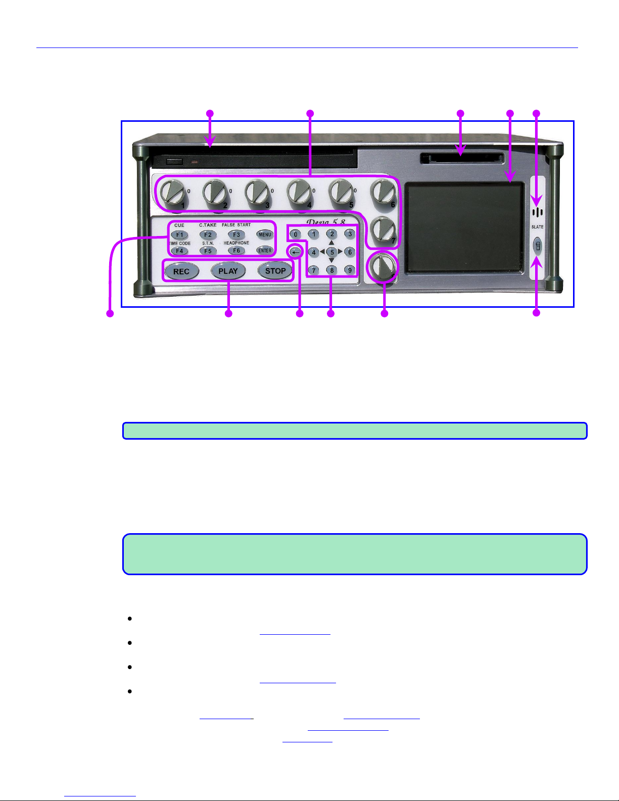
Zaxcom Deva User’s Manual_______________________________________________________Chapter 2
Chapter 2 – Exterior Description
Front Panel Description
1. 2. 3. 4. 5.
6. 7. 8. 9. 10. 11.
Figure 2-1 Front Panel Image
1. Internal DVD Drive
The button will request that the media be eject.
2. Faders 1 – 7
These are seven dedicated hardware faders. Each can be assigned to any channel or combination of channels
in your Deva.
NOTE: For those of you that have wanted to tighten loose faders, it takes a 1.27mm Allen wrench.
3. Internal CompactFlash Media Slot
Pressing the button (on the left side) once puts it in the extended position. Pressing it again will eject the
currently installed CompactFlash card.
4. Color Touchscreen
The touchscreen is the Deva’s main interface. Most selections are made and displayed using it. You can use
either a PDA stylus or your finger to make selections.
NOTE: If you should find the touchscreen freezing (and not because of the temperature), it could be caused
by dust or dirt sneaking in along the edge of the touchscreen. Try sliding a business card around the edge
and gently sweeping out under the bezel.
5. Slate Microphone
6. Function keys
CUE key
Pressing this takes you to the Cue Mode page {p.127}.
C.TAKE key
Pressing this marks the current Take as a Circled Take.
FALSE START key
Pressing this takes you to the False Start dialog {p.139}.
MENU / ESC key
When this key is pressed determines what its action will be:
o While in the Home page {p.35}, it displays the Main Menu page {p.40}.
o While in a parameter page, such as the Sample Rate page {p.62}, it will navigate to the previous page
level. In this example, that is the Setup page {p.60}.
25
Page 26

Chapter 2_______________________________________________________Zaxcom Deva User’s Manual
o While in a data entry field, such as the Meter (#) Label buttons on the Meter Labels page {p.69} and
you’re making a change, it functions as the Escape key by discarding the unsaved change you have started
and closing, in this example, the Keyboard page {p.135} that was opened to make the change.
TIME CODE key
This takes you to the Timecode page {p.57}.
S.T.N. (Scene Take Note) key
Pressing this takes you to the Scene Take Note page {p.131}.
HEADPHONE key
If Fader 8 is assigned to a channel, the first press displays the Headphone Volume page {p.138}.
The next press displays the Headphone Mix page {p.75}.
The next press, the previously displayed page is re-displayed.
ENTER key
This confirms data entry.
7. Transport Control keys
REC key – Sets the operating mode to RECORD
PLAY key – Sets the operating mode to PLAY
STOP key – Sets the operating mode to STOP
NOTE: If the Headphone Alarm Tone button {p.74} is set to ON, pressing the REC key will sound a single
beep in the headphones only. Pressing the STOP key will sound two beeps.
8. SHIFT / BACKSPACE key
This key is used in conjunction with others to perform additional tasks. For example, if it is pressed and held
while pressing one of the Input (#) meters & buttons {p.39}, it allows one or more recording channels to be
armed / disarmed.
9. Numeric keypad
These provide an alternative means of entering numeric data such as timecode, metadata and equalization
values.
10. Headphone volume / Fader 8
This is the eighth fader. When it is not assigned to a channel, it controls the headphone volume. When
assigned to a channel, the headphone volume can be adjusted using the HPH key and the Headphone
Volume page {p.138}.
11. Slate Mic Activation
26
Page 27
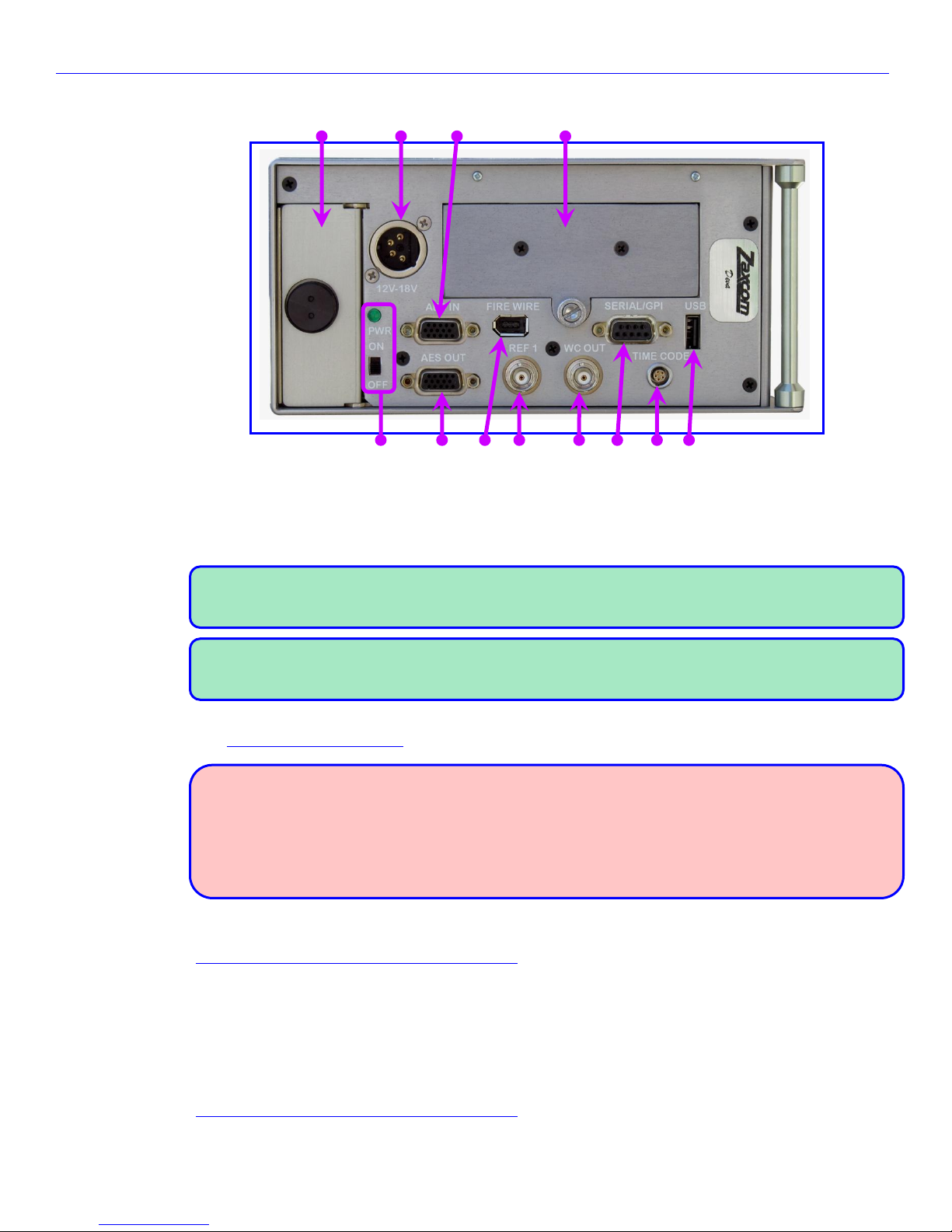
Zaxcom Deva User’s Manual_______________________________________________________Chapter 2
Left Side Description
1. 2. 3. 4.
5. 6. 7. 8. 9. 10. 11. 12.
Figure 2-2 Left Side Image
1. Battery Compartment
The Black knob rotates clockwise to lock the battery compartment door. It will only accept an NP-1 type
battery. You can use Li-Ion or NiMH batteries, as long as you observe the warnings below.
NOTE: It is possible to insert the battery incorrectly. The only indication it is in wrong is the unit will not
power up. To install the battery correctly, turn it so the contact end is facing toward the opening and the
surface with the contacts is turned toward the External Power connector.
NOTE: Consider, once you have inserted the battery and closed the door, pushing the battery ejector pin
on the opposite side just a bit. This will press the battery against the inside of the battery door helping to
keep the door from unlatching and opening-up.
2. External Power connector (XLR-4M)
(See Power Connector (XLR-4) {p.173}.)
WARNINGS:
1) Do NOT install an internal battery with a voltage higher than 16.8 VDC.
2) Do NOT connect the external power connector to a source higher than 18.0 VDC.
Those are the ABSOLUTE upper limits. If you exceed either of these limits by even 0.1 VDC, you will
BLOW the unit’s power supply and require it to be sent in for maintenance. The warranty will be
VOID if it is determined that the power supply was blown by violating either of these warnings.
3. AES (digital) input connector (DE-15 or mini DB-15)
Connect the supplied AES input cable to this connector. The cable provides four pairs of AES input. (See
AES Digital Input / Output Connectors (DB-15) {p.177}.)
4. Hard Disk Drive in Carrier
The carrier holds the Primary Drive where all audio is initially recorded.
5. Power Switch and Power LED
When the power switch is ‘ON’ and power is available, the green LED illuminates.
6. AES (digital) output connector (DE-15 or mini DB-15)
Connect the supplied AES output cable to this connector. The cable provides four pairs of AES output. (See
AES Digital Input / Output Connectors (DB-15) {p.177}.)
27
Page 28

Chapter 2_______________________________________________________Zaxcom Deva User’s Manual
7. IEEE 1394 (FireWire) connector
Connect any FireWire 400 device (external HDD or CD/DVD-RAM drive) here. If required, power for the
device can be turned ‘ON’ from the My Deva page {p.112}.
8. Reference 1 connector (BNC)
Reserved for the future.
9. Wordclock Output connector (BNC)
Connect an external device requiring Wordclock output here.
10. Serial / GPI connector
Connect an external control device, such as the Mix-12 control surface here.
11. Timecode connector (LEMO-5)
(See Timecode Connector (LEMO-5) {p.176}.)
12. USB port
Connect a Zaxcom approved USB keyboard here.
NOTE: What appears to be a USB port is REALLY a PS2 keyboard connector in USB camouflage.
28
Page 29
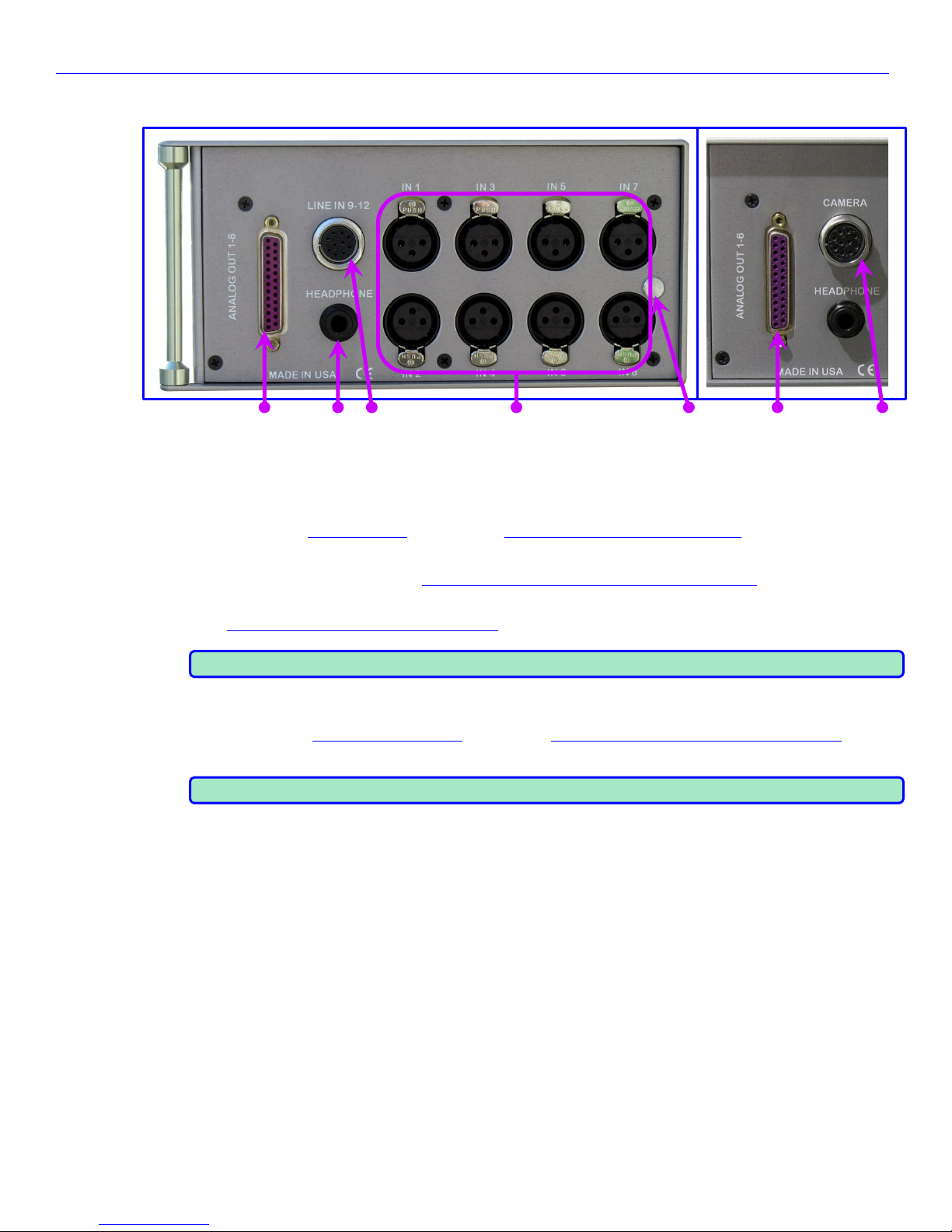
Zaxcom Deva User’s Manual_______________________________________________________Chapter 2
Right Side Description
1. 2. 3. 4. 5. 1. 3.
Deva-16 Right Side Deva-5.8 Right Side Differences
Figure 2-3 Deva-16 & Deva-5.8 Right Side Images
1. Analog Outputs (Deva-16 = 8 channels, Deva-5.8 = 6 channels) (DB-25)
This connector outputs 8 (or 6) channels of line-level audio. You can select the channels assigned to these
outputs from the My Deva page {p.112}. (See Analog Output Connector (DB-25) {p.175})
2. Headphone Output (1/4” stereo jack)
Optimal 100 ohm impedance. (See Headphone Output Connector (1/4” stereo plug) {p.173}.)
3. Line Inputs 9-12 Connector (Deva-16) / Camera Connector (Deva-5.8) (Hirose-10)
(See Line In / Camera Connector (Hirose-10) {p.175}.)
NOTE: For the Deva-5.8, the two return monitor feeds are summed to mono.
4. Mic / Line Inputs 1 through 8 (XLR-3M)
Each balanced input is internally padded to handle either mic-level or line-level signals. The signal level is
selected using the Analog Input (#) page {p.89}. (See Analog Input / Output Connectors (XLR-3)
{p.174}.)
NOTE: Lower headphone impedance results in a higher headphone output level.
5. Battery Ejection Pin
This pin ejects the NP-1 battery from its compartment.
29
Page 30
Chapter 3_______________________________________________________Zaxcom Deva User’s Manual
30
Chapter 3 – Software Guide
The Deva is a very sophisticated recording device. The heart of the system is the software used to operate the
device. This chapter describes every Deva page and the parameters within each.
Boot-up Sequence page
Page purpose: This page shows the processing necessary to initialize the Deva.
How to get here: Turn ‘ON’ the Deva.
=== Ver: vX.XX <MMM DD YYYY HH:MM:SS> ===
SMALL ROM ID=014F IsAtmel=0
CDReadSects:55AA BlockSize=512(15872MB)
INT=0.00V EXT=12.28V FW=12.10V VCC=4.95V
Flash system init…(AudPLD=B)(MainPLD=D)
KEYPRESS = 672
Loading saved settings…
====DSP SPEED = 294.912 ====
Initializing battery backed clock…
Synchronizing clocks…
Initializing audio…
HD S#=SB144GGRKRRE7V
HD Model=Hitachi HTS541616J9AT00
Capacity=137.4 GB
DVD drive test: passed
waiting for Menu key release…
Figure 3-1 Boot-up Sequence page
Page Notes
Referring to Figure 3-1 (above):
The first line indicates information about the firmware version currently installed: the version #, and the date
and time the version was created.
The third line only appears if an internal backup CF card is installed. On the right side, the size of the currently
installed card is displayed (in parentheses). It does NOT indicate the remaining free space on the card.
In the fifth line:
o AudPLD= refers to the hardware revision for the Audio Board. In this example, it is the 2
nd
revision.
o MainPLD= refers to the hardware revision for the Main Processor Board. In this example, it is the 4
th
revision.
The fourth line from the bottom displays the Primary Drive’s capacity.
The second line from the bottom displays the Primary Drive folder currently selected to hold your audio files.
Consider verifying it is correct, as needed.
NOTE: The battery voltage is checked during boot up. If it is less than 9 V, the Deva will ask if you want to
continue. This prevents the Deva from corrupting the current recording folder, should it reboot continuously
with a dying battery.
Page Level Shortcuts
MENU key – Press and hold it to pause the startup sequence until you release it, allowing you to read all of the
information.
Boot Keys
Holding down one of the following keys during bootup changes the Deva’s behavior:
F6 key – causes the Deva (v6.06C or later) to reconstruct corrupted folders. This should allow folders to
be mirrored in the normal way.
0 key – forces 48 kHz mode (in v3.56 and later) (also forces Deva to read corrupted folders).
9 key – enables 192 kHz recording speed. This is somewhat obsolete. The current approach is to run the
DSP in fast mode and enable the 192 kHz selection.
STOP key – forces a restore to factory defaults.
Page 31

Zaxcom Deva User’s Manual_______________________________________________________ Chapter 3
31
Menu Navigation
The Deva uses a high-resolution PDA-style touchscreen to access all software functions. In most cases, you can
use your finger to make selections; however, you may use any PDA stylus.
There are two ways to navigate from page to page. One is to press the MENU key on the front panel. The other
is to touch the Mode Status button at the top right corner of each page. The Mode Status button indicates the
Deva’s current operating mode (Stop, Play or Record).
NOTE: Touching the Mode Status button or pressing the MENU key does not change the Deva’s current mode.
It is safe to make either selection while recording.
Index of Nomad Pages
About Deva page {p.134}
Input Meter Menu page {p.70}
Advanced Mirror Options page {p.126}
Internal Disk Utilities page {p.113}
(Analog / Digital) Input Delay page {p.109}
Keyboard page {p.135}
(Analog / Digital) Input Trim page {p.111}
(Knob / Touch) Fader Assign page {p.55}
Analog Input (#) – BUS page {p.97}
(Load / Save) User Presets page {p.79}
Analog Input (#) – Dynamics page {p.91}
Main Menu page {p.40}
Analog Input (#) – EQ page {p.94}
Memory page {p.82}
Analog Input (#) page {p.89}
Meter (#) Assignment page {p.73}
Battery Menu page {p.137}
Meter Assignments page {p.72}
Cue Mode page {p.127}
Meter Labels page {p.69}
Debug Screen dialog box {p.141}
Meter Menu page {p.67}
Deva Service Menu Warning page {p.140}
Mirror Drive page {p.120}
Digital Input (#) – BUS page {p.107}
Mirror File Type page {p.122}
Digital Input (#) – Dynamics page {p.102}
Mirror Folders page {p.125}
Digital Input (#) – EQ page {p.104}
Mix12 Setup page {p.83}
Digital Input (#) page {p.100}
My Deva page {p.112}
Disk Folders page {p.114}
Operating Mode page {p.64}
Disk Limiter Settings page {p.45}
Output Meter Menu page {p.71}
Disk Mix page {p.42}
Output Mix page {p.47}
Factory Presets page {p.78}
Output Limiter Settings page {p.51}
Faders page {p.54}
Output Routing Presets page {p.53}
False Start dialog {p.139}
Record Track Select page {p.63}
Folder “???” Contents page {p.116}
Remote Command Monitor page {p.66}
Format Menu Warning page {p.118}
Sample Rate page {p.62}
Format Mirror Drive Caution page {p.123}
Scene Take Note page {p.131}
Formatting dialog box {p.119}
Setup page {p.60}
Headphone Mix page {p.75}
Time/Date page {p.80}
Headphone Options page {p.74}
Timecode page {p.57}
Headphone Volume page {p.138}
Timecode Run Mode page {p.59}
Home page {p.35}
Tracks to Mirror page {p.124}
Input Configure page (Analog Inputs selected) {p.87}
User Interface Settings page {p.85}
Input Configure page (Digital Inputs selected) {p.98}
ZaxNet Setup page {p.84}
Input Configure page (Line Lvl Inputs selected)
(Deva-16 only) {p.108}
Table 3-1 Index of Nomad Pages
Page 32

Chapter 3_______________________________________________________Zaxcom Deva User’s Manual
32
Index of Deva Screen Objects
OBJECT NAME PAGE IT APPEARS ON
44100 button Sample Rate page
47952 button Sample Rate page
48000 button Sample Rate page
48048 button Sample Rate page
88200 button Sample Rate page
96000 button Sample Rate page
96096 button Sample Rate page
192000 button Sample Rate page
<< REW button Cue Mode page
>> FFWD button Cue Mode page
About Deva button Main Menu page
Adjust Delay button Input Configure page (Analog Inputs selected)
Adjust Delay button Input Configure page (Digital Inputs selected)
Adjust Trim button Input Configure page (Analog Inputs selected)
Adjust Trim button Input Configure page (Digital Inputs selected)
Advanced Options button Mirror Drive page
All Tracks button Record Track Select page
Alphanumeric buttons Keyboard page
Analog Channel buttons Input Configure page (Analog Inputs selected)
Analog Input (Pre-fader) button Meter (#) Assignment page
Analog Inputs Toggle button Input Configure page (Analog Inputs selected)
Analog/Digital In Toggle button Disk Mix page
Analog/Digital In Toggle button (Knob / Touch) Fader Assign page
Analog/Digital In Toggle button Output Mix page
Analog/Digital Output button Meter (#) Assignment page
Attack button Analog Input (#) – Dynamics page
Attack button Digital Input (#) – Dynamics page
Attack button Disk Limiter Settings page
Attack button Output Limiter Settings page
Audio Gain meter Disk Limiter Settings page
Audio Gain meter Output Limiter Settings page
Audio Input graphic faders Faders page
Audio Level Input meters Input Meter Menu page
Audio Level meter Analog Input (#) page
Audio Level meter Disk Limiter Settings page
Audio Level meter Output Limiter Settings page
Audio Level meters & buttons Cue Mode page
Audio Level meters & buttons Faders page
Audio Level meters & buttons Home page
Audio Level Output meters Output Meter Menu page
Auto Jam Date at Midnight Timecode Run Mode page
Backlight Brightness button User Interface Settings page
Band buttons Analog Input (#) – EQ page
Band buttons Digital Input (#) – EQ page
Band Type flag Analog Input (#) – EQ page
Band Type flag Digital Input (#) – EQ page
Band/Notch # field Analog Input (#) – EQ page
Band/Notch # field Digital Input (#) – EQ page
Battery icon button Cue Mode page
Battery icon button Home page
Battery Type field Battery Menu page
B-Format button Operating Mode page
Big STN button User Interface Settings page
Burn Program ROM button Deva Service Menu Warning page
BUS button Analog Input (#) page
BUS button Digital Input (#) page
Bypassed/Inline flag Analog Input (#) – EQ page
Bypassed/Inline flag Digital Input (#) – EQ page
Camera Returns Matrix buttons Headphone Mix page
Cancel button False Start dialog
Channel buttons (Analog / Digital) Input Delay page
Channel to Meter buttons Meter (#) Assignment page
Clear All button Disk Mix page
Clear All button (Knob / Touch) Fader Assign page
Clear All button Input Configure page (Analog Inputs selected)
Clear All button Input Configure page (Digital Inputs selected)
Clear All button Input Configure page (Line Lvl Inputs selected)
Clear All button Output Mix page
Clear Delay button (Analog / Digital) Input Delay page
Clear Note button Scene Take Note page
Clear Trim button (Analog / Digital) Input Trim page
Clock button Setup page
Color Schemes button Meter Menu page
OBJECT NAME PAGE IT APPEARS ON
Color Theme button User Interface Settings page
Command Monitor button Operating Mode page
Compress button Analog Input (#) – Dynamics page
Compress button Digital Input (#) – Dynamics page
Continuous Jam All button Timecode Run Mode page
Continuous Jam Timecode button Timecode Run Mode page
Continuous Jam User Bits button Timecode Run Mode page
Copy Compress button Analog Input (#) – Dynamics page
Copy Compress button Digital Input (#) – Dynamics page
Cue Mode button Main Menu page
Cue Toggle button Cue Mode page
Cur Segs Folder button Cue Mode page
Cur Segs Folder button Home page
Current Folder button Internal Disk Utilities page
Date field Time/Date page
Date Mode button Time/Date page
Daylight Savings Time button Time/Date page
Dec button Analog Input (#) – Dynamics page
Dec button Digital Input (#) – Dynamics page
Dec button Disk Limiter Settings page
Dec button Output Limiter Settings page
Decay button Analog Input (#) – Dynamics page
Decay button Digital Input (#) – Dynamics page
Decay button Disk Limiter Settings page
Decay button Output Limiter Settings page
Default STN Edit Position button User Interface Settings page
Delay button Analog Input (#) page
Delay button Digital Input (#) page
Delay Mode button (Analog / Digital) Input Delay page
Delete It button False Start dialog
Delete Last Segment button Internal Disk Utilities page
Digital Channel buttons Input Configure page (Digital Inputs selected)
Digital Input (Pre-fader) button Meter (#) Assignment page
Digital Inputs Toggle button Input Configure page (Digital Inputs selected)
Digital Output button Analog Input (#) page
Disk Channel buttons Analog Input (#) – BUS page
Disk Channel buttons Digital Input (#) – BUS page
Disk icon Cue Mode page
Disk icon Home page
Disk Mix button Main Menu page
Disk Mix Matrix buttons Disk Mix page
Disk Tracks Matrix buttons Headphone Mix page
Disk Tracks Toggle button Headphone Mix page
Display Inputs button Meter Menu page
Display Outputs button Meter Menu page
Do Not Format Drive button Format Menu Warning page
Do Not Format Drive button Format Mirror Drive Caution page
Down Arrow button Disk Folders page
Down Arrow button Folder “???” Contents page
Down Arrow button Mirror Folders page
Down Arrow button Scene Take Note page
Duration field False Start dialog
Dynamics button Analog Input (#) page
Dynamics button Digital Input (#) page
Edit STN button Folder “???” Contents page
End Seg button Mirror Drive page
Enter Delay button (Analog / Digital) Input Delay page
Enter Seg # button Folder “???” Contents page
Enter Seg button Cue Mode page
Enter Timecode button Timecode page
Enter User Bits button Timecode page
Entry Mode button Analog Input (#) – EQ page
Entry Mode button Digital Input (#) – EQ page
EQ button Analog Input (#) page
EQ button Digital Input (#) page
Equalization graph Analog Input (#) – EQ page
Equalization graph Digital Input (#) – EQ page
Erase Current Folder button Internal Disk Utilities page
Erase Folder button Disk Folders page
Factory Preset buttons Factory Presets page
Factory Presets button Headphone Mix page
Fader Assign button Faders page
Fader Assign Toggle button (Knob / Touch) Fader Assign page
Page 33

Zaxcom Deva User’s Manual_______________________________________________________ Chapter 3
33
OBJECT NAME PAGE IT APPEARS ON
Fader Channel Assignment button Mix12 Setup page
Fader/ZaxNet Trim button (Knob / Touch) Fader Assign page
Faders button Main Menu page
False Start button User Interface Settings page
File Resolution button Mirror Drive page
File Type button Mirror Drive page
Firewire Power button My Deva page
Folder buttons Disk Folders page
Folder buttons Mirror Folders page
Folder field False Start dialog
Folder to Mirror button Mirror Drive page
Format Drive button Format Menu Warning page
Format Drive button Internal Disk Utilities page
Format Drive button Mirror Drive page
Format Drive FAT32 button Format Mirror Drive Caution page
Four Track button Record Track Select page
Frame Rate button Timecode page
Free Run button Timecode Run Mode page
Frequency field Analog Input (#) – EQ page
Frequency field Digital Input (#) – EQ page
Gain button Analog Input (#) – Dynamics page
Gain button Digital Input (#) – Dynamics page
Gain button Disk Limiter Settings page
Gain button Output Limiter Settings page
Generator T.C. field Timecode page
Generator U.B. field Timecode page
GPi1 Remote Roll button Operating Mode page
Head Phone Mix button Main Menu page
Headphone Alarm Tone button Headphone Options page
Headphone button Home page
Headphone Linear graphic fader Headphone Options page
Headphone Mix button Headphone Options page
Headphone Options button Setup page
High Pass Filter button Input Configure page (Analog Inputs selected)
High Pass Filter button Input Configure page (Digital Inputs selected)
High Pass Hz button Input Configure page (Analog Inputs selected)
High Pass Hz button Input Configure page (Digital Inputs selected)
Hold Key Time button User Interface Settings page
HPF Hz button Analog Input (#) page
HPF Hz button Digital Input (#) page
Inc button Analog Input (#) – Dynamics page
Inc button Digital Input (#) – Dynamics page
Inc button Disk Limiter Settings page
Inc button Output Limiter Settings page
Inc Scene button Scene Take Note page
Increment User Bits button Timecode page
Input Configure button Main Menu page
Input Gain meter Analog Input (#) – Dynamics page
Input Gain meter Digital Input (#) – Dynamics page
Input Level meter Analog Input (#) – Dynamics page
Input Level meter Digital Input (#) – Dynamics page
Input Level meter Digital Input (#) page
Input Level meters (Analog / Digital) Input Trim page
Input Trim fields (Analog / Digital) Input Trim page
Input Trimmer graphic fader Analog Input (#) page
Input Trimmer graphic fader Digital Input (#) page
Internal HD drive button My Deva page
Internal HD drive Status button My Deva page
Jam Date button Timecode page
Jam T.C. button Timecode page
Jam Time button Timecode page
Jam U.B. button Timecode page
Knob Assign Matrix buttons (Knob / Touch) Fader Assign page
Left Arrow button Scene Take Note page
Less Delay button (Analog / Digital) Input Delay page
Less Gain button (Analog / Digital) Input Trim page
Level field Analog Input (#) – EQ page
Level field Digital Input (#) – EQ page
Limiter button Analog Input (#) page
Limiter Matrix buttons Disk Mix page
Limiter Matrix buttons Output Mix page
Limiter Settings button Disk Mix page
Limiter Settings button Output Mix page
Limiting button Disk Mix page
Line Level Channel buttons Input Configure page (Line Lvl Inputs selected)
OBJECT NAME PAGE IT APPEARS ON
Line Lvl Inputs Toggle button Input Configure page (Line Lvl Inputs selected)
Load From CD-R button Deva Service Menu Warning page
Load ProgFile button Deva Service Menu Warning page
Load/Save Toggle button (Load / Save) User Presets page
Location button User Interface Settings page
Lock Faders button Faders page
Low Battery Voltage button Battery Menu page
Mark It button False Start dialog
Memory button Setup page
Meter Assignment buttons Meter Assignments page
Meter Assigns button Meter Menu page
Meter Brightness button Mix12 Setup page
Meter Label buttons Meter Labels page
Meter Labels button Meter Menu page
Meter Mode button Meter Menu page
Meter Vertical/Horizontal button Meter Menu page
Meters button Setup page
Mic/Line Level button Analog Input (#) page
Mic/Line Level button Input Configure page (Analog Inputs selected)
Mirror Drive button My Deva page
Mirror Drive Select button My Deva page
Mirror Drive Status button Mirror Drive page
Mirror Drive Status button My Deva page
Mirror Mode button Mirror Drive page
Mirror Playback button Disk Folders page
Mirror Status button Home page
Mirroring Mode button Mirror Folders page
Mix12 button Setup page
Mix12 Input Trim button Analog Input (#) page
Mix12 Input Trim button Digital Input (#) page
Mix-12 Support button Mix12 Setup page
Mode Status button Cue Mode page
Mode Status button Home page
-MORE- button Disk Mix page
-MORE- button Output Mix page
More Delay button (Analog / Digital) Input Delay page
More Gain button (Analog / Digital) Input Trim page
Mute Play button Output Routing Presets page
Mute Unrecorded Tracks button Headphone Options page
My Deva button Main Menu page
Name Folder button Disk Folders page
Next Seg button Cue Mode page
Normal (Monitors Disk Bus) button Meter (#) Assignment page
Normal button Output Routing Presets page
Notch buttons Analog Input (#) – EQ page
Notch buttons Digital Input (#) – EQ page
Note button Scene Take Note page
Number of Home Screen Meters button Meter Menu page
Operating Modes button Setup page
Output Channel buttons Analog Input (#) – BUS page
Output Channel buttons Digital Input (#) – BUS page
Output Limiting button Output Mix page
Output Mix button Main Menu page
Output Mix Matrix buttons Output Mix page
Output Routing button Output Mix page
Outputs Matrix buttons Headphone Mix page
Page Down button Disk Folders page
Page Down button Folder “???” Contents page
Page Down button Mirror Folders page
Page Up button Disk Folders page
Page Up button Folder “???” Contents page
Page Up button Mirror Folders page
Phantom Power button Analog Input (#) page
Phase Invert button Disk Mix page
Phase Invert button Headphone Mix page
Phase Invert button Output Mix page
Play buttons Output Mix page
Play Switches button Output Routing Presets page
Play Tracks 1-6, 9-10 button Output Routing Presets page
Play Tracks 1-6, 15-16 button Output Routing Presets page
Play Tracks 3-10 button Output Routing Presets page
Play Tracks 9-16 button Output Routing Presets page
Power Roll button ZaxNet Setup page
Pre-/Post-Fader button Disk Mix page
Pre-/Post-Fader button Output Mix page
Page 34

Chapter 3_______________________________________________________Zaxcom Deva User’s Manual
34
OBJECT NAME PAGE IT APPEARS ON
Pre-record Duration field Home page
Pre-Record Time button Setup page
Preset button Disk Mix page
Preset button (Knob / Touch) Fader Assign page
Preset button Output Mix page
Prev Seg button Cue Mode page
Processor Speed button Deva Service Menu Warning page
Q field Analog Input (#) – EQ page
Q field Digital Input (#) – EQ page
Ratio button Analog Input (#) – Dynamics page
Ratio button Digital Input (#) – Dynamics page
Ratio button Disk Limiter Settings page
Ratio button Output Limiter Settings page
Reader T.C. field Timecode page
Reader U.B. field Timecode page
Rec buttons Output Mix page
Record Channels button Setup page
Record Run button Timecode Run Mode page
Remaining Recording Time field Cue Mode page
Remaining Recording Time field Home page
Reset Graph button Battery Menu page
Reset Take button Scene Take Note page
Restore Factory Defaults button Memory page
Right Arrow button Scene Take Note page
Route Line Lvl Input button Input Configure page (Line Lvl Inputs selected)
Routing Presets button Output Mix page
S: T: N: button Cue Mode page
S: T: N: button Home page
Sample Rate button Setup page
Sample Rate Reference button Sample Rate page
Sampling-rate field Home page
Scene button Scene Take Note page
Scene field False Start dialog
Scene Take Note button Main Menu page
Segment button Scene Take Note page
Segment field False Start dialog
Segment of Segments field Folder “???” Contents page
Segment of Segments field Scene Take Note page
Select All button (Analog / Digital) Input Trim page
Serial Port Mode button Operating Mode page
Serial Remote Roll button Operating Mode page
Service button Setup page
Set Date button Time/Date page
Set Time button Time/Date page
Set ZaxNet UB button Cue Mode page
Setup button Main Menu page
Slate Matrix buttons Disk Mix page
Slate Matrix buttons Output Mix page
Slate Source button Operating Mode page
Software Options button Deva Service Menu Warning page
Sort Order button Disk Folders page
Sort Order button Mirror Folders page
Start Seg button Mirror Drive page
Start-Up Screen button User Interface Settings page
Stop buttons Output Mix page
Store Note button Scene Take Note page
Stored Note buttons Scene Take Note page
Take button Scene Take Note page
Take buttons Folder “???” Contents page
Take field False Start dialog
Text output area Remote Command Monitor page
Thresh button Analog Input (#) – Dynamics page
Thresh button Digital Input (#) – Dynamics page
Thresh button Disk Limiter Settings page
Thresh button Output Limiter Settings page
Time Code button Main Menu page
Time field Time/Date page
Time Mode button Time/Date page
Timecode button Cue Mode page
Timecode button Home page
Timecode Displayed button Timecode page
Timecode Frame-rate field Home page
Timecode Offset button Advanced Mirror Options page
Timecode Out button Timecode page
Timecode Run Mode button Timecode page
OBJECT NAME PAGE IT APPEARS ON
Timecode Stamp Pull Down button Mirror File Type page
Timecode Stamp Pull Up button Mirror File Type page
Toggle On Recorded Tracks button Headphone Mix page
Tone button Main Menu page
Tone Button Assign button Mix12 Setup page
Tone Level button Setup page
Tone Matrix buttons Disk Mix page
Tone Matrix buttons Output Mix page
Touch Fader Assign Matrix buttons (Knob / Touch) Fader Assign page
Tracks Mixed To button Record Track Select page
Tracks to Mirror button Mirror Drive page
Tracks to Mirror buttons Tracks to Mirror page
Tracks to Record buttons Record Track Select page
Transport Operation button Operating Mode page
Transport Slaved button ZaxNet Setup page
Two Track button Record Track Select page
Up Arrow button Disk Folders page
Up Arrow button Folder “???” Contents page
Up Arrow button Mirror Folders page
Up Arrow button Scene Take Note page
Up/Down Arrow button Disk Mix page
User Interface button Setup page
User Preset buttons (Load / Save) User Presets page
User Presets button Headphone Mix page
View button Cue Mode page
View button Home page
Voltage field Battery Menu page
Voltage vs Time graph Battery Menu page
Wav Mono button Mirror File Type page
Wav Mono F button Mirror File Type page
Wav Poly button Mirror File Type page
Wav Poly F button Mirror File Type page
Wireless Audition button Cue Mode page
Wireless ReRec button Cue Mode page
Write Sound Report button Advanced Mirror Options page
ZAX File button Mirror File Type page
ZaxNet button Setup page
ZaxNet button ZaxNet Setup page
Page 35

Zaxcom Deva User’s Manual_______________________________________________________ Chapter 3
Home page
Page purpose: This page displays the current status for the recorder and its major components.
How to get here:
Turn the power on and let the system initialize. If another page is designated as the start page, press the
MENU key a few times until this page appears.
Deva-16 view Deva-5.8 view
Figure 3-2 Home page
Page Notes
None
Page Level Shortcuts
Using the Deva front panel:
ENTER key – (hold for 2 second) Lock the touchscreen.
o MENU key – press to unlock the touchscreen.
F1 key – displays the Cue Mode page {p.127}.
F2 key – flags the currently displayed Take as a “CIRCLE TAKE”.
F3 key – (first press) displays the False Start dialog {p.139}.
(second press) closes the False Start dialog without doing anything to the dialog.
F4 key – (first press) displays the Timecode page {p.57}.
(second press) displays the Timecode Diagnostics page.
F5 key – displays the Scene Take Note page {p.131}.
F6 key – (first press, if Fader-8 assigned) displays the Headphone Volume page {p.138}.
(next press) displays the Headphone Mix page {p.75}.
(next press) return to previously displayed page.
Pressing a Recording channel for about 2 seconds – solos that channel to the headphones, the Headphone
button displays SOLO, the left and right headphone channels display the solo’d track and the
other track audio bars are grayed out.
o Pressing any other track SOLOs that track. The left and right headphone channels display the solo’d track’s #.
o Pressing the Headphone button, cancels the SOLO.
SHIFT key+Recording channel – arms / disarms the track that was touched. A disarmed track has a line
through it long wise and the bar indicating the audio level changes to Blue.
0 – 9 keys – opens the Enter Segment data entry field, {p.37}. Type the remainder of the number and press
the ENTER key. Once entered, the system attempts to move to the day’s recording, by the
segment # entered. If the number entered is too high, the last available segment is displayed.
o SHIFT / BACKSPACE key – deletes one character at the cursor and moves the cursor to the left one
character.
o MENU / ESC key – functions as the ESC key by discarding unsaved changes and closing the data
entry field.
o ENTER key – accepts the data, validates it and closes the data entry field.
35
Page 36

Chapter 3_______________________________________________________Zaxcom Deva User’s Manual
Using the Mix-12 embedded keyboard:
ESC key – same as pressing the MENU key.
F1 key – displays the Cue Mode page {p.127}.
F2 key – flags the currently displayed Take as a “CIRCLE TAKE”.
F3 key – (first press) displays the False Start dialog {p.139}.
(second press) closes the False Start dialog without doing anything to the dialog.
F4 key – (first press) displays the Timecode page {p.57}.
(second press) displays the Timecode Diagnostics page.
F5 key – go to Scene Take Note page {p.131}.
F6 key – (first press, if Fader-8 assigned) displays the Headphone Volume page {p.138}.
(next press) displays the Headphone Mix page {p.75}.
(next press) return to previously displayed page.
F7 key – displays the Meter Labels page {p.69}.
F8 key – edit the Scene button in the Scene Take Note page {p.131}.
F9 key – edit the Take button in the Scene Take Note page {p.131}.
F10 key – edit the Note button in the Scene Take Note page {p.131}.
0 – 9 keys – opens the Enter Segment data entry field, {p.37}. Type the remainder of the number and
press the ENTER key. Once entered, the system attempts to move to the day’s recording, by
the segment # entered. If the number entered is too high, the last available segment is displayed.
M key – toggle Mix-12 meters between prefader input level and the disk mix.
Arrow keys – navigation in pages.
CRTL key & single digit – opens the label for the associated channel for modification. Correct the existing label
or enter a new one from scratch. While a meter is being edited it will not update.
o See: Common Data Entry Field Shortcuts List {p.159}, with the following exception(s):
BACKSPACE key – 1) If the cursor is on the last character, it deletes the character to the left of the
cursor and moves the cursor and character 1 position to the left.
2) If the cursor is not on the first or last character, it deletes the character to the left
of the cursor and shifts all characters from the cursor to the end of the text right 1
character.
3) If the cursor is on the first character, it deletes the character at the cursor and
shifts all characters from the next character to the end of the text right 1 character.
Using an attached keyboard:
ESC key – same as pressing the MENU key.
F1 key – displays the Cue Mode page {p.127}.
F2 key – flags the currently displayed Take as a “CIRCLE TAKE”.
F3 key – (first press) displays the False Start dialog {p.139}.
(second press) closes the False Start dialog without doing anything to the dialog.
F4 key – (first press) displays the Timecode page {p.57}.
(second press) displays the Timecode Diagnostics page.
F5 key – displays the Scene Take Note page {p.131}.
F6 key – (first press, if Fader-8 assigned) displays the Headphone Volume page {p.138}.
(next press) displays the Headphone Mix page {p.75}.
(next press) return to previously displayed page.
F7 key – displays the Meter Labels page {p.69}.
F8 key – edit the Scene button in the Scene Take Note page {p.131}.
F9 key – edit the Take button in the Scene Take Note page {p.131}.
F10 key – edit the Note button in the Scene Take Note page {p.131}.
INS key – displays the Home page {p.35} from anywhere.
0 – 9 keys – opens the Enter Segment data entry field, {p.37}. Type the remainder of the number and
press the ENTER key. Once entered, the system attempts to move to the day’s recording, by
the segment # entered. If the number entered is too high, the last available segment is displayed.
M key – toggle Mix-12 meters between prefader input level and the disk mix.
Arrow keys – navigation in pages.
36
Page 37

Zaxcom Deva User’s Manual_______________________________________________________ Chapter 3
Disk Color
Description
White
Mirror process is looking for work.
Yellow
Mirror process is in standby.
Green
Mirror process is active.
Red
In record mode, mirror process suspended.
Enter Segment data entry field
This field only appears on top of the Disk icon after a number has been entered. This field is tied to the audio
recording segment displayed in the Segs field of the Cur Segs Folder button.
Enter Segment data entry field Shortcuts
See: Common Data Entry Field Shortcuts List {p.159}
Mode Status button
(Figure 3-2 {p.35} displays STOP)
Located at the top of the page, it displays the current operating mode (RECORD, PLAY or STOP).
Pressing this button from here, takes you to the Main Menu page {p.40}. From any other page, pressing the
Mode Status button (or the MENU key on the front panel) takes you back one level.
NOTE: Pressing the Mode Status button does not change the Deva’s operating mode. It only brings you back
one page or level within a page.
View button
(Figure 3-2 {p.35} displays V)
Pressing it cycles through four Home page display layouts (see Figure 3-22 {p.67}).
Timecode button
(Figure 3-2 {p.35} displays 00:00:00:00)
Pressing it displays the Timecode page {p.57}.
Disk icon
(Figure 3-2 {p.35} displays a rotating disk with a Yellow highlight.)
The color indicates the current state of the mirror process.
Table 3-2 Disk icon Color Code
Remaining Recording Time field
(Figure 3-2 {p.35} displays 02:46:40.)
It displays the remaining recording time based on the remaining drive space, number of tracks being recorded and
the sampling-rate & bit-depth of the track(s).
Battery icon button
(Figure 3-2 {p.35} displays 12.0V Ext. inside of the Battery icon button and a color bar, indicating the state of
charge.)
It displays the voltage and the source (Int or Ext) at that moment.
Pressing it displays the Battery Menu page {p.137}. Deva automatically switches if it is running on an internal
battery, and an external power source, greater than 9.5 VDC, is applied. If the Deva is running on external power
and a battery is inserted, it will automatically switch to the internal battery when the external power drops below
9.5 VDC. When the voltage drops below the level set in the Battery Menu page {p.137}, the text changes from
Black to Red.
IMPORTANT: Because of the variety of battery chemistries, the Deva does not charge the internal battery.
Sampling-rate field
(Figure 3-2 {p.35} displays 48000)
It displays the sampling-rate used while recording.
37
Page 38

Chapter 3_______________________________________________________Zaxcom Deva User’s Manual
Timecode Frame-rate field
(Figure 3-2 {p.35} displays 30NDF)
It displays the timecode frame-rate used while recording.
Pre-record Duration field
(Figure 3-2 {p.35} displays Pre: Off)
It displays the currently selected pre-record duration. Deva has a memory buffer. If pre-record is enabled and
audio is coming in, Deva will record up to 10 seconds of audio prior to when the REC key was pressed.
NOTE: The pre-record buffer will only work with a sampling-rate of 48048 or less. If a higher rate is selected,
this field will display Off and cannot be changed.
Headphone button
(Figure 3-2 {p.35} displays on its first line Fctry:2)
The first line indicates which headphone mix is currently in use by type and name. If it has not been saved,
Working Preset is displayed.
The second line indicates which track(s) are being sent to the left headphone channel.
The third line indicates which track(s) are being sent to the right headphone channel.
Pressing it displays the Headphone Mix page {p.75}.
NOTE: Individual tracks can be monitored. See Solo Mode {p.39}.
Mirror Drive Status button
(Figure 3-2 {p.35} displays Mirror status)
While the mirror process is caught up:
The first line indicates “Ready” and the available space on the selected mirror media.
The second line indicates “Mirroring...” and that the process mirrored everything it has been told to mirror.
The third line indicates whether or not the mirror process is enabled.
While the mirror process is active:
The first line indicates the available space on the selected mirror media.
The second line indicates the progress of the mirror process on the current file (if mirror is catching-up but is
not on the current recording in progress).
The third line indicates the file out of files progress of the mirror and the folder being mirrored (not necessarily
the current recording folder).
Pressing it displays the My Deva page {p.112}.
Cur Segs Folder button
(Figure 3-2 {p.35} displays on the first line Cur Segs Folder)
Pressing it displays the Disk Folders page {p.114}.
Cur field
Displays the index number of the current Take (either being recorded or played back).
Segs field
Displays the total number of Takes in the current folder.
Folder field
Displays the name of the currently selected Primary Drive folder, which is where audio recording files are stored.
Normally, a new folder is set up for each Sound Roll (each day’s work). The Folder Name is the Sound Roll
Number. You can rename the folder to anything with a maximum of 6 characters. The name in this field is the
default folder when mirroring audio files to the DVD media, CF card or external FireWire device.
NOTE: The current firmware allows each folder to be any size, up to the total capacity of the drive.
38
Page 39

Zaxcom Deva User’s Manual_______________________________________________________ Chapter 3
S: T: N: button
(Figure 3-2 {p.35} displays on the first line S:1 T:1)
Displays the user entered metadata (Scene, Take, Note) for the current Take (during playback or metadata
review) or the NEXT Take to be recorded.
Pressing it displays the Scene Take Note page {p.131}.
Input (#) meters & buttons
(Figure 3-2 {p.35} displays on the right half of the page)
Up to sixteen* tracks can be displayed. Unarmed tracks are displayed with a line through them. Individual tracks
can be shown or hidden using the Number of Home Screen Meters button on the Meter Menu page {p.67}.
The meters use PPM / Peak Hold ballistics. The Peak Hold Bar remains for 5 seconds. The color of the audio
level bar changes from Green to Yellow when the level reaches -20 dBFS or above, and changes to Red when it
reaches -10 dBFS or above. The channel number on the far right changes from Green to Yellow when the Peak
Hold Bar reaches -20 dBFS or above, and changes to Red when it reaches -10 dBFS or above.
* Deva-5.8 – maximum 10 tracks, Deva-16 – maximum 16 tracks
Solo Mode
You can solo any input channel by touching the meter display for the desired track for 2 seconds. The display will
enter ‘solo’ mode (“SOLO” and the number of the solo’d track is displayed in the Headphone button). Then,
touching any other track instantly solos the new track.
To exit ‘SOLO’ mode:
touch the Headphone button, or
touch any track for 2 seconds, or
exit the page.
Arm / Disarm a Recording Track
Pressing the SHIFT key on Deva’s front panel while pressing the appropriate meter on the Home page, arms /
disarms the recording of that channel. Disarmed tracks are indicated by a line drawn through the track’s meter.
39
Page 40

Chapter 3_______________________________________________________Zaxcom Deva User’s Manual
Main Menu page
Page purpose: This page provides access to all of Deva’s operating functions and parameter adjustments.
How to get here:
(MENU key)
(Mode Status button)
Figure 3-3 Main Menu page
Page Notes
None
Page Level Shortcuts
None
Mode Status button
(Figure 3-3 displays STOP)
This button appears on ALL remaining pages.
Located at the top right corner of EVERY page (except on the Home page {p.35}), it displays the current
operating mode (RECORD, PLAY or STOP).
Pressing this button (or the MENU key on the front panel) takes you back one level.
NOTE: Pressing the Mode Status button does not change the Deva’s operating mode. It only brings you back
one page or level within a page.
Disk Mix button
Pressing it displays the Disk Mix page {p.42}.
Output Mix button
Pressing it displays the Output Mix page {p.47}.
Faders button
Pressing it displays the Faders page {p.54}.
Time Code button
Pressing it displays the Timecode page {p.57}.
Setup button
Pressing it displays the Setup page {p.60}.
Input Configure button
Pressing it displays the Input Configure page (Analog Inputs selected) {p.87}.
40
Page 41

Zaxcom Deva User’s Manual_______________________________________________________ Chapter 3
My Deva button
Pressing it displays the My Deva page {p.112}.
Cue Mode button
Pressing it displays the Cue Mode page {p.127}.
Tone button
Pressing it toggles the Reference Tone ‘ON’ or ‘OFF’.
Head Phone Mix button
Pressing it displays the Headphone Mix page {p.75}.
Scene Take Note button
Pressing it displays the Scene Take Note page {p.131}.
About Deva button
Pressing it displays the About Deva page {p.134}.
Additional Functionality
1. To activate the Service button in the bottom right of the Setup page {p.60}, enter 036 while in this page.
2. To activate the Debug Screen dialog box {p.141}, enter 1967 while in this page.
41
Page 42

Chapter 3_______________________________________________________Zaxcom Deva User’s Manual
Indicator
Description
Black A
Analog input post-fader
Black A with Line
Analog input post-fader with signal phase inverted
White A
Analog input pre-fader
White A with Line
Analog input pre-fader with signal phase inverted
Black D
Digital input post-fader
Black D with Line
Digital input post-fader with signal phase inverted
White D
Digital input pre-fader
White D with Line
Digital input pre-fader with signal phase inverted
Disk Mix page
Page purpose: This page routes the 8 analog inputs, 8 digital inputs, slate mic and the reference tone to the 16
(or 10) recording tracks.
How to get here:
(MENU key Disk Mix button)
Deva-16 Top view Deva-16 Bottom view
Deva-5.8 view
Figure 3-4 Disk Mix page
Page Notes
In this page, the top line shows the 8 available input channels (In1 – In8) plus the slate mic and the tone
generator. The vertical line of numbers on the right shows the 12 available recording tracks. The bottom row
of buttons controls the parameters of the matrix selections.
Figure 3-4 {above} shows a Deva-16 set up to record 8 analog pre-fader inputs to tracks 1 through 8, 2 digital
pre-fader inputs recorded to tracks 9 and 10 and a post-fader mix to tracks 11 and 12. Analog input #1 and
digital input #2 are inverted. The slate-mic and the tone generator are enabled for all tracks except 13 - 16.
Page Level Shortcuts
None
Disk Mix matrix buttons
Connects the Input Channel to the Recording Channel.
Pressing one of them cycles through the available choices, based on the setting of the (Analog / Digital) In Toggle
button, Phase Invert button and (Pre- / Post-) Fader button.
Slate buttons
Pressing one of them selects / deselects (indicated by an X) sending the slate source on the associated path.
Tone buttons
Pressing one of them selects / deselects (indicated by an X) sending tone on the associated path.
Table 3-3 Indicator Descriptions
42
Page 43

Zaxcom Deva User’s Manual_______________________________________________________ Chapter 3
Preset button
Pressing it allows you to save and recall up to five saved settings. Think of each preset as a page on which to write
the configuration.
To save a configuration, perform the following:
1) Move to the Preset # you want to build. Normally, the first to be built would be Preset 1.
2) If you have not previously saved anything into the preset, it will be a blank slate. Establish all of the required
items for this preset.
3) If you need to establish any additional presets, repeat steps 1 & 2 for each additional configuration.
To load a configuration once it has been saved, simply press the Preset button until the number displayed is the
one you’re expecting. At that point, examine the configuration; it will be as you had saved it. If, at any time, you
need to update the configuration, inset your changes, they are automatically saved.
NOTE: The Limit column settings are not saved in a specific preset #.
(Analog / Digital) In Toggle button
Press it to select either analog or digital inputs. Selecting the button once changes it, selecting it again changes it
back.
(Pre- / Post-) Fader button
Pressing it allows you to choose whether each selection is pre- or post-fader. For example, you can record the
microphone on one channel of the Deva post-fader and on another pre-fader, so it is unaffected by the mix.
Pre-Fader: “A” or “D” – White letter.
Post-Fader: “A” or “D” – Black letter.
-MORE- button
Pressing it cycles the buttons displayed on the bottom of the page.
Clear All button
Pressing it removes all selections from the matrix and empties the contents of the current preset.
NOTE: The Limit column settings are not cleared when this button is pressed.
Phase Invert button
Pressing it reverses the phase of the selected input. A reversed phase input appears with a bar over the letter (A
or D).
Limiter Settings button
Pressing it displays the Disk Limiter Settings page {p.45}.
43
Page 44

Chapter 3_______________________________________________________Zaxcom Deva User’s Manual
Limiting button
Pressing it displays an additional column on the right used to flag which tracks have limiting enabled. With it
displayed, pressing any of the boxes will turn ON limiting for that track, indicated by an X. Pressing it again turns
OFF limiting for that track. The one set of parameters under the Limiter Settings button is used by all of these
limiters.
Deva-16 Top view Deva-16 Bottom view
Deva-5.8 view
Figure 3-5 Disk Mix – Limiter column page
(Up / Down) Arrow button (Deva-16 only)
Pressing it toggles the display of the tracks. 1 – 10 on the first page and 11 – 16 on the last page.
Limit buttons
Pressing these buttons control which tracks will have their associated limiter enabled (indicated by an X).
44
Page 45

Zaxcom Deva User’s Manual_______________________________________________________ Chapter 3
Disk Limiter Settings page
Page purpose: The limiter prevents the input signal (analog or digital) from clipping or exceeding 0 dBFS. When
the signal exceeds the threshold value, the limiter automatically reduces the input signal while it is above the
threshold.
How to get here:
(MENU key Disk Mix button Limiter Settings button)
Deva-16 view Deva-5.8 view
Figure 3-6 Disk Limiter Settings page
Page Notes
You have three methods to change each parameter on this page:
o Click on a parameter, it turns White. The Inc button or Dec button pick up a parameter title. Pressing either
button will adjust the parameter in its respective direction.
o Click on a parameter, it turns White. Click on the now White button and a data entry field appears. Directly
enter the value and press the ENTER key.
o On an attached keyboard, press the UP or DOWN ARROW key to select the parameter button and press
the ENTER key to open it for modification. Directly enter the value and press the ENTER key.
If you enter a value that is out of the valid range, the closest value within range is applied.
Page Level Shortcuts
UP / DOWN ARROW keys – navigate through the left hand column of buttons
0 - 9 keys – navigate to view the level of the appropriate channel (0 = 10).
Level meter
It displays the current audio level for this channel. The view point for this meter is post trimmer and pre- / postfader, based on the disk mix selection. The scale being used is dBFS.
Gain meter
It displays the total gain on the channel including make-up gain. The scale being used is dB.
Attack button
(Attack Speed) It controls the amount of gain slewing which will generally slow the response to attack transients
only. (Valid range: 0.1 – 5.0 – 100.0 ms, Value step: 0.1)
Attack button Shortcuts
See: Common Data Entry Field Shortcuts List {p.159}, with the following exception(s):
BACKSPACE key – 1) The first time the backspace is pressed it enters a decimal point.
2) If the cursor is on the last character, it deletes the character at the cursor and moves
the cursor left one character.
3) If the cursor is not on the first or last character, it moves the cursor left one position,
without deleting the character.
4) If the cursor is on the first character, it has no effect.
45
Page 46

Chapter 3_______________________________________________________Zaxcom Deva User’s Manual
Decay button
(Decay Speed) It controls the decay speed of the peak detector used by the dynamics processing.
(Valid range: 10 – 100 – 1000 ms, Value step: 1)
Decay button Shortcuts
See: Common Data Entry Field Shortcuts List {p.159}
Thresh button
(Compressor Threshold) It sets the threshold above which gain reduction occurs according to the Compressor
Ratio setting. (Valid range: -20.0 dB – -6.0 – 0.0 dB, Value step: 0.1)
Thresh button Shortcuts
See: Common Data Entry Field Shortcuts List {p.159}, with the following exception(s):
BACKSPACE key – 1) The first time the backspace is pressed it enters a decimal point.
2) If the cursor is on the last character, it deletes the character at the cursor and moves
the cursor left one character.
3) If the cursor is not on the first or last character, it moves the cursor left one position,
without deleting the character.
4) If the cursor is on the first character, it has no effect.
Ratio button
(Compressor Ratio) It sets the compressor ratio, i.e. 4.0:1 means for every 1 dB above the Compressor
Threshold the gain will be reduced 4 dB. (Valid range: 4.0:1 – 20.0:1, Value step: 0.1)
Ratio button Shortcuts
See: Common Data Entry Field Shortcuts List {p.159}
BACKSPACE key – 1) The first time the backspace is pressed it enters a decimal point.
2) If the cursor is on the last character, it deletes the character at the cursor and moves
the cursor left one character.
3) If the cursor is not on the first or last character, it moves the cursor left one position,
without deleting the character.
4) If the cursor is on the first character, it has no effect.
Gain button
(Make up Gain Setting) It is used to compensate for the gain reduction caused by the action of the compressor.
(Valid range: 0.0 – 3.0 – 6.0 dB, Value step: 0.1)
Gain button Shortcuts
See: Common Data Entry Field Shortcuts List {p.159}, with the following exception(s):
BACKSPACE key – 1) The first time the backspace is pressed it enters a decimal point.
2) If the cursor is on the last character, it deletes the character at the cursor and moves
the cursor left one character.
3) If the cursor is not on the first or last character, it moves the cursor left one position,
without deleting the character.
4) If the cursor is on the first character, it has no effect.
Inc button
Pressing it increments the selected parameter by its step value.
Dec button
Pressing it decrements the selected parameter by its step value.
46
Page 47

Zaxcom Deva User’s Manual_______________________________________________________ Chapter 3
Indicator
Description
Black A
Analog input post-fader
Black A with Line
Analog input post-fader with signal phase inverted
White A
Analog input pre-fader
White A with Line
Analog input pre-fader with signal phase inverted
Black D
Digital input post-fader
Black D with Line
Digital input post-fader with signal phase inverted
White D
Digital input pre-fader
White D with Line
Digital input pre-fader with signal phase inverted
Output Mix page
Page purpose: This page routes the 8 analog inputs and 8 digital inputs directly to the outputs. The analog and
digital outputs for each channel receive identical signals. This can be used to feed monitors, video recorders,
Comtek transmitters, Ear Wig feeds, additional analog or digital recorders or any other device that accepts the
signals.
How to get here:
(MENU key Output Mix button)
Figure 3-7 Output Mix page
Page Notes
In this page, the top line shows the 8 available input channels (In1 – In8) plus the slate mic and the tone
generator. The vertical line of numbers on the right shows the 8 available output channels. The bottom row of
buttons controls the parameters of the matrix selections.
In Figure 3-7 {above}, pre-fader analog input #1 is routed to output #1 (i.e. Boom-1), pre-fader analog input #2
is routed to output #2 pre-fader (i.e. Boom-2) and the ten track mix, consisting of post-fader analog inputs 1 – 8
and pre-fader digital inputs 1 and 2, are routed to Output #3 (i.e. the Director’s feed).
Page Level Shortcuts
None
Output Mix matrix buttons
They connect the Input Channel to the appropriate Output Channel(s).
Pressing one of the buttons cycles through the available choices, based on the setting of the (Analog / Digital) In
Toggle button, Phase Invert button and (Pre- / Post-) Fader button.
Slate buttons
Pressing one of them selects / deselects (indicated by an X) sending the slate source on the associated path.
Tone buttons
Pressing one of them selects / deselects (indicated by an X) sending tone on the associated path.
Table 3-4 Indicator Descriptions
47
Page 48

Chapter 3_______________________________________________________Zaxcom Deva User’s Manual
Preset button
Pressing it allows you to save and recall up to five saved settings. Think of each preset as a page on which to write
the configuration.
To save a configuration, perform the following:
1) Move to the Preset # you want to build. Normally, the first to be built would be Preset 1.
2) If you have not previously saved anything into the preset, it will be a blank slate (pun intended). Establish all of
the required items for this preset.
3) If you need to establish any additional presets, repeat steps 1 & 2 for each additional configuration.
To load a configuration once it has been saved, simply press the Preset button until the number displayed is the
one you’re expecting. At that point, examine the configuration; it will be as you had saved it. If, at any time, you
need to update the configuration, inset your changes, they are automatically saved.
NOTES: 1) The Limit column settings are not saved in a specific preset #.
2) The Output Routing settings are not saved in a specific preset #.
(Analog / Digital) In Toggle button
Press it to select either analog or digital inputs. Selecting a box once enables it, selecting it again disables it.
(Pre- / Post-) Fader button
Pressing it allows you to choose whether each selection is pre- or post-fader. For example, you can record the
microphone on one channel of the Deva post-fader and on another pre-fader, so it is unaffected by the mix. (See
Table 3-4)
-MORE- button
Pressing it pages through the buttons displayed on the bottom of the page.
Clear All button
Pressing it removes all selections in the matrix and empties the page.
NOTES: 1) The Limit column settings are not cleared when this button is pressed.
2) The Output Routing settings are not cleared when this button is pressed.
Phase Invert button
Pressing it reverses the phase of the selected input. A reversed phase input appears with a bar over the letter
(A/D). (See Table 3-4)
Limiter Settings button
Pressing it displays the Output Limiter Settings page {p.51}.
Output Limiting button
Pressing it displays an additional column on the right used to flag which tracks have limiting enabled. With it
displayed, pressing any of the boxes will turn ON limiting for that track, indicated by an X. Pressing it again turns
OFF limiting for that track. The one set of parameters under the Limiter Settings button is used by all of these
limiters.
48
Page 49

Zaxcom Deva User’s Manual_______________________________________________________ Chapter 3
Figure 3-8 Output Mix – Limit column page
Limit buttons
Pressing one or more of them enables the limiter (indicated by an X) for the associated channel(s). Settings for
the limiter are maintained by the Output Limiter Settings page {p.51}.
Routing Presets button
Pressing it displays the Output Routing Presets page {p.53}.
Output Routing button
Pressing it displays three additional columns on the right used to flag the source of each output during Playback
mode, Stop mode and Record mode. With it displayed, pressing any of the boxes will turn ON / OFF audio
coming from the channel during each operation mode, indicated by a number if ON. The Routing Presets button
displays the page that manages the Playback routings, as a group.
NOTE: The Analog and Digital Outputs are essentially identical, with the exception that there are 6 Analog
Outputs and 8 Digital Outputs. Outputs 1 through 6 are the same in both groups.
Play buttons
These indicate what will be sent to each output while the Deva is in Play mode.
For example, if I have a Boom Operator on Output 1, and his audio is being recorded on track 1, I would set his
Play button to Trk1 so he will be able to hear his audio during playback.
Normal Play Switches Play Tracks Play Tracks Mute Play
1-6, 15-16 9-16
Figure 3-9 Output Mix – Output Routing columns page
49
Page 50

Chapter 3_______________________________________________________Zaxcom Deva User’s Manual
Stop buttons
These indicate what will be sent to each output while the Deva is in Stop mode.
For example, if I don’t want to have anyone hear any audio while in Stop mode, I can clear out all of the Stop
buttons (leaving all of the Stop buttons blank).
Rec buttons
These indicate what will be sent to each output while the Deva is in Record mode.
For example, if I have the mix being recorded on track 3 and I want to send it to the Director and Script
Supervisor on Output 3, I would set it to 03 and they will hear the audio while we are recording a Take.
50
Page 51

Zaxcom Deva User’s Manual_______________________________________________________ Chapter 3
Output Limiter Settings page
Page purpose: The limiter prevents the output signal (analog or digital) from clipping or exceeding 0 dBFS. When
the signal exceeds the threshold value, the limiter automatically reduces the input signal while it is above this
limit.
How to get here:
(MENU key Output Mix button Limiter Settings button)
Page Notes
You have three methods to change each parameter on this page:
o Click on a parameter, it turns White. The Inc button or Dec button pick up a parameter title. Pressing either
button will adjust the parameter in its respective direction.
o Click on a parameter, it turns White. Click on the White button and a value field appears. Directly enter the
value and press the ENTER key.
o Use the UP or DOWN ARROW key to select the parameter button and press the ENTER key (on the
keyboard) to open it for modification. Directly enter the value and press the ENTER key.
If you enter a value that is out of the valid range, the closest in range value is applied.
Page Level Shortcuts
UP / DOWN ARROW keys – navigate through the left hand column of buttons
1 – 8 keys – navigate to view the level of the appropriate channel.
Level meter
It displays the current audio level for this channel. The view point for this meter is post trimmer and pre- / postfader, based on the output mix selection. The scale is in dBFS.
Gain meter
It displays the total gain on the channel including make-up gain. The scale is in dB.
Attack button
(Attack Speed) It controls the amount of gain slewing which will generally slow the response to attack transients
only. (Valid range: 0.1 – 5.0 – 100.0 ms, Value step: 0.1)
Attack button Shortcuts
See: Common Data Entry Field Shortcuts List {p.159}, with the following exception(s):
BACKSPACE key – 1) The first time the backspace is pressed it enters a decimal point.
Figure 3-10 Output Limiter Settings page
2) If the cursor is on the last character, it deletes the character at the cursor and moves
the cursor left one character.
3) If the cursor is not on the first or last character, it moves the cursor left one position,
without deleting the character.
4) If the cursor is on the first character, it has no effect.
51
Page 52

Chapter 3_______________________________________________________Zaxcom Deva User’s Manual
Decay button
(Decay Speed) It controls the decay speed of the peak detector used by the dynamics processing.
(Valid range: 10 – 100 – 1000 ms, Value step: 1)
Decay button Shortcuts
See: Common Data Entry Field Shortcuts List {p.159}
Thresh button
(Compressor Threshold) It sets the threshold above which gain reduction occurs according to the Compressor
Ratio setting. (Valid range: -20.0 – -6.0 – 0.0 dB, Value step: 0.1)
Thresh button Shortcuts
See: Common Data Entry Field Shortcuts List {p.159}, with the following exception(s):
BACKSPACE key – 1) The first time the backspace is pressed it enters a decimal point.
2) If the cursor is on the last character, it deletes the character at the cursor and moves
the cursor left one character.
3) If the cursor is not on the first or last character, it moves the cursor left one position,
without deleting the character.
4) If the cursor is on the first character, it has no effect.
Ratio button
(Compressor Ratio) It sets the compressor ratio, i.e. 4.0:1 means for every 1 dB above the Compressor
Threshold the gain will be reduced 4 dB. (Valid range: 4.0:1 – 20.0:1, Value step: 0.1)
Ratio button Shortcuts
See: Common Data Entry Field Shortcuts List {p.159}
BACKSPACE key – 1) The first time the backspace is pressed it enters a decimal point.
2) If the cursor is on the last character, it deletes the character at the cursor and moves
the cursor left one character.
3) If the cursor is not on the first or last character, it moves the cursor left one position,
without deleting the character.
4) If the cursor is on the first character, it has no effect.
Gain button
(Make up Gain Setting) It is used to compensate for the gain reduction caused by the action of the compressor.
(Valid range: 0.0 – 3.0 – 6.0 dB, Value step: 0.1)
Gain button Shortcuts
See: Common Data Entry Field Shortcuts List {p.159}, with the following exception(s):
BACKSPACE key – 1) The first time the backspace is pressed it enters a decimal point.
2) If the cursor is on the last character, it deletes the character at the cursor and moves
the cursor left one character.
3) If the cursor is not on the first or last character, it moves the cursor left one position,
without deleting the character.
4) If the cursor is on the first character, it has no effect.
Inc button
Pressing it increments the selected parameter by its step value.
Dec button
Pressing it decrements the selected parameter by its step value.
52
Page 53

Zaxcom Deva User’s Manual_______________________________________________________ Chapter 3
Output Routing Presets page
Deva-16 view Deva-5.8 view
Page purpose: This page sets-up the Play column of the Output Routing section for the Output Mix.
How to get here:
(MENU key Output Mix button Routing Presets button)
Figure 3-11 Output Routing Presets page
Page Notes
Once you have made your selection on this page, go to the previous page to see what effect your choice had.
Page Level Shortcuts
None
Normal button
Outputs come from the Output Mix bus.
Play Switches button
Outputs come from the disk on playback.
Play Tracks 1-6, 15-16 button (Deva-16 only)
Play Tracks 1-6, 9-10 button (Deva-5.8 only)
This button varies based on the hardware:
Deva-16: Play Tracks 1-6, 15-16 button. As the label indicates, it sets the playback tracks to 1-6, 15 & 16.
Deva-5.8: Play Tracks 1-6, 9-10 button. As the label indicates, it sets the playback tracks to 1-6, 9 & 10.
Play Tracks 9-16 button (Deva-16 only)
Play Tracks 3-10 button (Deva-5.8 only)
This button varies based on the hardware:
Deva-16: Play Tracks 9-16 button. As the label indicates, it sets the playback tracks to 9-16.
Deva-5.8: Play Tracks 3-10 button. As the label indicates, it sets the playback tracks to 3-10.
Mute Play button
Outputs are muted during playback.
53
Page 54

Chapter 3_______________________________________________________Zaxcom Deva User’s Manual
Faders page
Page purpose: Displays the four touch faders and allows you to assign and lock adjustments to the faders. The
touch faders operate the same way the hardware faders do. You can use your finger or any PDA stylus to
adjust the on-screen faders.
How to get here:
(MENU key Faders button)
Deva-16 view Deva-5.8 view
Figure 3-12 Touch Fader page
Page Notes
These faders are not suitable for a channel that needs to be constantly adjusted.
Only one of these faders can be adjusted at a time.
Page Level Shortcuts
None
Input graphic faders
They can be assigned, just like the physical faders on the front panel. Only one can be adjusted at a time.
(Valid range: +10.0 – 0.0 – -58.0 dB, Value step: variable 0.25 – 1.00)
Input (#) meters & buttons
They display all of the track levels, since you can’t display the Home page {p.35} while working with these faders.
Arm / Disarm a Recording Track
Pressing the SHIFT key on Deva’s front panel while pressing the appropriate meter on the Touch Fader page
{p.54}, arms / disarms the recording of that channel. Disarmed tracks are indicated by a line drawn through the
track’s meter.
Fader Assign button
Pressing it displays the (Knob / Touch) Fader Assign page {p.55}.
Lock Faders button
Pressing it toggles locking / unlocking the touch faders.
54
Page 55

Zaxcom Deva User’s Manual_______________________________________________________ Chapter 3
(Knob / Touch) Fader Assign page
Deva-16 Knob Fader 1-4 Assign view Deva-16 Knob Fader 5-8 Assign view
Deva-5.8 Knob Fader 1-4 Assign view
Page purpose: This page allows you to assign any of the 8 analog and 8 digital inputs to any or all of the 4 faders.
You can assign any of the inputs to either touch or hardware faders.
How to get here:
(MENU key Faders button Fader Assign button)
Deva-5.8 Touch Fader 5-8 Assign view Deva-16 Touch Fader 9-12 Assign view
NOTE: If you will be riding the level of an input, you should not assign it to a touch fader.
Page Notes
In this page, the top line shows the 8 available input channels (In1 – In8). The vertical line of numbers on the right
shows the 12 available faders (1 – 8 are the rotary faders on the Front Panel Description {p.25}, 9 – 12 are the
touch faders on the Faders page {p.54}). The bottom row of buttons controls the parameters of the matrix
selections.
Figure 3-13 Knob / Touch Fader Assign page
55
Page 56

Chapter 3_______________________________________________________Zaxcom Deva User’s Manual
Indicator
Description
A
Analog input path, recorder’s pre-amp is assigned
Tx
A
Analog input path, transmitter’s pre-amp is assigned
D
Digital input path, recorder’s input is assigned
Tx
D
Digital input path, transmitter’s pre-amp is assigned
Table 3-5 Indicator Descriptions
Page Level Shortcuts
None
Knob Assign matrix buttons
Pressing it cycles through the available indicators to control which input(s) are assigned to which front panel
fader(s). It is possible to assign one or more inputs to a single fader. It is also possible to assign one input to two
or more faders.
Touch Fader Assign matrix buttons
Pressing it cycles through the available indicators to control which input(s) are assigned to which of the touch
fader(s). It is possible to assign one or more inputs to a single fader. It is also possible to assign one input to two
or more faders.
Preset button
Pressing it allows you to save and recall up to five saved settings. Think of each preset as a page on which to write
the configuration.
To save a configuration, perform the following:
1) Move to the Preset # you want to build. Normally, the first to be built would be Preset 1.
2) If you have not previously saved anything into the preset, it will be a blank slate (pun intended). Establish all of
the required items for this preset.
3) If you need to establish any additional presets, repeat steps 1 & 2 for each additional configuration.
To load a configuration once it has been saved, simply press the Preset button until the number displayed is the
one you’re expecting. At that point, examine the configuration; it will be as you had saved it. If, at any time, you
need to update the configuration, inset your changes, they are automatically saved.
(Analog / Digital) In Toggle button
Pressing it toggles between the analog and digital inputs. You can assign any combination of digital and/or analog
inputs to each fader.
(Fader / ZaxNet Trim) button
Fader – Indicates any change made to the fader affects the Deva’s preamp for this channel.
ZaxNet Trim – Indicates any change made to the fader will send a ZaxNet command to adjust the
transmitter’s preamp associated with this channel.
Clear All button
Pressing it clears all inputs on the page.
Fader Assign Toggle button
Pressing it cycles through several screens within the page to allow all hardware faders and touchscreen faders to
be assigned.
56
Page 57

Zaxcom Deva User’s Manual_______________________________________________________ Chapter 3
Timecode page
Page purpose: This page allows you to maintain timecode and user-bits related data.
How to get here:
(TIME CODE key)
(MENU key Time Code button)
Page Notes
IMPORTANT: While this page is displayed, Deva STOPS transmitting on ZaxNet. Once this page is closed,
communications over ZaxNet resume. This allows you to jam a non-ZaxNet compatible slate.
Page Level Shortcuts
None
Reader T.C. field
It displays TC from an external source. If no external TC is present, you may temporarily see three Green
question marks (???). They indicate that no external TC is being sensed by the Deva. When a TC source is
connected, the Reader T.C. field will also display the estimated frame-rate.
Reader U.B. field
It displays any external source’s user-bits, if any.
Generator T.C. field
It displays the Deva’s locally generated TC.
Generator U.B. field
It displays the Deva’s locally generated user-bits.
Timecode Out button
Generator – TC comes from the internal generator.
Disk – TC comes from the file being recorded or played-back. The Generator T.C. field contains:
o While in Playback – TC at the current place in the Take.
o While in Playback and press Stop – TC at the point where playback will re-start (by pressing PLAY key)
o While in Record – TC being recorded during the Take, as it happens.
o While in Record and press Stop – TC for the start of the last Take.
NOTE: When you have a timecode device attached (i.e. IFB100) that is forwarding timecode to recorders (i.e.
TRX900) and you want to use the Auto-Load setting in the distant recorders, use Disk here.
Figure 3-14 Timecode page
57
Page 58

Chapter 3_______________________________________________________Zaxcom Deva User’s Manual
Timecode Displayed button
Generator – TC comes from the internal generator. The Generator T.C. field displays the running TC.
Disk – TC comes from the file being recorded or played-back. The Generator T.C. field contains:
o While in Playback – TC at the current point in the Take.
o While in Playback and press Stop – TC at the point where playback will re-start (by pressing PLAY key)
o While in Record – TC being recorded during the Take, as it happens.
o While in Record and press Stop – TC for the start of the last Take.
Gen Stop – TC comes from the Primary Drive or the playback source. The Generator T.C. field contains:
o While in Playback – TC at the current point in the Take.
o While in Record – TC being recorded during the Take, as it happens.
o While in Stop – Running TC coming from the internal generator.
NOTE: When you want to see the start timecode after a Take has completed, use Disk here.
Timecode Run Mode button
Pressing it displays the Timecode Run Mode page {p.59}.
Frame Rate button
Pressing it cycles through the following timecode frame-rates: 23.98 (23.976), 24, 25, 29.97NDF, 29.97DF,
30NDF and 30DF.
Enter Timecode button
Pressing it loads the timecode generator with a specified value.
Enter Timecode button Shortcuts
See: Common Data Entry Field Shortcuts List {p.159}
Enter User Bits button
Pressing it loads the user-bit store with a specified value.
Enter User-Bits button Shortcuts
See: Common Data Entry Field Shortcuts List {p.159}, with the following exception(s):
o F1 – F6 keys – are mapped to the hex letters A – F.
Increment User Bits button
Pressing it toggles between incrementing (On) and not incrementing (Off) the user-bits. When On, the Deva
increments the last digit in the user-bits each time you go into Record mode.
NOTE: When incrementing is turned ON, it will increment the entire length.
JAM T.C. button
Pressing it jams the internal timecode generator from an external source.
JAM U.B. button
Pressing it jams the internal user-bits store from an external source.
JAM Date button
Pressing it jams the internal user-bits store from the Deva’s date, entered in the Time/Date page {p.80}.
JAM Time button
Pressing it jams the timecode generator from Deva’s Time-of-Day clock, entered in the Time/Date page {p.80}.
DUAL RATE TIMECODE
A feature of the Deva allows it to sync to one timecode frame-rate and record another. For instance, you can
input 23.98 timecode from an HD camera and record 29.97 timecode derived from it. The two frame-rates will
be in perfect sync matching up at frame one of each second. Deva will hold perfect timecode sync even when
cycling power. Many other timecode clocks can gain or lose a frame each time power is cycled.
58
Page 59

Zaxcom Deva User’s Manual_______________________________________________________ Chapter 3
Timecode Run Mode page
Page purpose: This page manages the timecode generator.
How to get here:
(TIME CODE key Timecode Run Mode button)
(MENU key Time Code button Timecode Run Mode button)
Page Notes
None
Page Level Shortcuts
None
Timecode Runmode buttons
Select one of the following:
Free Run button – Timecode runs continuously from either 00:00:00:00 or whatever valid
Record Run button – Timecode starts and stops as you Record and Stop.
Continuous JAM ALL button – Continuously jams timecode and user-bits from an external source.
Continuous JAM Timecode button – Continuously jams only the timecode. The user-bits can be set
Continuous JAM User Bits button – Continuously jams the user-bits, while the timecode Free Runs
Auto JAM Date at Midnight button
It indicates whether or not the Deva will automatically jam the user-bits with the date at midnight.
Default value: not selected
NOTE: If you are shooting dusk to dawn, don’t enable Auto Jam Date at Midnight. This will ensure that all
recorded Takes from the same production day have the same date in the user-bits.
Figure 3-15 Timecode Run Mode page
timecode number you enter (you can also jam timecode from the Deva's
'Time of Day' clock).
independently.
independently. This mode allows a second timecode to be input as userbits from an external source.
59
Page 60

Chapter 3_______________________________________________________Zaxcom Deva User’s Manual
Setup page
Page purpose: It sets the main operating parameters such as sample-rate, number of channels, sync reference,
etc.
How to get here:
(MENU key Setup button)
Standard view With Service button
Figure 3-16 Setup page
Page Notes
None
Page Level Shortcuts
None
Sample Rate button
Pressing it displays the Sample Rate page {p.62}.
Record Channels button
Pressing it displays the Record Track Select page {p.63}.
Pre-Record Time button
Pressing it cycles through Off, 1 Secs, 2 Secs, 3 Secs, 4 Secs, 5 Secs, 6 Secs, 7 Secs, 8 Secs, 9 Secs and 10
Secs. This means that the Deva, using a memory buffer, begins recording a set number of seconds before the
REC key is pressed. This eliminates 'pre-roll' problems at video transfer houses, and is invaluable in documentary
recording where events are not predictable.
IMPORTANT: Pre-record time is only available when recording at 48.048 kHz and below. It is disabled at
higher sampling-rates.
Tone Level button
Pressing it cycles the level through -20, -18, -16, -14 and -12 dB. The scale is in dBFS.
Operating Modes button
Pressing it displays the Operating Mode page {p.64}.
Meters button
Pressing it displays the Meter Menu page {p.67}.
Headphone Options button
Pressing it displays the Headphone Options page {p.74}.
Clock button
Pressing it displays the Time/Date page {p.80}.
60
Page 61

Zaxcom Deva User’s Manual_______________________________________________________ Chapter 3
Memory button
Pressing it displays the Memory page {p.82}.
Mix12 button
Pressing it displays the Mix12 Setup page {p.83}.
ZaxNet button
Pressing it displays the ZaxNet Setup page {p.84}.
User Interface button
Pressing it displays the User Interface Settings page {p.85}.
Service button
Pressing it displays the Deva Service Menu Warning page {p.140}.
61
Page 62

Chapter 3_______________________________________________________Zaxcom Deva User’s Manual
Sample Rate page
Page purpose: Selects the sampling-rate being used to record audio.
How to get here:
(MENU key Setup button Sample Rate button)
Figure 3-17 Sample Rate page
Page Notes
When using 192000, it is recommended that you do a Factory Restore Defaults to erase all possible settings that
may be draining digital signal processing horsepower. If the unit does NOT boot, hold the 0 (zero) key while
booting to force 48 kHz.
Page Level Shortcuts
None
Sample-rate buttons
NOTE: You should select the highest sampling-rate that will be used on any device.
Except for when recording at the ’pull up' or 'pull down' sampling-rates, where you can mix and match any of
those sampling-rates among any of the drives, use the highest sampling-rate that will be used on any device. For
example, if you want to write a FireWire DVD at 96 kHz, then this setting must be at least 96 kHz. All other
sampling-rates will be extrapolated from this one. If you record at 48 kHz on the Primary Drive, but wish to
mirror a DVD-RAM at 48.048 kHz, that is perfectly acceptable. But when using two vastly different sampling-rates,
set the Primary Drive to the higher of those rates. Default setting: 48000
Sample Rate Reference button
Internal – This locks the Deva to its own internal reference. Select this mode when recording using the
analog inputs.
AES 1/2 – In this mode, Deva syncs with the timing signal being received on digital input 1 or 2. If the AES
signal is lost or not present, it defaults to Internal. Make sure Deva’s sample-rate setting ALWAYS
matches that of the incoming AES signal
62
Page 63

Zaxcom Deva User’s Manual_______________________________________________________ Chapter 3
Record Track Select page
Deva-16 view Deva-5.8 view
Page purpose: This page determines which tracks will be recorded.
How to get here:
(MENU key Setup button Record Channels button)
Figure 3-18 Record Track Select page
Page Notes
For MOST situations, you can leave this page set to TRACKS MIXED TO.
Page Level Shortcuts
None
Two Track button
Pressing it enables tracks one and two.
Four Track button
Pressing it enables tracks one through four.
Tracks Mixed To button
Pressing it automatically enables any tracks that are selected in the Disk Mix page {p.42}.
All Tracks button
Pressing it enables all of the available tracks. Default setting
Tracks to Record buttons
Press each track button to individually enable it, as necessary.
63
Page 64

Chapter 3_______________________________________________________Zaxcom Deva User’s Manual
Operating Mode page
Page purpose: This page manages several of the Deva’s operating parameters.
How to get here:
(MENU key Setup button Operating Modes button)
Figure 3-19 Operating Mode page
Page Notes
None
Page Level Shortcuts
None
Transport Operation button
Normal – All functions are controlled by the main transport buttons.
Auto-load – The Deva REC key is disabled. The Deva is now looking for an external TC source to control
going into and out of Record mode, such as an HD camera’s recorder. When the camera goes
into Record mode, the Deva also goes into Record mode.
NOTE: While in Auto-load mode, the REC key blinks at regular intervals (~6 secs) to remind you of the choice.
IMPORTANT: Obviously, as part of the Auto-load selection, this requires the appropriate timecode cable /
wireless kit connection with the camera that will be controlling the recording.
NOTE: As part of the Auto-load selection, the Deva jams the local Reader / Generator with the incoming TC.
GPi1 Remote Roll button
Pressing it enables / disables external transport control using a contact closure switch:
Off – Normal Deva Operating mode.
Rising Edge – Places the Deva into Record mode when the contact is opened.
Falling Edge – Places the Deva into Record mode when the contact is closed.
NOTE: See Chapter 10 {p.173}) for information about pin-outs for the connector. This includes GPi1, RS-232
and RS-422.
Serial Remote Roll button
Pressing it enables (On) or disables (Off) the remote control of the Deva using the serial port.
Serial Port Mode button
It is used in conjunction with the Serial Remote Roll. Pressing it toggles the protocol used over the serial port:
RS-232 or RS-422.
64
Page 65

Zaxcom Deva User’s Manual_______________________________________________________ Chapter 3
Slate Source button
Pressing it toggles the slate source between the Deva’s Built in Mic and the Camera In connector.
B-Format button
Pressing it enables (On) or disables (Off) the B-Format decoder.
Command Monitor button
Pressing it displays the Remote Command Monitor page {p.66}.
65
Page 66

Chapter 3_______________________________________________________Zaxcom Deva User’s Manual
Remote Command Monitor page
Page purpose: This page displays communications between the Deva and the connected Mix-12 / Mix-8.
How to get here:
(MENU key Setup button Operating Modes button Command Monitor button)
Figure 3-20 Command Monitor page
Page Notes
None
Page Level Shortcuts
None
66
Page 67

Zaxcom Deva User’s Manual_______________________________________________________ Chapter 3
Meter Menu page
Page purpose: This page provides metering options, which includes how many meters are shown on the Home
page {p.35}, the meter’s orientation and their size.
How to get here:
(MENU key Setup button Meters button)
Figure 3-21 Meter Menu page
Page Notes
None
Page Level Shortcuts
None
Number of Home Screen Meters button
Pressing it cycles the number of meters (4 – 16*) displayed on the Home page {p.35}.
Default setting: Max track count (*Deva-5.8 = 4 – 10, Deva-16 = 4 – 16)
Meter Vertical / Horizontal button
Horizontal Big Horizontal
Pressing it cycles the Home page {p.35} through the following layouts:
Big Vertical Vertical
Figure 3-22 Examples of Home page layouts
67
Page 68

Chapter 3_______________________________________________________Zaxcom Deva User’s Manual
NOTE: Due to space restrictions, only horizontal meters have labels.
Color Schemes button
Pressing it changes the appearance of the Audio Level meters only. The following examples are based on the
Normal Black & White Bright
Horizontal layout, for illustration purpose:
Figure 3-23 Effects of the Color Schemes button
Meter Labels button
Pressing it displays the Meter Labels page {p.69}.
Display Inputs button
Pressing it displays the Input Meter Menu page {p.70}.
Display Outputs button
Pressing it displays the Output Meter Menu page {p.71}.
Meter Mode button
Normal – The meters operate normally.
WARNING: The following choices cause the meters to display audio that is not present.
Demo – Shows a continuously variable display, without any audio source
Show Full Scale – Shows all tracks at full scale
Show 0dB – Shows all tracks at the 0dB point (-20 dBFS)
Show Stepped – Show the first six tracks in stair-step fashion. Track 1 is 0 dBFS and Track 6 is –50 dBFS.
Meter Assigns button
Pressing it displays the Meter Assignments page {p.72}.
Do NOT select any of them while you are actively recording.
68
Page 69

Zaxcom Deva User’s Manual_______________________________________________________ Chapter 3
Meter Labels page
Deva-16 view Deva-5.8 view
Page purpose: Opens a window that allows you to enter descriptive text for any or all of the meters.
How to get here:
(MENU key Setup button Meters button Meter Labels button)
Figure 3-24 Meter Labels page
Page Notes
None
Page Level Shortcuts
0 – 9 keys – displays the Keyboard page {p.135} for entry of the label text (0 = 10).
Meter (#) Label buttons
Pressing any button displays the Keyboard page {p.135} for entry of the label text.
Maximum characters per label: 16 Default setting: ‘Ch’ & (the channel number)
Meter (#) Label buttons Shortcuts
See: Keyboard page {p.135}, with the following exception(s):
TAB key – advances the data entry field to the next label in sequence.
69
Page 70

Chapter 3_______________________________________________________Zaxcom Deva User’s Manual
Input Meter Menu page
Page purpose: Simultaneously displays all of the input levels.
How to get here:
(MENU key Setup button Meters button Display Inputs button)
Figure 3-25 Input Meter Menu page
Page Notes
Although all of the meters can be pressed, there is no action programmed to occur because of being pressed.
Page Level Shortcuts
None
Input Level meters
They graphically display the current level in each input channel.
70
Page 71

Zaxcom Deva User’s Manual_______________________________________________________ Chapter 3
Output Meter Menu page
Page purpose: Simultaneously displays all of the output levels.
How to get here:
(MENU key Setup button Meters button Display Outputs button)
Figure 3-26 Output Meter Menu page
Page Notes
Although all of the meters can be pressed, there is no action programmed to occur because of being pressed.
The Output Faders 1 – 4 (on the Mix-12) are after their respective meters. The end result: you will NOT see a
change in output level for those channels if you adjust their faders.
WARNING: Since Outputs 1 – 4 are the way they are, their audio could be drastically different from what is
indicated. ALWAYS turn down the levels before listening to any of them.
Page Level Shortcuts
None
Output Level meters
They graphically display the current level of each output channel.
71
Page 72

Chapter 3_______________________________________________________Zaxcom Deva User’s Manual
Meter Assignments page
Deva-16 view Deva-5.8 view
Page purpose: This page displays what type of track source is assigned to each meter.
How to get here:
(MENU key Setup button Meters button Meter Assigns button)
Figure 3-27 Meter Assignments page
Page Notes
None
Page Level Shortcuts
None
Meter (#) Assignment buttons
Pressing any button displays the Meter (#) Assignment page {p.73} for that meter position.
Default setting: Disk Bus & (Meter Number)
72
Page 73

Zaxcom Deva User’s Manual_______________________________________________________ Chapter 3
Meter (#) Assignment page
Deva-16 view Deva-5.8 view
Page purpose: This page assigns which track each meter is displaying.
How to get here:
(MENU key Setup button Meters button Meter Assigns button Meter (#) Assignment buttons)
Figure 3-28 Meter (#) Assignment page
Page Notes
None
Page Level Shortcuts
None
Meter Insertion Point buttons
Select one of the following:
Normal (Monitors Disk Bus) button
Analog Input (Pre fader) button
Digital Input (Pre fader) button
Analog / Digital Output button
Channel to Meter buttons
Select only one channel to be displayed on this meter.
Default setting: X on the Channel # of the meter
73
Page 74

Chapter 3_______________________________________________________Zaxcom Deva User’s Manual
Headphone Options page
Page purpose: Opens a new window providing additional options for the headphones when monitoring.
How to get here:
(MENU key Setup button Headphone Options button)
Figure 3-29 Headphone Options page
Page Notes
None
Page Level Shortcuts
None
Headphone Alarm Tone button
Pressing this button toggles all audible alarms On or Off.
With this button turned On, pressing the REC key causes a single beep at the headphones only while pressing the
STOP key causes two beeps.
Headphone Mix button
Pressing it displays the Headphone Mix page {p.75}.
Mute Unrecorded Tracks button
When enabled (YES), all tracks not being recorded are muted. When disabled (NO), all tracks are included,
except those that are disarmed.
This allows you to have multiple inputs to the Deva still configured, but monitor only those that are currently
being recorded.
74
Page 75

Zaxcom Deva User’s Manual_______________________________________________________ Chapter 3
Headphone Mix page
Page purpose: This page routes the recorded tracks to the headphones. An audio channel can be placed in the
left, right, or both headphone channels. The monitoring is E to E. You are listening to what is being recorded to
the Primary Drive.
How to get here:
(HEADPHONE key)
(MENU key Setup button Headphone Options button Headphone Mix button)
NOTE: Using the Headphone Options page {p.74}, you can toggle headphone alarm tone, or Mute
Unrecorded Tracks. Also, using the Operating Mode page {p.64}, you can enable the surround field
monitor for monitoring the B format produced by the SoundField microphone.
Deva-16 Disk Tracks view Deva-5.8 Disk Tracks view
Deva-16 Outputs view
Deva-5.8 Outputs view
Figure 3-30 Headphone Mix page (part 1)
75
Page 76

Chapter 3_______________________________________________________Zaxcom Deva User’s Manual
Deva-16 Camera Returns view Deva-5.8 Camera Returns view
Figure 3-31 Headphone Mix page (part 2)
NOTE: The camera feed is a mono return. While there are two camera return feeds, they are internally
summed to mono.
NOTE: In Deva-5.8, the following limits apply. In the Disk Tracks view, there are 10 tracks. In the Camera
Returns view, only the Camera buttons are displayed.
Page Notes
None
Page Level Shortcuts
None
Preset Loaded Name field
It appears just below the page title and indicates which preset (User or Factory) is currently loaded. If it is not a
saved preset, Working Preset is displayed. Default setting: Factory 2
Disk Tracks matrix buttons
Pressing them selects which disk track(s) being recorded will be monitored. Left (L) and right (R) buttons send the
specific track(s) to the left and/or right ear cups.
Outputs matrix buttons
Pressing them selects which output channels will be monitored. Left (L) and right (R) buttons send the specific
track(s) to the left and/or right ear cups.
Camera Returns matrix buttons
Pressing them selects which Camera Returns will be monitored. Left (L) and right (R) buttons send the specific
track(s) to the left and/or right ear cups.
NOTE: To monitor a single channel in both the left and right headphone mix, select it in both the left and right sides.
(Disk Tracks / Outputs / Camera Returns) Toggle button
Pressing it cycles through the Disk Tracks, Outputs and Camera Returns views.
Factory Presets button
Pressing it displays the Factory Presets page {p.78}.
User Presets button
Pressing it displays the (Load / Save) User Presets page {p.79}.
76
Page 77

Zaxcom Deva User’s Manual_______________________________________________________ Chapter 3
Toggle On Recorded Tracks button
Pressing it automatically selects all tracks that are being recorded.
Phase Invert button
Pressing it reverses the phase of the monitored channel. This does not change the phase of the recorded channel,
it only reverses phase in the monitor. The selected matrix button will have a line over the X.
NOTE: The phase invert follows any previous phase adjustment done in the recording matrices. If you have
reversed the phase for a channel, you do not have to reverse the phase here. It is already reversed.
77
Page 78

Chapter 3_______________________________________________________Zaxcom Deva User’s Manual
Factory Presets page
Page purpose: Allows you to quickly access any of the 20 commonly used headphone configurations. These are
pre-programmed into the Deva and are always available.
How to get here:
(HEADPHONE key Factory Presets button)
(MENU key Setup button Headphone Options button Headphone Mix button Factory Presets
button)
Page Notes
None
Page Level Shortcuts
None
Preset (#) buttons
Pressing one of them loads the selected headphone configuration. The LED in the selected preset turns Green.
Figure 3-32 Factory Presets page
78
Page 79

Zaxcom Deva User’s Manual_______________________________________________________ Chapter 3
(Load / Save) User Presets page
Page purpose: You can set and name up to twelve user presets for headphone monitoring.
How to get here:
(HEADPHONE key User Presets button)
(MENU key Setup button Headphone Options button Headphone Mix button User Presets
button)
Load User Preset view Save User Preset view
Figure 3-33 (Load / Save) User Presets page
Page Notes
None
Page Level Shortcuts
None
Preset (#) buttons
While the page title says Save User Preset:
Pressing one of the Preset (#) buttons saves the headphone configuration and brings up the Keyboard page
{p.135} to enter the preset’s name. The name of each preset can have a maximum of eight characters. The
LED in the selected preset turns Green.
While the page title says Load User Preset:
Pressing one of Preset (#) buttons loads the headphone configuration previously saved in that preset and the
LED in the selected preset turns Green.
Load/Save Toggle button
Toggles the function and title of the page between Load and Save.
79
Page 80

Chapter 3_______________________________________________________Zaxcom Deva User’s Manual
Time/Date page
Page purpose: This page maintains the source for the time and date stamp placed within the metadata of each
recorded track; it is also the clock that can be used to jam timecode with Time of Day.
How to get here:
(MENU key Setup button Clock button)
Figure 3-34 Time/Date page
Page Notes
The date and time maintained by this page is only used in the Timecode page {p.57} to jam the Date, Time or
both.
Page Level Shortcuts
None
Time field
It displays the current time and is used to maintain it when the Set Time button is pressed.
Date field
It displays the current date and is used to maintain it when the Set Date button is pressed.
Set Time button
Pressing it opens the Time field to allow changes. Use the numeric keys to enter the time and press this button
again (or the ENTER key) to accept the new time.
Set Time button Shortcuts
See: Common Data Entry Field Shortcuts List {p.159}, with the following exceptions:
LEFT / RIGHT ARROW keys – do not have any effect
BACKSPACE key – The cursor moves left without deleting any characters.
IMPORTANT: When you start entering a new time, the clock freezes until the Set Time button (or the ENTER
key) is pressed. The clock will then continue from the value you entered.
Set Date button
Pressing it opens the Date field to allow changes. Use the numeric keys to enter the date and press this button
again (or the ENTER key) to accept the new date.
Set Date button Shortcuts
See: Common Data Entry Field Shortcuts List {p.159}, with the following exceptions:
LEFT / RIGHT ARROW keys – do not have any effect
BACKSPACE key – The cursor moves left without deleting any characters.
80
Page 81

Zaxcom Deva User’s Manual_______________________________________________________ Chapter 3
Time mode button
12 HR – Displays the time in 12-hour format with AM / PM indication.
24 HR – Displays the time in 24-hour format.
IMPORTANT: When sending time to an external device, use the 24 HR value.
Date mode button
USA – Sets the date format to (month / day / year).
EUROPE – Sets the date format to (day / month / year).
IMPORTANT: When using Time-of-Day to jam Aaton devices, use the Europe setting.
Daylight Savings Time button
Pressing it enables (On) / disables (Off) the automatic change in-to and out-of Daylight Savings Time.
NOTE: The Daylight Savings Time button is not currently implemented.
81
Page 82

Chapter 3_______________________________________________________Zaxcom Deva User’s Manual
Memory page
Page purpose: While many of the configuration items on the Deva have their own save option, so they can be
recalled later, some do not. This page allows you to save and recall every setting that has been previously saved.
After performing firmware updates, you will sometimes be required to press the Restore Factory Defaults
button. The instructions with the firmware update will usually state if it is required.
How to get here:
(MENU key Setup button Memory button)
Page Notes
None.
Page Level Shortcuts
None
Restore Factory Defaults button
Pressing it resets all settings to the factory established defaults.
NOTE: Not all firmware updates require you to press the Restore Factory Defaults button. Information with
the firmware update will indicate if it is necessary.
Figure 3-35 Memory page
82
Page 83

Zaxcom Deva User’s Manual_______________________________________________________ Chapter 3
Mix12 Setup page
Page purpose: Enables the use of a control surface with the Deva and sets a few operating parameters.
How to get here:
(MENU key Setup button Mix12 button)
Figure 3-36 Mix-12 Setup page
Page Notes
None
Page Level Shortcuts
None
Mix-12 Support button
This button has three settings:
Off – No control surface is connected
Mix12 – A Mix-12 control surface is connected
Mix8 – A Mix-8 control surface is connected
NOTE: After turning On Mix-12 support, you need to cycle the Deva’s power.
NOTE: After disconnecting a Mix-12, you need to cycle the Deva’s power.
Meter Brightness button
Pressing it adjusts the LED brightness on the Mix-12 console. The brightness can be set from 1 (dimmest) to 8
(brightest).
Tone Button Assign button
Pressing it sets the action of the TONE key on the Mix-12 console. The options are:
Tone – Leaves the TONE key assigned to the tone function
Home – Assigns the TONE key to go to the Home page {p.35}.
Escape – Assigns the TONE key to go back one page.
Play – Assigns the TONE key to Play
Unassigned – Disables the TONE key
Fader Channel Assignment button
Pressing it changes the breakout of analog vs. digital channels controlled by the Mix-12 control surface. The
options are:
1-8 A, 1-4 D – Assigns Analog inputs 1-8 to the first 8 channels and Digital inputs 1-4 to the last 4 channels.
1-6 A, 1-6 D – Assigns Analog inputs 1-6 to the first 6 channels and Digital inputs 1-6 to the last 6 channels.
1-4 A, 1-8 D – Assigns Analog inputs 1-4 to the first 4 channels and Digital inputs 1-8 to the last 8 channels.
1-8 D, 1-4 A – Assigns Digital inputs 1-8 to the first 8 channels and Analog inputs 1-4 to the last 4 channels.
83
Page 84

Chapter 3_______________________________________________________Zaxcom Deva User’s Manual
ZaxNet Setup page
Page purpose: Enables the use of ZaxNet and sets a few operating parameters.
How to get here:
(MENU key Setup button ZaxNet button)
Figure 3-37 ZaxNet Setup page
Page Notes
None
Page Level Shortcuts
None
ZaxNet Enable button
When set to On, tells the Deva software to enable ZaxNet functionality and to start communicating with it.
Default setting: Off
Transport Slaved button
When set to On, the appropriate Start / Stop Record commands are sent on ZaxNet to control each
transmitter’s recorder in sync with the Deva starting and stopping recording. Default setting: Off
NOTE: Having the Transport Slaved button turned ON precludes the possibility of recording Talent when they
are not in a Take.
IMPORTANT: In order for this button to function, it is necessary to also have the ZaxNet Enable button set to
On.
Power Roll button
Deva or Fusion can now send Power Roll state info through its timecode output via an attached IFB100 or QRXIFB. The Deva’s setting of the POWER ROLL parameter has the following effects:
Always High – send a HIGH POWER state at all times.
Always Low – send a LOW POWER state at all times.
Power Roll – send a LOW POWER state while in STOP mode and a HIGH POWER state while in
RECORD or PLAYBACK mode.
For additional information, see Power Roll feature {p.157}.
84
Page 85

Zaxcom Deva User’s Manual_______________________________________________________ Chapter 3
User Interface Settings page
Page purpose: This page allows you to configure some of the Deva’s operations.
How to get here:
(MENU key Setup button User Interface button)
Figure 3-38 User Interface Settings page
Page Notes
None
Page Level Shortcuts
None
Start-Up Screen button
Allows you to select the first page you see after the Deva has completed the initialization process:
Home Screen – See: Home page {p.35}
Cue Screen – See: Cue Mode page {p.127}
Main Menu – See: Main Menu page {p.40}
My Deva – See: My Deva page {p.112}
Time Code – See: Timecode page {p.57}
Hold Key Time button
Allows you to set the amount of delay before the Deva keys repeat a character. Available values are: Off, 100
msec, 200 msec, 300 msec, 400 msec, 500 msec, 600 msec, 700 msec, 800 msec, 900 msec, 1 secs, 2
secs. If Off is selected, each individual key press will result in only action being taken, irrespective of the time the
button is pressed. Default setting: 250 msec
NOTE: Pressing and holding the MENU key when in any page eventually takes you back to the Home page
{p.35}. When setting this button, press and hold the MENU key to evaluate the setting.
False Start button
Allow Delete – Displays the Delete it button on the False Start dialog.
No delete – Hides the Delete it button on the False Start dialog.
Alters the capability of the False Start dialog {p.139}. The end result is whether or not the operator can, as part
of the False Start dialog, delete the false start now or has to take care of it later. It could be that Post wants to
receive all false starts. If so, selecting No delete aids you in meeting this requirement.
Default STN Edit Position button
Current note – Opens the current audio recording’s metadata (i.e. Scene, Take, Note) for editing.
Next note – Opens the metadata that will be used during the next recording.
85
Page 86

Chapter 3_______________________________________________________Zaxcom Deva User’s Manual
Color Theme button
Pressing this button toggles between the old and new color themes. The new color theme makes most buttons
and some backgrounds have more of a White color to them.
Old New
Figure 3-39 Effects of the Color Theme button
NOTE: You must power cycle your Deva for the color theme change to take effect.
Big STN button
This button only affects the metadata portion of the Home page {p.35}. It toggles between Off (Normal STN)
and On (Big STN). STN stands for Scene, Take and Note. When the Big STN option is enabled, the text of the
folder name, current segment number and total number of segments are also enlarged and the Headphone button
is removed.
On Top – Normal STN
On Left Side – Normal STN On Left Side – Big STN On Top – Big STN
Backlight Brightness button
It controls the Deva’s backlight intensity and cycles between 1 and 10. In the old LCD module, 1 is darkest and 10
is brightest. In the new high intensity LCD module, 1 is the brightest and 10 is the darkest. Default setting: 10
Location button
USA – Metadata viewed as Scene, Take, Note
Europe – N/A
UK – Metadata viewed as Slate, Take, Note
LA – N/A
Figure 3-40 Effects of the Big STN button
86
Page 87

Zaxcom Deva User’s Manual_______________________________________________________ Chapter 3
Input Configure page (Analog Inputs selected)
Page purpose: It sets the parameters of the analog inputs. This includes Mic / Line Level, Highpass Filtering, Mic
Powering, Gain Trim and Digital Delay.
How to get here:
(MENU key Input Configure button)
Page Notes
None
Page Level Shortcuts
1 – 8 keys – equivalent to pressing the appropriate Analog (#) buttons, changes to the Analog Input (#) page
{p.89} for the selected channel.
Analog (#) buttons
Pressing it displays the Analog Input (#) page {p.89}.
Default settings: Line level, HPF Off, 48V Off, Limiter Off
(Analog / Digital / Line Lvl) Inputs Toggle button
Pressing it toggles this page between the Input Configure page (Analog Inputs selected) {p.87}, Input
Configure page (Digital Inputs selected) {p.98} and Input Configure page (Line Lvl Inputs selected) (Deva-
16 only) {p.108}.
High Pass Filter button
Each analog input can have a highpass filter applied to it. You can enable a highpass filter for both line- and miclevel inputs.
Enabling the Highpass Filter
1. Press the High Pass Filter button.
The button’s LED indicator flashes green while it is active.
2. Set the Highpass Frequency.
Setting and changing the Highpass Frequency is outlined in the High Pass (#) Hz button {p.88}.
3. Press one of the Analog (#) buttons to apply the highpass filter settings.
The HPF indicator changes to purple with the highpass frequency indicated.
4. Repeat Step 3 for each channel you want to change.
5. Once the last channel has been changed, press the High Pass Filter button again or the ENTER key.
The LED stops flashing.
NOTE: You can use a different frequency for each channel, simply repeat steps 2 and 3 for each channel.
Figure 3-41 Input Configure page (Analog Inputs selected)
87
Page 88

Chapter 3_______________________________________________________Zaxcom Deva User’s Manual
Mic/Line Level button
To set the mic / line input gain, press the Mic/Line Level button, then select the individual Input Channels. MIC
appears in Blue. LINE appears in Black.
Clear All button
This button provides a convenient way to clear all the settings, and resets this page back to the factory default
settings.
NOTE: Pressing this button does NOT do anything to the following settings: limiters, trim, delay.
Adjust Delay button
Pressing it displays the (Analog / Digital) Input Delay page {p.109}.
High Pass (#) Hz button
To set the Highpass Frequency, do the following:
1. Press the High Pass (#) Hz button.
You are prompted to enter the highpass frequency in Hz.
2. Use the numeric keys to enter the frequency.
The valid range is 30 to 240 Hz. Default setting: 70 Hz
Any value outside this range is placed near the closest valid number within this range.
3. Press High Pass (#) Hz button or the ENTER key to finish entering the Cutoff Frequency.
High Pass (#) Hz button Shortcuts
See: Common Data Entry Field Shortcuts List {p.159}
Adjust Trim button
Pressing it displays the (Analog / Digital) Input Trim page {p.111}.
88
Page 89

Zaxcom Deva User’s Manual_______________________________________________________ Chapter 3
Analog Input (#) page
Page purpose: This page maintains several parameters for each analog input channel.
How to get here:
(MENU key Input Configure button Analog (#) buttons)
Figure 3-42 Analog Input (#) page
Page Notes
You have two methods to change each parameter on this page (does not apply to values that toggle):
o Click on a parameter button and a data entry field appears. Directly enter the value and press the ENTER
key.
o If you enter a value that is out of the valid range, the closest value in range is applied.
Page Level Shortcuts
1 – 8 keys – the same as clicking on analog channel buttons 1 – 8.
D key – goes to the Analog Input (#) – Dynamics page {p.91} for the current channel.
E key – goes to the Analog Input (#) – EQ page {p.94} for the current channel. This functions the same
as the EQ key on the Mix-12.
B key – goes to the Analog Input (#) – BUS page {p.97} for the current channel. This functions the
same as the BUS key on the Mix-12.
(Mic / Line) Level button
Pressing it toggles this channel’s level between LINE LEVEL and MIC LEVEL.
48V (On / Off) button
Phantom power works in cooperation with the mic / line level settings. If you have a channel set to Line-Level,
you can’t turn On that channel’s phantom power.
NOTE: If you change a channel from microphone input (Mic) to line input (Line), the phantom power for that
channel is turned ‘OFF’ and the 48V On button is changed to 48V Off.
Setting Phantom Power
To turn ‘ON’ 48V phantom power, select the 48V (On / Off) button. When phantom power is enabled, 48V Off
changes to 48V On.
Delay button
Press it to enter a value for the duration of this input’s delay.
Unit = msec – (Valid range: 0 – 40, Value step: 1)
Unit = samples – (Valid range: 0 – 1920, Value step: 1)
Delay button Shortcuts
See: Common Data Entry Field Shortcuts List {p.159}
89
Page 90

Chapter 3_______________________________________________________Zaxcom Deva User’s Manual
HPF button
Press it to enter a value for the cutoff frequency for this input’s high-pass filter.
Off
(Valid range: 30 – 240 Hz, Value step: 1)
HPF button Shortcuts
See: Common Data Entry Field Shortcuts List {p.159}
Limiter (On / Off) button
Pressing it toggles the limiter for this channel On or Off. This limiter’s settings cannot be adjusted.
Trimmer graphic fader
Adjusting it sets the pre-amp level for this channel to optimize this channel’s performance. If you look at the
bottom of the fader background, you’ll see the numeric representation of the slider’s position, within 0.25 dB.
This makes it easy to repeat a setting, if necessary. (Valid range: -20 – 0 – +30 dB, Value step: 0.25)
NOTE: The scale is NOT dBFS and it is NOT dBu. It is a purely relative comparison to the input value arriving
at the fader.
Level meter
It displays the current audio level for this channel. The view point for this meter is post trimmer and pre-fader.
The scale is dBFS.
Digital Output button
Pressing it enables (On) / disables (Off) the digital output for this channel.
Dynamics button
Pressing it displays the Analog Input (#) – Dynamics page {p.91}.
EQ button
Pressing it displays the Analog Input (#) – EQ page {p.94}.
NOTE: Unlike the Fusion-10, the Effects Package is included in both the Deva-5.8 and Deva-16.
BUS button
Pressing it displays the Analog Input (#) – BUS page {p.97}.
Mix12 Input Trim Select button
Normal – Indicates any changes made to this channel’s Mix-12 Input Trim knob will adjust the Deva’s
preamp for this channel.
Tx ZaxNet – Indicates any changes made to this channel’s Mix-12 Input Trim knob will send a ZaxNet
command to adjust this channel’s transmitter preamp.
90
Page 91

Zaxcom Deva User’s Manual_______________________________________________________ Chapter 3
Analog Input (#) – Dynamics page
Page purpose: Requires EFFECTS PACKAGE – This page maintains the compressor for each analog input
channel.
How to get here:
(MENU key Input Configure button Analog (#) buttons Dynamics button)
Page Notes
You have two methods to change each parameter on this page:
o Click on a parameter, it turns White. The Inc button or Dec button pick up a parameter title. Pressing either
button will adjust the parameter in its respective direction.
o Click on a parameter, it turns White. Click on the now White button and a data entry field appears. Directly
enter the value and press the ENTER key.
If you enter a value that is out of the valid range, the closest value in range is applied.
Page Level Shortcuts
ENTER key – toggles the compressor on / off
UP or DOWN ARROW key (keyboard) – cycles through the compressor buttons.
2 or 8 key (front panel) – cycles through the compressor buttons.
Level meter
It displays the current audio level for this channel. The scale is dBFS.
Gain meter
It displays the total gain on the channel including make-up gain. The scale is dB.
Compress (On / Off) button
Pressing it enables (On) / disables (Off) the compressor for this channel. When this button is highlighted, pressing
the ENTER key toggles the setting.
Attack button
(Attack Speed) It controls the amount of gain slewing which will generally slow the response to attack transients
only. (Valid range: 1 – 4 – 100 ms, Value step: 1)
Attack button Shortcuts
Clicking the button the first time selects it. This allows the value to be modified by the Inc button or Dec button.
Clicking it a second time opens it for direct access.
See: Common Data Entry Field Shortcuts List {p.159}
Figure 3-43 Analog Input (#) - Dynamics page
91
Page 92

Chapter 3_______________________________________________________Zaxcom Deva User’s Manual
Decay button
(Decay Speed) It controls the decay speed of the peak detector used by the dynamics processing.
(Valid range: 50 – 100 – 1000 ms, Value step: 1)
Decay button Shortcuts
Clicking the button the first time selects it. This allows the value to be modified by the Inc button or Dec button.
Clicking it a second time opens it for direct access.
See: Common Data Entry Field Shortcuts List {p.159}
Thresh button
(Compressor Threshold) It sets the threshold above which gain reduction occurs according to the Compressor
Ratio setting. (Valid range: -60.0 – -20.0 – 0.0 dB, Value step: 0.1)
Thresh button Shortcuts
Clicking the button the first time selects it. This allows the value to be modified by the Inc button or Dec button.
Clicking it a second time opens it for direct access.
See: Common Data Entry Field Shortcuts List {p.159}, with the following exception(s):
BACKSPACE key – 1) The first time the backspace is pressed it enters a decimal point.
2) If the cursor is on the last character, it deletes the character at the cursor and moves
the cursor left one character.
3) If the cursor is not on the first or last character, it moves the cursor left one position,
without deleting the character.
4) If the cursor is on the first character, it has no effect.
Ratio button
(Compressor Ratio) It sets the compressor ratio, i.e. 4.0:1 means for every 1 dB above the Compressor
Threshold the gain will be reduced 4 dB. (Valid range: 1.0:1 – 20.0:1, Value step: 0.1)
Ratio button Shortcuts
Clicking the button the first time selects it. This allows the value to be modified by the Inc button or Dec button.
Clicking it a second time opens it for direct access.
See: Common Data Entry Field Shortcuts List {p.159}
Gain button
(Make up Gain Setting) It is used to compensate for the gain reduction caused by the action of the compressor.
(Valid range: 0.0 – 30.0 dB, Value step: 0.1)
Gain button Shortcuts
Clicking the button the first time selects it. This allows the value to be modified by the Inc button or Dec button.
Clicking it a second time opens it for direct access.
See: Common Data Entry Field Shortcuts List {p.159}, with the following exception(s):
BACKSPACE key – 1) The first time the backspace is pressed it enters a decimal point.
2) If the cursor is on the last character, it deletes the character at the cursor and moves
the cursor left one character.
3) If the cursor is not on the first or last character, it moves the cursor left one position,
without deleting the character.
4) If the cursor is on the first character, it has no effect.
Copy Compress button
This is used to save you time and copy all compressor settings to the current channel from another specified
channel. To copy the settings from one compressor to another, perform the following:
1. Go to the channel you want to copy the settings to.
2. Press the Copy Compress button. (A data entry field is displayed.)
3. Using the keypad, enter the channel that you want to copy the compression settings from and press the
ENTER key. (The settings are copied and the page is updated.)
4. Repeat 1 – 3 for each additional channel you want to copy settings to.
Inc button
Pressing it increments the selected parameter by its step value.
92
Page 93

Zaxcom Deva User’s Manual_______________________________________________________ Chapter 3
Dec button
Pressing it decrements the selected parameter by its step value.
93
Page 94

Chapter 3_______________________________________________________Zaxcom Deva User’s Manual
Analog Input (#) – EQ page
Page purpose: Requires EFFECTS PACKAGE – This page maintains the EQ settings for each analog input
channel.
How to get here:
(MENU key Input Configure button Analog (#) buttons EQ button)
Page Notes
While in this page with the Entry Mode button set to CHANNEL, pressing a number (1 – 8) causes the
appropriate Analog channel EQ to be displayed.
Once all of the parameters for an input have been entered, press the ENTER key. The status indicator (upper
right corner), changes to INLINE, meaning that it is now active. If you press ENTER once again, the status
indicator changes back to BYPASSED, meaning that it is now inactive.
Default settings:
o Band #1 – Type: Lo Shelf, Level: 0.0 dB, Freq: 300 Hz, Q: 1.0
o Band #2 – Type: Peaking, Level: 0.0 dB, Freq: 2000 Hz, Q: 1.0
o Band #3 – Type: Hi Shelf, Level: 0.0 dB, Freq: 5000 Hz, Q: 1.0
o Notch #1 – Type: Off, Level: -96.0 dB, Freq: 60 Hz, Q: 9.9
o Notch #2 – Type: Off, Level: -96.0 dB, Freq: 120 Hz, Q: 9.9
EQ page Level Shortcuts
ENTER key – alternately enables (inline) and disables (bypassed) ALL EQ settings for the current
RIGHT ARROW key – advances to the next filter band (note the green light in the buttons on the bottom of
LEFT ARROW key – advances to the previous filter band.
UP ARROW key – changes the current band’s filter type:
o Band 1 – 3 are band filters selectable as Lo Shelf, Hi Shelf, Peaking or Off.
o Notch 1 & 2 are notch filters selectable as Off or On.
U key – resets the Level field of all bands of the current channel to unity (0.0), effectively
L key – changes focus to the Level field.
F key – changes focus to the Freq field.
Q key – changes focus to the Q field.
E key – advances to the EQ Memory view.
R key – resets the Level field, Freq field and Q field.
BACKSPACE key – advances to the EQ Memory view.
Figure 3-44 Analog Input (#) - EQ page
channel. When a channel's EQ has been bypassed, the settings are still maintained until
they are specifically modified.
the page).
negating them.
94
Page 95

Zaxcom Deva User’s Manual_______________________________________________________ Chapter 3
While the Entry Mode button is set to LVL/FREQ, the following keys are active:
2 key – adds 0.4 to the Level field.
8 key – subtracts 0.4 from the Level field.
6 key – adds 200 to the Freq field.
4 key – subtracts 200 from the Freq field.
EQ Memory view Shortcuts
1 – 5 keys – pressing one of them loads / saves (depending on the mode) the respective memory.
E key – exits the EQ page and returns to the Analog Input (#) page {p.89} for this channel.
BACKSPACE key – returns to the EQ page.
(Band / Notch) (#) field
It indicates which band / notch of the current equalization filter is currently being displayed
Level field
Pressing it establishes / stores the level used by the associated band.
(Valid range: -24.0 – +24.0 dB, Value step: 0.1)
Level field Shortcuts
See: Common Data Entry Field Shortcuts List {p.159}, with the following exception(s):
BACKSPACE key – 1) The first time the backspace is pressed it enters a decimal point.
2) If the cursor is on the last character, it deletes the character at the cursor and moves
the cursor left one character.
3) If the cursor is not on the first or last character, it moves the cursor left one position,
without deleting the character.
4) If the cursor is on the first character, it has no effect.
(BYPASSED / INLINE) flag
Pressing the ENTER key alternately enables (INLINE) / disables (BYPASSED) the current input’s EQ
processing.
Band Type flag
It displays the current band’s type, as selected by the Band (#) buttons or Notch (#) buttons.
Freq field
Pressing it establishes / stores the frequency used by the associated band.
(Valid range: 30 – 20000 Hz, Value step: 1)
Freq field Shortcuts
See: Common Data Entry Field Shortcuts List {p.159}
Q field
Pressing it establishes / stores the Q factor used by the associated band.
(Valid range: 0.5 – 9.9, Value step: 0.1)
Q field Shortcuts
See: Common Data Entry Field Shortcuts List {p.159}, with the following exception(s):
BACKSPACE key – 1) The first time the backspace is pressed it enters a decimal point.
2) If the cursor is on the last character, it deletes the character at the cursor and moves
the cursor left one character.
3) If the cursor is not on the first or last character, it moves the cursor left one position,
without deleting the character.
4) If the cursor is on the first character, it has no effect.
Equalization graph
It displays, in graphic format while INLINE, the result of all components of the associated equalization filter.
95
Page 96

Chapter 3_______________________________________________________Zaxcom Deva User’s Manual
Band (#) buttons
Pressing it cycles through the type of band to be applied to that band:
Off – turns off the current band
LO SHELF – sets the current band to a Low Shelf filter
HI SHELF – sets the current band to a High Shelf filter
PEAKING – sets the current band to a Peaking filter.
Notch (#) buttons
Pressing it toggles the notch filter On or Off.
Entry Mode button
Pressing it cycles through the following list to select which element of the band / notch is to be modified:
CHANNEL – causes the appropriate EQ channel to be displayed.
LVL/FREQ – the following keys are active:
o 2 key – adds 0.4 to the Level field.
o 8 key – subtracts 0.4 from the Level field.
o 6 key – adds a variable step to the Freq field, depending on where in the value range and how long the key is
held.
o 4 key – subtracts a variable step from the Freq field, depending on where in the value range and how long the
key is held.
LVL – causes changes to be applied to the Level field.
FREQ – causes changes to be applied to the Freq field.
Q – causes changes to be applied to the Q field.
96
Page 97

Zaxcom Deva User’s Manual_______________________________________________________ Chapter 3
Indicator
Description
Black A
Analog input post-fader
Black A with Line
Analog input post-fader with signal phase inverted
White A
Analog input pre-fader
White A with Line
Analog input pre-fader with signal phase inverted
Analog Input (#) – BUS page
Deva-16 view Deva-5.8 view
Page purpose: This page maintains the BUS settings for each analog recording track.
How to get here:
(MENU key Input Configure button Analog (#) buttons BUS button)
Figure 3-45 Analog Input (#) - BUS page
Page Notes
The indicator’s meaning:
Page Level Shortcuts
LEFT / RIGHT ARROW keys – select which bus (Disk Channel vs. Output Channel)
1 – 9 and 0 keys – cycles cross-points
E key – exits the BUS page and returns to the Analog Input (#) page {p.89} for this
B key – cycles through the Output Channel # page, Analog Input (#) page {p.89} and
Disk Channel (#) buttons
Pressing each button assigns the associated input to one or more of the recorder’s tracks.
Output Channel (#) buttons
Pressing each button assigns the associated input directly to one or more of the output channels.
Table 3-6 Indicator Descriptions
channel
this page.
97
Page 98

Chapter 3_______________________________________________________Zaxcom Deva User’s Manual
Input Configure page (Digital Inputs selected)
Page purpose: This page maintains the parameters for the digital inputs. This includes Highpass Filtering, Gain
Trim and Digital Delay.
How to get here:
(MENU key Input Configure button Analog Inputs Toggle button {=Digital})
Figure 3-46 Input Configure page (Digital Inputs selected)
Page Notes
None
Page Level Shortcuts
1 – 8 keys – equivalent to pressing one of the Digital (#) buttons, changes to the Analog Input (#) page {p.89}
for the selected channel.
Digital (#) buttons
Pressing it displays the Digital Input (#) page {p.100}. Default settings: HPF Off
(Analog / Digital / Line Lvl) Inputs Toggle button
Pressing it toggles this page between the Input Configure page (Analog Inputs selected) {p.87}, Input
Configure page (Digital Inputs selected) {p.98} and Input Configure page (Line Lvl Inputs selected) (Deva-
16 only) {p.108}.
High Pass Filter button
Each digital input can have a highpass filter applied to it.
Enabling the Highpass Filter
1. Press the High Pass Filter button
The button’s LED indicator flashes green when pressed.
2. Set the Highpass Frequency.
Setting and changing the Highpass Frequency is outlined in the High Pass (#) Hz button {p.99}.
3. Press one of the Digital (#) buttons to apply the highpass filter settings.
The HPF indicator changes to purple with the highpass frequency indicated.
4. Repeat Step 3 for all channels, to enable the highpass filter.
5. Once the last channel has been changed, press the High Pass Filter button again or the ENTER key.
The LED stops flashing.
NOTE: You can use a different frequency for each channel, simply repeat steps 2 and 3 for each channel.
Clear All button
Pressing this button provides a convenient way to clear all the settings, and resets this page back to the factory
default settings.
98
Page 99

Zaxcom Deva User’s Manual_______________________________________________________ Chapter 3
NOTE: Pressing this button does NOT do anything to the following settings: limiters, trim, delay.
Adjust Delay button
Pressing it displays the (Analog / Digital) Input Delay page {p.109}.
High Pass (#) Hz button
To set the Highpass Frequency, perform the following:
1. Press the High Pass (#) Hz button
You are prompted to enter the highpass frequency in Hz.
2. Use the numeric keys to enter the frequency.
The valid range is 30 – 70 – 240 Hz.
3. Press High Pass (#) Hz button
This sets the frequency.
High Pass button Shortcuts
See: Common Data Entry Field Shortcuts List {p.159}
Adjust Trim button
Pressing it displays the (Analog / Digital) Input Trim page {p.111}.
99
Page 100

Chapter 3_______________________________________________________Zaxcom Deva User’s Manual
Digital Input (#) page
Page purpose: This page maintains several parameters for each digital input channel.
How to get here:
(MENU key Input Configure button Analog Inputs Toggle button {=Digital} Digital (#) buttons)
Figure 3-47 Digital Input (#) page
Page Notes
None
Page Level Shortcuts
1 – 8 keys – the same as clicking on analog channel buttons 1 – 8.
D key – goes to the Digital Input (#) – Dynamics page {p.102} for the current channel.
E key – goes to the Digital Input (#) – EQ page {p.104} for the current channel. This functions the same
as the EQ key on the Mix-12.
B key – goes to the Digital Input (#) – BUS page {p.107} for the current channel. This functions the
same as the BUS key on the Mix-12.
Delay button
Press it to enter a value for the duration of this input’s delay.
(Valid range: 0 – 40 ms, Value step: 1)
Delay button Shortcuts
See: Common Data Entry Field Shortcuts List {p.159}
HPF button
Press it to enter a value for the cutoff frequency for this input’s high-pass filter.
Off
(Valid range: 30 – 240 Hz, Value step: 1)
HPF button Shortcuts
See: Common Data Entry Field Shortcuts List {p.159}
Trimmer graphic fader
It sets the pre-amp level for this channel to optimize this channel’s performance. If you look at the bottom of the
fader background, you’ll see the numeric representation of the slider’s position, within 0.25 dB. This makes it easy
to repeat a setting, if necessary. (Valid range: -20 – 0 – +30 dB, Value step: 0.25)
NOTE: The scale is NOT dBFS and it is NOT dBu. It is a purely relative comparison to the input value arriving
at the fader.
100
 Loading...