

Page 1

Assembl y
and usage instructions
www.zarges.de
Z200 / Z300
mobile scaffold towers
Z200-300-AA-RC4_EN.indd 1Z200-300-AA-RC4_EN.indd 1 28.02.2008 10:20:4328.02.2008 10:20:43
Page 2

Page 3

Operating and assembly instructions
Z200 / Z300
3
Z200 / Z300
Table of contents
1. General information 4
1.1. Introduction 4
1.2. Manufacturer 4
1.3. Construction type approval 4
1.4. Warranty 4
1.5. Date of issue 5
1.6. Industrial property and trademark rights 5
1.7. Proper usage 5
1.8. Improper usage 5
2. Design 6
2.1. Safety provisions 6
2.2. Behaviour for work on electrical systems with the scaffold 8
2.3. Further applicable safety instructions 8
2.4. Technical specifi cations 8
2.5. General assembly specifi cations 9
2.6. Basic measurements 12
2.7. Identifi cation 13
2.8. Parts list incl. ballasting (see also 5.2) 14
2.9. Position of the individual parts 15
2.10. Assembly drawings 16
3. Note about disassembly of the scaffold 20
4. Usage rules and regulations 20
5. Stability specifi cations 21
5.1. General information 21
5.2. Fastening the ballasting 21
5.3. Maintenance, repair, storage and cleaning 21
5.4. Inspections of the scaffold components 22
6. Spare parts 23
7. Accessories 26
Notes 28
Page 4

Operating and assembly instructions
Z200 / Z300
4
1. General information
1.1. Introduction
The present operating and assembly instructions are only valid for the scaffolds described in
these operating and assembly instructions.
The instructions provided in these operating and assembly instructions for safety as well as
the rules and regulations f or the handling of scaffolds are in the area of application of the scaffolds
mentioned in this documentation.
The operator must on his own responsibility:
• bear responsibility for adherence to local, regional and national regulations,
• adhere to the regulations (laws, ordinances, guidelines, etc.) listed for safe handling,
• ensure that the operating and assembly instructions are available to operating
personnel and that all details such as instructions, warnings and safety pro visions ar e
followed completely.
1.2. Manufacturer
The manufacturer of the scaffolds described in this documentation is:
ZARGES GmbH Tel.: +49 8 81 / 68 71 00
Lift technology branch Fax: +49 8 81 / 68 72 95
PO Box 16 30 E-mail: zarges@zarges.de
82360 Weilheim Internet: http://www.zarges.de
1.3. Construction type approval
The scaffolds addressed below were inspected by.
1.4. Warranty
The scope, period and form of the warranty are established in the manufacturer's sales and
delivery conditions. Authoritative for warranty claims which arise fr om insuffi cient documentation
is always the operating and assembly instructions valid at the time of delivery (see section 1.5).
Beyond the sales and delivery conditions, it applies that: There is no warranty assumed for
damage to the delivered scaffolds which arises due to one or several of the following reasons:
• lack of knowledge or disregarding of these operating and assembly instructions
• insuffi ciently-qualifi ed or trained operating personnel
• use of other than original spare parts
The operator must ensure on his own responsibility:
• that the safety provisions according to section 5 are adhered to,
• that an improper use (see section 1.8) and faulty setting up and impermissible use are
excluded and thus
• that in addition, proper use (see section 1.7) is guaranteed and that the scaffolds are
operated according to the contractually agreed-upon conditions of use.
Z200-300-AA-RC4_EN.indd 4Z200-300-AA-RC4_EN.indd 4 28.02.2008 10:20:4528.02.2008 10:20:45
Page 5

Operating and assembly instructions
Z200 / Z300
5
Z200 / Z300
1.5. Date of issue
The date of issue of these German-language operating and assembly instructions
is 1 October 2006.
1.6. Industrial property and trademark rights
• The trademark right for these operating and assembly instructions remains with
the manufacturer.
• Furthermore, all rights are reserved, especially for the case of the granting of
a patent or utility patent registration.
• Violations which contradict the details above are subject to punitive damages!
1.7. Proper usage
The scaffolds listed in these operating and assembly instructions may only be used as scaffolds
according to the r egulations of EN 1004 and the version o verview of these operating and assembl y
instructions.
1.8. Improper usage
A use other than for the purposes intended – that is, a deviation from the details provided in
section 1.7 of the scaffolds documented in these operating and assembly ins tructions – counts as
improper usage in the sense of ProdSG (s tatus as of 1.8.1997). This also applies for the disregarding
of the standards and guidelines listed in these operating and assembly instructions.
Z200-300-AA-RC4_EN.indd 5Z200-300-AA-RC4_EN.indd 5 28.02.2008 10:20:4628.02.2008 10:20:46
Page 6

Operating and assembly instructions
Z200 / Z300
6
2. Design
2.1. Safety provisions
1. For the stability, installation and usage of the scaff olds mentioned above, the regulations
of EN 1004 "Mobile access and w orking to w er s" apply.
2. The scaffolds may only be assembled and used by people who are familiar with these
operating and assembly instructions.
3. For the assembly and disassembly of the scaffold, at leas t two people are required.
4. Only undamaged and faultless original spare parts of the
manufacturer's scaffold system, which refers to the inspection
certifi cate, may be used. Before using the unit, inspect all c omponents
for proper assembly and functionality.
5.
According to EN 1004, the maximum platform heights are
limited to 8 m outdoors and 12 m in entirely closed-in spaces.
For the scaffolds described in these operating and assembly
instructions, the maximum platform height in entirely closedin spaces is 10 m.
6. The use of lifts on the scaffold is not permitted.
7. The fi rst platform may be at a height of max. 4.40 m above the ground. The distance
between the other platforms may be at most 4 m. The platforms must be at l east 1.70 m
apart.
8. During the assembly and disas sembl y of the scaffold, platf orms or scaffold planks mus t
be laid out completely at a distance of 2 m as assembly aids. With the use of scaffold
planks, these must extend 500 mm beyond the scaffold on each side. It is forbidden to
use railings and braces as a place to st and, also not f or as sembly and disassembly.
9. The assembly of the scaffold is only permitted
perpendicular on a horizontally-level subsurface
with suffi cient carrying capacity. If necessary, load-
distributing bases must be used.
10. For information about the use of chassis beams, ballast weights, stabilisers and wall
spacers to guarantee stability, see these operating and assembly instructions.
11. Work on the working platform is only permitted with complete 3-part side protection,
that is, railing frames, knee protection and surrounding toe boards. The intermediate
platforms do not have to have toe boards.
12. Work on several working platf orms simultaneously is not permitted.
Z200-300-AA-RC4_EN.indd 6Z200-300-AA-RC4_EN.indd 6 28.02.2008 10:20:4628.02.2008 10:20:46
Page 7
Operating and assembly instructions
Z200 / Z300
7
Z200 / Z300
13. For wall-side assembly of the scaffold, wall spacers can also be used for ballasting
(accessory, order no. 44461).
14. The permissible load capacity of the scaffold with e venly-distributed load is 2.0 kN/ m²
(according to EN 1004 - scaffolding group 3).
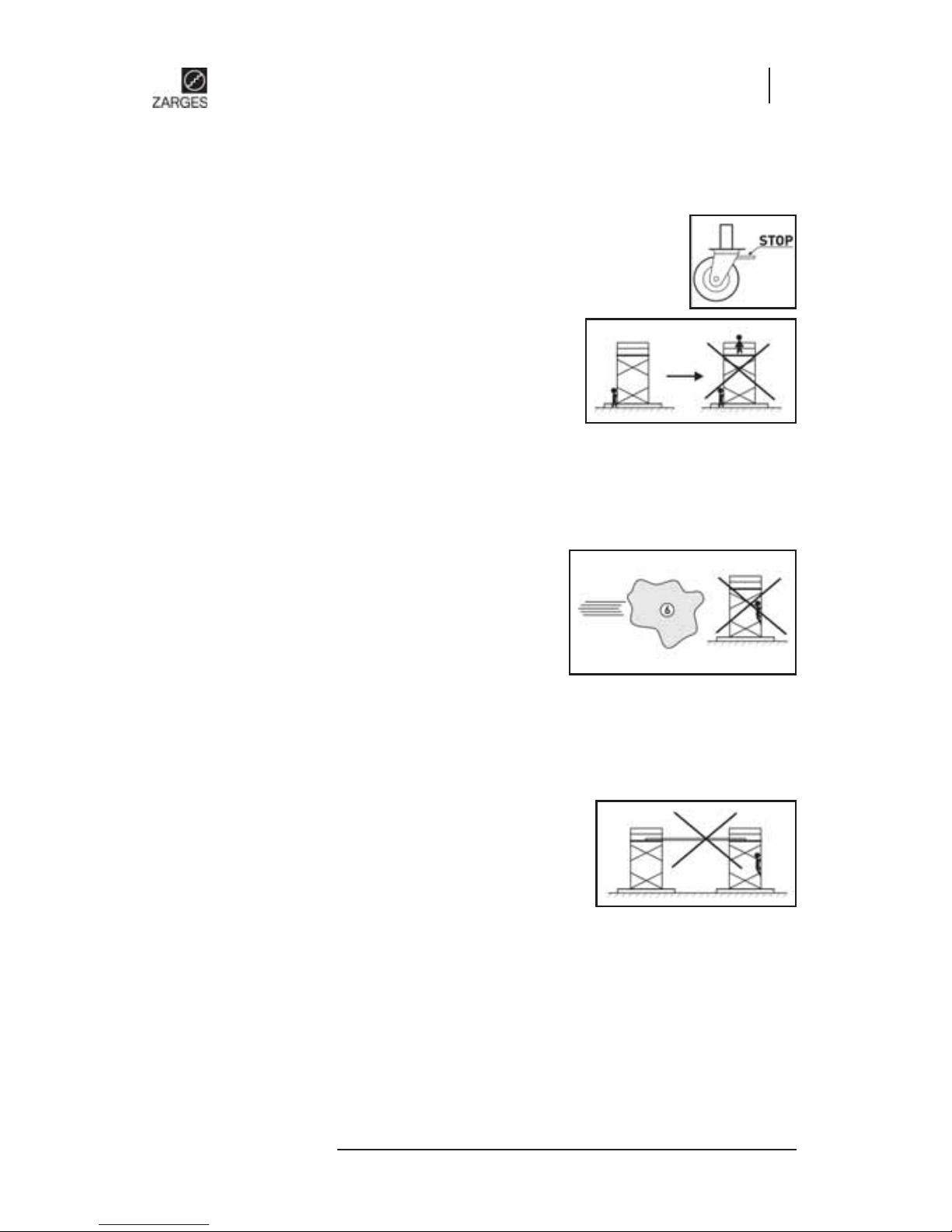
15. All swivel castors must be fi xed by pressing down the brake lever.
The brake lever may only be released for moving.
16. When moving the scaffold, neither people nor material
or tools may be on the platform. Avoid all collisions.
Move the scaffold only by hand in the lengthwise or
diagonal direction on solid, level and obstacle-free
surfaces. When moving, normal walking speed may
not be exceeded.
17. Moving the scaffold with the assistance of vehicles (e.g. fork lifts) is forbidden.
The scaffold may not be lifted or pulled or pushed with the fork lift.
18. The area on which the scaffold is moved must be able to accommodate its weight.
19. For use outdoors or in open buildings, the scaffold
must be moved into a wind-protected area if
there are wind strengths above 6 (according
to the Beaufort scale), in case of an oncoming
storm and when work is complete and protected
against tipping with other suitable measures
(e.g. anchoring). The exceeding of the wind
strength 6 (12 m/s) can be detected with a palpable drag when walking.
20. With the use of anchors in connection with anchor fi tting connections, the information
in the "Bulletin for the attachment of dowels to anchors of facade scaffolds" (can be
ordered from Carl Heymanns Verlag KG, Luxemburger Straße 449 in 50939 Cologneorder no. ZH 1/500) must be heeded.
21. The bridging of scaffolds to buildings with planks
is not permitted. The scaffold may not be used as a
stair tower in order to reach other constructions from
there.
22. Before using the scaffold, the vertical alignment of the scaffold must be checked and
corrected if neces sary . F urthermore, the scaff old must be checked to ensur e compl ete
assembly according to section 2.8.
23. With the use of stabilisers, these must always be attached under a frame. The antitwist devices of the stabilisers must always be attached.
Z200-300-AA-RC4_EN.indd 7Z200-300-AA-RC4_EN.indd 7 28.02.2008 10:20:4728.02.2008 10:20:47
Page 8

Operating and assembly instructions
Z200 / Z300
8
2.2. Behaviour for work on electrical systems with the scaffold
Work on or in the proximity of unprotected live systems, may not be carried out using
the scaffold if
• the system component is not disconnected,
• the system component is not secured against switching on,
• if there is voltage in the system component,
• the system component is not short-circuited with an earthing rail,
• the system component is not isolated against adjacent live parts.
2.3. Further applicable safety instructions
For the inspection, assembly and usage of the scaffold, the following provisions are applicable:
• BGI 663 " Instructions for action for handling work and protective scaffolds"
For the use of electrical de vices on the scaffold, the pr ovisions of BGR 165 and BGI 594 (pre viously
ZH 1/228) "Safety rules for the use of electrical equipment with increased electrical hazard"
apply.
2.4. Technical specifi cations
Z200 folding scaffold 0.7 m × 1.5 m
Approved according to EN 1004 Scaffold group 3
Permissible load according to scaffold group 3 200 kg/m²
Total load of the scaffold (maximum) 210 kg
Load of the platform (maximum) 210 kg
Maximum platform height 6.60 m
Z200 mobile scaffold tower 0.7 m × 1.5 m
Approved according to EN 1004 Scaffold group 3
Permissible load according to scaffold group 3 200 kg/m²
Total load of the scaffold (maximum) 210 kg
Load of the platform (maximum) 210 kg
Maximum platform height 6.85 m
Z300 folding scaffold 0.7 m × 2.0 m
Approved according to EN 1004 Scaffold group 3
Permissible load according to scaffold group 3 200 kg/m²
Total load of the scaffold (maximum) 280 kg
Load of the platform (maximum) 280 kg
Maximum platform height 9.60 m
Z300 mobile scaffold tower 0.7 m × 2.0 m
Approved according to EN 1004 Scaffold group 3
Permissible load according to scaffold group 3 200 kg/m²
Total load of the scaffold (maximum) 280 kg
Load of the platform (maximum) 280 kg
Maximum platform height 9.85 m
Z200-300-AA-RC4_EN.indd 8Z200-300-AA-RC4_EN.indd 8 28.02.2008 10:20:4728.02.2008 10:20:47
Page 9
Operating and assembly instructions
Z200 / Z300
9
Z200 / Z300
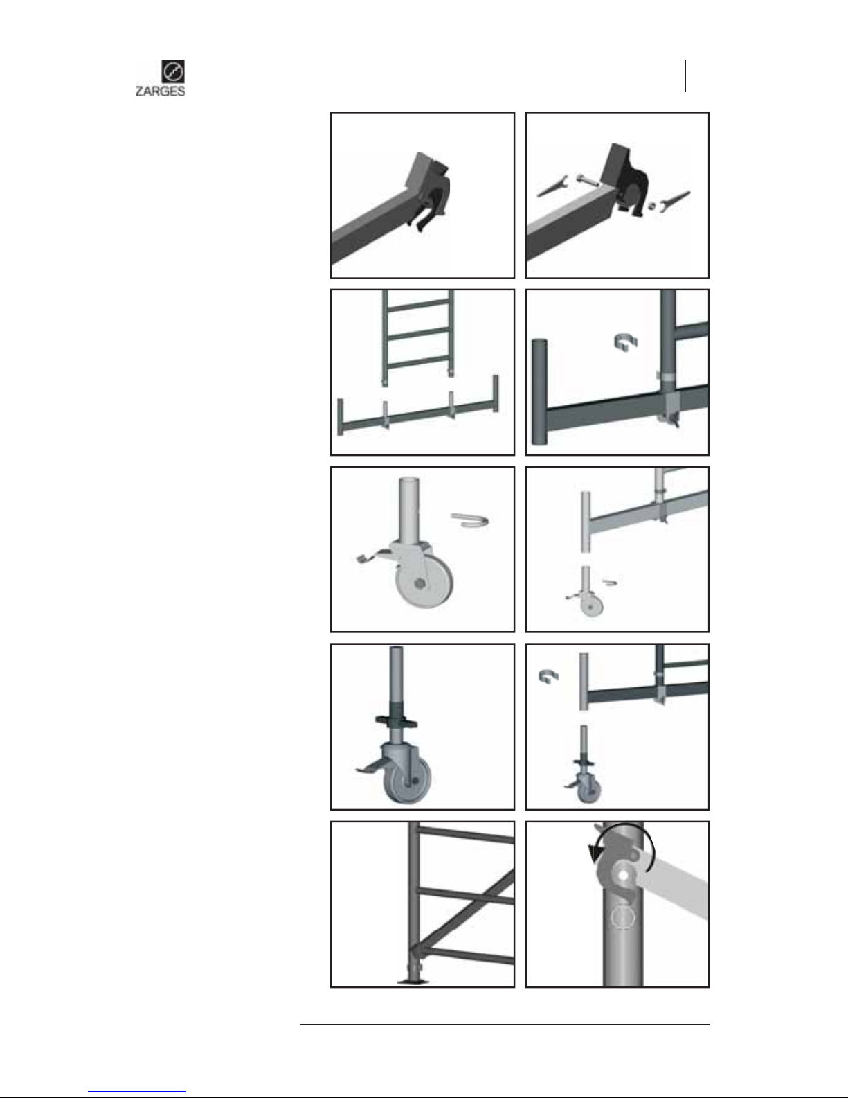
2. Assembly of slip-in frame
on chassis beams
Fig. 3. Fig. 4.
3. Assembly of swivel castor s,
with pivots on the chassis
beams
(base plates are included in the
basic package)
Fig. 5. Fig. 6.
4. Assembly of swivel castor s,
with shafts on the chassis
beams
(base plates are included in the
basic package)
Fig. 7. Fig. 8.
5. Assembly of diagonal
braces
The fi rst diagonals always be-
gin on the 1st rung from the
bottom!!! After that, the diagonals run zig-zag up the long
side of the scaffold.
Fig. 9. Fig. 10.
Ð
Ð
Ô
Î
Í
Ï
1.
2.
Ô
1.
2.
Ï
Ð
2.5. General design specifi ca-
tions
1. Preparatory work for
assembly
Fig. 1. Fig. 2.
1.
2.
Ô
Page 10
Operating and assembly instructions
Z200 / Z300
10
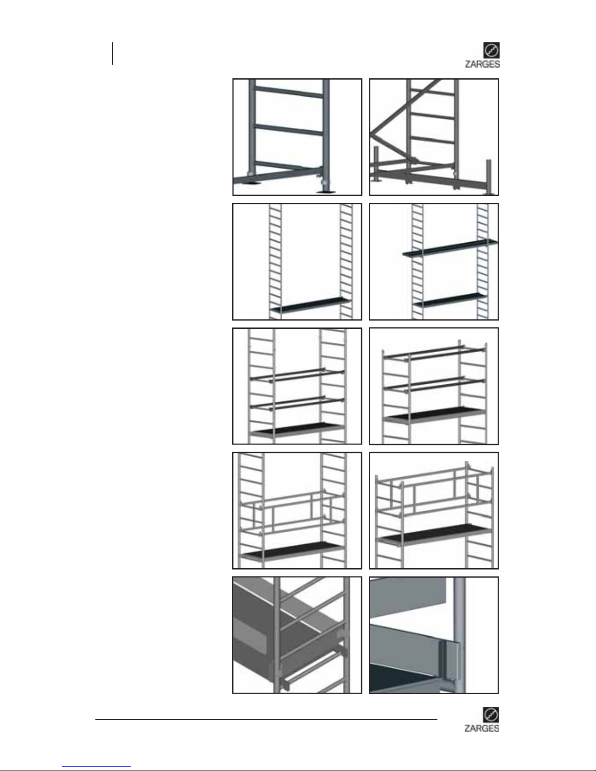
7. Assembly of platform
Scaffold planks or platforms
must be installed as assembly
aids. The platform serves as a
place to stand for the further
assembly (cf. section 2.1 no. 7).
After the scaffold is complete,
all assembly aids (scaffold
planks, etc.) must be removed.
Fig. 13. Fig. 14.
ÐÐ
1. 2.
3.
max.
0.5m
Ò
Fig. 19. Fig. 20.
10. Assembly of toe boards
(lengthwise board, crosswise
board)
1.
2.
Ô
Ð
Ð
8.1 Assembly of railings Z200
For Fig. 15:
Railings for intermediate
platform
For Fig. 16:
Railings for working platform
(uppermost platform)
Fig. 15. Fig. 16.
Ï
Ð
Ô
Ô
8.2 Assembly of railings Z300
For Fig. 17:
Railings for intermediate
platform
For Fig. 18:
Railings for working platform
(uppermost platform)
Fig. 17. Fig. 18.
Ï
Ð
Ô
Ô
6. Assembly of diagonal
braces
Fig. 11.
Ð
Ð
Ð
Fig. 12.
Z200-300-AA-RC4_EN.indd 10Z200-300-AA-RC4_EN.indd 10 28.02.2008 10:20:5428.02.2008 10:20:54
Page 11
Operating and assembly instructions
Z200 / Z300
11
Z200 / Z300
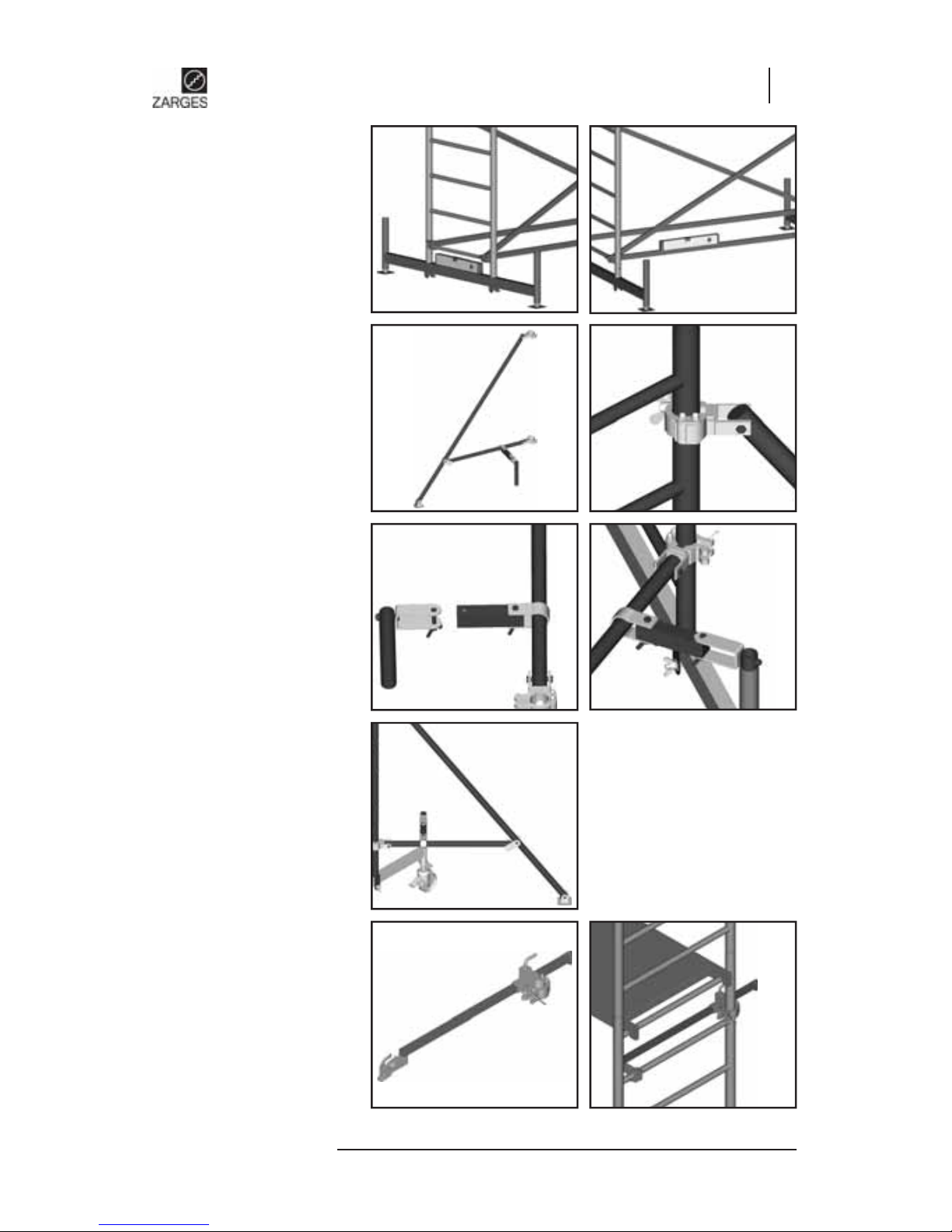
12. Assembly of stabilisers
Only for mobile scaffold towers with stabilisers (D and E
module).
Fig. 23. Fig. 24.
Fig. 25. Fig. 26.
1.
2.
Ñ
Ô
11. Aligning the scaffold
After the scaffold has been assembled, it must be aligned using a spirit level. If the scaffold
should be moved to its usage
location only after assembly,
its alignment must absolutely
be checked again on location.
Fig. 21.
Fig. 22.
13. Assembly of wall anchor
Fig. 28. Fig. 29.
3.
4.
Fig. 27.
Z200-300-AA-RC4_EN.indd 11Z200-300-AA-RC4_EN.indd 11 28.02.2008 10:20:5728.02.2008 10:20:57
Page 12
Operating and assembly instructions
Z200 / Z300
12
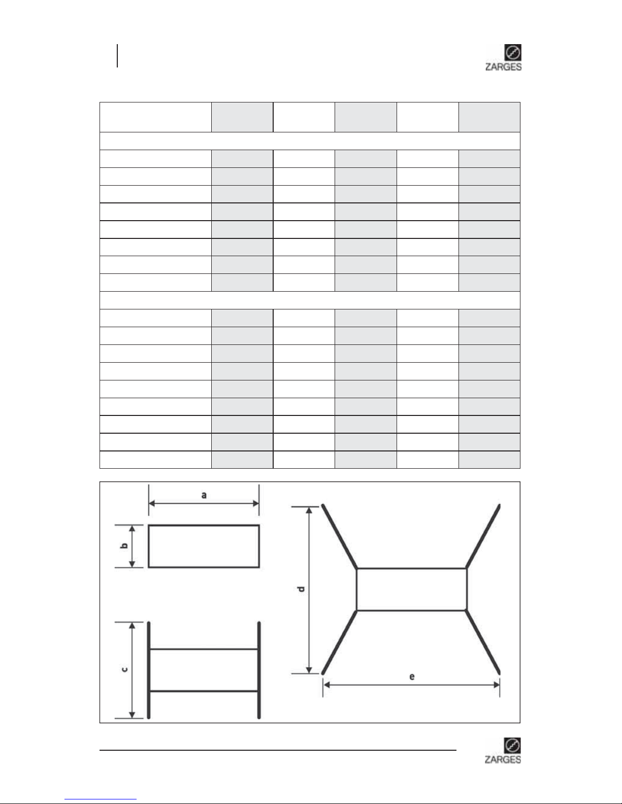
2.6. Basic measurements
Module / dimensions
[mm]
abcde
Z200 0.7 m × 1.5 m
A
1500 700 - - -
A+B
1500 700 1500 - -
A+B+C
1500 700 1500 - -
A+B+C+D
1500 700 1500 3000 2800
K
1500 700 - - -
K+B
1500 700 1500 - -
K+B+C
1500 700 1500 - -
K+B+C+D
1500 700 1500 3000 2800
Z300 0.7 m × 2.0 m
A
2000 700 - - -
A+B
2000 700 1650 - -
A+B+C
2000 700 1650 - -
A+B+C+D
2000 700 1650 3000 3300
A+B+C+D+E
2000 700 1650 3000 3300
K
2000 700 - - -
K+B
2000 700 1650 - -
K+B+C
2000 700 1650 - -
K+B+C+D
2000 700 1650 3000 3300
Z200-300-AA-RC4_EN.indd 12Z200-300-AA-RC4_EN.indd 12 28.02.2008 10:20:5828.02.2008 10:20:58
Page 13
Operating and assembly instructions
Z200 / Z300
13
Z200 / Z300
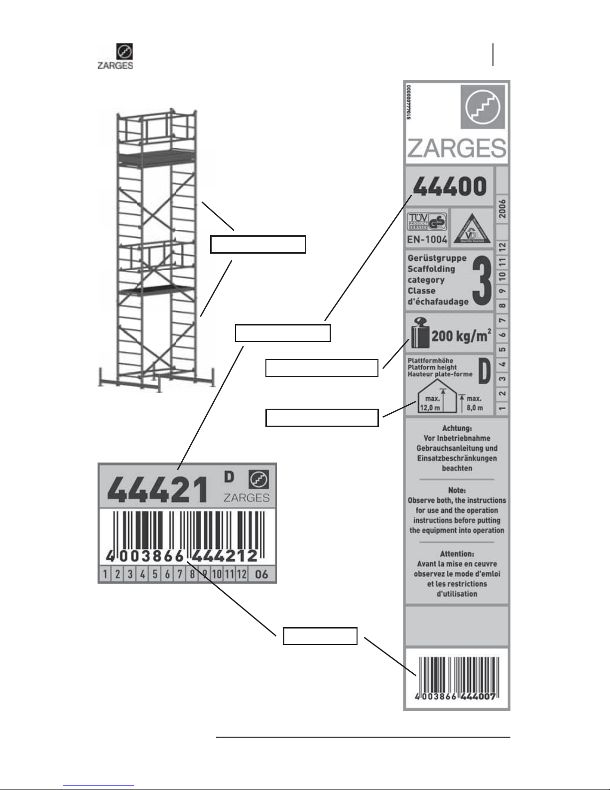
2.7. Identifi cation
Item no.
Type plate
Max. platform height
Load max.
EAN code
Z200-300-AA-RC4_EN.indd 13Z200-300-AA-RC4_EN.indd 13 28.02.2008 10:20:5928.02.2008 10:20:59
Page 14

Operating and assembly instructions
Z200 / Z300
14
2.8. Parts list incl. ballasting (see also 5.2)
The parts list includes the designation of the individual parts, their associated weights, the item
no. of the individual parts which are included in the complete scaffold and the item no. of the
complete scaffold. The necessary ballasting per scaffold is also listed.
Z200 / Z300 mobile scaffold towers
Scaffold size
Working height
1)
Parts list
Basic frame 1.75 m
Folding unit
Slip-in frame 1 m
Slip-in frame 2 m
Railings 2)Platform with fl ap
Crosswise board
Lengthwise board
Diagonal brace
Horizontal brace
Chassis beams
3)
Stabilisers
Base plates
Ballasting
Interior
usage
Outdoor
usage
centre erection
side erection
2)
centre erection
side erection
2)
approx. [m]
Order
no.
44400
44468
44407
44405-44435
44445
44440
44420
44410
44450
44455
44459
Z200 0.7 × 1.5
2.55 48409
-1-- 1---1--4
Number of ballast weights over each swivel cas-
tor
0000
2.80 48400
2--- 1--11--4 0000
5.00 48401
--21 -22252-- 33/333/3
7.00 48402
---2 1--34--- 57/757/7
9.00 48403
---2 ---2--4- 22/222/2
approx. [m]
Order
no.
44400
44404
44407
44405
44413
44436
44445
44441
44421
44411
44451
44455
44459
44460
4)
Z300 0.7 × 2.0
2.55 44509
-1---1---1--4 0000
2.80 44500
2----1--11--4 0000
5.00 44501
--212-22212-- 11/211/2
7.00 44502
---221--3---- 33/543/5
9.00 44503
---2----2--4- 00/020/0
12.00 44504
---321--2---- 22/222/2
1)
With footplates; when swivel castors 44 454 are used = 22 cm to max. 33 cm; 44 453 = +16 cm (at an extr a cost). Ballast w eights
not included in the scope of delivery.
2)
Is replaced with 2 horizontal braces.
3)
Length of the chassis beams for the Z300: 1.65 m of galvanised steel; for the Z200: 1.50 m of aluminium.
4)
In the case of side erection, sometimes more ballast weights are located on the side facing away from the wall.
(Example: 3/5 = 3 weights on the side facing the wall and 5 ballast weights on the side facing away from the wall)
With more than 4 ballast weights per swivel castor, additional slip-in pipes (44449) must be used.
Pay attention to the ballasting specifi cations in the operating and assembly instructions!
Z200-300-AA-RC4_EN.indd 14Z200-300-AA-RC4_EN.indd 14 28.02.2008 10:21:0128.02.2008 10:21:01
Page 15

Operating and assembly instructions
Z200 / Z300
15
Z200 / Z300
2.9. Position of the individual parts
Slip-in frame 2.00 m
Slip-in frame 1.00 m
Folding unit
Platform with access way
Crosswise toe board
Lengthwise toe board
Diagonal brace
Horizontal brace
Stabilisers
Chassis beams
Railings
Z200-300-AA-RC4_EN.indd 15Z200-300-AA-RC4_EN.indd 15 28.02.2008 10:21:0228.02.2008 10:21:02
Page 16

16
Operating and assembly instructions
Z200 / Z300
Scaffold comb.
Module
A
Working height
approx. 2.90 m
Scaffold height
1.75 m
Platform
height
0.90 m
Weight
23.1 kg
Order no.
48400
Scaffold comb.
Module
A+B
Working height
approx. 4.85 m
Scaffold height
3.95 m
Platform
height
2.85 m
Weight
83.1 kg
Order no.
48540
Scaffold comb.
Module
A+B+C
Working height
approx. 6.85 m
Scaffold height
5.95 m
Platform
height
4.85m
Weight
111.2 kg
Order no.
48541
Scaffold comb.
Module
A+B+C+D
Working height
approx. 8.85 m
Scaffold height
7.95 m
Platform
height
6.85 m
Weight
152.2 kg
Order no.
48542
2.10. Assembly drawings
Z200 Mobile scaffold tower, 0.7 m × 1.5 m
Z200-300-AA-RC4_EN.indd 16Z200-300-AA-RC4_EN.indd 16 28.02.2008 10:21:0428.02.2008 10:21:04
Page 17

Z200 / Z300
17
Operating and assembly instructions
Z200 / Z300
Scaffold comb.
Module
K
Working height
approx. 2.70 m
Scaffold height
1.50 m
Platform
height
0.70 m
Weight
24.9 kg
Order no.
48409
Scaffold comb.
Module
K+B
Working height
approx. 4.60 m
Scaffold height
3.70 m
Platform
height
2.60 m
Weight
84.9 kg
Order no.
48590
Scaffold comb.
Module
K+B+C
Working height
approx. 6.60 m
Scaffold height
5.70 m
Platform
height
4.60 m
Weight
113.0 kg
Order no.
48591
Scaffold comb.
Module
K+B+C+D
Working height
approx. 8.60 m
Scaffold height
7.70 m
Platform
height
6.60 m
Weight
154.0 kg
Order no.
48592
Z200 Folding scaffold, 0.7 × 1.5
Z200-300-AA-RC4_EN.indd 17Z200-300-AA-RC4_EN.indd 17 28.02.2008 10:21:1528.02.2008 10:21:15
Page 18

18
Operating and assembly instructions
Z200 / Z300
Scaffold comb.
Module
A+B+C+D
Working
height
approx. 8.85 m
Scaffold
height
7.95 m
Platform
height
6.85 m
Weight
156.1 kg
Order no.
44542
Scaffold comb.
Module
A+B+C+D+E
Working
height
approx. 11.85
m
Scaffold
height
10.95 m
Platform
height
9.85 m
Weight
197.7 kg
Order no.
44543
Z300 Mobile scaffold tower, 0.7 × 2.0
Scaffold comb. Platform height
Module
A
0.90 m
Working height Weight
approx. 2.90 m 27.1 kg
Scaffold height Order no.
1.75 m 44500
Scaffold comb. Platform height
Module
A+B
2.85 m
Working height Weight
approx. 4.85 m 79.6 kg
Scaffold height Order no.
3.95 m 44540
Scaffold comb. Platform height
Module
A+B+C
4.85m
Working height Weight
approx. 6.85 m 114.3 kg
Scaffold height Order no.
5.95 m 44541
Z200-300-AA-RC4_EN.indd 18Z200-300-AA-RC4_EN.indd 18 28.02.2008 10:21:2628.02.2008 10:21:26
Page 19

Z200 / Z300
19
Operating and assembly instructions
Z200 / Z300
Z300 Folding scaffold, 0.7 × 2.0
Scaffold comb.
Module
A+B+C+D
Working
height
approx. 8.60 m
Scaffold
height
7.70 m
Platform
height
6.60 m
Weight
160.1 kg
Order no.
44592
Scaffold comb.
Module
A+B+C+D+E
Working
height
approx. 11.60
m
Scaffold
height
10.70 m
Platform
height
9.60 m
Weight
201.7 kg
Order no.
44593
Scaffold comb. Platform height
Module
A
0.70 m
Working height Weight
approx. 2.70 m 31.1 kg
Scaffold height Order no.
1.50 m 44509
Scaffold comb. Platform height
Module
A+B
2.60 m
Working height Weight
approx. 4.60 m 83.6 kg
Scaffold height Order no.
3.70 m 44590
Scaffold comb. Platform height
Module
A+B+C
4.60 m
Working height Weight
approx. 6.60 m 118.3 kg
Scaffold height Order no.
5.70 m 44591
Z200-300-AA-RC4_EN.indd 19Z200-300-AA-RC4_EN.indd 19 28.02.2008 10:21:3828.02.2008 10:21:38
Page 20

Operating and assembly instructions
Z200 / Z300
20
3. Note about disassembly of the scaffold
Disassembly of the erected scaffold occurs in the reverse order of assembly. Here it must be
noted that the platforms or scaffold planks necessary for the assembly personnel must be
laid out in advance as places to stand and thereby laid out completely. In no case may parts of
the scaffold (braces, platforms, etc.) be disassembled before the levels above them have been
disassembled completely.
4. Usage rules and regulations
1. Ascent to the working platform may only occur from the
inside.
2. It is not permitted to lean against the side protector while
working.
3. It is not permitted to jump on the panel coverings.
4. No horizontal loads may be generated, e.g. due to work on adjacent
constructions which could cause the scaffold to tip.
5. While using scaffolds in passageway buildings, on uncovered buildings or building corners,
special attention must be paid to the wind situation in order to prevent the scaffold from
tipping over.
6. It is forbidden to extend the platform height by using ladders, crates or other equipment.
7. Tools and materials may onl y be handed upwards. Her e, the w eight of the tools and materials
must always be taken into acc ount in order not to overload the w orking platf orm. The per son
lifting the load may only l et go when the person acc epting the load has it secur el y in his or her
hands.
8. Scaffolds with swivel castors can be moved to their later location after assembly (fl oor slant
may not be more than 3%). Avoid all collisions. After moving, the alignment of the scaffold
must be checked again.
9. When moving the scaffold, always pay attention that no live system components are
touched.
10. Electrical devices (drills, etc.) may only be operated on the scaffold with protection low
voltage (48 V), with protective isolation (separation transformer) or if they are connected to a
residual current oper ated devic e with a r esidual current of 30 mA. The regulations of BGI 594
(previously ZH 1/228) must be applied.
11. Tools and materials must be stored on the working platform so that 20 cm on the side of
the working platform remains free as a passageway.
Z200-300-AA-RC4_EN.indd 20Z200-300-AA-RC4_EN.indd 20 28.02.2008 10:21:5028.02.2008 10:21:50
Page 21

Operating and assembly instructions
Z200 / Z300
21
Z200 / Z300
Extension pipe
Order no.: 44449
Ballast weights
Order no.: 44460
5.3. Maintenance, repair, storage and cleaning
Clean the scaffold with water and commercial cleansers. If paint gets on the scaffold, it can be
removed with turpentine. Cl eansers may not penetrate the soil; used cleanser s must be disposed
of in accordance with the applicable environmental regulations.
Greasing the moving parts
Grease all moving parts (spindle, swivel castor bearing, catches) with commercial oil. For use
in the winter, use low viscosity oil. Wipe off excess oil, the oil may not reach the treads - danger
of slipping. Dispose of cleaning rags soiled with grease in accordance with the applicable
environmental regulations.
Storage
Storage must be in a manner such that damage to the unit is excluded. The scaffold c omponents
must be stored so that they are protected against the effects of weather. During transport to
or from the storage location, the scaffold components must be secured against slipping and
bumping as well as falling down. When loading, the scaffold components may not be thrown.
5. Stability specifi cations
5.1. General information
Chassis beams and stabilisers are responsible for the stability of the scaffold. However, these
must also be ballasted according to the area of deployment (indoors / outdoors). For the correct
ballasting, please see the parts lists (packet 2.8).
5.2. Fastening the ballasting
The attachment location and the quantity of the ballast weights depend on the type of assembly
and platform height of the scaffold. For the pr ecise quantity of the ballasting, pl ease see the parts
lists in section 2.8 (lower portion of the tables).
Attach ballast weights over the supports on the swivel castors, see Fig. below. For scaffolds for
which a larger number of ballast weights are required, the supports on the chassis beams can
be lengthened with slip-in pipes (accessory, order no. 44449).
Z200-300-AA-RC4_EN.indd 21Z200-300-AA-RC4_EN.indd 21 28.02.2008 10:21:5128.02.2008 10:21:51
Page 22

Operating and assembly instructions
Z200 / Z300
22
5.4. Inspections of the scaffold components
If a defect is discovered, the affected part may not be used any longer.
Slip-in frame / chassis beams
• Check for deformation, crushing and crack formation.
Braces (diagonal / railings)
• Check for deformation, crushing, crack formation and function of the catches.
Platform
• Check for deformation, crushing, crack formation and function of the catches.
• Check state of the wood.
• Check pass-through fl ap for function.
Toe boards
• Check state of the wood.
• Check toe boards for crack formation.
Swivel castors
• Check rolling capacity of the castor and function of the brake on rolling and
basic frame.
• For swivel castors with spindle, also check that spindle can move freely.
• Check fail safe (thumb screw, plug) on the chassis beams and and basic frame.
Safety springs
• Check for deformation, crushing, crack formation and tight fi t.
If you would like information or if you have special
problems that are not treated in suffi cient detail in these
operating and assembly instructions, you can request
the required information directly from the manufacturer
(see section 1.2).
Furthermore, we hereby notify you that the content of
these operating and assembly instructions is not part of an
earlier existing agreement, covenant or a legal relationship
nor should it change these. All obligations arise from
the respective purchase contract, which also contains
the complete and solely-valid warranty regulation (see also
section 1.4). These contractual warranty regulations are
neither extended nor limited by the details of these operating
and assembly instructions.
The propagation and duplication of these documents,
the exploitation and communication of their content are only
permissible with the expr ess permission of the manufacturer .
Violations which contradict the details above are subject to
punitive damages.
Z200-300-AA-RC4_EN.indd 22Z200-300-AA-RC4_EN.indd 22 28.02.2008 10:21:5128.02.2008 10:21:51
Page 23

Operating and assembly instructions
Z200 / Z300
23
Z200 / Z300
6. Spare parts
Platform with fl ap
1.5 m 44435
2.0 m 44436
Railings Z300
2.0 m 44413
Folding unit
1.5 m 44468
2.0 m 44404
Slip-in frame
1.0 m 44407
2.0 m 44405
Basic frame
1.75 m 44400
Z200-300-AA-RC4_EN.indd 23Z200-300-AA-RC4_EN.indd 23 28.02.2008 10:21:5228.02.2008 10:21:52
Page 24

Operating and assembly instructions
Z200 / Z300
24
Crosswise board
0.70 m 44445
Lengthwise board
1.5 m 44440
2.0 m 44441
Diagonal brace
1.5 m 44420
2.0 m 44421
Horizontal brace
1.5 m 44410
2.0 m 44411
Chassis beams
1.50 m (alu) 44450
1.65 m (steel) 44451
Z200-300-AA-RC4_EN.indd 24Z200-300-AA-RC4_EN.indd 24 28.02.2008 10:21:5228.02.2008 10:21:52
Page 25
Operating and assembly instructions
Z200 / Z300
25
Z200 / Z300
Stabilisers
2.2 m 44455
Base plates
0.30 m 44459
Z200-300-AA-RC4_EN.indd 25Z200-300-AA-RC4_EN.indd 25 28.02.2008 10:21:5328.02.2008 10:21:53
Page 26
Operating and assembly instructions
Z200 / Z300
26
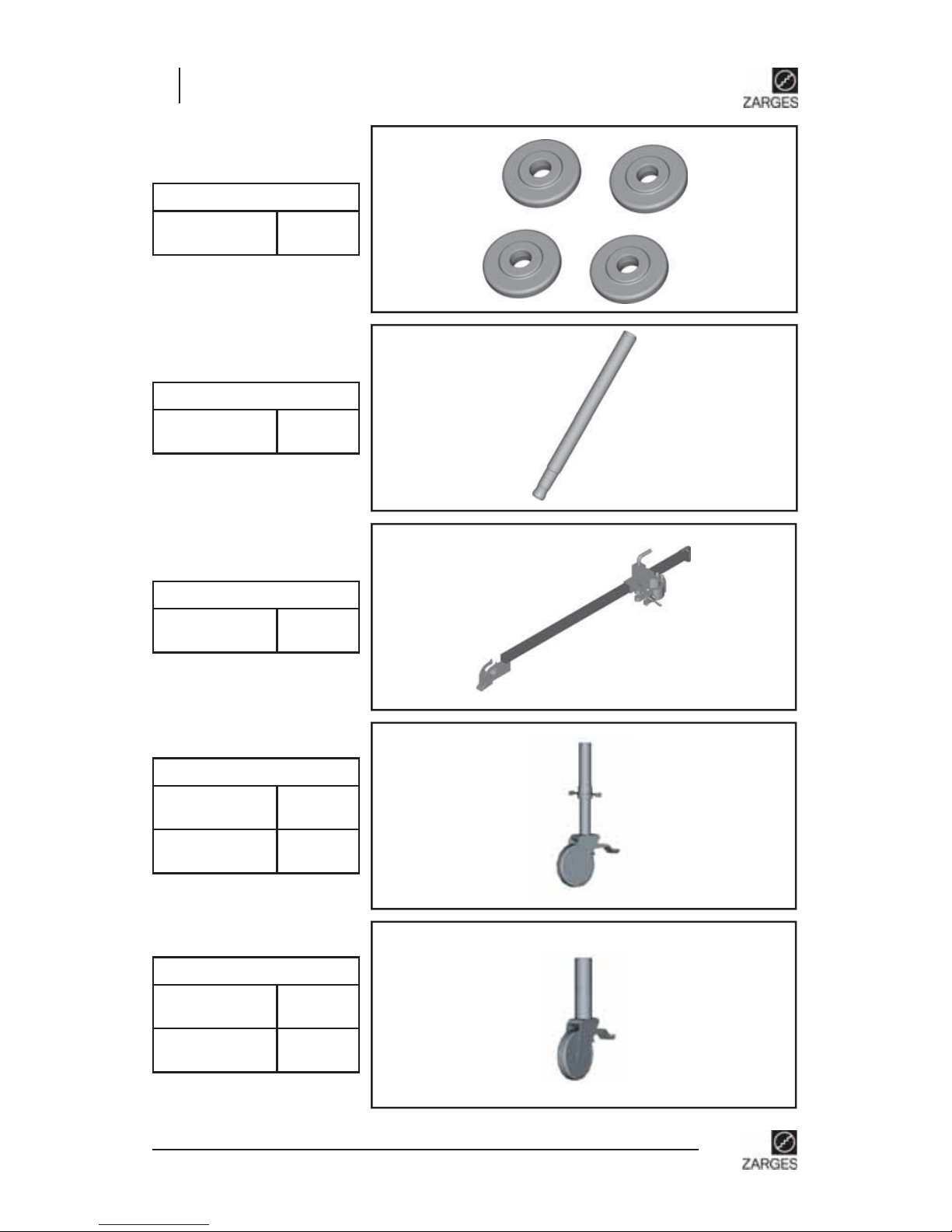
7. Accessories
Ballast weight (disk)
10.0 kg 44460
Swivel castors 150 mm
No. pieces 44454
VE (4 pcs.) 44444
Slip-in pipe of alu
0.6 m 44449
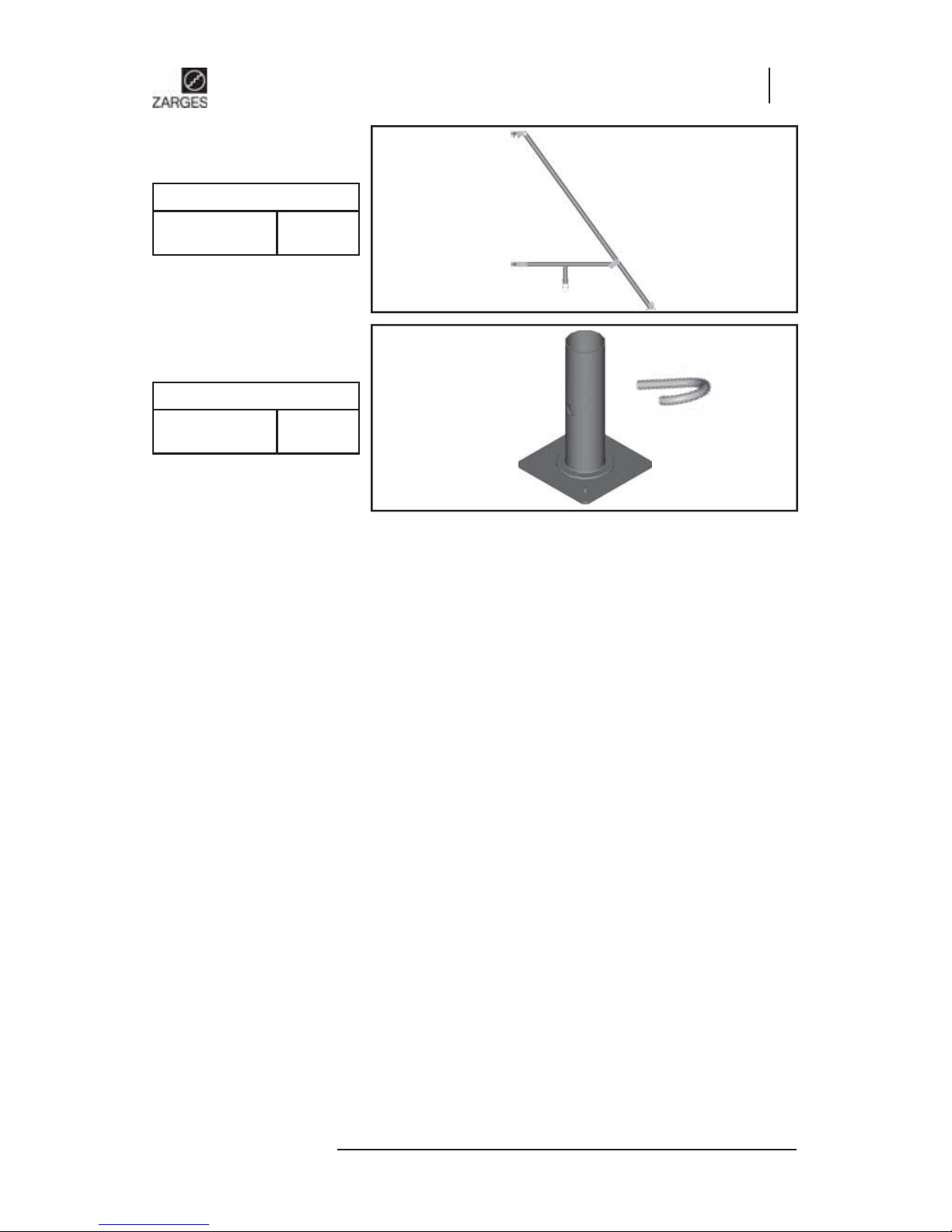
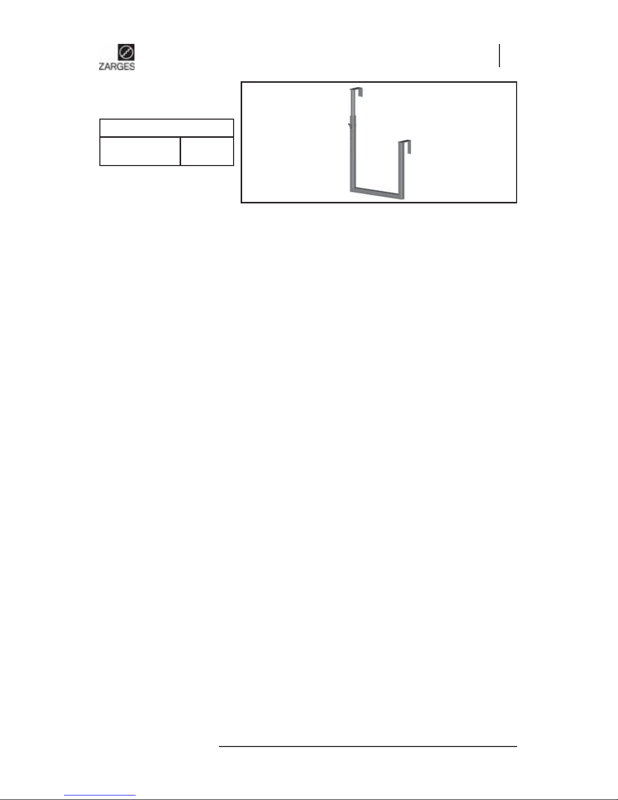
Wall anchor
1.0 m 44461
Swivel castors 125 mm
No. pieces 44453
VE (4 pcs.) 44433
Z200-300-AA-RC4_EN.indd 26Z200-300-AA-RC4_EN.indd 26 28.02.2008 10:21:5328.02.2008 10:21:53
Page 27
Operating and assembly instructions
Z200 / Z300
27
Z200 / Z300
Entry arm (steel)
0.3 m 44456
Z200-300-AA-RC4_EN.indd 27Z200-300-AA-RC4_EN.indd 27 28.02.2008 10:21:5428.02.2008 10:21:54
Page 28

Operating and assembly instructions
Z200 / Z300
28
NOTES
Z200-300-AA-RC4_EN.indd 28Z200-300-AA-RC4_EN.indd 28 28.02.2008 10:21:5428.02.2008 10:21:54
Page 29

Operating and assembly instructions
Z200 / Z300
29
Z200 / Z300
NOTES
Z200-300-AA-RC4_EN.indd 29Z200-300-AA-RC4_EN.indd 29 28.02.2008 10:21:5528.02.2008 10:21:55
Page 30

Operating and assembly instructions
Z200 / Z300
30
NOTES
Z200-300-AA-RC4_EN.indd 30Z200-300-AA-RC4_EN.indd 30 28.02.2008 10:21:5528.02.2008 10:21:55
Page 31

Operating and assembly instructions
Z200 / Z300
31
Z200 / Z300
NOTES
Z200-300-AA-RC4_EN.indd 31Z200-300-AA-RC4_EN.indd 31 28.02.2008 10:21:5528.02.2008 10:21:55
Page 32

Operating and assembly instructions
Z200 / Z300
32
NOTES
Z200-300-AA-RC4_EN.indd 32Z200-300-AA-RC4_EN.indd 32 28.02.2008 10:21:5528.02.2008 10:21:55
Page 33

Operating and assembly instructions
Z200 / Z300
33
Z200 / Z300
NOTES
Z200-300-AA-RC4_EN.indd 33Z200-300-AA-RC4_EN.indd 33 28.02.2008 10:21:5628.02.2008 10:21:56
Page 34

Operating and assembly instructions
Z200 / Z300
34
NOTES
Z200-300-AA-RC4_EN.indd 34Z200-300-AA-RC4_EN.indd 34 28.02.2008 10:21:5628.02.2008 10:21:56
Page 35

Z200-300-AA-RC4_EN.indd 35Z200-300-AA-RC4_EN.indd 35 28.02.2008 10:21:5628.02.2008 10:21:56
Page 36

No291291 EN
N
o
540291291000
Z200-300-AA-RC4_EN.indd 36Z200-300-AA-RC4_EN.indd 36 28.02.2008 10:21:5628.02.2008 10:21:56
 Loading...