

Zareba G550 Installation Manual
SMART SYSTEMS FOR ACCESS CONTROL
AUTOMATIC GATE OPENER
INSTALLATION MANUAL
Part #7001623.001 Rev. 2
Model G550
For Single Gates

G550 Automatic Gate Opener Installation Manual
GATE OPENER CLASS CATEGORIES*
The Zareba Automatic Gate Opener is intended for use with vehicular swing gates. The opener can be used in Class I,
Class II, Class III and Class IV applications.
Residential Vehicular Gate Opener–Class I: A vehicular gate opener (or system) intended for use in a home of one-to-four
single family dwelling, or a garage or parking area associated therewith.
Commercial/General Access Vehicular Gate Opener–Class II: A vehicular gate opener (or system) intended for use in a
commercial location or building such as a multifamily housing unit (five or more single family units), hotel, garages,
retail store or other building servicing the general public.
Industrial/Limited Access Vehicular Gate Opener–Class III: A vehicular gate opener (or system) intended for use in an
industrial location or building such as a factory or loading dock area or other locations not intended to service the general public.
Restricted Access Vehicular Gate Opener–Class IV: A vehicular gate opener (or system) intended for use in a guarded
industrial location or building such as an airport security area or other restricted access locations not servicing the general public, in which unauthorized access is prevented via supervision by security personnel.
*Categories established by Underwriters Laboratories for vehicle gate operators (openers).
FOR YOUR RECORDS
Please record the serial number (found on the control box cover) and purchase information below. Keep this with your
proof of purchase (receipts) in case your product is lost, stolen or requires service.
Serial number: ________________________________________________________________________________
Purchase date: ________________________________________________________________________________
Retailer/store name: ____________________________________________________________________________
Location of purchase: City __________________________________________ State________________________
2

SMART SYSTEMS FOR ACCESS CONTROL
READ THIS FIRST
Warning: Before installing your Zareba Automatic Gate Opener (sometimes also referred to as the
“Product”), read this entire Installation Manual for information about Product safety matters and
proper use of the Product. Only use the Product for the purpose of a vehicular fence gate.
WARNING OF RISKS, PURCHASER’S RESPONSIBILITIES, AND
ASSUMPTION OF CERTAIN RISKS:
The directions for installation and use of the Product must be followed carefully. It is impossible to eliminate all risks
inherently associated with the use of the Product. The effectiveness of the Zareba Automatic Gate Opener depends
on proper installation and the manner of use or application, all of which are beyond the control of Zareba Systems
or the seller. All such risks are assumed by the purchaser by the purchaser’s installation and use of the Product.
The Zareba Automatic Gate Opener is for use on vehicular fence gates only. The Product meets or exceeds the
requirements of UL 325, the standard that regulates gate opener safety, as established and made effective March
14, 2003, by Underwriters Laboratories, Inc.
Zareba Systems
906 Fifth Avenue E
Ellendale, MN 56026-2193
Toll free: 800-272-9877
Phone: 507-684-3721 Fax: 507-684-3722
Email: info@zarebasystems.com
zarebasystems.com
3

G550 Automatic Gate Opener Installation Manual
Table of Contents
An Introduction to Automatic Gate Openers .......................... page 5
Important Safety Information
General Safety Information ............................................. page 6
Protection Against Entrapment .......................................... page 7
Warning Signs and Labels .............................................. page 8
Additional Safety Devices .............................................. page 9
Pre-Installation Information
Tools and Parts List .................................................. page 11
Kit Contents .......................................................page 12
Installed Gate Opener Overview ........................................page 13
Circuit Board Layout .................................................page 14
Technical Specifications .............................................. page 15
Important Gate Information ........................................... page 15
Installation
Overview ......................................................... page 16
Bracket Mounting ................................................... page 16
Installation of Gate Opener (Actuator) ................................... page 22
Installation of the Control Box ......................................... page 22
Power Connection Between Control Box and Opener (Actuator) ............... page 23
Push-to-Open Installation ............................................. page 26
Brick, Masonry or Rock Column Installation ............................... page 28
Control Box Setting
Control Board Settings ............................................... page 29
Setting the Transmitter Code .......................................... page 30
Setting the Gate’s Closed Limit Position .................................. page 31
Automatic Close Time Adjustment ...................................... page 31
Obstruction Sensitivity Set Up ......................................... page 32
Accessory Installation ................................................ page 33
Operation
Powering Information ................................................ page 34
Manual Operation of Gate ............................................ page 36
Theft Deterrence ................................................... page 36
Maintenance and Troubleshooting Guide ............................ page 37
Warranty and Repair Information .................................. page 39
Gate Opener Accessories ........................................... page 40
Gate Opener and Accessory Order Form ............................. page 41
4

SMART SYSTEMS FOR ACCESS CONTROL
AN INTRODUCTION TO
AUTOMATIC GATE
OPENERS
Thank you for purchasing the Zareba Automatic Gate
Opener.
Your Zareba Automatic Gate Opener is designed for
years of trouble free performance. It will provide you
with a comfortable, safe, hassle-free way to access your
property.
The Zareba Automatic Gate Opener is designed to work
on single or dual swing gates. Each individual gate can
be up to 18 feet long and weigh up to 850 pounds.
Your gate opener will work on a variety of gate types
such as iron, tubular, chain link, vinyl, etc. It is not recommended to use an automatic gate opener on a solid
fence due to wind resistance. Depending on the
strength of the wind and the obstruction sensing, your
gate may not operate properly.
Your Zareba Automatic Gate Opener is designed to provide for safe operation. One of the most important features of your gate opener is obstruction sensing. Your
gate opener includes an adjustment for setting the sensitivity of the obstruction performance. When there is an
obstruction that prevents the gate from opening or
closing, the gate will immediately stop and reverse
direction. If the obstruction is removed the gate may be
activated to continue its path from where it stopped. If
the obstruction is not removed, the gate opener will
sound an alarm and will not operate again until the
gate opener system is reset.
There are a number of accessories that can be installed
with your gate opener that maximize your benefit to
owning the system. The accessories include additional
transmitters, keypad, pin lock, solar panel, in-ground
vehicle sensor, and others. Please see the List of
Accessories at end of this manual.
You may obtain additional copies of this manual from
our web site at www.zarebasystems.com, or contact
Zareba Systems at: 906 5th Ave. E, Ellendale, MN
56026, 1-800-272-9877.
Your Zareba Automatic Gate Opener can be opened
and closed in a variety of ways. Primarily, you will use
your remote transmitter (included with your unit) to
open or close the gate. However, the gate can also be
opened with a hardwired button, an automatic vehicle
sensor, a keypad, or built-in vehicle transmitter systems.
These accessories are discussed later in this manual. The
gate can also be closed with the hardwired button or
keypad. In addition it can be closed automatically using
a time delay that is set in the control box.
5

G550 Automatic Gate Opener Installation Manual
IMPORTANT SAFETY
INFORMATION
General Safety Information
Vehicular gates are large heavy objects. Automatic gate
openers provide a convenient way to open and close
the gates. Since the gate system and its components
exert a high level of force to open and close the gate,
they can be dangerous, causing severe injuries and
death to you and others.
Your safety and the safety of others depend on the
owner and users of this system to read, understand, and
follow the information and instructions in this manual.
Save this safety information for future use.
Safety overview checklist
WARNING – To reduce the risk of injury or death:
• Use this operator only with single swing gates.
• READ AND FOLLOW ALL INSTRUCTIONS.
• Never let children operate or play with gate controls.
Keep the remote control away from children.
• Always keep people and objects away from the gate.
NO ONE SHOULD CROSS THE PATH OF THE MOVING
GATE.
• Test the gate operator monthly. The gate MUST
reverse on contact with a rigid object or stop when an
object activates the non-contact sensors. After adjusting the force or the limit of travel, retest the gate
operator. Failure to adjust and retest the gate operator
properly can increase the risk of injury or death.
• KEEP GATES PROPERLY MAINTAINED. Read the owner’s manual. Have a qualified service person make
repairs to gate hardware if needed.
• The operator is intended for installation only on gates
used for vehicles. Pedestrians must be supplied with a
separate access opening. The pedestrian access opening shall be designed to promote pedestrian usage.
Locate the gate such that persons will not come in
conatct with the vehicular gate during the entire path
of travel of the vehicular gate.
• SAVE THESE INSTRUCTIONS
• Remember that the Zareba Automatic Gate Opener
must only be installed on gate systems meeting the
requirements of the application.
• Ensure that you are using the correct opener for the
type and size of gate, its frequency of use and the
class rating.
• Ensure that the gate and gate opener installation comply with applicable local codes.
• Contact local fire and law enforcement to arrange
emergency access procedures.
• Keep people, animals, and property away from the
gate area. Do not let children play in or near the gate
area.
• Use caution with moving parts to avoid injuring fingers or hands.
• Consider installing contact sensors, or non-contact
sensors to provide additional safety and protection
against entrapment.
• Never activate your gate opener until you ensure that
the area is clear of people, pets, or other obstructions.
Watch the gate until it stops.
• Do not drive forward until the gate stops completely.
6

SMART SYSTEMS FOR ACCESS CONTROL
Protection Against
Entrapment (fig. 1 and 2)
Figure 1
Important! Study Figures 1 and 2, and
keep safety foremost at all times.
Entrapment areas for a proper
pull-to-open installation
Entrapment Area 1
Hinged edge of the gate and the fence
post
Entrapment Area 2
Between the gate and the gate post
Entrapment Area 3
The path of the gate
Entrapment Area 4
The space between the gate in the
open position and any object such as
a wall, fence, tree, etc.
Entrapment Area 5
Pinch points between the opener and
gate or post
Area 1
fence
Area 5
Area 4
gate in open position
Area 2
fence
Area 3
driveway
Figure 2
fence
10’
10’
fence
10’
Moving Area of Gate
Never install any control device (such as a Push
Button) within 10’ of any moving gate part
10’
7
G550 Automatic Gate Opener Installation Manual
Protection Against Entrapment
The Zareba Automatic Gate Opener is designed to comply with UL 325, the safety standard covering automatic
gate opening systems. UL 325 requires that gate opening sytems shall have an inherent entrapment sensing
system and shall have the provisions for, or be supplied
with, at least one independent secondary means to protect against entrapment. The primary means of entrapment protection in the Zareba Automatic Gate Opener
is Type A, an inherent means of entrapment protection.
The secondary means of entrapment protection in the
Zareba Automatic Gate Opener is Type B2, the provision for the connection of a contact sensor (edge
sensor).
The gate opener’s built-in means of entrapment protection (Type A) may not be sensitive enough to prevent
bodily injury in some circumstances. Secondary means
of entrapment protection (Type B2), such as contact
(safety edge) sensors are suggested for enhanced safety.
See page 9 for important information on additional
safety devices.
Entrapment Alarm
(UL 325; 30.1)
In compliance with UL 325 the Zareba Automatic Gate
Opener is designed to stop and reverse direction within
two seconds of sensing an obstruction. In addition, the
Zareba opener activates an audible alarm if the unit
incurs an obstruction twice while opening or closing.
This alarm sounds for five minutes, or until the opener
receives a renewed, intended input from a hardwired
control such as the Push Button Control. At that point
the gate returns to a fully open or fully closed position.
Turning the power switch on the control box OFF and
back ON also deactivates the alarm.
Warning Signs and Labels
Required Safety Precautions for Gates
WARNING SIGNS alert people of automatic gate operation. They are required when installing the Zareba
Automatic Gate Opener. If pedestrians will be in the
area, install a walk-through gate for their use.
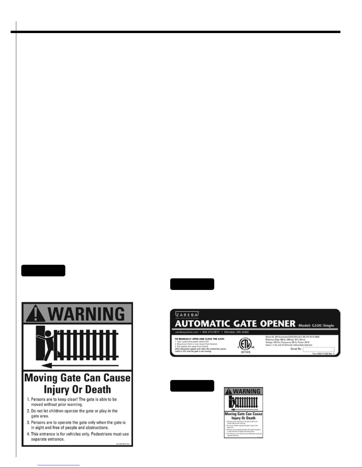
Warning Signs (fig. 3-5)
The warning signs must be installed on both sides of
the gate.
Figure 3
Warning signs (two enclosed) to be installed
on each side of the gate (three to five feet
above the bottom of the gate)
These warning signs and labels must appear at the locations specified below. If any were missing when the gate
opener was purchased, immediately contact Zareba
Systems for replacements.
Figure 4
Product identification and manual operation instruction label
installed on control box cover
Figure 5
Warning labels, one
on each side of gate
opener arm
8
SMART SYSTEMS FOR ACCESS CONTROL
Additional Safety Devices
Contact Sensors (safety edges) (fig. 6)
The Zareba Automatic Gate Opener features built-in
obstruction sensitivity. The opener is designed to stop
and reverse the gate within two seconds of contact with
an obstruction. However, the gate opener’s built-in
obstruction settings, even when properly adjusted, may
not be sensitive enough to prevent injury in some circumstances. See page 32 for more information.
Safety devices, such as contact (safety edge) sensors or
non-contact (photoelectric) sensors, that stop and
reverse gate direction upon sensing an obstruction are
suggested for additional protection.
Zareba Systems recommends using additional safety
devices. Be sure to use products that are certified and
that comply with applicable UL standards and national
and regional safety codes. Call Zareba Systems at
1-800-272-9877 for information on compatible products for your application.
Important: In all cases, review the safety-device manufacturer’s instructions for information on installing these
devices on a vehicular gate.
Contact sensors are also referred to as “safety edges.”
Activating a properly installed contact sensor while the
gate is moving causes the gate to stop and reverse within two seconds.
Contact sensors must be mounted in compliance with
UL 325, the Underwriters Laboratories safety standard
for gate openers.
Turn off the power switch to the opener
(actuator) before connecting safety device
!
wiring to the terminal blocks. Unplugging
the transformer does not turn off power to
the opener.
Figure 6
Contact Sensor (not included)
9

G550 Automatic Gate Opener Installation Manual
Contact Sensor Input Connection (fig. 7)
Connect one of the SAFETY contact sensor wires to the
COMMON (COM) terminal and the other to the
SAFETY terminal on the gate opener control board.
Non-Contact Sensors (photoelectric beams)
Non-contact sensors, also called photoelectric beams,
enhance safety by monitoring the path of the safety
beam when the gate is closing. Obstructing the safety
beam path activates the non-contact sensor, which
reverses the gate to the fully open position.
Figure 7
wire from contact sensor
Non-Contact Sensor Connection (fig. 8)
Connect one of the non-contact sensor dry contact output wires to the COMMON (COM) terminal and the
other to the SAFETY terminal on the gate opener control
board.
Figure 8
wire from non-contact
sensor (photo beam)
10

SMART SYSTEMS FOR ACCESS CONTROL
PRE-INSTALLATION
INFORMATION
Tools and Parts List
Tools needed
• Power drill
• Open-end wrenches — 3/8”, 7/16”, 1/2”, and 9/16”
• 3/8” Drill bit
• Hacksaw or heavy-duty bolt cutters
• Small (flat-bladed) screwdriver
• Phillips screwdriver
• Tape measure
• Level
• Wire strippers (for stripping the transformer cable)
• C-clamps
Other Items You May Need for Installation
• Low-voltage wire. This is needed to run from the
transformer to the control box. You’ll need enough to
cover the distance between the transformer power
supply and the control box. See Powering Information
on page 34 and Gate Opener Accessories on page 40.
• Solar Panel(s). If your gate is more than 1,000’ away
from an AC power source, you will need at least one
Solar Panel to trickle charge the battery. See Gate
Opener Accessories on page 40.
• Threaded rods or carriage bolts longer than 8”.
You will need these if your fence post is more than 6”
in diameter.
• Reinforcement supplies. If you have thin-walled tube
or panel gates, use wood or metal reinforcement
plates or pipes.
• A horizontal cross member or mounting plate. A
horizontal cross member or mounting plate may be
necessary on some types of gates. This would mount
the front of the opener and gate bracket to the gate.
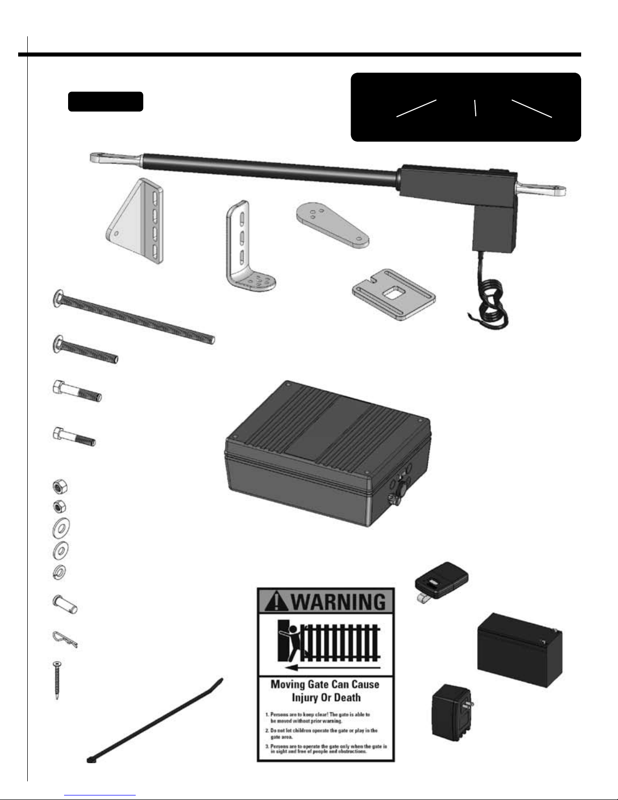
Parts (fig. 9)
Mounting hardware
Hairpin clip (2); 3/8” x 1-1/4” Clevis pin (2); 5/16” x
1-3/4” Bolt (1); 3/8” x 2” Bolt (1); 3/8” x 3” Bolt (2);
3/8” x 8” Bolt (6); 8” Nylon cable tie (14); 3/8” Washer
(10); 3/8” Lock washer (10); 5/16” Washer (1); 3/8”
Nut (10); 5/16” Nut (1); 2” Mounting screw (5)
Gate Opener
Gate opener (actuator) (1) with 10’ power cable; Gate
bracket (1); Pivot bracket (1); Post bracket (2); Closedposition stop plate (1)
Control Box and Electrical Components
Transformer (1); Battery (1); Control box (1); Warning
signs (2); Transmitter (1)
11
G550 Automatic Gate Opener Installation Manual
HOW TO READ PART LABELS:
Figure 9
Post Bracket (2) (7001217.001)
Gate opener (actuator) with 10’ power cable (1) (7001618.001)
Gate bracket (1)
(7001215.001)
3/8” x 8” Bolt (6) (7001237.001)
3/8” x 3” Bolt (4) (7001220.001)
3/8” x 2” Bolt (1) (7001221.001)
Pivot bracket (1)
(7001218.001)
Post bracket (2)
(7001217.001)
part description
Closed-position stop plate (1)
(7001216.001)
Control box (1)
(7001620.001)
included
part quantity
order item
number
5/16” x 1-3/4” Bolt (1) (7001222.001)
3/8” Nut (10)(7001229.001)
5/16” Nut (1) (7001230.001)
3/8” Washer (10) (7001226.001)
5/16” Washer (1) (7001228.001)
3/8” Lock washer (10) (7001227.001)
3/8” x 1-1/4” Clevis pin (2)
(7001223.001)
Clevis pin clip (2)
(7001224.001)
2” Mounting screw (5)
(7001225.001)
Warning signs (2)
(7001181.001)
Transmitter (1)
(7001213.001)
Battery (1)
(7001155.001)
8” Nylon cable tie (14)
(7001231.001)
Transformer (1)
(7001212.001)
12
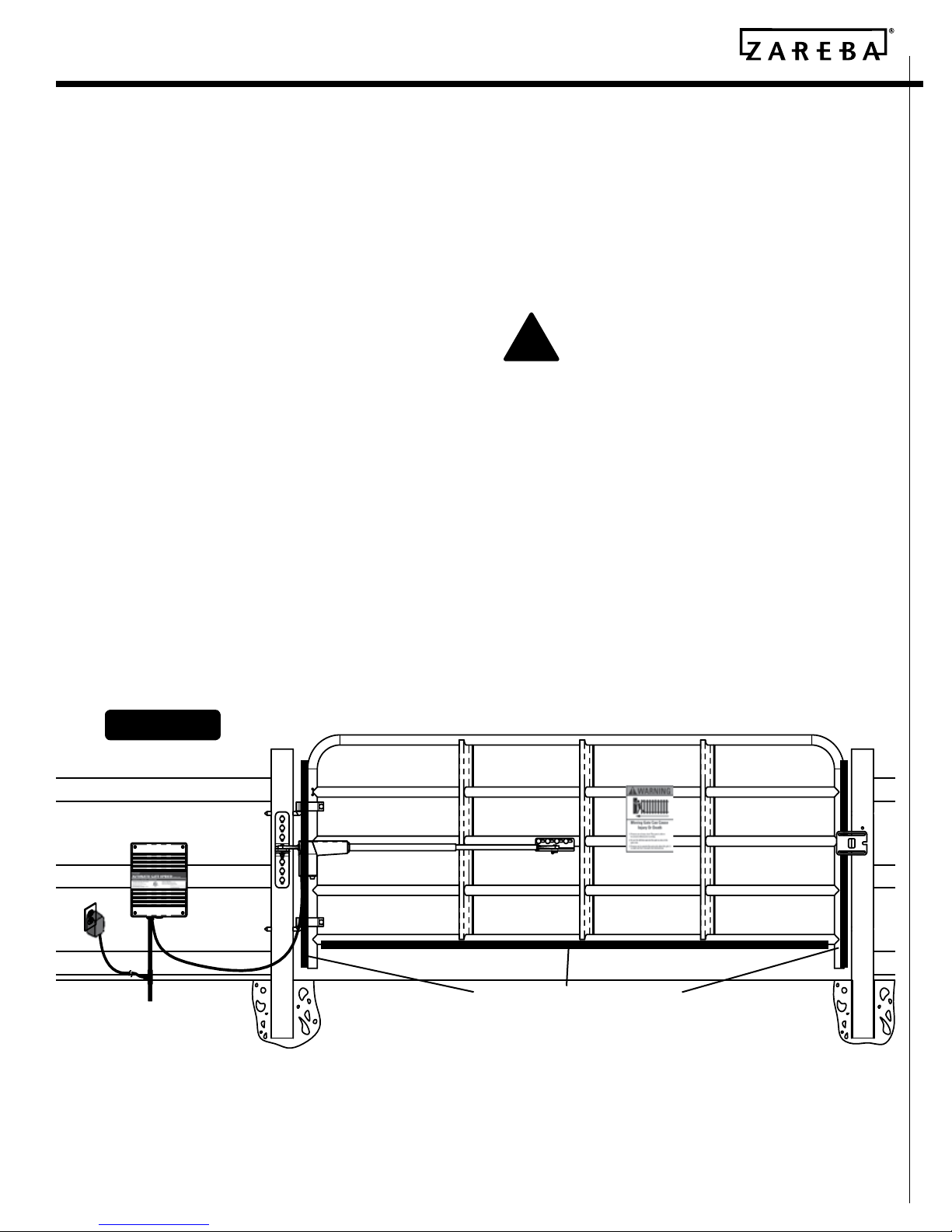
SMART SYSTEMS FOR ACCESS CONTROL
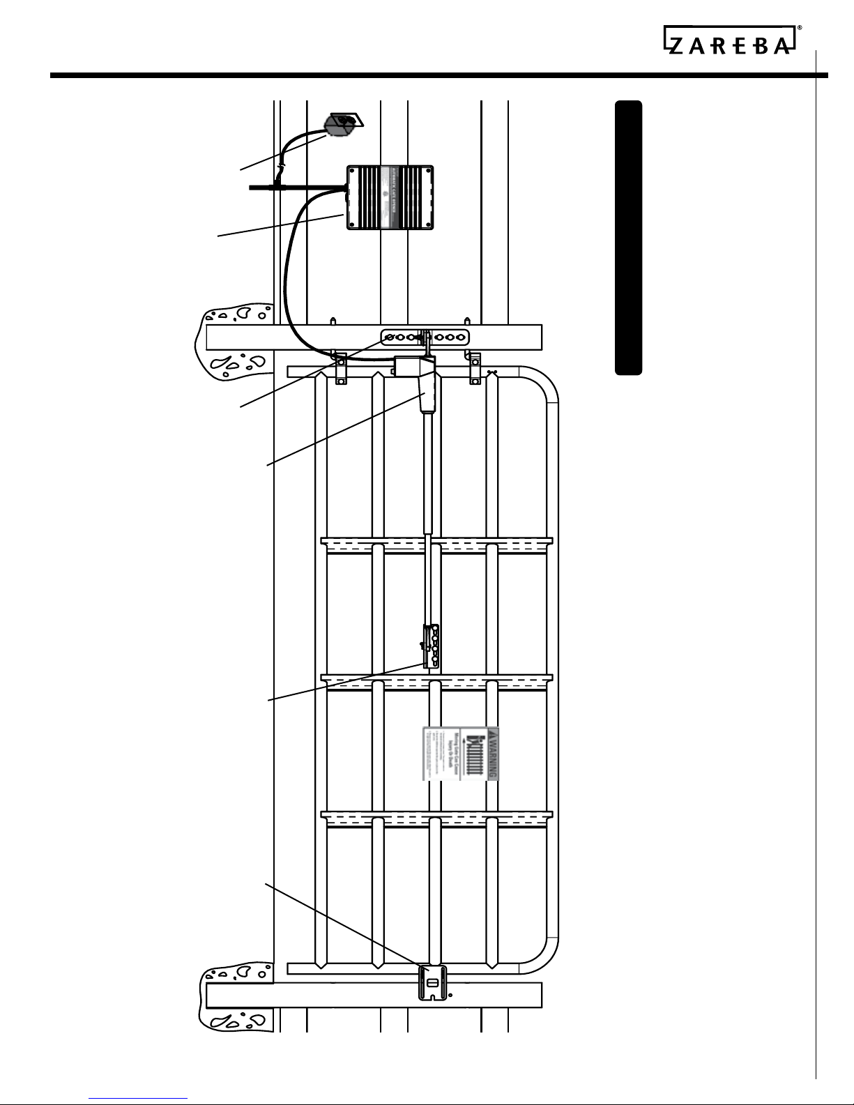
Transformer
Control box
Post bracket
Installed Gate Opener Overview
Gate opener (actuator)
Gate bracket
Closed-position
stop plate
13
 Loading...