

Zanussi ZHC7141 User Manual [ru]
User
Manual
Bedienungs
anleitung
Manuel d’Instruc-
tions
Gebruiksaanwi-
jzing
Manual de in-
strucciones
Manual de In-
Инструкция
по монтажу и
struções
эксплуатации
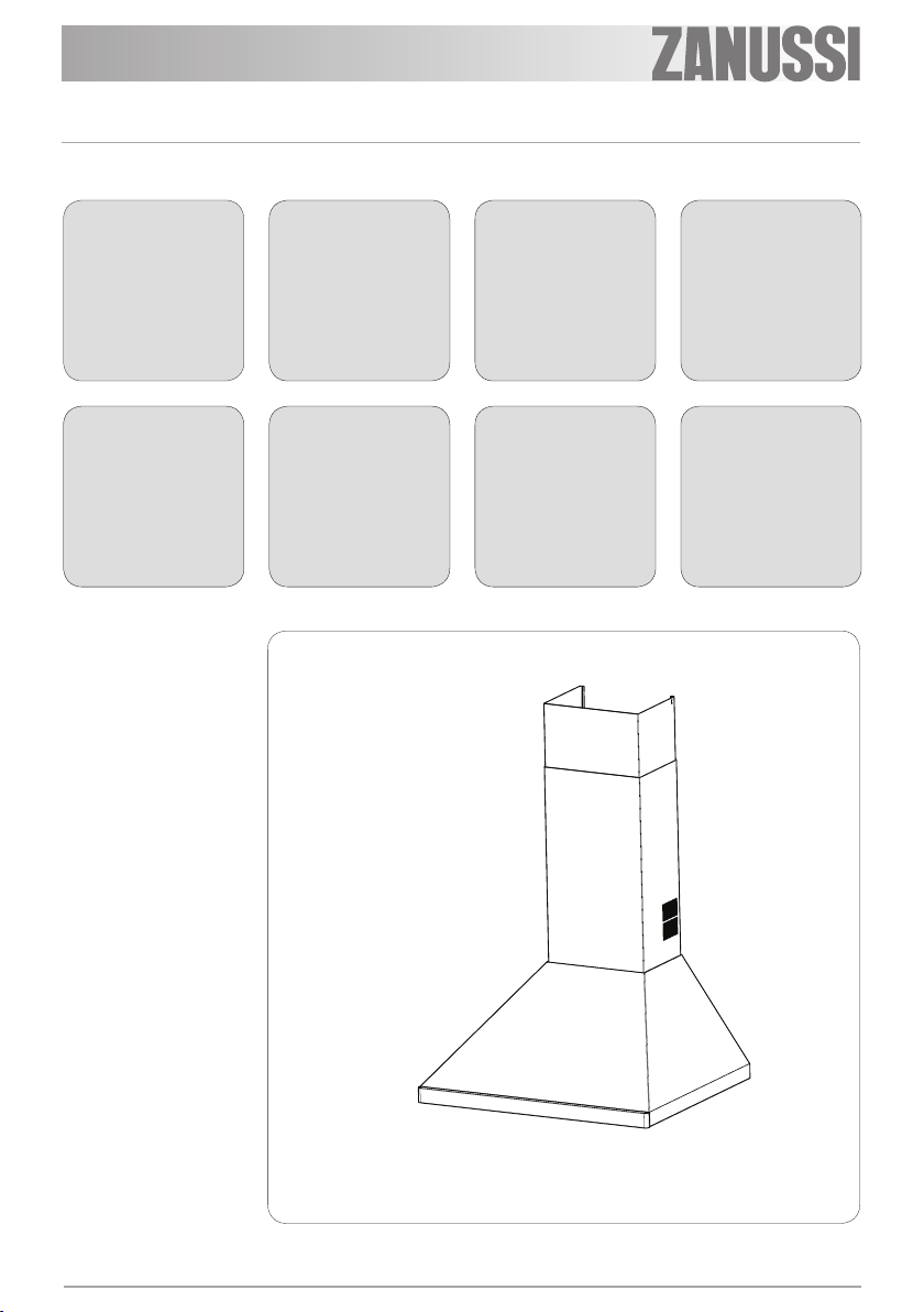
Model ZHC6141
Model ZHC7141
Model ZHC9141

EN
Instructions Manual
INDEX
WARNINGS - COMPONENTS...............................................................................................................................................8
INSTALLATION ......................................................................................................................................................................9
USE - MAINTENANCE.........................................................................................................................................................10
2
2

DE
Bedienungsanleitung
INHALTSVERZEICHNIS
HINWEIS - KOMPONENTEN...............................................................................................................................................11
MONTAGE............................................................................................................................................................................12
BEDIENUNG - WARTUNG..................................................................................................................................................13
3
3

FR
Manuel d’Instructions
SOMMAIRE
ATTENTION - COMPOSANTS.............................................................................................................................................14
INSTALLATION ....................................................................................................................................................................15
UTILISATION - ENTRETIEN................................................................................................................................................16
4
4

NL
Gebruiksaanwijzing
INHOUDSOPGAVE
AANWIJZINGEN - ONDERDELEN......................................................................................................................................17
INSTALLATIE .......................................................................................................................................................................18
GEBRUIK - ONDERHOUD...................................................................................................................................................19
5
5

ES 6 6
Инструкция по монтажу и эксплуатации
ÍNDICE
ADVERTENCIAS - COMPONENTES..................................................................................................................................20
INSTALACIÓN......................................................................................................................................................................21
USO - MANTENIMIENTO.....................................................................................................................................................22

PT 7 7
Manual de Instruções
ÍNDICE
ADVERTÊNCIAS - COMPONENTES..................................................................................................................................23
INSTALAÇÃO.......................................................................................................................................................................24
UTILIZAÇÃO - MANUTENÇÃO............................................................................................................................................25

PT 8 8
Manual de Instruções
УКАЗАТЕЛЬ
ПРАВИЛА ТЕХНИКИ БЕЗОПАСНОСТИ - ПРИНАДЛЕЖНОСТИ....................................................................................26
УСТАНОВКА........................................................................................................................................................................27
ЭКСПЛУАТАЦИЯ - ТЕХНИЧЕСКОЕ ОБСЛУЖИВАНИЕ ..................................................................................................28
EN
WARNINGS - COMPONENTS
WARNINGS
This appli ance has been d esigned for use as ei ther an EXTRACTION (ducti ng to the outside) or RECIRCULATION (filtering) hood. The measurements contained on the drawings in this booklet refer to
two models of cooker hood. Therefore, it is essential that you refer to the correct drawing when taking
measurements for installation.
- The minimum distan ce between the cooking surface and the metal grea se filters on the unde rside of the
hood must be 650 mm.
- This cooker hood must be installed in accordance with the installation instructions and all requirements
must be adhered to.
- If the room where the cooker hood is to be used contains a fuel burning appliance such as a central heating boiler th en its flue must be of the room sealed or balance flue type.
- If other types of flue or appliances ar e fitted ensure that there is an adequate supply of air to the room.
- When the range hood and appliance supplied with energy other than electricity are simultaneously in
operation, t he negative pr essure in the room must not exceed 4 Pa (4x1 0-5 bar).
- Exhaust air may be discharged in accordance with official and statutory regulations only (e.g. national building regulations).
- The ducting system for this appliance must not be connected to any ventilation system which is being
used for any other purpose.
- The ducting system for this appliance must not be connected to any existing ventilation system which is
being used for any other purpose.
- Do not leave naked flames or carry out flambè cooking under this cooker hood.
- This appliance is not intended for use by persons (including children) with reduced physical, sensory or
mental capabilitie s, or lac k of expe rience and k nowledge, unless the y have b een given s upervision or instruction concerning us e of the appli ance by a person responsible for their safety.
- Children should be supervised to ensure that they do not play with the applia nce
The symbol on the product or on i ts pack agi ng indi cat es t hat thi s pr o duct m ay n ot be tr e at ed a s ho usehold waste. Ins tea d it s hal l
be handed over to the appl icable c ollectio n point for t he recycli ng of electr ical and electronic equipm ent. By ensur ing this pr oduct is
disposed of correctly, you will help prevent potential negative consequences for the environment and human health, which could otherwise be c aused by inappr opr i a te waste handl i ng of this product. F or m ore detailed i nformation about recycling o f this product, please contact your local city office, your household waste disposal service or the shop where you purchased the product.
CONNECTING THE POWER CABLE TO THE MAINS POWER SUPPLY
Before installation, check that the mains voltage indicated on the rating plate inside the appliance corresponds to the voltage available in your home. If the Hood is not fitted with a plug, fit the power cable with
a plug of a type approved for the load indicated on the rating plate; when connecting directly to the mains,
insert an omnipolar circuit breaker with a minimum contact aperture of 3mm and a size suitable for the
load in question between the appliance and the mains supply, making sure it is of a type that complies with
current regulation s.
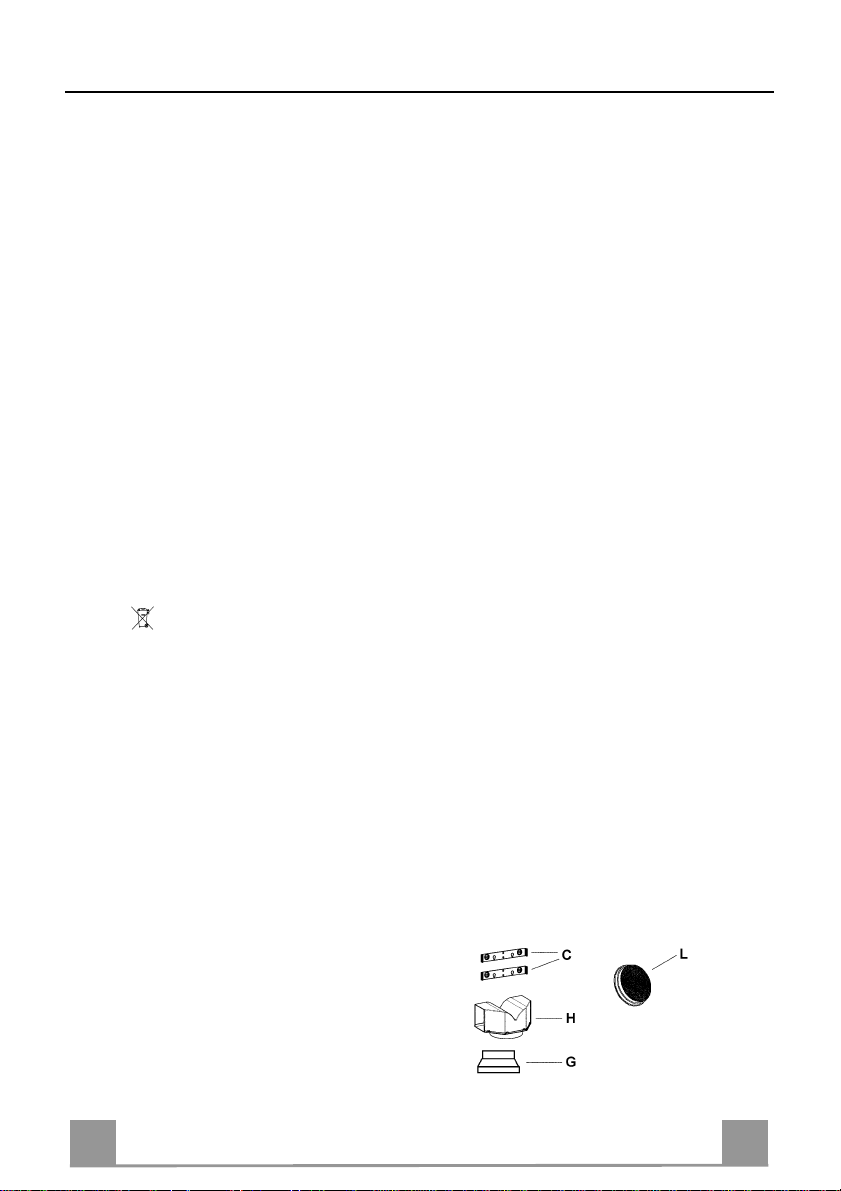
COMPONENTS
- 2 No Wall Brackets C
- 1 No 150-120mm Ducting Spigot G
- 1 No Air Outlet Connection H (Optional)
- 2 No Charcoal F i lters L (Optional)
9
9

EN 110
INSTALLATION
The cooker hood must be installed centrally over a cooking appliance. The minimum distance
between the cooking surface and the metal grease filters on the underside of the hood must be
at least 650mm.
To install the hood proceed as follows:
1) Drill six 8mm diameter holes at X1-X2-J and insert the plastic rawl plugs supplied as illus-
trated in fig. 2 ensuring the brackets are fitted as shown in the blow up.
2) Secure the two brackets C to the wall inserting two of the screws supplied through the two
holes on line X1-X2 as illustrated in fig. 2.
3) Slide the canopy down the wall to locate the key hole over the washer then secure the can-
opy to the wall by inserting two of the screws supplied through the two outer holes in the
rim of the canopy J1 and J2 as illustrated in fig. 3.
4) EXTRACTION OR RECIRCULATION INSTALLATION:
• EXTRACTION (DUCTED)
When installing the ducted version, connect the hood to the chimney using either a flexible or
rigid pipe ø 150 or 120 mm, the choice of which is left to the installer.
• To install a ø 120 mm air exhaust connection, insert the reducer flange 9 on the hood body
outlet.
• Fix the pipe in position using sufficient pipe clamps (not supplied).
• Remove an y activated charcoal filters.
• RECIRCULATION (FILTERED)
• When the hood is fitted in the recirculation mode the Air Outlet Connection H should be
fitted as illustrated in fig. 6.
• Fit the (o ptional) charcoal filters by repeating the following operation on each side of the
motor housing. Place the two key hole slots in the filter L and turn the filter clockwise to
lock the filter in position as illustrated in fig. 7.
WARNING: It is a possible fire hazard if the metal grease filters are not cleaned and the
charcoal filters replaced regularly.
Fitting The Chimney
5) FITTING THE CHIMNEY UPPER
To fit the upper chimney A, place the top edge of the ch imney ov er the b racket C as illus-
trated in fig. 8 and secure the chimney using two of the 2.9mm self tapping screws provided.
The distance H in the height between the fixing holes X1 and X2 is determined by the
height of the upper chimney A.
6) FI TTI N G THE CHI M N EY LOW E R
To fit the lower chimney B, apply slight force to the two rear edges to in crease the width
of the apperture, then sleeve the chimney B over the chimney A as illustrated in fig. 9.
 Loading...