

Page 1

Cappa
Campana
Cooker hood
Hotte de cuisine
Exaustor
Απορροφητήρας
Dunstabzugshaube
Dampkap
ZHC 600 - ZHC 900
ZHC 605 - ZHC 905
MANUALE DI INSTALLAZI ONE, USO E MANUTENZION E
INSTALLATION, USE AND MAINTENANCE HANDBOOK
MANUEL D’INSTRUCTIONS POUR L’INSTALLATION, L’EMPLOI ET L’ENTRETIEN
HANDBUCH FÜR INSTALLATION, BEDIENUNG UND WARTUNG
INSTRUCTIES VOOR MONTAGE, GEBRUIK EN ONDERHOUD
MANUAL DE INSTRUCCIONES
MANUAL DE INSTRUÇÕES
Οδηγίες χρήσης και εγκατάστασης
Page 2

IT
Libretto di Istruzioni
INDICE
CONSIGLI E SUGGERIMENTI ............................................................................................................................................10
CARATTERISTICHE............................................................................................................................................................11
INSTALLAZIONE..................................................................................................................................................................12
USO......................................................................................................................................................................................15
MANUTENZIONE.................................................................................................................................................................16
2
2
Page 3

EN
Instructions Manual
INDEX
RECOMMENDATIONS AND SUGGESTIONS....................................................................................................................18
CHARACTERISTICS............................................................................................................................................................19
INSTALLATION ....................................................................................................................................................................20
USE.......................................................................................................................................................................................23
MAINTENANCE....................................................................................................................................................................24
3
3
Page 4

FR
Manuel d’Instructions
SOMMAIRE
CONSEILS ET SUGGESTIONS ..........................................................................................................................................26
CARACTERISTIQUES.........................................................................................................................................................27
INSTALLATION ....................................................................................................................................................................28
UTILISATION........................................................................................................................................................................31
ENTRETIEN..........................................................................................................................................................................32
4
4
Page 5

DE
Bedienungsanleitung
INHALTSVERZEICHNIS
EMPFEHLUNGEN UND HINWEISE....................................................................................................................................34
CHARAKTERISTIKEN..........................................................................................................................................................35
MONTAGE............................................................................................................................................................................36
BEDIENUNG.........................................................................................................................................................................39
WARTUNG............................................................................................................................................................................40
5
5
Page 6

NL
Gebruiksaanwijzing
INHOUDSOPGAVE
ADVIEZEN EN SUGGESTIES.............................................................................................................................................42
EIGENSCHAPPEN...............................................................................................................................................................43
INSTALLATIE .......................................................................................................................................................................44
GEBRUIK..............................................................................................................................................................................47
ONDERHOUD ......................................................................................................................................................................48
6
6
Page 7

ES
Manual de instrucciones
ÍNDICE
CONSEJOS Y SUGERENCIAS ...........................................................................................................................................50
CARACTERÍSTICAS............................................................................................................................................................51
INSTALACIÓN......................................................................................................................................................................52
USO......................................................................................................................................................................................55
MANTENIMIENTO................................................................................................................................................................56
7
7
Page 8

PT
Manual de Instruções
ÍNDICE
CONSELHOS E SUGESTÕES............................................................................................................................................58
CARACTERÍSTICAS............................................................................................................................................................59
INSTALAÇÃO.......................................................................................................................................................................60
UTILIZAÇÃO.........................................................................................................................................................................63
MANUTENÇÃO....................................................................................................................................................................64
8
8
Page 9

GR
Εγχειρίδιο οδηγιών
ΠΕΡΙΕΧΟΜΕΝΑ
ΣΥΜΒΟΥΛΕΣ ΚΑΙ ΣΥΣΤΑΣΕΙΣ.............................................................................................................................................66
ΧΑΡΑΚΤΗΡΙΣΤΙΚΑ................................................................................................................................................................67
ΕΓΚΑΤΑΣΤΑΣΗ.....................................................................................................................................................................68
ΧΡΗΣΗ..................................................................................................................................................................................71
ΣΥΝΤΗΡΗΣΗ ........................................................................................................................................................................72
9
9
Page 10

IT 110
CONSIGLI E SUGGERIMENTI
INSTALLAZIONE
• Il produttore declina qualsiasi responsabilità per danni dovuti ad installazione non corretta o non conforme alle regole dell’arte.
• La distanza minima di sicurezz a tra il Piano di cottura e la Ca ppa deve essere di 650 mm.
• Verificare che la tensione di rete corrisponda a quel la riportata nella
targhetta posta all’interno della Cappa.
• Per Apparecchi in Classe Ia accertarsi che l’impianto elettric o domestico garantisca un corretto scarico a terra.
• Collegare la Cappa all’uscita dell’aria aspirata con tubazione di diametro pari o superiore a 120 mm. Il p erc orso della tubazione deve essere il più breve possibile.
• Non collegare la Cappa a condotti di scarico dei fumi prodotti da
combustione (caldaie, caminetti, ecc.).
• Nel caso in cui nella stanza vengano utilizzati sia la Cappa che apparecchi non azionati da energia elettrica (ad esempio apparecchi utilizzatori di gas), si deve provvedere ad una aerazione sufficiente
dell’ambiente. Se la cucina ne fosse sprovvista, praticare un’apertura
che comunichi con l’esterno, per garantire il richiamo d’aria pulita.
USO
• La Cappa è stata prog ettata esclusivamente per uso domestic o, per
abbattere gli odori della cucina.
• Non fare mai uso improprio della Cappa.
• Non lasciare fi amme libere a forte intensità sotto l a Cappa in funzione.
• Regolare sempre le fi amme in modo da evitare una evident e fuoriuscita laterale delle stesse rispetto al fondo delle pentole.
• Controllare le friggitri ci durante l’uso: l’olio surriscaldato potrebbe infiammarsi.
• Non preparare alimenti fl ambè sotto l a c appa da cuc ina; pericol o d'incendio.
• La Cappa non deve essere utilizzata da bambini o persone non abilitate all’uso corretto.
MANUTENZIONE
• Prima di procedere a qualsiasi opera zione di manutenzione, di sinseri re la Cappa togliendo la spina elettrica o spegn endo l’interruttore generale.
• Effettuare una scrupolosa e tempestiva manutenzione dei Filtri secondo gli intervalli consigliati.
• Per la pulizia delle superfici della Cappa è sufficiente utilizzare un
panno umido e detersivo liquido neutro.
650 mm min.
Page 11
IT 111
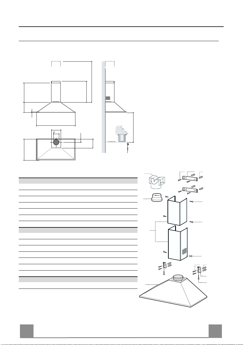
CARATTERISTICHE
560
240
18
598 - 698 - 898
210
150
490
100
Ingombro
max. 765
min. 560
650 min.
205
Componenti
Rif. Q.tà Componenti di Prodotto
1 1 Corpo Cappa completo di: Comandi, Luce , Filtri
2 1 Ca mino Telescopico formato da:
2.1 1 Camino Superiore
2.2 1 Camino Inferiore
9 1 Flangia di Riduzione ø 150-120 mm
15 1 Raccordo Uscita Aria
Rif. Q.tà Componenti di Installazione
7.1 2 Staffe Fissaggio Corpo Cappa
7.2.1 2 Staffe Fiss aggi o Camino Superiore
11 8 Tasselli
12a 8 Viti 4,2 x 44,4
12c 6 Viti 2,9 x 9,5
12d 2 Viti M4 x 25
Q.tà Documentazione
1 Libretto Istruzioni
15
9
2.1
2
2.2
1
12a 11
7.2.1
12c
12c
12c
12a 11
7.1
12d
Page 12
IT 112
INSTALLAZIONE
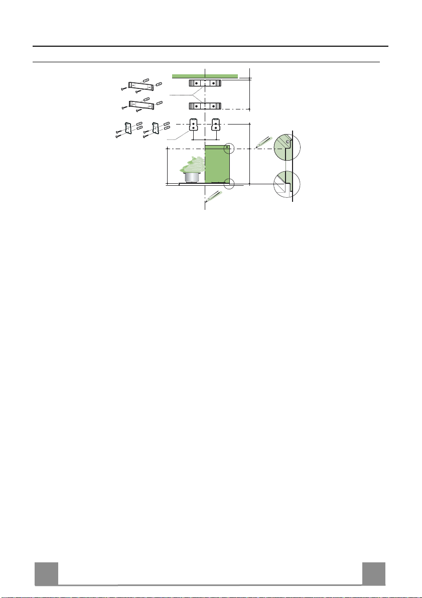
Foratura Parete e Fissaggio Staffe
1÷2
7.2.1
X
7.1
95
95
210
650 min.
H
Tracciare sulla Parete:
• una linea Verticale fino al soffitto o al limite superiore, al centro della zona prevista per il
montaggio della Cappa;
• una linea Orizzontale a: 650 mm min. sopra il Piano di Cottura, per installazione senza Fondale; alla quota H (H=altezza del la parte in vista del Fondale), per instal lazione con Fondale.
• Appoggiare come ind icat o l a Staffa 7.2.1 a 1-2 mm dal soffitto o dal limite superiore, allineando il suo centro (intagli) sulla linea Verticale di riferimento.
• Segnare i centri dei Fori della Staffa.
• Appoggiare come indi cato la S taffa 7.2.1 a X mm sotto la pri ma staffa (X = altezza Camino
Superiore in dotazione), allineando il suo centro (intagli) sulla linea Verticale di riferimento.
• Segnare i centri dei Fori della Staffa.
• Appoggiare come indi cato, la S taffa 7.1 a 95 mm dalla linea Verticale di riferimento, e 210
mm sopra la linea Orizzontale di riferimento.
• Segnare i centri dei Fori della Staffa.
• Ripetere questa operazione dalla parte opposta.
FONDALE (OPTIONAL)
Il Fondale va montato prima di montare il Corpo Cappa e, se si desidera fissarlo alla parete sia
superiormente che inferiormente, è necessario mon tarlo alla giust a altezza, prima del montaggio delle basi. Essendo questa operazione complessa va effettuata solamente dall’installatore
della cucina o da personale competente che conosca tutte le dimensioni finali dei mobili.
Limitandosi al solo fissaggio superiore, procedere come segue:
• Appoggiare il Fondale sulla base inserendo la faldina inferiore tra il piano superiore e la parete,
centrandolo sulla linea Verticale di riferimento.
• Segnare i centri dei due fori della faldina superiore.
• Forare ø 8 mm i punti segnati.
• Inserire i tasselli 11 nei fori.
• Fissare le Staffe, utilizzando le Viti 12a (4,2 x 44,4 ) in dotazione.
• Se presente, fissare il Fondale, utilizzando le Viti 12a (4,2 x 44,4) in dotazione.
Page 13
IT 113
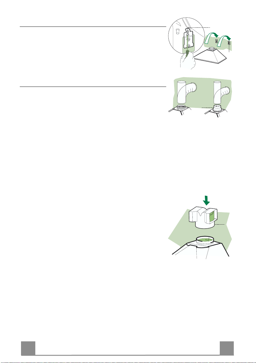
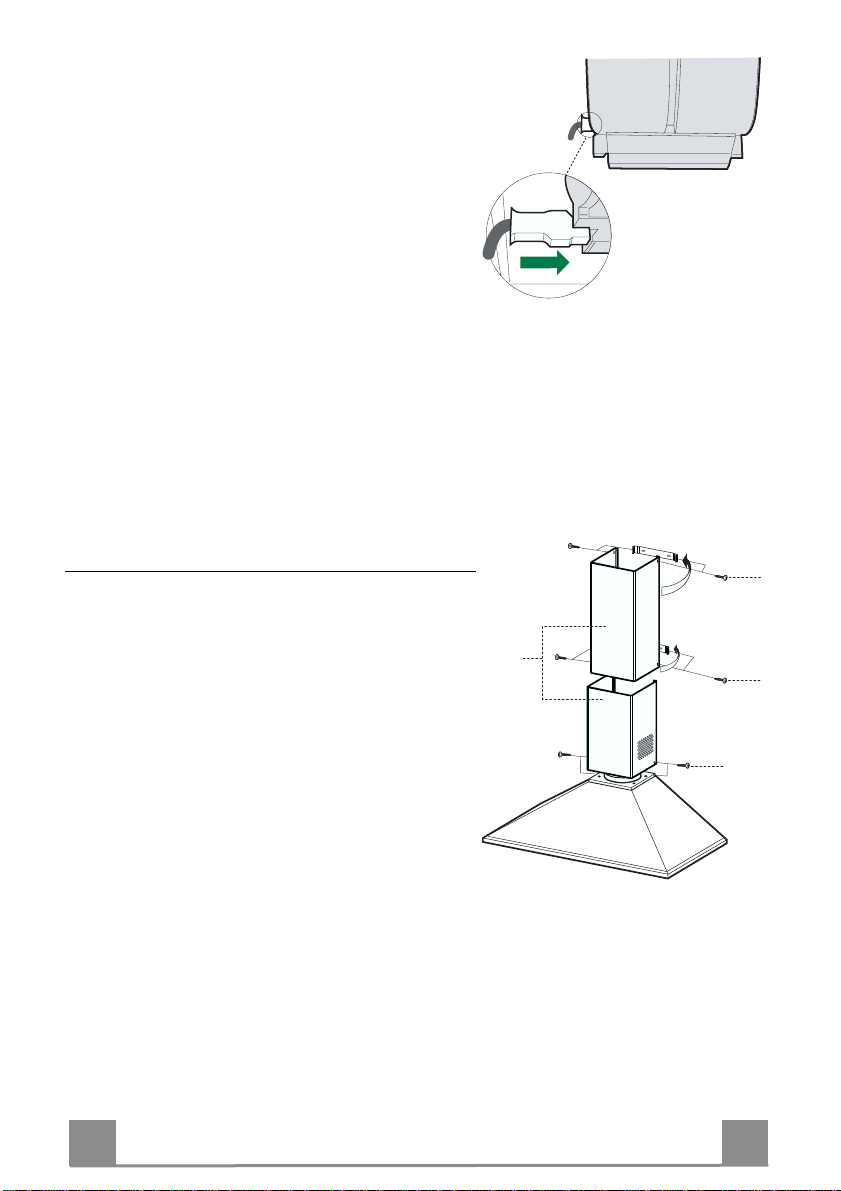
Montaggio Corpo Cappa
7.1
12.d
15
• Avvitare sulle Staffe 7.1, le 2 Viti 12d in dotazione.
• Agganciare il Corpo Cappa alle Staffe 7.1, centrandolo sulla
linea verticale.
• Agire sulle Viti 12d, dal sotto della Cappa, per livellare il Corpo Cappa.
Connessioni
USCITA ARIA VERSIONE ASPIRANTE
Per installazione in Versione Aspirante collegare la Cappa alla
tubazione di uscita per mezzo di un tubo rigido o flessibile di
ø150 o 120 mm, la cui scelta è lasciata all'installatore.
• Per collegamento con tubo ø120 mm, inserire la Flangia di riduzione 9 sull’Uscita del Corpo Cappa.
• Fissare il tubo con adeguate fascette stringitubo. Il materiale
occorrente non è in dotazione.
• Togliere eventuali Filtri Antiodore al Carbone attivo.
ø 120ø 150
9
USCITA ARIA VERSIONE FILTRANTE
• Applicare a pressione il Raccordo Uscita Aria 15 sull’Uscita
del Corpo Cappa.
• Assicurarsi della presenza del Filtro Antiodore al Carbone attivo.
Page 14

IT 114
CONNESSIONE ELETTRICA
• Collegare la Cappa all’Alimentazione di Rete interponendo un Interruttore bipolare con apertura dei
contatti di almeno 3 mm.
• Rimuovere i Filtri antigrasso (vedi par. “Manutenzione”) e assicurarsi che il connettore del Cavo di alimentazione sia correttamente inserito nella presa
dell’Aspiratore
Montaggio Camino
Camino superiore
• Allargare leggermente le due falde laterali, agganciarle dietro le Staffe 7.2.1 e richiuderle fino a battuta.
• Fissare lateralmente alle Staffe con 4 Viti 12c (2,9 x
9,5) in dotazione.
Camino inferiore
• Allargare leggermente le due falde laterali del Camino, agganciarle tra il Camino superiore e la parete e
richiuderle fino a battuta.
• Fissare lateralmente la parte inferiore al Corpo Cappa, con 2 Viti 12c (2,9 x 9,5) in dotazione.
• Assicurarsi che l’uscita del Raccordo 15 risulti in
corrispondenza delle bocchette del Camino.
12c
2.2
2
12c
2.1
12c
Page 15

IT 115
USO
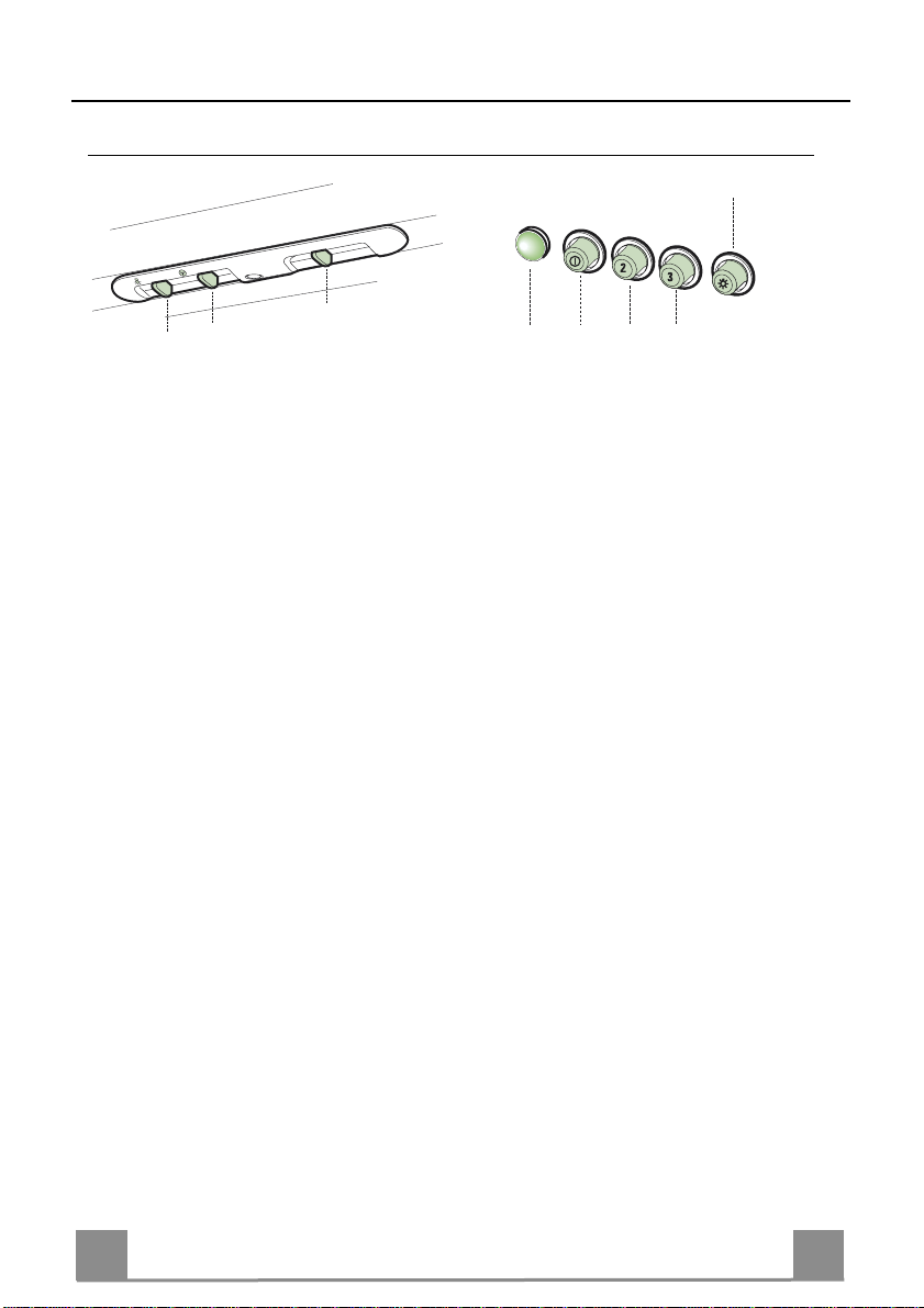
Quadro comandi
3
2
1
0
1
0
M
L
L Luci Accende e spegne l’Impianto
di Illuminazione.
M Motore Accende e spegne il motore
Aspirazione.
V Velocità Determina la velocità di e-
sercizio:
1. Velocità minima, adatta
ad un ricambio d’aria
continuo particolarmente
silenzioso, in presenza di
pochi vapori di cottura.
2. Velocità media, adatta
alla maggior parte delle
condizioni d’uso, dato
l’ottimo rapporto tra portata d’aria trattata e livello sonoro.
3. Velocità massima, adatta
a fronteggiare le massime
emissioni di vapore di
cottura, anche per tempi
prolungati.
1
V
L
S
V1 V2 V3
L Luci Accende e spegne l’Impianto
di Illuminazione.
S Led Led accensione Motore.
V1 Motore Accende e spegne il motore
Aspirazione a velocità mini-
ma, adatta ad un ricambio
d’aria continuo particolarmente silenzioso, in presenza
di pochi vapori di cottura.
V2 Velocità V elocità media, adatta alla
maggior parte delle condizioni d’uso, dato l’ottimo
rapporto tra portata d’aria
trattata e livello sonoro.
V3 Velocità Velocità massima, adatta a
fronteggiare le massime emissioni di vapore di cott ura ,
anche per tempi prolungati.
Page 16
IT 116
MANUTENZIONE
A
B
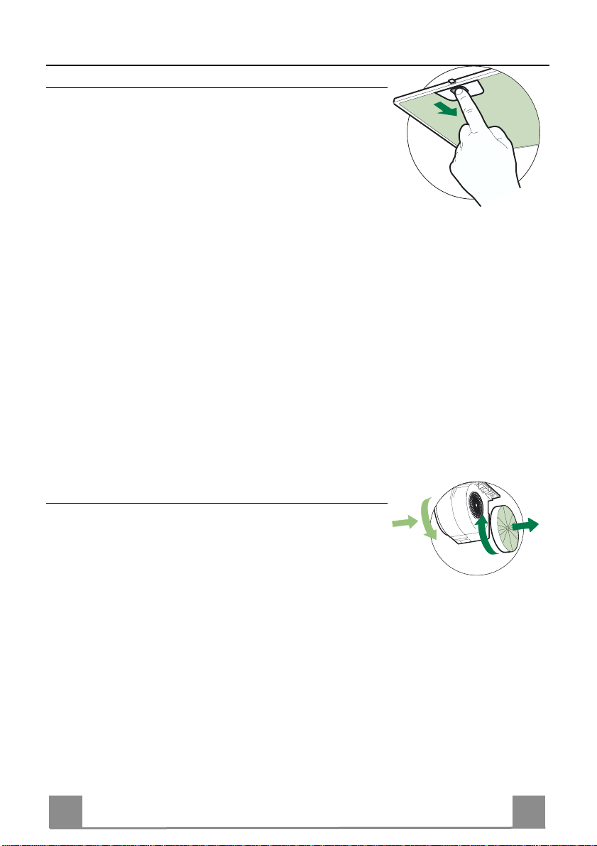
Filtri antigrasso
PULIZIA FILTRI ANTI GR A SSO META L L ICI AUTO PO RTAN TI
• Sono lavabili anche in lavastoviglie, e necessitano di essere
lavati ogni 2 mesi circa di utilizzo o più frequentemente, per un
uso particolarmente intenso.
• Togliere i Filtri uno alla volta, spingendoli verso la parte posteriore del gruppo e tir ando contemporaneamente verso il basso.
• Lavare i Filtri evitando di piegarli, e lasciarli asciugare prima
di rimontarli.
• Rimontarli facendo attenzione a mantenere la maniglia verso la
parte visibile esterna
Filtri antiodore al Carbone attivo (Versione Filtrante)
Il Filtro antiodore al Carbone attivo non è lavabile e non è rigenerabile, va sostituito ogni 4 mesi circa di utilizzo o più frequentemente, per un uso particolarmente intenso.
SOSTITUZIONE
• Togliere i Filtri antigrasso.
• Rimuovere i Filtri antiodore al Carbone attivo saturi, come indicato (A).
• Montare i nuovi Filtri, come indicato (B).
• Rimontare i Filtri antigrasso.
Page 17
IT 117
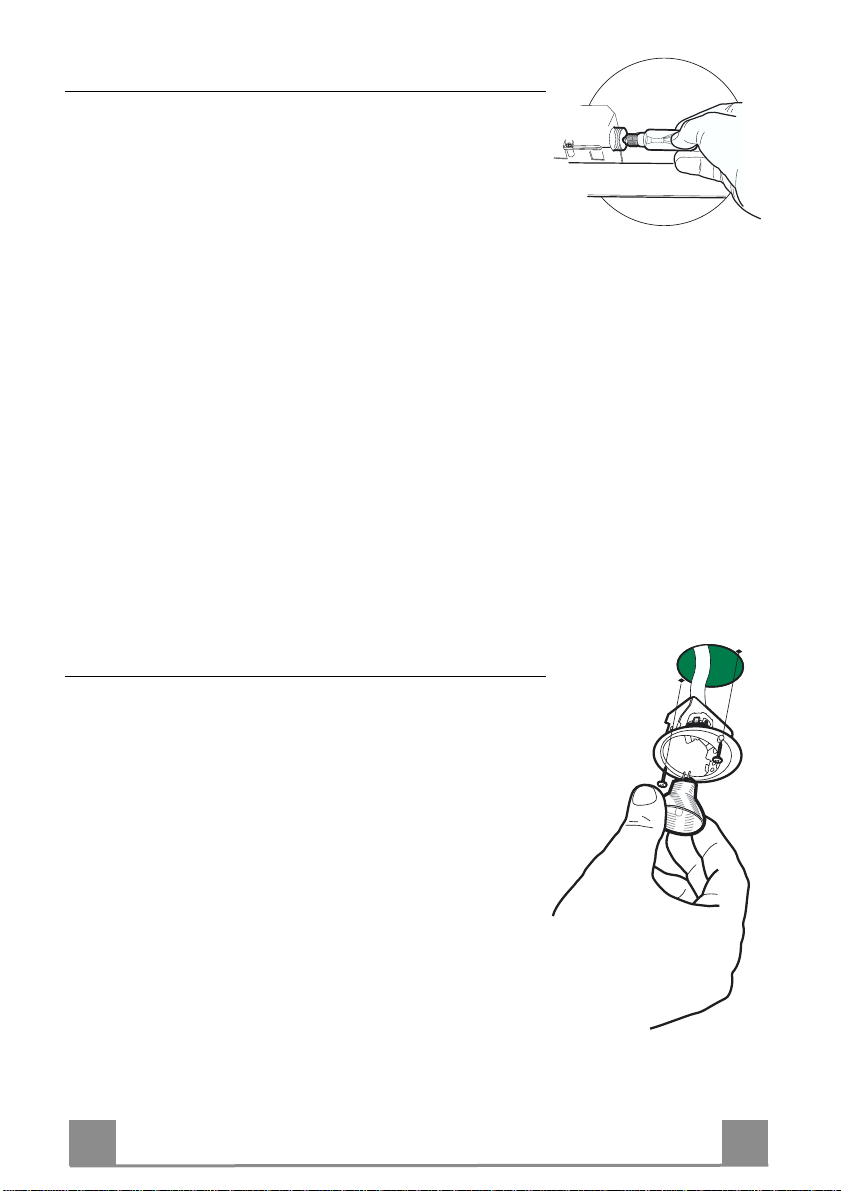
Illuminazione
SOSTITUZIONE LAMPADE
Lampade a incandescenz a da 40 W
• Togliere i Filtri antigrasso metallici.
• Svitare le Lampade e sostituirle con nuove di uguali caratteristiche.
• Rimontare i Filtri antigrasso metallici.
Illuminazione
SOSTITUZIONE LAMPADE
Lampade alogene da 20 W.
• Togliere le due viti che fissano il Supporto illuminazione e sfilarlo dalla Cappa.
• Estrarre la Lampada dal Supporto.
• Sostituirla con una nuova di uguali caratteristiche, facendo attenzione di inserire correttamente i due spinotti nella sede del
Supporto.
• Rimontare il Supporto fissandola con le due Viti precedentemente tolte.
Page 18
EN 118
RECOMMENDATIONS AND SUGGESTIONS
INSTALLATION
• The manufacturer will not be held liable for any damages resulting
from incorrect or improper installation.
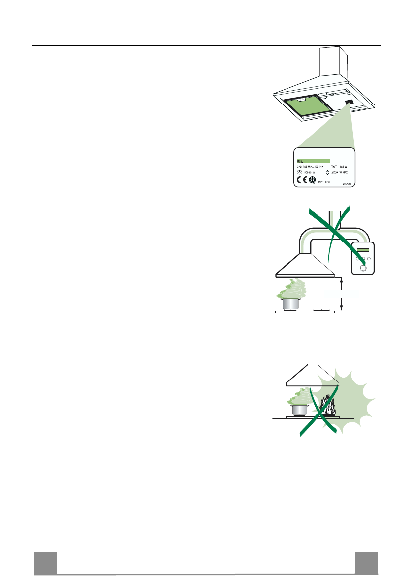
• The minimum safety distance between the cooker top and the extrac tor hood is 650 mm.
• Check that the mains voltage corresponds to that indicated on the
rating plate fixed to the inside of the hood.
• For Class I applianc es, c heck t hat th e domes tic po wer suppl y gua rantees adequate earthing.
Connect the extractor to the exhaust flue through a pipe of mi nimum
diameter 120 mm. The route of the flue must be as short as possible.
• Do not connect the extractor hood to exhaust ducts carryi ng combustion fumes (boilers, fireplaces, etc.).
• If the extractor is used in conjuncti on with non-electrical appliances
(e.g. gas burning appliances), a suffici ent degree of aeration must be
guaranteed in the room in order to prevent the backflow of exhaust
gas. The kitchen must have an opening communicating directl y with
the open air in order to guarantee the entry of clean air.
USE
• The extractor hood has been designe d ex cl usi vely for domesti c us e to
eliminate kitchen smells.
• Never use the hood for purposes other than for whi ch it has ben designed.
• Never leave high naked flames under the hood when it is in operation.
• Adjust the fl ame intensity to direct it onto the bottom of the pan only,
making sure that it does not engulf the sides.
• Deep fat fryers must be continuously monitored during use: overheated oil can burst into flames.
• Do not flambè under the range hood; risk of fire
• The hood should not be used by chil dren or persons not inst ructed in
its correct use.
MAINTENANCE
• Switch off or unplug the appliance from the mains supply before carrying out any maintenance work.
• Clean and/or replace the Filters after the specified time period.
• Clean the hood using a damp cloth and a neutral liquid detergent.
650 mm min.
Page 19
EN 119
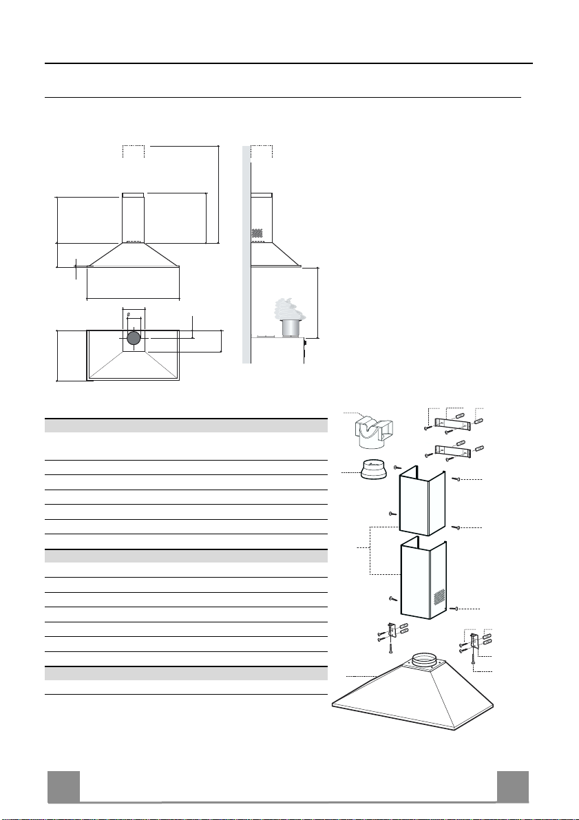
CHARACTERISTICS
560
240
18
598 - 698 - 898
210
150
490
100
Dimensions
max. 765
min. 560
650 min.
205
Components
Ref. Q.ty Product Components
1 1 Hood Body, complete with: Controls, Light, Blower,
Filters
2 1 Telescopic Chimney comprising:
2.1 1 Upper Section
2.2 1 Lower Section
9 1 Reducer Flange ø 15 0-120 mm
15 1 Air Outlet Connection
Ref. Q.ty Installat i on Comp o nent s
7.1 2 Hood Body Fixing Brackets
7.2.1 2 Upper Chimney Section Fixing Brackets
11 8 Wall Plugs
12a 8 Screws 4.2 x 44,4
12c 6 Screws 2.9 x 9.5
12d 2 Screws M4 x 25
Q.ty Documentation
1 Instruction Manual
15
9
2.1
2
2.2
1
12a 11
7.2.1
12c
12c
12c
12a 11
7.1
12d
Page 20
EN 220
INSTALLATION
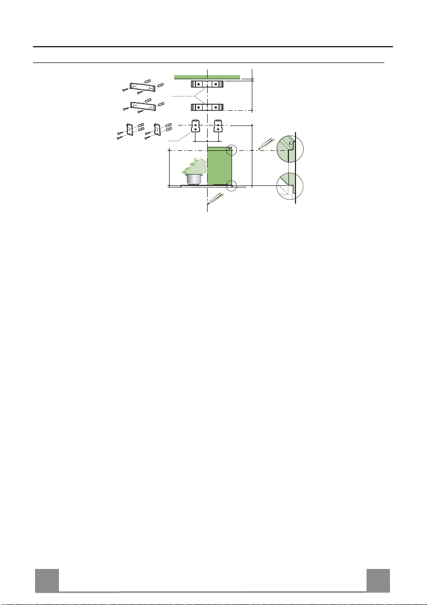
Wall drilling and bracket fixing
7.2.1
95
7.1
95
650 min.
Wall marking:
• Dra w a vertical line on the supporting wall up to the ceiling, or as high as practical, at the
centre of the area in which the hood will be installed.
• Draw a horizontal line at 650 mm above the hob for installation without the back panel, or at
height H (H=height of the visible part of the panel) for installation with the back panel.
• Place bracket 7.2.1 on the wall as shown about 1-2 mm from the ceiling or upper limit align-
ing the centre (notch) with the vertical reference lin e.
• Mark the wall at the centres of the holes in the bracket .
• P l ace br acket 7.2.1 on the wall as shown at X mm below the first bracket (X = height of the
upper chimney section supplied), aligning the centre (notch) with the vertical line.
• Mark the wall at the centr es of the holes in the bracket.
• P l ace bracket 7.1 as shown 95 mm from the vertical reference line and 210 mm above the
horizontal reference line.
• Mark the centres of the holes in the bracket.
• Repeat this operation on the other side.
1÷2
X
210
H
REAR PANEL (OPTIONAL)
The Rear Panel must be fitted before fixing the hood body and, if it is to be fixed at both top
and bottom, must be fitted at the correct height prior to installing the bases. As this operation is
rather complex, it should be carried out either by the kitchen installer or a qualified person
who knows the final dimensions of the units.
For fixing at the top only, proceed as follows:
• Rest the back panel on the b ase, in serting t he lower plat e bet ween the u pper surface an d th e
wall, centring it on the vertical reference line.
• Mark the centres of the two holes in the upper plat e.
• Drill ø 8 mm holes at all the centre points marked.
• Insert the wall plugs 11 in the holes.
• Fix the brackets u s ing the 12a screws (4,2 x 44,4) supplied.
• Fix the back panel (where present) using the 12a (4,2 x 44,4) screws supplied.
Page 21

EN 221
Mounting the hood body
7.1
12.d
15
• Screw the two screws 12d supplied onto the brackets 7.1.
• Hook the hood body onto the bracket 7.1, centring it around
the vertical line.
• Use the adjusting screws 12d underneath the hood to level the
hood body.
Connections
DUCTED VERSION AIR EXHAUST SYSTEM
When installing the ducted version, connect the hood to the
chimney using either a flexible or rigid pipe ø 150 or 120 mm,
the choice of which is left to the installer.
• To install a ø 120 mm air exhaust connection, insert the reducer flange 9 on the hood body outlet.
• Fix the pipe in position using sufficient pipe clamps (not supplied).
• Remove any activat ed charcoal filters.
ø 120ø 150
9
RECIRCULATION VERSION AIR OUTLET
• Push fit the air outlet fitting 15 onto the air outlet of the hood
body.
• Ensure that the activated charcoal filters have been inserted.
Page 22
EN 222
ELECTRICAL CONNECTION
• Connect the hood to the mains through a two-pole
switch having a contact gap of at least 3 mm.
• Remove the grease filters (see paragraph Maintenance) being sure that the connector of the feeding
cable is correctly inserted in the socket p laced on t he
side of the fan.
Flue assembly
Upper exhaust flue
• Slightly widen the two sides of the upper flue and
hook them behind the brackets 7.2.1, making sure
that they are well seated.
• Secure the sides to the brackets using the 4 screws
12c (2,9 x 9,5) supplied.
Lower ex haust flue
• Slightly widen the two sides of the flue and hook
them between the upper flue and the wall, making
sure that they are well seated.
• Fix the lower part laterally to the hood body using
the 2 screws 12c (2,9 x 9,5) supplied.
• Make sure that the air outlet connection is aligned
with the chimney outlets.
12c
2.2
2
12c
2.1
12c
Page 23
EN 223
USE
Control panel
3
2
1
0
1
0
M
L
L Light Switches the lighting system
on and off.
M Motor Switches the extractor motor
on and off.
V Speed Sets the operating speed of
the extractor:
1. Low speed, used for a
continuous and silent air
change in the presence of
light cooking vapour.
2. Medium speed, suitable
for most operating conditions given the optimum
treated air flow/noise
level ratio.
3. Maximum speed, used for
eliminating the highest
cooking vapour emission,
including long periods.
1
V
L
S
V1 V2 V3
L Light Switches the lighting system
on and off.
S Led Motor running led.
V1 Motor Switches the extractor motor
on and off at low speed.
Used to provide a continuous
and silent air change in th e
presence of light cooking
vapours.
V2 Speed Medium speed, suit able for
most operating conditions
given the optimum treat ed
air flow/noise level ratio.
V3 Speed Maximum speed, us ed for
eliminating the highest cooking vapour emission, including long periods.
Page 24

EN 224
MAINTENANCE
A
B
Grease filters
CLEANING META L SELF- SUPPO RTING GREASE FILTERS
• The filters must be cleaned every 2 months of operation, or
more frequently for particularly heavy usage, and can be
washed in a dishwasher.
• Remove the filters one at a time by pushing them towards
the back of the group and pulling down at the same time.
• Wash the filters, taking care not to bend them. Allow them
to dry before refitting.
• When refitting the filters, make sure that the handle is visible
on the outside.
Activated charcoal filter (Recirculation version)
These filters are not washable and cannot be regenerated, and
must be replaced approximatel y every 4 months of operati on, or
more frequently with heavy usage.
REPLACING THE ACTIVATED CHARCOAL FILTE R
• Remove the metal grease filters
• Remove the saturated activated charcoal filter as shown (A).
• Fit the new filters (B).
• Replace the metal grease filters.
Page 25

EN 225
Lighting
LIGHT REPLACEMENT
40 W incandescent light.
• Remove the metal grease filters.
• Unscrew the bulbs and replace them with new ones havin g the
same characteristics.
• Replace the metal grease filters.
Lighting
LIGHT REPLACEMENT
20 W halogen light.
• Remove the 2 screws fixing the Lighting support, and pull it
out of from the Hood.
• Extract the lamp from the Support.
• Replace with another of the same type, making sure that the
two pins are properly inserted in the lamp holder socket holes.
• Replace the Support, fixing it in place with the two screws removed as above.
Page 26

FR 226
CONSEILS ET SUGGESTIONS
INSTALLATION
• Le fabricant décline toute responsabilité en cas de dommage dû à
une installation non correcte ou non conforme aux règles de l’art.
• La distanc e minimale de sécurité ent re le plan de cuisson et la ho tte
doit être de 650 mm au moins.
• Vérifier que la tensi on du sec teu r c or respond à l a val eur qui fi gu re s ur
la plaquette apposée à l’intérieur de la hotte.
• Pour les Appareils appartenant à la Ière Classe, veiller à ce que la
mise à la terre de l’installation électrique domestique ait été effectuée
conformément aux normes en vigueur.
• Connecter la hotte à la sortie d’air aspiré à l’aide d’une tuyauterie
d’un diamètre égal ou supérieur à 120 mm. Le parcours de la
tuyauterie doit être le plus court possible.
• Eviter de connecter la hotte à des conduites d’évacuation de fumées
issues d’une combustion tel que (Chaudière, cheminée, etc…).
• Si vous utilisez des appareils qui ne fonctionnent pas à l’électricité
dans la pièce ou est installée la hotte (par exemple: des appareils
fonc tionnant au gaz), vous devez prévoir une aération suffisante du
milieu. Si la cuisine en est dépou rvue, pratiquez une ouverture qui
communique avec l’extérieur pour garantir l’infiltration de l’air pur.
UTILISATION
• La hotte a été c onçue exclusivement pour l’ usage domestique, dans
le but d’éliminer les odeurs de la cuisine.
• Ne jamais utiliser abusivement la hotte.
• Ne pas laiss er les flammes libres à forte intensité quand la hotte est
en service.
• Toujours régler les flammes de manière à éviter toute sortie latérale
de ces dernières par rapport au fond des marmites.
• Contrôler les friteuses lors de l’utilisation car l’huile surchauffée
pourrait s’enflammer.
• Ne pas préparer d’ aliments flambés sous la hotte de cuisine : risque
d’incendie
• La hotte ne doit pas être utilisée par des enfants ou des personnes ne
pouvant pas assurer une utilisation correcte.
ENTRETIEN
• Avant de procéder à toute opération d’entretien, retirer la hotte e n
retirant la fiche ou en actionnant l’interrupteur général.
• Effec tuer un entretien scrupuleux et en temps dû des Filtres , à la cadence conseillée.
• Pour le nettoyage des surfaces de la hotte, il suffit d’utiliser un chiffon
humide et détersif liquide neutre.
650 mm min.
Page 27

FR 227
CARACTERISTIQUES
560
240
18
598 - 698 - 898
210
150
490
min. 560
100
Encombrement
max. 765
650 min.
205
Composants
Réf. Q.té Composants de Produit
1 1 Corps Hotte équ ipé de: Comm andes, Lum ière, Grou pe
Ventilateur, Filtres
2 1 Cheminée Télescopique formée par :
2.1 1 Cheminée Supérieure
2.2 1 Cheminée Inférieure
9 1 Flasque de Réduction ø 150-12 0 mm
15 1 Raccord Sortie Air
Réf. Q.té Composants pour l’installation
7.1 2 Brides Fixation Corps Hotte
7.2.1 2 Brides Fixation Cheminée Supérieure
11 8 Chevilles
12a 8 Vis 4,2 x 44,4
12c 6 Vis 2,9 x 9,5
12d 2 Vis M4 x 25
Q.té Documentation
1 Manuel d’instructions
15
9
2.1
2
2.2
1
12a 11
7.2.1
12c
12c
12c
12a 11
7.1
12d
Page 28

FR 228
INSTALLATION
Perçage Paroi et Fixation Brides
1÷2
7.2.1
X
7.1
95
95
210
650 min.
H
Tracer sur la paroi:
• une ligne verticale allant jusqu’au plafond ou à la limite supérieure, au centre de la zone
prévue pour le montage de la hotte;
• une ligne horizontale à 650 mm min. au-dessus du plan de cuisson pour installation sans
embases: à la cote H (H=hau teur d e la partie en vue de l ’embase), en cas d ’inst allatio n avec
embase.
• Poser comme indiqué un e bride 7.2.1 sur la paroi à 1-2 mm du plafond ou de la limite supérieure, en alignant son centre (découpes) sur la ligne verticale de repère.
• Marquer les centres des trous rainurés de la bride.
• Poser comme indiqué la bride 7.2.1 à X mm sous la première bride (X = hauteur cheminée
supérieure fournie), en al ignant son centre (découpes) sur la lign e vert icale de repère.
• Marquer les centres des trous rainurés de la bride.
• Poser comme indiqué, la bride 7.1 à 95 mm de la ligne verticale de repère, et 210 mm audessus de la ligne horizontale de repère.
• Marquer les centres des trous de la bride.
• Répéter cette opération sur le côté opposé.
FIXATION EMBASE (SI FOURNIE)
L’Embase doit être montée avant d’installer le corps de la hotte et si l’on souhaite la fixer au
mur par lehaut ou par le bas, il est nécessaire de la monter à la juste hauteur avant de monter
les bases. Comme il s’agit d’une opération complexe, elle doit être confiée à l’installateur de la
cuisine ou à un p ersonnel compétent ayan t pris connaissance d e toutes les dimensi ons finales
des meubles.
En se limitant à la fixation supérieure, procéder comme suit :
• Poser l’embase sur la b ase en in séran t l’in tercalai re in férieur en tre le p lan sup érieur et la paroi, en le centrant par rapport à la ligne verticale de repère.
• Marquer les centres des deux trous de l’intercalaire supérieur.
• Percer de ø 8 mm tous les points marqués.
• Insérer les chevilles 11 dans les trous.
• Fixer les brides en utilisant les vis 12a (4,2 x 44,4) fournies.
• Si présente, fixer l’embase, en utilisant les vis 12a (4,2 x 44,4) fournies.
Page 29

FR 229
Montage Corps Hotte
7.1
12.d
15
• Visser sur les brides 7.1 les 2 vis 12d fournies.
• Accrocher le corps hotte aux brides 7.1, en le centrant sur la
ligne verticale.
• Agir sur les vis 12d, par le dessous de la hotte pour en niveler
le corps.
Branchements
SORTIE AIR VERSION ASPIRANTE
En cas d’installation en version aspirante, brancher la hotte à la
tuyauterie de sortie via un tube ri-gide ou flexible de ø 150 ou
120 mm, au choix de l’installateur.
• En cas de branchement avec un tube de ø120 mm, insérer le
flasque de réduction 9 sur la sortie du corps de la hotte.
• Fixer le tube par des colliers appropriés. Le matériau nécessaire n’est pas fourni.
• Retirer les éventuels filtres anti-odeur au charbon actif.
ø 120ø 150
9
SORTIE AIR VERSION FILTRANTE
• Appliquer par pression le raccord sortie air 15 sur
la sortie du corps de la hotte.
• S’assurer de la présence des filtres anti-odeur au
charbon actif.
Page 30

FR 330
BRANCHEMENT ELECTRIQUE
• Brancher la hotte sur le secteur en interpo sant un interrupteur bipolaire avec ou verture des contacts d’au
moins 3 mm.
• Enlever les filtres à graisse (voir § "Entretien") et
s'assurer que le connecteu r du câble d'alimentation
soit bien branché dans la prise du diffuseur.
Montage Cheminée
Cheminée supérieure
• Elargir légèrement les deux bords latéraux, et les accrocher derrière les brides 7.2.1 ; refermer jusqu’à la
butée.
• Fixer latéralement aux brides, à l’aide des 4 vis 12e
(2,9 x 9,5) fournies.
Cheminée inférieure
• Elargir légèrement les deux bords latéraux de la Cheminée et les accrocher entre la C heminée supérieure
et la paroi; refermer jusqu’à la butée.
• Fixer latéralement la partie inférieure aux bagues prévues à cet effet, à l’aide des 2 vis 12c fournies.
• S’assurer également qu’elles soient bien insérées
dans les raccord 15.
12c
2.2
2
12c
2.1
12c
Page 31

FR 331
UTILISATION
Tableau de commande
3
2
1
0
1
0
M
L
L Lumières Allume et éteint l’éclairage.
M Moteur Allume et éteint le moteur
aspiration.
V Vitesses Détermine les vitesses
d’exploitation ainsi subdivisées:
1. Vitesse minimale, pour
un rechange d’air permanent particulièreme nt silencieux en cas de faibles
vapeurs de cuisson.
2. Vitesse moyenne pour la
plupart des conditions
d’utilisation, étant donné
le rapport optimal entre
débit d’air traité et niveau
sonore.
3. Vitesse maximum, pour
faire face aux émissions
maximum de vapeur de
cuisson, même pendant
des temps prolongés.
1
V
L
S
V1 V2 V3
L Lumières Allume et éteint l’éclairage.
S Led Led allumage moteur.
V1 Moteur Met en marche et à l’arrêt le
moteur aspiration à vitesse
minimale, pour un rechange
d’air permanent particulièrement silencieux en cas de
faibles vapeurs de cuisson.
V2 Vitesse Vitesse moyenne pour la plu-
part des conditions
d’utilisation, étant donné le
rapport optimale entre débit
d’air traité et niveau so nore.
V3 Vitesse Vitesse maximum, pour faire
face aux émissions maximum de vapeur de cuisson,
même pendant des temps
prolongés.
Page 32

FR 332
ENTRETIEN
A
B
Filtres anti-graisse
NETTOYAGE FILTRES ANTI-GRAISSE METALLIQUES AUTOPORTEURS
• Lavables au lave-vaisselle, ils doivent être lavés environ tous
les 2 mois d’emploi ou plus fréquemment en cas d’emploi particulièrement intense.
• Retirer les filtres l’un aprés l’autre, en les poussant vers la partie arrière du groupe et en tirant simultanément vers le bas.
• Laver les filtres en évitant de les plier et les laisser sécher avant
de les remonter.
• Remonter les filtres en veillant à ce que la poignée reste vers la
partie visible externe
Filtre anti-odeur (Version filtrante)
Il ne sont pas lavables ni régénérables, il faut les remplacer au
moins tous les 4 mois d’emploi ou plus fréquemment en cas
d’emploi particulièrement intense.
REMPLACEMENT FILTRE AU CHARBON ACTIF
• Retirer les filtres anti-graisse métalliques.
• Retirer les filtres anti-odeur au charbon actif saturés, comme
indiqué (A).
• Monter les nouveaux filtres (B).
• Remonter le filtres anti-graisse métalliques.
Page 33

FR 333
Eclairage
REMPLACEMENT LAMPES
Lampes à incandescence de 40 W
• Retirer les filtres anti-graisse métalliques.
• Dévisser les lampes et les remplacer par de nouvelles avec le s
mêmes caractéristiques.
• Remonter les filtres anti-graisse métalliques.
Eclairage
REMPLACEMENT LAMPES
Lampe halogène de 20 W.
• Retirer les 2 Vis qui fixent le Support éclairage et ôter ce d ernier de la Hotte.
• Extraire la Lampe du Support.
• Re mplacer par un e nouvelle lampe possédant les mêmes caractéristiques, en veillant à ce que les deux fiches soient correctement insérées dans le logement de la Douille.
• Remonter le Support en le fixant à l’aide des deux Vis précédemment retirées.
Page 34

DE 334
EMPFEHLUNGEN UND HINWEISE
MONTAGE
• Der Hersteller ha ftet nicht für Schäden, die auf eine fehl erhafte und
unsachgemäße Montage zurückzuführen sind.
• Der minimale Sicherheitsabstand zwischen Kochmulde und Haube
muss 650 mm betragen.
• Prüfen, o b die Netzspannung mit dem Wert auf dem im H aubeninneren angebrachten Schild übereinstimmt.
• Bei Geräten d er Klasse I ist sicherzus tellen, dass die elektrisc he Anlage des Wohnhauses über eine vorschriftsmäßige Erdung verfügt.
• Das Anschlussrohr der Haube zur Luftaustrittsöffnung muss einen
Durchmesser von 120 mm oder darüber aufweisen. Der Rohrverl auf
muss so kurz wie möglich sein.
• Die Haube darf an keine Entlüftungs schächte anges chloss en werden,
in die Verbrennungsgase (Heizkessel, Kamine usw.) geleitet werden.
• Werden im Raum außer der Dunstabzugs haube andere, nicht elektrisch betriebene (z.B. gasbetri ebene) Geräte verwendet, muss für eine ausreichende Belüftung gesorgt werden. Sollte die Küche diesbezüglich nicht entsprechen, ist an ein er Aussenwand eine Öffn ung anzubringen, die Frischluftzufuhr gewährleistet.
BEDIENUNG
• Die Dunstabzugshaube ist ausschließlich zum Einsatz im privaten
Haushalt und zur Beseitigung von Küchengerüchen vorgesehen.
• Unsachgemäßer Einsatz der Haube ist zu unterlassen.
• Große Flammen bei eingeschalteter Haube niemals unbedeckt lassen.
• Die Intensivität der Flamme i st so zu reguliere n, dass s ie den Topfboden nicht überragt.
• Frittiergeräte müssen während des Gebrauchs stets beaufsichtigt
werden: überhitztes Öl kann sich entzünden.
• Keine flambierten Speisen unter der Abzugshaube zubereiten:
Brandgefahr.
• Die Dunstabzugshaube da rf vo n Kindern oder Pe rsonen, die hins ichtlich der Bedienung nicht unterwi esen wurden, keinesfalls verwendet
werden.
WARTUNG
• Bevor Wa rtungsarbeiten durchgef ührt werden, muss die Stromzufuhr
zur Haube unterbrochen werden, indem der Stecker gezogen oder
der Hauptschalter abgeschaltet wird.
• Bei der Filterwartung müssen die vom Hersteller empf ohlenen Zeiträume zum Austauschen der Filter genauestens eingehalten werden.
• Zur Reinigung der Haubenflächen Wir empfehlen ein feuchtes Tuch
und ein mildes Flüssigreinigungsmittel.
650 mm min.
Page 35

DE 335
CHARAKTERISTIKEN
560
240
18
598 - 698 - 898
210
150
490
min. 560
100
Platzbedarf
max. 765
650 min.
205
Komponenten
Pos. St. Produktkomponenten
1 1 Haubenkörper mit Schaltern, Beleuchtung, Gebläse-
gruppe, Filtern
2 1 Teleskopkamin bestehend aus:
2.1 1 oberer Kaminteil
2.2 1 unterer Kaminteil
9 1 Reduzierflansch ø 150-120 mm
15 1 Luftaustritt-Anschlussstück
Pos. St. Montagekomponenten
7.1 2 Befestigungsbügel Haubenkörper
7.2.1 2 Befestigungsbügel oberer Kaminteil
11 8 Dübel
12a 8 Schrauben 4,2 x 44,4
12c 6 Schrauben 2,9 x 9,5
12d 2 Schrauben M4 x 25
St. Dokumentation
1 Bedienungsanleitung
15
9
2.1
2
2.2
1
12a 11
7.2.1
12c
12c
12c
12a 11
7.1
12d
Page 36

DE 336
MONTAGE
Bohren der Befestigungslöcher und Fixieren der Befestigungsbügel
7.2.1
1÷2
X
7.1
95
95
210
650 min.
H
Nachstehende Linien an die Wand zeichnen:
• eine vertikale Linie bis zur Decke oder oberen Begrenzung, und zwar in der Mitte des Bereiches, in dem die Haube montiert werden soll;
• eine horizontale Linie: mit einem minimalen Abstand von 650 mm zur Kochfläche bei Montage ohne Rückwandpaneel; mit einem Abstand H (H= Höhe des sichtbaren Teils des
Rückwandpaneels) bei Montage mit Rückwandpaneel.
• Einen Bügel 7.2.1 zirka 1-2 mm unter der Decke oder oberen Begrenzung an die Wand legen und seinen Mittelpunkt (Einschnitte) auf die vertikale Bezugslinie ausrichten.
• Die Mitte der beiden Bügellöcher an der Wand markieren.
• Den zweiten Bügel 7.2.1 an die Wand legen, wobei ein Abstand X mm vom oberen Bügel
einzuhalten ist (X = Höhe des jeweiligen oberen Kaminteils); den Mittelpunkt (Einschnitte)
auf die vertikale Bezugslinie ausrichten.
• Die Mitte der Bügellöcher an der Wand markieren.
• Einen der beiden Bügel 7.1 95 mm von der vertikalen Bezugslinie und 210 mm oberhalb der
horizontalen Bezugslinie auflegen.
• Die Mittelpunkte der Bügelbohrungen an der Wand markieren.
• Gleichermaßen an der gegenüberliegenden Seite vorgehen.
RÜCKWANDPANEEL (OPTION)
Das Rückwandpaneel wird vor der Dunstabzugshaube montiert; falls es sowohl an der Oberwie auch Unterseite befestigt werden soll, muss es vor Montage der Unterschränke in korrekter
Höhe fixiert werden. Da es sich hierbei um einen komplexen Arbeitsschritt handelt, muss dieser Vorgang vom Kücheninstallateur bzw. auf jeden Fall von erfahrenem Personal durchgeführt werden, das die Endmaße der Küchenmöbel kennt.
Wird das Rückwandpaneel nur oben fixiert, ist wie nachstehend vorzugehen:
• Das Paneel auf den Unterschrank stellen und den unteren Rand zwischen Arbeitsfläche und
Wand schieben, wobei die Rückwand auf die vertikale Bezugslinie auszurichten ist.
• Die Bohrun gen an der oberen Kante kennzeichn en.
• Mit einem Bohrer ø 8 mm die markierten Punkte bohren.
• Die Dübel 11 in die Bohrungen einfügen.
• Die Bügel mit den mitgelieferten Schrauben 12a (4,2 x 44,4) fixieren.
• Falls ein Rückwandpaneel vorhanden ist, dieses mit den mitgelieferten Schrauben 12a (4,2 x
44,4) fixieren.
Page 37

DE 337
Montage des Haubenkörpers
7.1
12.d
15
• Bei den Bügeln 7.1 die 2 mitgelieferten Schrauben 12d ein-
schrauben.
• Den Haubenkörper bei den Haltebügeln 7.1 einhängen und auf
die vertikale Linie ausricht en.
• Mit Hilfe der Schrauben 12d vom Haubenunteren her den
Haubenkörper ausrichten.
Anschlüss in abluftversion
Bei Abluftbetrieb kann die Haube vom Installateur wahlweise
mittels Rohr oder Schlauch (ø 150 oder 120 mm) an die Außenrohrleitung angeschlossen werden.
• Bei Verwendung eines Anschlussrohres ø 120 den Reduzierflansch 9 am Haubenaustritt anbringen.
• Das Rohr mit geeigneten Rohrschellen fixieren. Das hierzu
erforderliche Material wird nicht mitgeliefert.
• Eventuell vorhandene Aktivkohlefilter entnehmen.
ø 120ø 150
9
ANSCHLUSS IN UMLUFTVERSION
• Das Anschlussstück 15 beim Luftaustritt des Haubenkörpers
eindrücken.
• Sicherstellen, dass der Aktivkohle-Geruchsfilter vorhanden ist.
Page 38

DE 338
ELEKTROANSCHLUSS
• Bei Anschluss der Haube an das Stromnetz muss ein
zweipoliger Schalter mit einem Öffnungsweg von
mindestens 3 mm zwischengeschaltet werden.
• Entfernen Sie die Fettfilter (s. Abschnitt „Wartung“)
und versichern Sie sich, daß die Kabelverbindung in
die Steckdose des Gebläses einwandfrei eingesteckt
wird.
Kaminmontage
Oberer Kaminteil
• Die beiden seitlichen Schenkel leicht auseinanderbiegen, hinter den Bügeln 7.2.1 einhängen und bis
zum Anschlag wieder schließen.
• Bei den Bügeln mit Hilfe der 4 mitgelieferten
Schrauben 12e (2,9 x 9,5) fixieren.
Unterer Kaminteil
• Die beiden seitlichen Schenkel des Kaminteils leicht
auseinanderbiegen, zwischen dem oberen Kaminteil
und der Wand einhängen und bis zum Anschlag wieder schließen.
• Den unteren Kaminteil an der Seite bei den entsprechenden Buchsen mit 2 der mitgelieferten Schrauben
12c fixieren.
• Sicherstellen, dass sie korrekt beim LuftaustrittAnschluss 15 eingerastet sind.
12c
2.2
2
12c
2.1
12c
Page 39

DE 339
BEDIENUNG
3
2
1
0
1
0
M
L
L Beleucht. Schaltet die Beleuchtung ein
und aus.
M Motor Schaltet den Gebläsemotor
ein und aus.
V Geschw. bestimmt die Gebl äsegech-
windigkeit und steuert folgende Geschwindigkeitsstufen:
1. geringste Gebläsestufe,
diese Stufe ist für einen
ständigen und besonders
leisen Luftaustausch bei
geringer Kochdunstentwicklung geeignet.
2. mittlere Gebläsestufe,
eignet sich aufgrund des
guten Verhältnisses zwischen Fördervolumen und
Geräuschentwicklung für
die meisten Anwendungssituationen.
3. höchste Gebläsestufe,
eignet sich für starke
Kochdunstentwicklung,
auch über längere Zeit
hin.
1
V
Bedienfeld
S
V1 V2 V3
L Beleucht. Schaltet die Beleuchtung ein
und aus.
S Led Betriebsanzeigelampe.
V1 Motor Schaltet den Gebläsemotor
mit minimaler Geschwindigkeit ein oder aus. Diese Stufe
ist für einen ständigen und
besonders leisen Luftaustausch bei geringer Kochdunstentwicklung geeignet.
V2 Geschw. Mittlere Gebläsestufe, eignet
sich aufgrund des guten Verhältnisses zwischen Fördervolumen und Geräuschentwicklung für die Meisten
Anwendungsstuationen.
V3 Geschw. Höchste Gebläsestufe, eignet
sich für starke Kochdunstentwicklung, auch über längere Zeit hin.
L
Page 40

DE 440
WARTUNG
A
B
Fettfilter
SELBSTTRAGENDER METALL FETTFILTER REINIGUNG
• Sie müssen nach 2-monatigem Betrieb bzw. bei starkem
Einsatz auch häufiger gereinigt werden, was im Geschirrspüler möglich ist.
• Die Filter nacheinander aushaken, indem sie auf die Rückseite der Gruppe geschoben und gleichzeitig nach unten gezogen werden.
• Die Filter reinigen (darauf achten, sie nicht zu verbiegen)
und vor der Remontage trocknen lassen.
• Bei der Remontage ist darauf zu achten, dass sich der Griff
auf der sichtbaren Außenseite befindet.
Geruchsfilter (Umluftversion)
Sie können weder gewaschen noch wiederverwendet werden und
sind alle 4 Betriebsmonate bzw. bei starkem Einsatz auch häufiger auszutauschen.
AUSTAUSCHEN DER AKTIVKOHLE FIL TE R
• Die Metallfettfilter entnehmen.
• Den gesättigten Aktivkohle-Geruchsfilter wie gezeigt entfernen (A).
• Die neuen Filter wie gezeigt montieren (B).
• Die Metallfettfilter wieder montieren.
• Die Kohlefilter können mit dem Hausmüll entsorgt werden.
Page 41

DE 441
Beleuchtung
AUSWECHSELN DER LAMPEN
Glühlampen 40W
• Die Metallfettfilter entfernen.
• Die Lampen ausschr auben und durch gleichwertige erset zen.
• Die Metallfettfilter wieder montieren.
Beleuchtung
Halogenlampe 20 W
• Vor dem Auswechseln der Lampen, die beiden Schrauben der
Lampenhalterung loesen und die Lampenhalterung aus der
Dunstabzugshaube ziehen.
• Die Lampe aus der Halteru ng nehmen.
• Die Lampe durch eine gleichwertige ersetzen und bei der Remontage darauf achten, daß die beiden Steckerstifte vorschriftsmäßig in die Lampenfassung eingeführt werden.
• Die Lampenhalterung wieder montieren, indem die beiden zuvor entfernten Schraub en wieder angezogen werden.
AUSWECHSELN DER LAMPEN
Page 42

NL 442
ADVIEZEN EN SUGGESTIES
INSTALLATIE
• De fabrikant aanvaardt geen enkele aansprakelijkheid voor schade
die voortkomt uit onjuiste of niet overeenkomsti g de regels der kuns t
uitgevoerde installaties.
• De minimale veiligheids afstand tusse n de kookpl aat en de was emkap
bedraagt 650 mm.
• Controleer of de netspanning correspondeert met de spanning die
aangegeven is op het plaatje aan de binnenkant van de wasemkap.
• Voor ap paraten van kl asse I dient u zic h ervan te verzekeren dat h et
elektriciteitsnet in uw huis over een goede aarding beschikt.
• Verbind de wasemkap met de luchtuitl aat door middel van een l eiding
met een diameter van 120 mm of groter. De leiding moet een zo kort
mogelijke route afleggen.
• Sluit de wasemkap niet aan op afvoerpijpen van rook die geproduceerd is door verbranding (verwarmingsketels, open haarden etc.).
• Als er in het vertrek zowel de wasemk ap als apparaten die niet op
elektriciteit werken (bijvoorbeeld gasapparaten) worden gebruikt,
moet ervoor worden gezo rgd dat het vertrek voldoe nde geventileerd
wordt. Indien de keuken geen gat in de buitenmuur heeft om de aan voer van schone lucht te garanderen, dient dit gemaakt te worden.
GEBRUIK
• De wasemkap is uitsluitend ontworpen voor huishoudelijk gebruik,
voor het elimineren van kookgeur en. Gebruik de kap nooit op oneigenlijke wijze.
• Laat geen hoog brandende branders onbedekt onder de wasemkap
terwijl deze in werking is.
• Regel de vlammen altijd zo dat ze niet l angs de pannen omhoogkomen.
• Controleer frituur pannen tijdens het gebruik: de overv erhitte olie zou
vlam kunnen vatten.
• Er mag niet onder de afzuigkap geflambeerd worden; brandgevaar
• De wasemkap mag niet gebruik t wor den door k inderen of doo r pe rsonen die niet in staat zijn de kap correct te gebruiken.
ONDERHOUD
• Alvorens onderhoudswerkzaamhede n uit te voeren, moet de wasemkap uitgeschakeld worden door de stekker ui t het s topcontac t te halen
of de hoofdschakelaar om te zetten.
• Voer het onderhoud van de filters altijd tijdig en nauwgezet uit,volgens
de aanbevolen intervallen.
• Om de oppervlakken van de kap sc hoon te maken is het voldoende
een vochtige doek en een neutraal reinigingsmiddel te gebruiken.
650 mm min.
Page 43

NL 443
EIGENSCHAPPEN
560
240
18
598 - 698 - 898
210
150
490
Buitenafmetingen
max. 765
min. 560
650 min.
100
205
Onderdelen
Ref. Productonderdelen
1 1 Wasemkap compleet met: bedieningen, licht, ventilat-
orgroep, fi lters
2 1 Telescopische sc houw bestaande uit:
2.1 1 Bovenstuk
2.2 1 Onderstuk
9 1 Reductieflens ø 150-120 mm
15 1 Verbindingsstuk luchtuitlaat
Ref. Installatieonderdelen
7.1 2 Bevestigingsbeugels wasemkap
7.2.1 2 Bevestigingsbeug els bovenstuk van de schouw
11 8 Pluggen
12a 8 Schroeven 4,2 x 44, 4
12c 6 Schroeven 2,9 x 9, 5
12d 2 Schroeven M4 x 25
Documentatie
1 Gebruiksaanwijzing
15
9
2.1
2
2.2
1
12a 11
7.2.1
12c
12c
12c
12a 11
7.1
12d
Page 44

NL 444
INSTALLATIE
Boren van gaten in de wand en bevestiging van de draagbeugels
7.2.1
1÷2
X
95
7.1
650 min.
95
210
H
Trek de volgende lijnen op de wand:
• een verticale lijn tot aan het plafond of tot aan de bovenlimiet, in het midden van de zone
waar u de wasemkap wilt installeren;
• een horizontale lijn op: 650 mm min. boven de kookplaat, voor installatie zonder muurplaat;
op hoogte H (hoogte van het zichtbare gedeelte van de muurplaat), voor installatie met
muurplaat.
• Plaats, zoal s aangege ven , d e b eugel 7.2.1 op 1-2 mm van het plafond of van de bovenlimiet,
en lijn het midden ervan (inkepingen) uit op de verticale referentielijn.
• Teken de middelpunten van de gaten in de beugel af.
• Plaats, zoals aangegeven , de beugel 7.2.1 op X mm onder de eerste beugel (X = hoogte bijgeleverde bovenstuk van de schouw), en lijn het midden ervan (inkepingen) uit op de verticale referentielijn.
• Teken de middelpunten van de gaten in de beugel af.
• Plaats, zoals aangegeven, de beugel 7.1 op 95 mm van de verticale referentielijn en 210 mm
boven de horizontale referentielijn.
• Teken de middelpunten van de gaten in de beugel af.
• Herhaal deze handeli ng aan de andere kant.
MUURPLAAT (OPTIONEEL)
De muurplaat moet gemonteerd worden voordat de wasemkap wordt gemonteerd en dient, als
men de plaat zowel aan de bovenkant als aan de onderkant aan de wand wil bevestigen, op de
juiste hoogte te worden aangebracht voordat de bases worden gemonteerd. Aangezien het hier
een gecompliceerde op eratie betreft, moeten deze werkzaamheden worden u itgevoerd do or de
installateur van de keuken, of door vakbekwaam personeel dat alle uiteindelijke afmetingen
van de meubels kent.
Voor bevestiging alleen aan de bovenkant, gaat u als volgt te werk:
• Plaats de plaat op de basis en schuif de onderste klep tussen het bovenvlak en de wand, en
centreer de plaat op de verticale referentielijn.
• Teken de middelpunten de gaten van de bovenklep af.
• Boor op de afgetekende punten gaten van ø 8 mm.
• Schuif de pluggen 11 in de gaten.
• Bevestig de beugels met behulp van de bijgeleverde schroeven 12a (4,2 x 44,4).
• Bevestig, indien aanwezig de muurplaat met behulp ven de bijgeleverde schroeven 12a (4,2
x 44,4).
Page 45

NL 445
Montage van de Wasemkap
7.1
12.d
15
• Schroef de 2 bijgeleverde schroeven 12d in de beugels 7.1.
• Haak de wasemkap aan de beugels 7.1 en centreer hem op de
verticale lijn.
• Draai van onder de kap aan de schroeven 12d om de wasem-
kap recht te hangen.
Aansluitingen
LUCHTUITLAAT AFZUIGVERSIE
Bij installatie in afzuigversie, moet u de wasemkap met de uitlaatleiding verbinden door middel van een starre of buigzame
leiding van ø 150 of 120 mm, naar keuze van de installateur.
• Voor verbinding met een leiding van ø120 mm, moet de reductieflens 9 op de uitlaat van de wasemkap worden aangebracht.
• Zet de leiding vast met geschikt leidingklemmen. Het benodigde materiaal wordt niet bij de wasemkap geleverd.
• Verwijder de eventuele geurfilters met actieve koolstof.
ø 120ø 150
9
LUCHTUITLAAT FILTERVERSIE
• Druk het luchtuitlaatverbindingstuk 15 met kracht op de luchtuitlaat van de wasemkap.
• Verzeker u ervan dat de geurfilters met actieve koolstof geïnstalleerd zijn.
Page 46

NL 446
ELEKTRISCHE AANSLUITING
• Sluit de wasemkap aan op de netspanning met een
tweepolige schakelaar ertussen met een opening tussen de contacten van tenminste 3 mm.
• Verwijder de vetfilters (zie par. "Onderhoud") en
verzeker u ervan dat de stekker van de voedingskabel
goed in de contactdoos van de afzuigkap is gestoken.
Montage van de schouw
Bovenstuk van de sc ho uw
• De twee zijplaten enigszins openen, ze vasthaken
achter de beugels 7.2.1 en ze weer zo ver mogelijk
sluiten.
• Aan de zijkant aan de beugel bevestigen met de 4
bijgeleverde schroeven 12c.
Onderstuk van de schouw
• De twee zijplaten van de schouw enigszins openen,
ze vasthaken tussen het bovenstuk van de schouw en
de wand en ze weer zo ver mogelij k sl uiten.
• Bevestig het onderstuk aan de zijkanten aan de wasemkap met 2 van de bijgeleverde schroeven 12c.
• Verzeker u ervan dat de uitlaat van het verbindingsstuk correspondeert met de mondstukken van de
schouw.
12c
2.2
2
12c
2.1
12c
Page 47

NL 447
GEBRUIK
Bedieningspaneel
3
2
1
0
1
0
M
L
L Lichten Hiermee schakelt u de erlich-
ting aan en uit.
M Motor Hiermee schakelt u de af-
zuigmotor aan en uit.
V Snelheid Instelling van de werkings-
snelheid:
1.Minimumsnelheid, gschikt
voor een continue en zeer
stille luchtverversing, als er
weinig kookdampen zijn.
2.Gemiddelde snelheid, ge-
schikt voor de meeste gebruiksomstandigheden, gezien de uitstekende verhouding tussen de hoeveelheid
behandelde lucht en het geluidsniveau.
3.Maximumsnelheid, ge-
schikt om de grootste kookdampen tegen te gaan, ook
voor langere tijd.
1
V
L
S
V1 V2 V3
L Lichten Hiermee schakelt u de ver-
lichting aan en uit.
S Led Led motorinschakeling.
V1 Motor Inschakeling en uitschake-
ling van de afzuigmotor op
minimumsnelheid, geschikt
voor een continue en zeer
stille luchtverversing, als er
weinig kookdampen zijn.
V2 Snelheid Gemiddelde snelheid, ge-
schikt voor de meeste gebruiksomstandigheden, gezien de uitstekende verhouding tussen de hoeveelheid
behandelde lucht en het geluidsniveau.
V3 Snelheid Maximumsnelheid, geschikt
om de grootste kookdampen
tegen te gaan, ook voor langere tijd.
Page 48

NL 448
ONDERHOUD
A
B
Vetfilters
REINIGING VAN DE ZELFDRAGENDE METALEN VETFILTERS
• De filters moeten eens in de 2 maanden of, bij bijzonder intensief gebruik, vaker gereinigd worden, en kunnen ook in de
vaatwasmachine worden gewassen .
• Verwijder de filters één voor één door ze naar de achterkant
van de groep te duwen en ze tegelijkertijd omlaag te trekken.
• Was de filters en vermijd hierbij ze te buigen, en laat ze drogen
alvorens ze terug te plaatsen.
• Plaats de vetfilters terug en let er hierbij op dat de handgreep
zichtbaar blijft.
Geurfilter (filterversie)
De filters kunnen niet gewassen en niet geregenereerd worden en
dienen bij gebruik van de kap tenminste eens in de 4 maanden of,
bij bijzonder intensief gebruik, vaker te worden vervangen.
VERVANGING FILTER MET ACTIEVE KOOLSTOF
• Verwijder de vetfilters.
• Verwijder de verzadigde geurfilters met actieve koolstof, zoals
aangegeven (A).
• Monteer de nieuwe filters (B).
• Plaats de vetfilters terug.
Page 49

NL 449
Verlichting
VERVANGING VAN DE LAMPEN
Gloeilampen va n 40 W
• Verwijder de metalen vetfilters.
• Schroef de lampen los en vervang ze door nieuwe lampen met
dezelfde eigenschappen.
• Plaats de metalen vetfilters terug.
Verlichting
VERVANGING VAN DE LAMPEN
Halogeenlamp van 20 W.
• Verwijder de 2 schroeven waarmee de lamphouder is bevestigd
en verwijder de houder uit de kap.
• Trek de lamp uit de houder.
• Vervang de lamp door een nieuwe lamp met dezelfde eigenschappen en let er hierbij op dat de twee pinnen correct in de
behuizing van de worden gestoken.
• Monteer de houder door hem te bevestigen met de twee eerder
verwijderde schroeven.
Page 50

ES 550
CONSEJOS Y SUGERENCIAS
INSTALACIÓN
• El fabricante declina cualquier responsabilidad debida a los daños
provocados por una instalación i ncorrecta o no conforme con las reglas.
• La distancia mínima de seguridad entre la encimera y la campana
debe ser de 650 mm.
• Comp robar que l a tensión de red c orresponda a la i ndicada en l a placa situada en el interior de la campana.
• Para los aparatos de 1ª clase as egurarse de que la instal ación eléctrica doméstica posea una toma de tierra eficaz.
• Conectar la campana a la salida del aire de aspiración mediante un
tubo de 120mm de diámetro c om o m ínimo. El rec orri do d el tubo deb e
ser lo más corto posible.
• No conecta r la campana a tubos d e descarga de humos pro ducidos
por combustión (calderas, chimeneas, etc.).
• En el caso que en la cocina se utilice de manera silmultánea la campana y otros aparatos no eléctricos (por ejemplo aparatos de gas),
debe existir un sistema de ventilac ión suficiente para tod o el ambiente. Si la cocina no posee un orificio que comunique con el exterior,
hay que realizarlo para garantizar el recambio del aire.
USO
• La c ampana ha sido concebi da exc lusiv amente para un uso d omésti co, para eliminar los olores de la cocina. No utilizarla de manera inadecuada.
• No dejar lla mas libres de fuert e intensidad mientras la campana esté
funcionando.
• Regular siempre las llamas de manera que éstas no s obresalgan lateralmente con respecto al fondo de las ollas.
• Controlar las freídoras durante s u uso: el aceite muy c aliente se puede inflamar.
• No preparar alimentos flambè deb ajo de la campana de la cocina;
peligro de incendio
• La campana no debe ser utilizada por niños o personas que no conozcan su uso correcto.
MANTENIMIENTO
• Antes de efectuar cualquier operaci ón de mantenimiento, desenchufar la campana de la red eléctrica o apagar el interruptor general.
• Efectuar un mantenimiento escrupuloso e inmediato de los filtros,
según los intervalos de tiempo aconsejados.
• Para limpiar las superficies de la campana es suficiente utilizar un
trapo mojado y detergente líquido neutro.
650 mm min.
Page 51

ES 551
CARACTERÍSTICAS
560
240
18
598 - 698 - 898
210
150
490
100
Dimensiones
max. 765
min. 560
650 min.
205
Componentes
Ref. Cant. Componentes del Producto
1 1 Cuerpo campana dotado con: mandos, luz, grupo de
ventilación, filtros.
2 1 Chimenea Telescópica formada por:
2.1 1 Chimenea Superior
2.2 1 Chimenea Inferior
9 1 Brida de reducción ø 150-120 mm
15 1 Racor salida aire
Ref. Cant. Componentes de Instalación
7.1 2 Bridas de fijación campana
7.2.1 2 Bridas de fijación c himenea superior
11 8 Tacoos
12a 8 Tornillos 4.2 x 44,4
12c 6 Tornillos 2.9 x 9.5
12d 2 Tornillos M4 x 25
Cant. Documentación
1 Manual de instrucciones
15
9
2.1
2
2.2
1
12a 11
7.2.1
12c
12c
12c
12a 11
7.1
12d
Page 52

ES 552
INSTALACIÓN
Taladrado pared y fijación de las bridas
1÷2
7.2.1
X
7.1
95
95
210
650 min.
H
Trazar en la pared:
• una línea vertical hasta el cielorraso o límite superior, al centro de la zona prevista para el
montaje de la campana;
• una línea horizontal a 650 mm mín. sobre el plano de cocción, para la instalación sin Fondo;
a la cota H (H = altura de la parte del Fon do a la vista), para instalación con Fondo.
• Apoyar como se indica la b rida 7.2.1 a 1-2 mm del cielo o del límite superior, alineando su
centro (muescas) con la línea vertical de referencia.
• Marcar los centros de los orificios de la brida.
• Apoyar como se indica la brida 7.2.1 a X mm debajo de la primera brida (X = altura de la
chimenea superior), alineand o su centro (muescas) con la línea vertical de referencia.
• Marcar los centros de los orificios de la brida.
• Apo yar como se indica la brida 7.1 a 95 mm de la línea vertical de referencia, y 210 mm
sobre la línea horizontal de referencia.
• Marcar los centros de los orificios de la brida.
• Repetir esta operación en la parte opuesta.
FONDO (OPCIONAL)
El fondo debe montarse antes de montar el cuerpo de la campana y, si se desea fijarlo a la pared tanto en la parte superi or co mo inferior , es n ecesario mont arlo a la altura co rrecta, an tes d e
montar las bases. Como esta operación es compleja debe efectuarla solamente el instalador de
la cocina o personal competen te que conozca todas las dimensio ens finales de los muebles.
Si nos limitamos sólo a la fijación superior, proceder de la siguiente manera:
• Apoyar el fondo sobre la base introduciendo la falda inferior entre el plano superior y la pared, centrándolo en la línea vertical de referencia.
• Marcar los centros de los dos orificios de la falda superior.
• Perforar ø 8 mm los puntos marcados.
• Introducir los tarugos 11 en los orificios.
• Fijar las bridas, usando los tornillos 12a (4,2 x 44,4) en dotación .
• Si existe, fijar el fondo, usando los tornillos 12a (4,2 x 44,4) en dotación.
Page 53

ES 553
Montaje del cuerpo de la campana
7.1
12.d
15
• Atornillar en las bridas 7.1, los 2 tornillos 12d (M4 x 25) suministrados en dotación.
• Enganchar el cuerpo de la campan a en las bridas 7.1, cent rándolo en la línea vertical.
• Operar en los tornillos 12d, desde abajo de la camp ana, para
nivelar el cuerpo de la campana.
Conexiones
SALIDA DEL AIRE VERSIÓN ASPIRANTE
Para la instalación de la versi ón asp irant e, co nect ar la ca mpana a l
tubo de salida mediante un tubo rígido o flexible de ø150 o 120
mm, a discreción del instalador.
• Para la conexión con el tubo de ø120 mm, introducir la brida de
reducción 9 en la salida del cuerpo de la campana.
• Fijar el tubo con abrazaderas adecuadas. Este material no se
proporciona en dotación.
• Quitar los filtros antiolor al carbón activo.
ø 120ø 150
9
SALIDA DEL AIRE VERSIÓN FILTRANTE
• Introduci r a presión el racor 15 en la salida del aire.
• Comprobar la presencia de los filtros antiolor de
carbón activo.
Page 54

ES 554
CONEXIÓN ELÉCTRICA
• Conectar la campana a la red d e alimen tación eléctrica instalando un interruptor bipolar con apertura de
los contactos de 3 mm como mínimo.
• Quitar los Filtros antigrasa y asegurase de que el conector del Cable de aco metida esté colocado correctamente en el enchufe del Aspirador.
Montaje de la chimenea
Chimenea superior
• Ensanchar ligeramente las dos faldas laterales, engancharlas detrás de las bridas 7.2.1 cerrarlas hasta
el tope.
• Fijar a los lados de las bridas con los 4 tornillos 12c
(2,9 x 9,5) en dotación
Chimenea inferior
• Ensanchar ligeramente las dos faldas laterales de la
chimenea, engancharlas entre l a chimenea superior
y la pared y cerrarlas hasta el top e.
• Fijar lateralmente la parte inferior en el cuerpo de la
campana, con los 2 to rnillos 12c (2,9 x 9, 5) en dotación.
• Asegurarse que la salida del racor 15 coincida con las
boquillas de la chimenea.
12c
2.2
2
12c
2.1
12c
Page 55

ES 555
USO
Tablero de mandos
3
2
1
0
1
0
M
L
L Luces Enciende y apa ga la instala-
ción de iluminación.
M Motor Enciende y apaga el motor
de aspiración.
V Velocidad Determina las velocidades
de ejercicio:
1. Velocidad mínima, indicada para un recambio de
aire continuo muy silencioso, en presencia de pocos
vapores de cocción.
2. Velocidad media, indicada para la mayor parte de
las condiciones de uso, gracias a la óptima relación entre caudal de aire tratado y
nivel de ruido.
3. Velocidad máxima, indicada para hacer frente a
grandes cantidades de vap or
de cocción, incluso para
tiempos prolongados.
1
V
L
S
V1 V2 V3
L Luces Enciende y apaga la inst ala-
ción de iluminación.
S Led Led de encendido motor.
V1 Motor Enciende y apaga el motor
de aspiración a velocidad
mínima, adecuada para un
recambio de aire continuo
particularmente silencioso,
cuando hay pocos vapores
de cocción.
V2 Velocidad Velocidad media, indicada
para la mayor parte de las
condiciones de uso, gracias
a la óptima relación entre
caudal de aire tratado y nivel de ruido.
V3 Velocidad Velocidad máxima, indicada
para hacer frente a grandes
cantidades de vapo r de cocción, incluso para tiempos
prolongados..
Page 56

ES 556
MANTENIMIENTO
A
B
Filtros antigrasa
LIMPIEZA DE LOS FILTROS ANTIGRASA METÁLICOS
• Se pueden lavar en el lavavajillas y requieren un lavado cada 2
meses aproximadamente o más a menudo si su uso es muy intenso.
• Quitar los filtros uno por vez, operando en los enganches correspondientes.
• Lavar los filtros evitando que se doblen y dejarlos secar antes
de volverlos a montar.
• Montar los filtros prestando atención en mantener la manija
hacia la parte visible exterior..
Filtros antiolor (Versión filtrante)
No se pueden lavar ni regenerar, se deben cambiar cada 4 meses
o más a menudo si su uso es muy intenso.
SUSTITUCIÓN DE LOS FILTROS DE CARBÓN ACTIVO
• Quitar los filtros antigrasa metálicos.
• Quitar los filtros antiolor de carbón activo saturado, de la manera indicada (A).
• Montar los nuevos filtros (B).
• Montar los filtros antigrasa metálicos.
Page 57

ES 557
Iluminación
SUSTITUCIÓN DE LAS LÁMPARAS
Lámparas incandescentes de 4 0 W
• Quitar los filtros antigrasa metálicos, o abrir la rejilla portafiltros.
• Destornillar las lámparas y sustituirlas con nuevas que tengan
las mismas características.
• Montar nuevamente los filtros antigrasa metálicos, o cerrar la
rejilla portafiltros.
Iluminación
SUSTITUCIÓN DE LAS BOMBILLAS
Lámparas halógenas de 20 W
• Quitar los dos tornillos que fijan el soporte.
• Extraer la lámpara desde el soporte.
• Susti tuirla con una nueva con l as mismas características, po niendo cuidado en insertar correctamente los dos enchufes en
el asiento del soporte.
• Montar nuevamente el soporte fijándolo con los dos tornillos
que se habían quitado precedentemente.
Page 58

PT 558
CONSELHOS E SUGESTÕES
INSTALAÇÃO
• O fabricante declina toda e qualquer responsabilidade pelos danos
decorrentes de uma instalação não correcta ou feita não em confo rmidade com as normas da boa técnica.
• A distância mínima de segur ança entre a placa de cozedura e o e xaustor deve ser de 650 mm.
• Verifique se a tensão da re de coincide com a indicada na plac a de
características aplicada no interior do exaustor.
• Para os aparelhos de Classe I
doméstica garanta uma descarga correcta à terra.
• Ligue o exaustor à saída do ar aspirado utilizando um tubo de diâmetro igual ou superior a 120 mm. O percurso do tubo deve ser o mais
breve possível.
• Não ligue o ex austor a tubos de descarga de fum aça produzida porcombustão (caldeiras, lareiras, etc...).
• Caso no mesmo local sejam utilizados quer o exaustor, quer aparelhos não accionados pela corrente e léctrica (por exemplo, aparelhos
alimentados a gás), será preciso providenciar uma ventilação suficiente do aposento. Se a cozinha não possuir uma abertura que
comunique com o exteri or, provi denc ie a sua real ização par a garan tir
a entrada de ar limpo.
USO
• O exaustor foi projectado para ser utilizado exclusivamente em
ambientes domésticos, sendo a sua final idade a de re duzir os odor es
de cozedura. Não utilize o aparelho de maneira imprópria.
• As chamas de forte intensidade não devem ficar descobertas
enquanto o exaustor estiver a funcionar.
• Regul e sempre as chamas d e maneira que não sobr essaiam do fundo das panelas.
• Mantenha as frigideiras s ob controlo durante o uso: o óleo excessivamente aquecido pode inflamar-se.
• No prepare alimentos flamejados sob o exaustor. Perigo de incêndio!
• O exaustor não deve ser utilizado por crianças ou por pessoas não
devidamente habilitadas à sua utilização correcta.
a
, certifique-se de que a instalação
650 mm min.
MANUTENÇÃO
• Antes de efectuar qualquer operação de manutenção, desligue o
exaustor tirando a ficha da tomada de corr ente ou desli gando o i nterruptor geral.
• Faça uma manutenção atenta e rápida dos filtros, respeitando os
intervalos aconselhados.
• Para limpar as superfícies do exaustor, é suficiente utilizar um pano
húmido e detergente líquido neutro.
Page 59

PT 559
CARACTERÍSTICAS
560
240
18
598 - 698 - 898
210
150
490
100
Dimensões
max. 765
min. 560
650 min.
205
Componentes
Ref. Qtd Componentes do produto
1 1 Corpo do exaustor equipado com: Comandos, ilumina-
ção, grupo do ventilador e filtros
2 1 Chaminé telescópica formada p or:
2.1 1 Chaminé superior
2.2 1 Chaminé inferior
9 1 Flange de redução ø 150-125 mm
15 1 Conexão da saída de ar
Ref. Qtd Componentes de instalação
7.1 2 Suportes de fixação da estrutura do exaus tor
7.2.1 2 Suportes de fixaçã o da chaminé superior
11 8 Buchas
12a 8 Parafusos 4,2 x 44, 4
12c 6 Parafusos 2,9 x 9, 5
12c 2 Parafusos M4 x 25
Qtd Documentação
1 Manual de Instruções
15
9
2.1
2
2.2
1
12a 11
7.2.1
12c
12c
12c
12a 11
7.1
12d
Page 60

PT 660
INSTALAÇÃO
Perfuração da parede e fixação dos suportes
7.2.1
7.1
95
95
650 min.
Marque na parede:
• uma linha vertical até ao tecto ou ao limite superior, no centro da zona prevista para a montagem do exaustor;
• uma linha horizontal a: 650 mm, no mínimo, aci ma da placa do fogão para in stalação sem
fundo; à altura H (H=altura da parte visível do fundo), para instalação com fundo.
• Apoie o suporte 7.2.1 como indicado, a 1-2 mm de distância do tecto ou do limite superior,
alinhando o seu centro (entalhes) sobre a linha de referência vertical.
• Marque os centros dos furos do suporte.
• Apoie o suporte 7.2.1 como indicado, X mm abaixo do primeiro suporte (X = altura da cha-
miné superior que acompanha o exaustor), alinhando o seu centro (entalhes) sobre a linha de
referência vertical.
• Marque os centros dos furos do suporte.
• Apoie o suporte 7.1 como indicado, a 95 mm de distância da linha de referência vertical e
210 mm acima da linha de referência horizontal .
• Marque os centros dos furos do suporte.
• Repita a operação do lado oposto.
FUNDO (ACESSÓRIO DE OPÇÃO)
O fundo deve ser montado antes da montagem do corpo do exaustor e, se o utilizador quiser
fixá-lo contra a parede, quer superiormente, quer inferiormente, será necessário montá-lo à
altura correcta, antes da mont agem das bases. Na medida em que se trata de uma operação
complexa, deverá ser feita e xclusivamente pelo instalado r da cozinha ou por pessoal co mpetente, que conheça todas as dimensões finais dos móveis.
Limitando-se apenas à fixação superior, proceda conforme indicado abaixo:
• Apoie o fundo em cima da base, introduzindo a folha inferior entre o plano superior e a parede, centrando-o sobre a linha de referência Vertical.
• Marque os centros dos dois furos da chapa superior.
• Com uma broca de Ø 8 mm fure os pontos marcados.
• Introdu za as buchas 11 nos furos.
• Fixe os suportes, utilizando os parafusos 12a (4,2 x 44,4) incluídos nos acessórios.
• Se disponível, fixe o fundo, utilizando os parafusos 12a (4,2 x 44,4) incluído s nos acessórios.
1÷2
X
210
H
Page 61

PT 661
Montagem da estrutura do exaustor
7.1
12.d
15
• Nos suportes 7.1, aperte os 2 parafusos 12d incluídos nos aces-
sórios.
• Fixe a estrutura do exaustor aos suportes 7.1, centrando-a
sobre a linha vertical.
• Opere com os parafusos 12d, trabalhando por baixo do exaustor, para nivelar a estrutura do exaustor.
Ligações
SAÍDA DO AR PARA A VERSÃO ASPIRANTE
Para a instalação na V ersão Aspirante, ligue o exausto r ao tubo
de saída utilizando um tubo rígido ou flexível de ø150 ou 120
mm; esta escolha deve ser feita pel o instalador.
• Para a l igação com um tubo de ø120 mm, instale a flange de
redução 9 na saída do corpo do exaustor.
• Fixe o tubo com braçadeiras de aperto adequad as. O material
necessário não é fornecido com o aparelh o.
• Tire os filtros anti-odor de carvão activo, se presentes..
ø 120ø 150
9
SAÍDA DO AR PARA A VERSÃO FILTRANTE
• Aplique a conexão de saída de ar 15 à pressão sobre a saída da
estrutura do exaustor.
• Assegure-se de que o filtro anti cheiros, de carvão activo, se
encontra presente.
Page 62

PT 662
LIGAÇÃO ELÉCTRICA
• Ligue o e xtractor à alimentação utilizando um interruptor de dois pólos com uma folga de contacto de
pelo menos 3 mm.
• Retire os filtros contra gordura (ver parágrafo da
Manutenção) certificando-se de que o conector do
cabo de alimentação está correctamente instalado na
tomada existente do lado do ventilador.
Montagem da chaminé
Chaminé superior
• Alargue ligeiramente as duas folhas laterais, prendaas atrás dos suportes 7.2.1 e volte a fechálas completamente.
• Fixe lateralmente aos suportes com os 4 parafusos
12c (2,9 x 6,5) fornecidos com o aparelho.
Chaminé inferior
• Alargue ligeiramente as d uas folhas laterais da chaminé, prenda-as entre a chaminé superior e a parede e
feche-as de novo completamente.
• Fixe lateralmente a parte inferior do corpo do exaustor com os 2 parafusos 12c (2,9 x 6,5) fornecidos
com o aparelho.
• Assegure-se de que a saída da conexão 15 está a
coincidir com as embocadu ras da chaminé .
12c
2.2
2
12c
2.1
12c
Page 63

PT 663
UTILIZAÇÃO
Quadro de comandos
3
2
1
0
1
0
M
L
L Luzes Liga e desliga a Ilumina-
ção
M Motor Liga e desliga o motor de
exaustão
V Velocidade Determina a velocidade
de funcionamento:
1.Velocidade mínima,
indicada para uma troca
contínua do ar muito
silenciosa, se os vapores
de cozedura forem poucos.
2. Velocidade média,
indicada para a maior parte das condições de uso
vista a excelente relação
entre o débito do ar trat ado e o nível de ruído.
3.Velocidade máxima,
indicada para enfrentar as
máximas emissões de
vapores de cozedura,
mesmo durante períodos
prolongados.
1
V
L
S
V1 V2 V3
L Luzes Liga e desliga a Iluminação
S Led Led de ligação do motor.
V1 Motor Liga e desliga o motor de
aspiração à velocidade
mínima. É a velocidade
indicada para troca de ar
contínua, muito silenciosa,
em caso de produção de
pouca quantidade de vapor
de cozedura.
V2 Velocidade Velocidade média, indicada
para a maior parte das condições de uso vist a a excelente relação entre o débi to
do ar tratado e o nível de
ruído.
V3 Velocidade Velocidade máxima, indi-
cada para enfrentar as
máximas emissões de vap ores de cozedura, mesmo
durante períodos prolongados.
Page 64

PT 664
MANUTENÇÃO
A
B
Filtros contra gordura
LIMPAR OS FILTROS METÁLICOS CONTRA GORDURA
• Os filtros deverão ser limpos de 2 em 2 meses de funcionamento,
ou mais frequentemente em situações de utilização extrema e
podem ser lavados na má quina de la va r louç a .
• Retire os filtros, um de cada vez, empurrando-os para trás e
puxando-os ao mesmo tempo.
• Lave os filtros, tendo cuidado para não os dobrar. Antes de os
instalar novamente, certifique-se de que ficam bem secos.
• Ao instalar novamente os filtros, certifique-se de que a pega fica
visível do exterior.
Filtro anti-odor (Versão Filtrante)
Não pode ser lavado e não é regenerável, devendo ser substituído
de 4 em 4 meses de utilização ou com maior frequência, se o aparelho for utilizado com muita intensidade.
SUBSTITUIÇÃO DO FILTRO DE CARVÃO ACTIVO
• Tire os filtros metálicos antigordura.
• Remova o filtro anti-odor de carvão activo saturado, conforme
indicado.(A)
• Monte o filtro novo prendendo-o na sua sede.(B)
• Reinstale os filtros metálicos antigordura.
Page 65

PT 665
Iluminação
SUBSTITUIÇÃO DAS LÂMPADAS
Lâmpadas incandescentes de 40 W
• Tire os filtros metálicos antigordura ou abra a grade portafiltros.
• Desatarraxe as lâmpadas e substitua-as por novas de características iguais.
• Reinstale os filtros metálicos antigordura ou feche a grade porta-filtros.
Iluminação
SUBSTITUIÇÃO DAS LÂMPADAS
Lâmpadas de halogéneo de 20 W
• Tire os 2 parafusos que fixam o suporte de iluminação e
extraia-o do exaustor.
• Extraia a lâmpada do suporte.
• Substitua-a por uma nova de características iguais lembrandose de introduzir correctamente os dois pinos na sede do suporte.
• Reinstale o suporte fixando-o com os dois parafusos tirados na
operação anterior.
Page 66

GR 666
ΣΥΜΒΟΥΛΕΣ ΚΑΙ ΣΥΣΤΑΣΕΙΣ
ΕΓΚΑΤΑΣΤΑΣΗ
• Ο κατασκευαστής δεν φέρει καµία ευθύνη για βλάβες που οφείλονται σε λανθασµένη εγκατάσταση ή στη µη τήρηση των κανόνων της τεχνικής.
• Η ελάχιστη απόσταση ασφαλείας µεταξύ της επιφάνειας των εστιών και του
απορροφητήρα πρέπει να είναι 650 mm.
• Βεβαιωθείτε ότι η τάση του δικτύου αντιστοιχεί στην τιµή που αναγράφεται
στην πινακίδα στο εσωτερικό του απορροφητήρα.
• Για συσκευές κλάσης I βεβαιωθείτε ότι η οικιακή ηλεκτρική εγκατάσταση εξασφαλίζει σωστή γείωση.
• Συνδέστε τον απορροφητήρα στον αγωγό απαγωγής χρησιµοποιώντας σω-
λήνα µε διάµετρο ίση ή µεγαλύτερη από 120 mm. Η διαδροµή του σωλήνα
πρέπει να είναι όσο το δυνατόν συντοµότερη.
• Μη συνδέετε το σωλήνα σε αγωγούς απαγωγής καπναερίων που παράγονται
από καύση (λέβητες, τζάκια κλπ.).
• Σε περίπτωση που στο δωµάτιο εκτός από τον απορροφητήρα χρησιµοποιούνται και συσκευές που δεν καταναλώνουν ηλεκτρική ενέργεια (π.χ. συσκευές καύσης αερίου), θα πρέπει να προβλέπεται επαρκής αερισµός του
χώρου. Εάν η κουζίνα δεν διαθέτει ανοίγµατα, δηµιουργήστε ένα άνοιγµα που
να επικοινωνεί µε το εξωτερικό για να εξασφαλίζεται η είσοδος καθαρού αέρα.
ΧΡΗΣΗ
• Ο απορροφητήρας έχει µελετηθεί αποκλειστικά για οικιακή χρήση και για την
απαγωγή των οσµών της κουζίνας.
• Μη χρησιµοποιείτε ποτέ για άλλες χρήσεις τον απορροφητήρα.
• Μην αφήνετε ελεύθερες φλόγες µεγάλης έντασης κάτω από τον απορροφητήρα όταν λειτουργεί.
• Ρυθµίζετε πάντα τις φλόγες έτσι ώστε να µην προεξέχουν πολύ από τον πάτο
των σκευών.
• Ελέγχετε τις φριτέζες όταν χρησιµοποιούνται: το καυτό λάδι µπορεί να πάρει
φωτιά.
• Μην µαγειρεύετε φαγητά φλαµπέ κάτω από τον απορροφητήρα της κουζίνας.
Υπάρχει κίνδυνος πυρκαγιάς.
• Ο απορροφητήρας δεν πρέπει να χρησιµοποιείται από παιδιά ή από άτοµα
που δεν γνωρίζουν τη σωστή χρήση του.
ΣΥΝΤΗΡΗΣΗ
• Πριν από οποιαδήποτε επέµβαση συντήρησης, αποσυνδέστε τον απορροφητήρα βγάζοντας το φις από την πρίζα ή γυρνώντας το γενικό διακόπτη.
• Η συντήρηση των φίλτρων πρέπει να εκτελείται σχολαστικά και έγκαιρα στα
ενδεδειγµένα χρονικά διαστήµατα.
• Για τον καθαρισµό των επιφανειών του απορροφητήρα αρκεί να χρησιµοποιήσετε ένα υγρό πανί και ουδέτερο υγρό απορρυπαντικό.
650 mm min.
Page 67

GR 667
ΧΑΡΑΚΤΗΡΙΣΤΙΚΑ
560
240
18
598 - 698 - 898
210
150
490
∆ιαστάσεις
max. 765
min. 560
650 min.
100
205
Εξαρτήµατα
Αναφ. Ποσ. Εξαρτήµατα της συσκευής
1 1 Σώµα απορροφητήρα µε: Χειριστήρια, Φωτισµό, Φίλ-
τρα
2 1 Τηλεσκοπική καµινάδα αποτελούµενη από:
2.1 1 Πάνω καµινάδα
2.2 1 Κάτω καµινάδα
9 1 Φλάντζα συστολής Φ 150-120 mm
15 1 Ρακόρ εξόδου αέρα
Αναφ. Ποσ. Εξαρτήµατα για την εγκατάσταση
7.1 2 Στηρίγµατα στερέωσης σώµατος απορροφητήρα
7.2.1 2 Στηρίγµατα στερέωσης πάνω καµινάδας
11 8 Ούπα
12a 8 Βίδες 4,2 x 44,4
12c 6 Βίδες 2,9 x 9,5
12d 2 Βίδες M4 x 25
Ποσ. Έντυπα
1 Εγχειρίδιο οδηγιών
15
9
2.1
2
2.2
1
12a 11
7.2.1
12c
12c
12c
12a 11
7.1
12d
Page 68

GR 668
ΕΓΚΑΤΑΣΤΑΣΗ
∆ιάτρηση τοίχου και στερέωση στηριγµάτων
7.2.1
95
7.1
95
650 min.
Χαράξτε στον τοίχο:
• µία κατακόρυφη γραµµή ως την οροφή ή έως το ανώτερο σηµείο, στο κέντρο της ζώνης που
προορίζεται για την εγκατάσταση του απορροφητήρα.
• µια οριζόντια γραµµή σε: ελάχιστη απόσταση 650 mm πάνω από την επιφάνεια των εστιών,
για εγκατάσταση χωρίς πλάτη, ύψος H (H = ύψος της εξωτερικής επιφάνειας της πλάτης)
για εγκατάσταση µε πλάτη.
• Τοποθετήστε το στήριγµα όπως στην εικ. 7.2.1 σε απόσταση 1-2 mm από την οροφή ή από
το ανώτερο σηµείο, ευθυγραµµίζοντας το κέντρο του (εγκοπές) µε την κατακόρυφη γραµµή
αναφοράς.
• Σηµειώστε τα κέντρα των οπών του στηρίγµατος.
• Τοποθετήστε το στήριγµα όπως στην εικ. 7.2.1 σε απόσταση X mm κάτω από το πρώτο
στήριγµα (X = ύψος πάνω καµινάδας του εξοπλισµού), ευθυγραµµίζοντας το κέντρο του (ε-
γκοπές) µε την κατακόρυφη γραµµή αναφοράς.
• Σηµειώστε τα κέντρα των οπών του στηρίγµατος.
• Στηρίξτε όπως στην εικόνα το στήριγµα 7.1 σε απόσταση 95 mm από την κατακόρυφη
γραµµή αναφοράς και σε απόσταση 210mm πάνω στην οριζόντια γραµµή αναφοράς.
• Σηµειώστε τα κέντρα των οπών του στηρίγµατος.
• Επαναλάβετε αυτή την ενέργεια από την αντίθετη πλευρά
ΠΛΑΤΗ (ΠΡΟΑΙΡΕΤΙΚΗ)
Η πλάτη πρέπει να τοποθετηθεί πριν τοποθετήσετε το σώµα του απορροφητήρα και, αν θέλετε
να την στερεώσετε πάνω και κάτω στον τοίχο, πρέπει να την τοποθετήσετε στο σωστό ύψος
πριν την τοποθέτηση των στηριγµάτων. Η ενέργεια αυτή είναι αρκετά περίπλοκη και πρέπει
να εκτελείται µόνο από τον εγκαταστάτη της κουζίνας ή από εξειδικευµένο προσωπικό που
γνωρίζει όλες τις τελικές διαστάσεις των επίπλων.
Για τη στήριξη µόνο στο πάνω µέρος, ενεργήστε ως εξής:
• Στηρίξτε την πλάτη στη βάση τοποθετώντας το κάτω χείλος µεταξύ πάνω επιφάνειας και
τοίχου και κεντράροντας την κατακόρυφη γραµµή αναφοράς.
• Σηµειώστε τα κέντρα των δύο οπών του πάνω χείλους.
• Ανοίξτε οπές Φ 8 mm στα σηµεία αυτά.
• Τοποθετήστε τα ούπα 11 στις οπές.
• Στερεώστε τα στηρίγµατα χρησιµοποιώντας τις βίδες 12a (4,2 x 44,4) του εξοπλισµού.
• Εάν υπάρχει, στερεώστε την πλάτη χρησιµοποιώντας τις βίδες 12a (4,2 x 44,4) του εξοπλι-
σµού.
1÷2
X
210
H
Page 69

GR 669
Τοποθέτηση σώµατος απορροφητήρα
7.1
12.d
15
• Βιδώστε πάνω στα στηρίγµατα 7.1, τις 2 βίδες 12d του εξοπλισµού.
• Στερεώστε το σώµα του απορροφητήρα στα στηρίγµατα 7.1,
κεντράροντας στην κατακόρυφη γραµµή.
• Ρυθµίστε τις βίδες 12d, από το κάτω µέρος του απορροφητήρα, για να αλφαδιάσετε το σώµα του απορροφητήρα.
Συνδέσεις
ΕΞΟ∆ΟΣ ΑΕΡΑ ΜΟΝΤΕΛΟΥ ΑΠΑΓΩΓΗΣ
Για την εγκατάσταση του µοντέλου απαγωγής, συνδέστε τον απορροφητήρα στο σωλήνα εξόδου µε έναν άκαµπτο ή εύκαµπτο
σωλήνα o150 ή 120 mm, η επιλογή του οποίου επαφίεται στον
εγκαταστάτη.
• Για σύνδεση µε σωλήνα o120 mm, τοποθετήστε τη φλάντζα
συστολής 9 στην έξοδο του σώµατος του απορροφητήρα.
• Στερεώστε το σωλήνα µε κατάλληλα κολάρα. Τα αναγκαίο
υλικό δεν διατίθεται µε τον εξοπλισµό.
• Αφαιρέστε τυχόν φίλτρο ενεργού άνθρακα.
ø 120ø 150
9
ΕΞΟ∆ΟΣ ΑΕΡΑ ΜΟΝΤΕΛΟΥ ΑΝΑΚΥΚΛΩΣΗΣ
• Τοποθετήστε πρεσαριστά το ρακόρ εξόδου αέρα 15 στην έξοδο του σώµατος του απορροφητήρα.
• Βεβαιωθείτε για την παρουσία του φίλτρου ενεργού άνθρακα.
Page 70

GR 770
ΗΛΕΚΤΡΙΚΗ ΣΥΝ∆ΕΣΗ
• Συνδέστε τον απορροφητήρα στο δίκτυο παρεµβάλλοντας διπολικό διακόπτη µε άνοιγµα επαφών του-
λάχιστον 3 mm.
• Βγάλτε τα φίλτρα για λίπη (βλ. παρ. “Συντήρηση”)
και βεβαιωθείτε ότι ο συνδετήρας του ηλεκτρικού
καλωδίου έχει συνδεθεί σωστά στην υποδοχή της
µονάδα αναρρόφησης
Τοποθέτηση καµινάδας
Πάνω καµινάδα
• Ανοίξτε ελαφρά τα δύο πλευρικά χείλη, συνδέστε τα
πίσω από τα στηρίγµατα 7.2.1 και κλείστε για να ασφαλίσουν.
• Βιδώστε στα πλευρά των στηριγµάτων µε τις 4 βίδες
12c (2,9 x 9,5) του εξοπλισµού.
Κάτω καµινάδα
• Ανοίξτε ελαφρά τα δύο πλευρικά χείλη της καµινάδας, τοποθετήστε τα µεταξύ πάνω καµινάδας και τοίχου και κλείστε τα για να ασφαλίσουν.
• Στερεώστε από τα πλευρά το κάτω µέρος στους δακτυλίους µε τις 2 βίδες 12c (2,9 x 9,5) του εξοπλισµού.
• Βεβαιωθείτε επίσης ότι έχουν προσαρµόσει σωστά
στο ρακόρ 15.
12c
2.2
2
12c
2.1
12c
Page 71

GR 771
ΧΡΗΣΗ
Πίνακας χειριστηρίων
3
2
1
0
1
0
M
L
L Φωτισµός Ανάβει και σβήνει το
φως.
M Μοτέρ Ανάβει και σβήνει το µο-
τέρ αναρρόφησης.
V Ταχύτητα Επιλέγει την ταχύτητα
λειτουργίας:
1.Ελάχιστη ταχύτητα, κατάλληλη για ιδιαίτερα αθόρυβη και συνεχή εναλλαγή του αέρα, µε λίγους
ατµούς από το µαγείρεµα.
2.Μέση ταχύτητα, κατάλληλη για την πλειοψηφία
των συνθηκών χρήσης, µε
άριστη σχέση παροχής
επεξεργασµένου αέρα και
στάθµης θορύβου.
3.Μέγιστη ταχύτητα, κατάλληλη για µεγάλη παραγωγή ατµών από το µαγείρεµα, ακόµη και για
µεγάλο χρονικό διάστηµα.
1
V
L
S
V1 V2 V3
L Φωτισµός Ανάβει και σβήνει το φως.
S Led Led λειτουργίας µοτέρ.
V1 Μοτέρ Ανάβει και σβήνει το µοτέρ.
Αναρρόφηση µε ελάχιστη
ταχύτητα, κατάλληλη για ιδιαίτερα αθόρυβη και συνεχή εναλλαγή του αέρα, µε
λίγους ατµούς από το µαγείρεµα.
V2 Ταχύτητα Μέση ταχύτητα, κατάλληλη
για την πλειοψηφία των
συνθηκών χρήσης, µε άρι-
στη σχέση παροχής επεξεργασµένου αέρα και στάθµης
θορύβου.
V3 Ταχύτητα Μέγιστη ταχύτητα, κατάλ-
ληλη για µεγάλη παραγ ωγή
ατµών από το µαγείρεµα,
ακόµη και για µεγάλο χρονικό διάστηµα.
Page 72

GR 772
ΣΥΝΤΗΡΗΣΗ
A
B
Φίλτρα για λίπη
ΚΑΘΑΡΙΣΜΟΣ ΜΕΤΑΛΛΙΚΩΝ ΦΙΛΤΡΩΝ ΓΙΑ ΛΙΠΗ
• Μπορούν να πλυθούν στο πλυντήριο πιάτων και απαιτούν καθαρισµό τουλάχιστον κάθε 2 µήνες χρήσης ή συχνότερα σε
περίπτωση ιδιαίτερα συχνής χρήσης.
• Αφαιρείτε τα φίλτρα ένα τη φορά, επεµβαίνοντας στους ειδικούς γάντζους.
• Πλύνετε τα φίλτρα χωρίς να τα στραβώσετε και αφήστε τα να
στεγνώσουν πριν τα τοποθετήσετε στη θέ ση τους.
• Τοποθετήστε τα έτσι ώστε η λαβή να παραµείνει προς το εξωτερικό µέρος.
Φίλτρο ενεργού άνθρακα (Μοντέλο ανακύκλωσης)
∆εν µπορούν να πλυθούν και να αναγεννηθούν και πρέπει να αντικαθίστανται τουλάχιστον κάθε 4 µήνες χρήσης ή συχνότερα
σε περίπτωση ιδιαίτερα συχνής χρήσης.
ΑΝΤΙΚΑΤΑΣΤΑΣΗ ΦΙΛΤΡΟΥ ΕΝΕΡΓΟΥ ΑΝΘΡΑΚΑ
• Βγάλτε τα µεταλλικά φίλτρα για λίπη.
• Βγάλτε τα κορεσµένα φίλτρα ενεργού άνθρακα όπως στο σχέδιο (A).
• Τοποθετήστε τα νέα φίλτρα όπως στο σχέδιο (B).
• Τοποθετήστε τα µεταλλικά φίλτρα για λίπη.
Page 73

GR 773
Φωτισµός
ΑΝΤΙΚΑΤΑΣΤΑΣΗ ΛΑΜΠΤΗΡΩΝ
Λαµπτήρες πυρακτώσεως των 40 W.
• Βγάλτε τα µεταλλικά φίλτρα για λίπη.
• Ξεβιδώστε τους λαµπτήρες και αντικαταστήστε τους µε νέους
ίδιων χαρακτηριστικών.
• Τοποθετήστε τα µεταλλικά φίλτρα για λίπη.
Φωτισµός
ΑΝΤΙΚΑΤΑΣΤΑΣΗ ΛΑΜΠΤΗΡΩΝ
Λαµπτήρες αλογόνου των 20 W
• Βγάλτε τις 2 βίδες που στερεώνουν τη βάση φωτισµού και
βγάλτε την από τον απορροφητήρα.
• Βγάλτε το λαµπτήρα από τη βάση.
• Αντικαταστήστε τον µε νέο λαµπτήρα ίδιων χαρακτηριστικών,
έτσι ώστε να προσαρµόσουν σωστά τα δύο βύσµατα στις υποδοχές της βάσης.
• Τοποθετήστε τη βάση και στερεώστε την µε τις δύο βίδες που
αφαιρέσατε.
Page 74

Page 75

Page 76

Dir. 89/336/CEE
73/23/CEE
93/68/CEE
Il sim bolo sul prodotto o sulla confezione indica che il prodotto non deve essere considerato come un normale rifiuto domestico, ma deve essere
portato nel punto di raccolta appropriato per il riciclaggio di apparecchiature elettriche ed elettroniche. Provvedendo a smaltire questo prodotto in modo
appropriato, si contribuisce a evitare potenziali conseguenze negative per l’ambiente e per la salute, che potrebbero derivare da uno smaltime n to in a deguato del prodotto. Per informazioni più dettagliate sul riciclaggio di questo prodotto, contattare l’ufficio comunale, il servizio locale di smaltimento rifiuti o
il negozio in cui è stato acquistato il prodotto.
The symbol
on the product or on its packaging indicates that this product may not be treated as household waste. Instead it shall be handed over
to the applicable collection point for the recycling of electrical and electronic equipment. By ensuring this product is disposed of correctly, you will help
prevent potential negative consequences for the environment and human health, which could otherwise be caused by inappropriate waste handling of
this product. For more detailed information about recycling of this product, please contact your local city office, your household waste disposal service or
the shop where you purchased the product.
Le symbol e
sur le produit ou son emballage indique que ce produit ne peut être traité comme déchet ménager. Il doit plutôt être remis au point de
ramassage concer né, se cha rg e ant du re cycla ge du m a tériel éle ctriqu e et éle ctronique. En vous assurant que ce produ i t est éliminé correctement, vous
favorisez la prévention des conséquences négatives pour l’environnement et la santé humaine qui, sinon, seraient le résultat d’un traitement inapproprié
des déchets de ce produ it. Pour obten ir plus de détails sur le recyclage de ce produit, veuillez pre ndre co nta ct ave c le b urea u municipal de votre région,
votre service d’élimination des déchets ménagers ou le magasin où vous avez acheté le produit.
Das Symbol
auf dem Produkt oder seiner Verpackung weist darauf hin, dass dieses Produkt nicht als normaler Haushaltsabfall zu behandeln ist,
sondern an einem Sammelpunkt für das Recycling von elektrischen und elektronischen Geräten abgegeben werden muss. Durch Ihren Beitrag zum
korrekten Entsorgen dieses Produkts schützen Sie die Umwelt und die Gesundheit Ihrer Mitmenschen. Umwelt und Gesundheit werden durch falsches
Entsorgen gefährdet. Weitere Informationen über das Recycling dieses Produkts erhalten Sie von Ihrem Rathaus, Ihrer Müllabfuhr oder dem Geschäft, in
dem Sie das Produkt gekauft haben.
Het symbool
op het product of op de verpakking wijst erop dat dit product niet als huishoudafval mag worden behandeld. Het moet echter naar
een plaats worden gebracht waar elektrische en elektronische apparatuur wordt gerecycled. Als u ervoor zorgt dat dit product op de corr e cte man i er
wordt verwijderd, voorkomt u mogelijk voor mens en milieu negatieve gevolgen die zich zouden kunnen voordoen in geval van verkeerde afvalbehandeling. Voor meer details in verband m e t het recyclen van dit product, neemt u he t best con ta ct op m e t de gemeentelijke instanties, het bedrijf of de dienst
belast met de verwijdering van huishoudafval of de winkel waar u het product hebt gekocht.
El símbolo
se debe entregar al punto de recolección de equipos eléctricos y electrónicos para reciclaje. Al asegurarse de que este producto se deseche correcta-
en el producto o en su embalaje indica que este producto no se puede tratar como desperdicios normales del hogar. Este producto
mente, usted ayudará a evitar posibles consecuencias negativas para el ambiente y la salud pública, lo cual podría ocurrir si este producto no se manipula de forma adecuada. Para obtener información más detallada sobre el reciclaje de este producto, póngase en contacto con la administración de su
ciudad, con su servicio de desechos del hogar o con la tienda donde compró el producto.
O símbolo
centro de recolha selectiva para a reciclagem de equipamento eléctrico e electrónico. Ao garantir uma eliminação adequada deste produto, irá ajudar a
no produto ou na embalagem indica que este produto não pode ser tratado como lixo doméstico. Em vez disso, deve ser entregue ao
evitar eventuais consequências negativas para o meio ambiente e para a saúde pública, que, de outra forma, poderiam ser provocadas por um tratamento incorrecto do produto. Para obter informações mais pormenorizadas sobre a reciclagem deste produto, contacte os serviços municipalizados
locais, o centro de recolha selectiva da sua área de residência ou o estabelecimento onde adquiriu o produto.
Το σύµβολο
Αντιθέτως θα πρέπει να παραδίδεται στο κατάλλη λο σηµείο συλλογής για την ανακύκλωση ηλεκτρικού και ηλεκτρονικού εξοπλισµού. Εξασφαλίζοντας
στο προϊόν ή επάνω στη συ σκευασ ία το υ υποδεικνύει ότι δεν πρέπει να µ εταχειρίζεστε το προϊόν αυτό ως οικιακό απόρριµµα .
ότι το προϊόν αυτό διατίθεται σωστά, συµβά λλετε στην αποτροπή ενδεχόµενων αρνητικών συνεπειών για το περιβάλλον και την ανθρώπινη υγεία, οι
οποίες θα µπορούσαν διαφορετικά να προκληθούν από ακατάλληλο χειρισµό απόρριψη ς του προϊόντος αυτού. Για λεπτοµερέστερες πληροφορίες
σχετικά µε την ανακύκλωση του προϊόντος αυτού, επικο ινωνή στε µ ε το δηµαρχείο της περιοχής σας, την τοπική σας υπηρεσία αποκοµιδής οικιακών
απορριµµάτων ή µ ε το κατάστηµα όπου αγοράσατε το προϊόν.
4329653_ver8
 Loading...