

Page 1

Cooker hood
Hotte de cuisine
Dunstabzugshaube
Cappa
Dampkap
ZHC 511-513-514
713-714
INSTALLATION, USE AND MAINTENANCE HANDBOOK
MANUEL D’INSTRUCTIONS POUR L’INSTALLATION, L’EMPLOI ET L’ENTRETIEN
HANDBUCH FÜR INSTALLATION, BEDIENUNG UND WARTUNG
MANUALE DI INSTALLAZIONE, USO E MANUTENZIONE
INSTRUCTIES VOOR MONTAGE, GEBRUIK EN ONDERHOUD
Page 2

English .................................................... pag. 3
Français .................................................... pag. 7
Deutsch .................................................... pag. 11
Italiano .................................................... pag. 15
Nederlands .................................................... pag. 19
2
Page 3
Part 1 - INSTALLATION INSTRUCTIONS
1 - GENERAL INFORMATION
This canopy hood is designed to be fitted into cabinets or chimney cooker hoods, placed above
a hotplate. It can be used either in the extraction mode (ducted to the outside) or in the recirculation
mode (internal recycling).
Before starting the installation, consideration should be given to the difficulties to be found
during installation. The installation work must be undertaken by a qualified and competent
person in conformity to the rules concerning the evacuation of contaminated air.
The manufacturer disclaims all liability for any damage or injury caused as a result of not
following the instructions for installation contained in the following text.
2 - SAFETY WARNINGS
2.1 - When used in the extraction mode, the cooker hood ducting must not be connected to a flue
which is used for exhausting fumes from appliances supplied with energy other than electric,
such as a central heating flue or water heating flue.
2.2 - Before connecting to the mains supply ensure that the mains voltage corresponds with the
voltage on the rating plate inside the hood.
2.3 - Connect the cooker hood to the mains via a bipolar switch which has 3mm clearance
between the contacts.
2.4 - The appliance must be earthed.
2.5 - When installed, the hood must be positioned at least 65 cm above the hotplate.
2.6 - Never do flambé cooking under this cooker hood.
2.7 - Never leave frying pans unattended during use as overheated fat and oil may catch fire.
2.8 - Before carrying out any kind of maintenance or cleaning, disconnect the hood from the
mains supply.
2.9 - If the room where the cooker hood is to be used contains a fuel burning appliance such as
a central heating boiler then this must be of the room sealed or balanced flue type. If other
types of flue or appliance are fitted, ensure that there is an adequate supply of air into the
room. When the cooker hood is used in conjunction with appliances supplied with energy
other than electric, the negative pressure in the room must not exceed 0,04 mbar to prevent
fumes being drawn back into the room by the cooker hood.
3 - INSTALLATION
The following scheme has to be observed:
3.1 - Installation of the built-in group
3.2 - Set the hood for recirculation or evacuation
3.3 - Connect the hood to the mains supply and ensure that it works properly
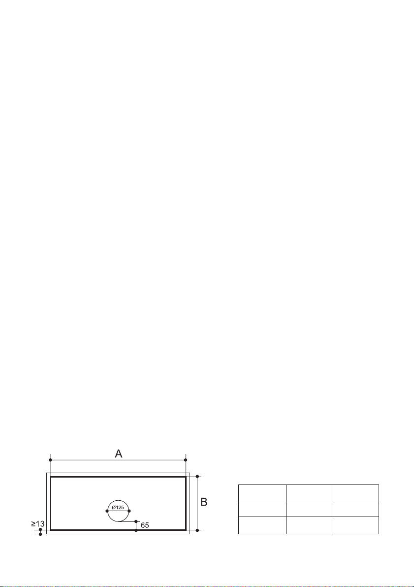
Cooker Hood
Dimensions
520 mm
700 mm
Side A
497 mm
677 mm
3
Side B
259 mm
259 mm
Page 4

3.1- Installation of the fitted group
1 - Make a rectangular opening in the base of the overhead cupboard or hood, leaving a minimum
of 13 mm from the outer edges according to the dimensions indicated in the table.
2 - Drill a hole into the upper side of the cabinet in accordance with the dimensions of the duct used
for both the evacuation and recirculation mode.
3 - Dismantle the ducting support (version with grill or version with filters), pulling the two pommels
A (fig. 1) simultaneously:
a)Fixing frame with screws:
Fix the fitted group to the hood or cupboard, using the self-threading screws (No. 8) provided
with the accessories (fig. 2).
b)Rapid fixing with side supports:
The device B is set up to deal with a panel thickness of from 15 mm to 30 mm. Insert the
group into the opening until the two devices B connect. Lock the adjustment screw C until the
fitted group adheres tightly to the surface (fig. 2).
4 - Close the ducting support by pushing and connecting the two pommels A (fig. 3).
3.2- Ducting or recirculation fitting
1 - Ducting fitting:
a)The hood can be ducted to the outside using either a rigid or a flexible Ø 100 or 120 mm
duct to be fixed with suitable clamps, not provided (fig. 2).
b)If the hood is provided with the charcoal filters fitted, the filters should be removed
(see par.3.2 part 2).
2 - Recirculation fitting:
a)When used in the recirculation mode, the charcoal filters must be fitted into the cooker hood
(see par. 3.2 part 2).
b)The air is recirculated into the kitchen through the opening located on the upper side of the
cabinet or of the hood (fig. 3).
3.3- Electrical connection and working test
1 - The safety measures 2.2, 2.3 and 2.4 of paragraph 2 are to be strictly observed.
2 - Once the electrical connection has been completed, check that the worktop illumination, motor
and speeds work properly.
Part 2 - USE AND MAINTENANCE
INSTRUCTIONS
1 - SAFETY WARNINGS
It is most important that all the warnings shown in paragraph 2 of the Installation
Instructions are strictly observed.
Moreover, special attention must be paid to the following warnings during the use and
maintenance of the cooker hood:
1.1 - The grease filters and the charcoal filters should be cleaned or replaced as recommended
by the manufacturer or more frequently if the hood is used consistently (more than 4 hours
per day).
1.2 - When using a gas hob in connection with the cooker hood never leave the burners of the
hob uncovered while the hood is in use or when the pans have been removed. Switch off
the gas before removing the pan or for just short periods and never leave the hob unattended.
1.3 - Always ensure that the appliance is kept at the correct intensity to prevent the flame from
4
Page 5

licking round from the bottom of the pan; this will save energy and will avoid a dangerous
concentration of heat.
1.4 - Always ensure that the appliance is used in accordance with the manufacturer’s instructions
for the removal of contaminated odours during cooking.
2 - USE
Control panel
The cooker hood can be operated as follows:
LIGHT SWITCH L = controls the worktop illumination;
MOTOR SWITCH M = controls the power to the motor and the fan speed:
Position 1 = low speed, should be selected when simmering or using only one pan: the
Position 2 = medium speed, should be selected for normal cooking. This speed offers the
Position 3 = top speed, should be selected when frying or cooking food with strong odours,
noise level is kept to the minimum.
best ratio between air capacity and noise level.
even for a long period.
3 - MAINTENANCE
Regular maintenance and cleaning will ensure good performance and reliability, while extending
the working life of the hood. Special attentions should be paid to the grease filters and to the
charcoal filters when the hood is used in the recirculation mode.
3.1- Metal grease filters
1 - Cleaning
The metal grease filter should be cleaned every two months with normal usage and can be
cleaned in a dishwasher or by hand using mild detergent or liquid soap.
2 - Replacement
The metal filters are easily removed, one at a time, applying a slight pressure towards the rear
of the hood while pulling downwards (fig. 6).
ATTENTION: There could be a possible fire hazard if the filters are not replaced according
to these instructions.
3.2- Synthetic filters
1 - This filter cannot be washed and should be replaced every two months. If the filter is provid ed
with a saturation indicator, replace when the violet color of the dots which are visible from the
outside is spread over the whole surface of the filter.
2 - Replacement:
a)Remove the ducting grill, referring to paragraph 3.1.3. on installation.
b)After having taken off the ducting grill, remove the filter stops (1). Replace the grease filter
(2) (fig. 7).
c)Close the ducting grill up again.
3.3- Grease Filters (metal panels)
1 - Cleaning
The metal grease filter should be cleaned every two months with normal usage and can be
cleaned in a dishwasher or by hand using mild detergent or liquid soap.
2 - Replacement:
a)Remove the ducting grill, referring to paragraph 3.1.3. on installation.
b)After dismantling the ducting grill, remove the filter stops (1). Wash the metal panels (2)
(fig. 7).
c)Close the ducting grill up again.
ATTENTION: There could be a possible fire hazard if the filters are not replaced according
to these instructions.
5
Page 6

3.4- Charcoal filters
1 - Functioning
In the recycling mode the charcoal filters absorb smell and odours. The charcoal filter cannot
be washed or regenerated and should be replaced every 2 months or more frequently if the hood
is used consistently.
2 - Replacement:
a)Remove the ducting grill, referring to paragraph 3.1.3. on installation.
b)Replace the active charcoal filter (fig. 8).
3.5- Lighting
This is provided by 2 40W bulbs.
1 - If the bulbs are not working, remove the support of the ducting grill and check that they are
properly screwed into place.
2 - If the bulbs are broken they must be replaced using new bulbs of the same voltage and power
(fig. 9).
3 - Close the ducting support again.
3.6- Cleaning
When cleaning the hood:
- Never use a wet cloth or sponge, or running water.
- Never use thinners or products containing alcohol, as they might damage the paintwork.
- Never use abrasive cleaning materials, in particular when cleaning stainless steel surfaces.
It is recommended to use a damp cloth and mild liquid household cleaner.
6
Page 7

1ère Partie - INSTRUCTIONS POUR
L’INSTALLATION
1 - GENERALITES
Cette hotte est destinée à être installée à l'intérieur d'un meuble ou d'une hotte cheminée, au
dessus d'un plan de cuisson.
Elle peut être utilisée en version évacuation (raccordement extérieur) ou recyclage (recyclage
interne).
A cause de la complexité de l’appareil il est préférable que l’installation soit effectuée par
un spécialiste tout en respectant les prescriptions des autorités concernant l’évacuation de
l’air.
La responsabilité du producteur ne saurait être engagée pour tout incident ou accident
provoqué par une installation défectueuse.
2 - CONSEILS CONCERNANT LA SECURITE
2.1 - N’utilisez jamais pour le raccordement une cheminée servant de conduit de fumée
(chaudières, cheminées, etc...)
2.2 - Vérifiez que la tension du secteur soit identique aux valeurs indiquées sur la plaquette
signalétique figurant à l’intérieur de la hotte.
2.3 - Reliez la hotte au réseau en interposant un interrupteur bipolaire avec ouverture des
contacts de 3 mm au moins.
2.4 - Assurez-vous que l’installation électrique de votre logement ait une mise à la terre correcte.
2.5 - La distance de sûreté minimum entre le plan de cuisson et la hotte est de 65 cm.
2.6 - Il est interdit de faire flamber des préparations sous la hotte.
2.7 - Lorsque des fritures sont effectuées sous la hotte en fonctionnement, elles doivent faire
l’objet d’une surveillance permanente: l’huile surchauffée pourrait s’enflammer.
2.8 - Avant d’effectuer le nettoyage ou l’entretien de la hotte, débranchez l’appareil ou agissez
sur l’interrupteur omnipolaire de votre installation.
2.9 - Une ventilation convenable de la pièce doit être prévue si une hotte de cuisine et des
appareils alimentés par une énergie autre que l’énergie électrique évacuent les fumées
simultanément. Une utilisation sans dangers est possible si la dépression maximum qui se
crée dans la pièce est inférieure à 0,04 mbar, ce que évite un retour des gaz de décharge
dans la pièce.
3 - INSTALLATION
Respectez le schéma suivant:
3.1 - Montage du groupe filtrant
3.2 - Connexion évacuation ou recyclage
3.3 - Raccordement électrique et contrôle fonctionnel
7
Dimensions
de la Hotte
520 mm
700 mm
Bord A
497 mm
677 mm
Bord B
259 mm
259 mm
Page 8

3.1- Installation du groupe à encastrer
1 - Effectuer une ouverture rectangulaire à la base du meuble haut ou de la hotte en laissant un
espace minimum de 13 mm à partir des bords externes selon les dimensions indiquées dans le
tableau.
2 - Percez un trou selon les dimensions du tuyau utilisé, à l'endroit prévu pour la sortie de l'air, soit
pour la version évacuation, que pour la version recyclage.
3 - Démonter le support d’aspiration (version avec grille ou version avec filtres), en tirant
simultanément les deux poignées A (fig. 1).
Fixation de la partie externe avec des vis;
Fixer le groupe à encastrer à la hotte ou au meuble haut en utilisant les vis autotaraudeuses (8)
fournies avec les accessoires (fig. 2).
Fixation rapide avec des supports latéraux;
Le dispositif B est prédisposé pour une excursion allant de 15 à 30 mm d’épaisseur panneau.
Introduire le groupe dans l’ouverture jusqu’à accrocher les deux dispositifs B. Serrer les vis de
réglage C jusqu’à ce que le groupe à encastrer adhère complètement au plan (fig. 2).
4 - Refermer le support d’aspiration en poussant et en accrochant les deux poignées A (fig. 3).
3.2- Connexion évacuation ou recyclage
1 - Connexion évacuation:
a)La hotte peut être branchée à un conduit extérieur à travers un tuyau rigide ou flexible de
Ø 100 ou 120 mm, à fixer avec des colliers pas fournis (fig. 2).
b)Retirez les éventuels filtres à charbon actif qui ne doivent pas être installés dans la hotte en
version évacuation (voir paragraphe 3.3 partie 2ème).
2 - Connexion recyclage:
a)Ajoutez les éventuels filtres à charbon actif à l’intérieur du corps de hotte (voir paragraphe 3.2
partie 2ème).
b)L’air filtré est evacué dans la pièce à travers une ouverture placée sur la partie supérieure de
l’armoire ou de la hotte (fig. 3).
3.3- Raccordement électrique et contrôle fonctionnel
1 - Il est nécessaire de respecter scrupuleusement les conseils 2.2, 2.3 et 2.4 du paragraphe 2
concernant la sécurité.
2 - Le raccordement électrique effectué, vérifiez le bon fonctionnement de l’éclairage, du moteur et
du changement des vitesses d’aspiration.
2ème partie - INSTRUCTIONS POUR
L’UTILISATION ET L'ENTRETIEN
1 - CONSEILS CONCERNANT LA SECURITE
Il est absolument nécessaire de respecter tous les avertissements du paragraphe 2 de la
1ère partie - Instructions pour l’installation.
En outre, il est très important de faire attention, lors de l’utilisation et de l’entretien, aux
avertissements suivants:
1.1 - Effectuez un scrupuleux et régulier entretien des filtres à graisses et à charbon actif, selon
les intervalles conseillées par le fabricant, ou plus souvent, pour une utilisation
particulièrement intense (plus de 4 heures par jour.)
1.2 - Ne laissez jamais des flammes libres à forte intensité sous la hotte en fonctionnement: en
retirant les marmites, éteignez la flamme ou du moins, pour de courtes périodes et sous
surveillance, tenez-la au minimum.
1.3 - Réglez toujours la flamme de façon à éviter une fuite latérale de la même par rapport au
fond des marmites: vous économisez de l’énergie et vous évitez de dangereuses concentrations
8
Page 9

de chaleur.
1.4 - N’utilisez jamais incorrectement votre appareil, qui est destiné uniquement à abattre les
odeurs dans la cuisine.
2 - UTILISATION
Groupe des commandes
Le schéma des commandes est le suivant (fig. 4):
TOUCHE LUMIERE L = mise en fonctionnement et arrêt de l’éclairage;
TOUCHE MOTEUR M = mise en marche et arrêt du moteur et choix de la vitesse d’aspiration:
1 = Vitesse minimum: pour ventiler la pièce, particulièrement silencieuse, pour les plats
émettant peu de vapeurs.
2 = Vitesse moyenne: en conditions normales, étant donné le rapport optimal entre la capacité
de dépuration et le niveau de bruit.
3 = Vitesse maximum: en cas de forte concentration d’odeurs et de vapeurs, même pour de
longues périodes.
3 - ENTRETIEN
Un entretien régulier de votre hotte est la garantie d’un bon fonctionnement et d’un bon rendement.
Des attentions particulières sont à adresser aux filtres à graisses métalliques et, pour les seules
hottes filtrantes, aux filtres à charbon actif.
3.1- Filtre à graisses métallique
1 - Nettoyage
Laver ces filtres avec un produit détergent du commerce au maximum tous les deux mois; grâce
à leur dimension compacte vous pouvez également les laver dans votre lave-vaisselle.
2 - Démontage des filtres
Enlevez un filtre à la fois en poussant vers l'arrère et en tirant en même temps vers le bas
(fig. 6).
3.2- Filtre à graisses synthétique
1 - Nettoyage
Ce filtre ne peut être lavé; il est indispensable de le changer tous les deux mois. Si le filtre est
équipé de points violets, témoins de saturation, sur toute sa surface et visibles à travers la grille,
il doit être changé lorsque les points s'étalent jusqu'à couvrir toute la surface du filtre.
2 - Remplacement:
a)Enlever la grille d’aspiration en se référant au paragraphe installation 3.1.3.
b)Après avoir démonté la grille d’aspiration, enlever les bloque-filtres (1).
Remplacer le filtre antigraisse (2) (fig. 7).
c)Refermer la grille d’aspiration.
3.3- Filtres antigraisse (panneaux métalliques)
1 - Nettoyage
Laver ces filtres avec un produit détergent du commerce au maximum tous les deux mois; grâce
à leur dimension compacte vous pouvez également les laver dans votre lave-vaisselle.
2 - Remplacement:
a)Enlever la grille d’aspiration en se référant au paragraphe installation 3.1.3.
b)Après avoir démonté la grille d’aspiration, enlever les bloque-filtres (1).
Laver les panneaux métalliques (2) (fig. 7).
c)Refermer la grille d’aspiration.
ATTENTION: Afin d’éviter des risques d’incendie provoqués par une accumulation de
graisse dans les filtres, il est nécessaire de respecter les conseils d’entretien et de
remplacement.
9
Page 10

3.4- Filtres à charbon actif
1 - Fonctionnement
Le filtre à charbon actif à la capacité de retinir les odeurs jusqu'à saturation. Il n'est pas lavable
et ne peut être régénéré; par conséquent il doit être changé tous les 4 mois ou plus souvent pour
une utilisation particulièrement lourde.
2 - Remplacement:
a)Enlever le support d’aspiration en se référant au paragraphe installation 3.1.3.
b)Remplacer les filtres au charbon actif (fig. 8).
3.5- Eclairage
Il est constitué de deux ampoules à 40 W.
1 - Si les ampoules ne fonctionnent pas, enlever le support ou la grille d’aspiration et contrôler
qu’elles soient bien vissées.
2 - Si les ampoules sont brûlées, elles doivent être remplacées avec d’autres ayant le même voltage
et la même puissance (fig. 9).
3 - Refermer le support d’aspiration.
3.6- Nettoyage
Pour le nettoyage normal de la hotte:
- Ne pas utiliser de chiffons ou d'éponges mouillés, ni de jets d'eau.
- Ne pas utiliser de diluants ou d'alcools, susceptibles de rendre opaques les surfaces vernies.
- Ne pas utiliser de substances abrasives, en particulier sur les surfaces en inox.
Il est conseillé d'utiliser un chiffon humide et un détergent liquide neutre.
10
Page 11

1
2
Page 12

3
4
Page 13

5
6
7
Page 14

8
9
 Loading...