

Operating
instructions
Gas hob
ZGS 688
IL

2

Thank you for selecting our appliance
We wish you lots of enjoyment with your new appliance and we hope that you will consider our
brand again when purchasing household appliances.
Please read this user manual carefully and keep it throughout the product life cycle as a reference
document. The user manual should be passed on to any future owner of the appliance.
3
Contents
For the User
Important Safety Information ....................................................................................................... 5
Description of the Hob ................................................................................................................. 7
When the hob is first installed ..................................................................................................... 8
Operation .................................................................................................................................... 8
Using the hob correctly.............................................................................................................. 10
Cleaning and Maintenance ......................................................................................................... 11
Something Not Working? ..........................................................................................................13
For the Installer
Technical data ........................................................................................................................... 14
Installation ................................................................................................................................. 15
Gas Connection ........................................................................................................................ 15
Building In ................................................................................................................................. 15
Fitting the hob to the worktop .................................................................................................... 17
Electrical Connection................................................................................................................. 18
Commissioning .......................................................................................................................... 19
Technical Maintenance .............................................................................................................. 19
Guide to Use the instructions
The following symbols will be found in the text to guide you throughout the Instructions:
Safety Instructions
Step by step instructions for an operation
!
Hints and Tips
Environmental information
It is very important that this instruction book should be kept safely for future consultation. If the
appliance should be sold or given to another person, please ensure that the booklet goes
together with it, so that the new owner can know of the functions of the machine and also be
aware of the warnings.
These instructions are only for the countries stated by the symbol printed on the front cover of
this instruction book.
4
English
Important safety information
This warnings has been given for the safety of you and others. We therefore ask you to carefully
read the procedures of installing and using this cooker.
Installation
" The work of installation must be carried out by
competent and qualified installers according
to the regulations in force.
• Any modifications to the domestic electrical
mains which may be necessary for the
installation of the appliance should be carried
out only by competent personnel.
During Operation
• This appliance has been designed for non
professional purpose in private houses only. It
is meant to cook edible foodstuff only and
must not be used for any other purposes.
• It is dangerous to alter the specification in any
way.
• For hygiene and safety reasons, this
appliance should be kept clean at all times. A
build-up of fats or other foodstuff could result
in a fire.
• Under no circumstances should you attempt
to repair the appliance yourself. Repairs
carried out by unexperienced persons may
cause injury or serious malfunctioning. Refer
to your local Service Centre. Always insist on
genuine spare parts.
• Ensure that all control knobs are in the OFF
position when not in use.
• Should you connect any electrical tool to a
plug near this cooking appliance, ensure that
electric cables are not in contact with it and
keep them far enough from the heated parts of
this appliance.
• If the appliance is out of order, disconnect it
from the electric supply.
Child Safety
• This appliance has been designed to be
operated by adults and children under
supervision. Young children must not be
allowed to tamper with the controls or play
near or with the oven.
• This appliance is not intended for use by
children or other persons whose physical,
sensory or mental capabilities or lack of
experience and knowledge prevents them
from using the appliance safely without
supervision or instruction by a responsible
person to ensure that they can use the
appliance safely.
• Accessible parts of this appliance may
become hot when it is in use. Children should
be kept away until it has cooled.
About Installation, Cleaning and
Manteinance
" It is mandatory that all operations required for
the installation are carried out by a qualified or
competent person, in accordance with existing
rules and regulations.
• Disconnect the appliance from the electrical
supply, before carrying out any cleaning or
manteinance work.
• Ensure a good ventilation around the
appliance. A poor air supply could cause lack
of oxygen.
• Ensure that the gas supply complies with the
gas type stated on the identification label,
placed near the gas supply pipe.
• This appliance is not connected to a
combustion products evacuation device. It
must be installed and connected in
accordance with current installation
5
regulations. Particular attention shall be given
to the relevant requirements regarding
ventilation.
• The use of a gas cooking appliance results
in the production of heat and moisture in
the room in which it is installed. Ensure
that the kitchen is well ventilated: keep
natural ventilation holes open or install a
mechanical ventilation device
(mechanical extractor hood).
• Prolonged intensive use of the appliance
may call for additional ventilation, for
example opening of a window, or more
effective ventilation, for example
increasing the level of mechanical
ventilation where present.
• Once you removed all packaging from the
appliance, ensure that it is not damaged and
the electric cable is in perfect conditions.
Otherwise, contact your dealer before
proceeding with the installation.
• The manufacturer disclaims any
responsability should all the safety
measures not be carried out.
Service
• Under no circumstances should you attempt
to repair the appliance yourself. Repairs
carried out by unexperienced persons may
cause injury or serious malfunctioning. Refer
to your local Service Centre. Always insist on
genuine spare parts.
The symbol on the product or
on its packaging indicates that this product may
not be treated as household waste. Instead it shall
be handed over to the applicable collection point
for the recycling of electrical and electronic
equipment. By ensuring this product is disposed of
correctly, you will help prevent potential negative
consequences for the environment and human
health, which could otherwise be caused by
inappropriate waste handling of this product. For
more detailed information about recycling of this
product, please contact your local city office, your
household waste disposal service or the shop
where you purchased the product.
Environmental Information
" After installation, please dispose of the
packaging with due regard to safety and the
environment.
• When disposing of an old appliance, make
it unusable, by cutting off the cable.
6
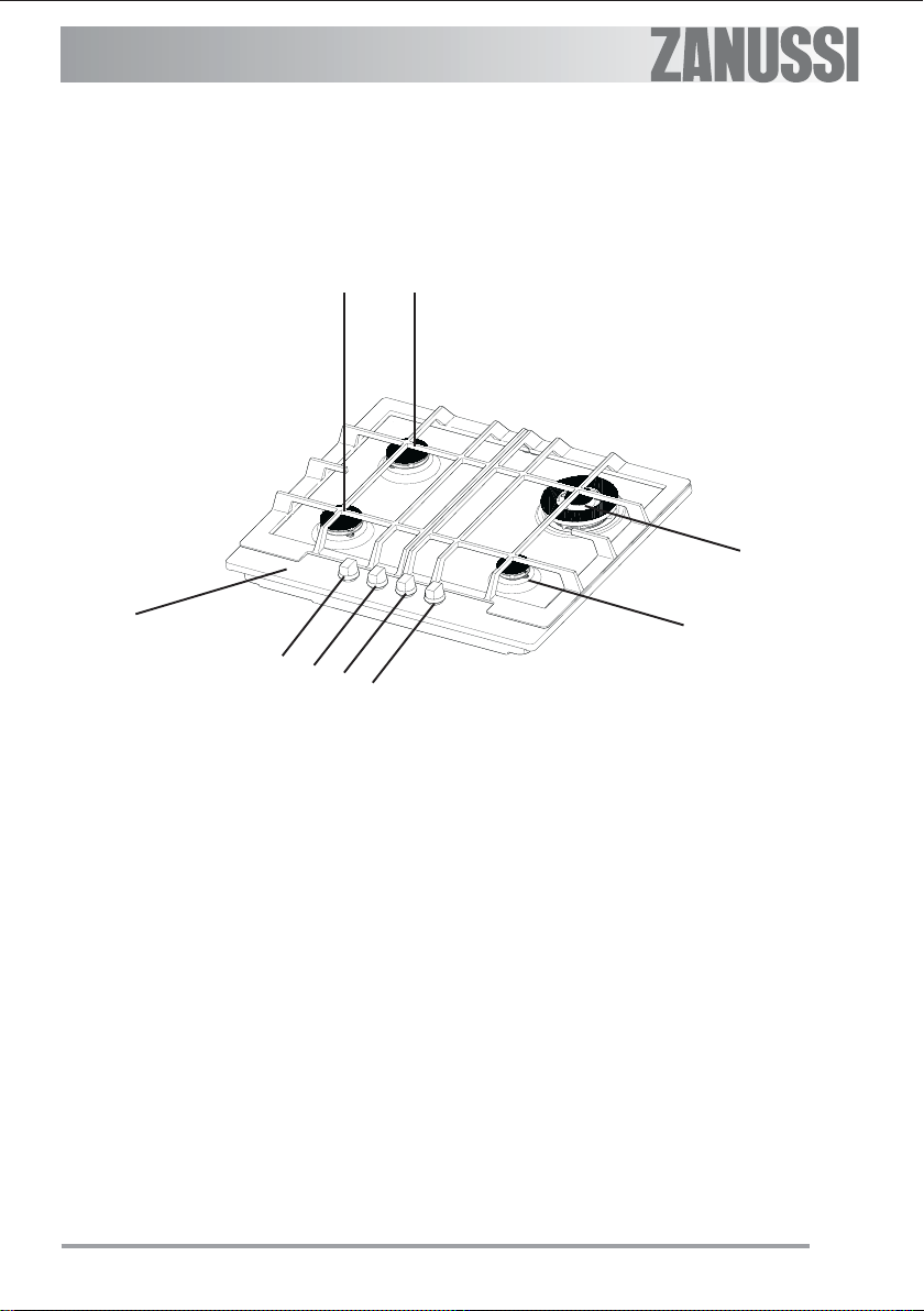
Description of the Hob
3 3
4
1
5
6
7
8
1. Hob Top
2. Auxiliary Burner
3. Semi-rapid Burners
4. Triple Crown Burner
5. Control knob for front left burner (semi-rapid)
6. Control knob for back left burner (semi-rapid)
7. Control knob for back right burner (triple crown)
8. Control knob for front right burner (auxiliary)
2
7
When the hob is first installed
Once the hob has been installed, it is
important to remove any protective
materials, which were put on in the
factory.
Operation
Hob burner control knobs
The symbols on the knobs mean:
= no gas supply
= maximum gas supply
= minimum gas supply
For easier lighting, proceed before
putting a pan on the pan support.
Lighting the burners
!
To light a burner, turn the relevant knob
anticlockwise to maximum position ( ) and
push down the knob to ignite.
Do not keep the control knob pressed
for more than 15 seconds.
If the burner does not light even after
15 seconds, release the control knob,
turn it the "off" position and wait for at
least one minute before trying to light
the burner again.
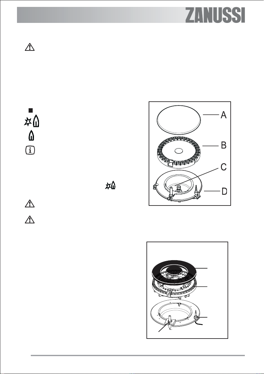
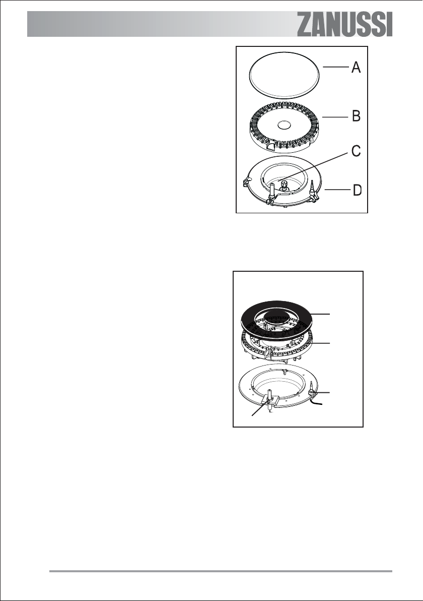
A - Burner cap
B - Burner crown
C - Ignition candle
D - Thermocouple
Triple Crown Burner
After lighting the flame, keep the knob
pushed down for about 5 seconds. This will
allow the "thermocouple" (Figs. letter D) to be
heated and the safety device to be switched off,
otherwise the gas supply would be interrupted.
Then, check the flame is regular and adjust it
as required.
If you cannot light the flame even after
several attempts, check the "cap" (A) and
“crown” (B) are in the correct position.
8
A
B
D
C
In the absence of electricity, ignition can
occur without the electrical device; in this case
approach the burner with a flame, push the relevant knob down and turn it anti-clockwise until
it reaches the "maximum" position.
To switch off burners
!
To put the flame out, turn the knob to the
symbol ( ).
If the burner accidentally goes out, turn
the control knob to the "off" position and
wait for at least 1 minute before trying
to light the burner again.
Take care when frying food in hot oil or
fat, as the overheated splashes could
easily ignite.
When switching on the mains, after installation or a power cut, it is quite normal for
the spark generator to be activated automatically.
9
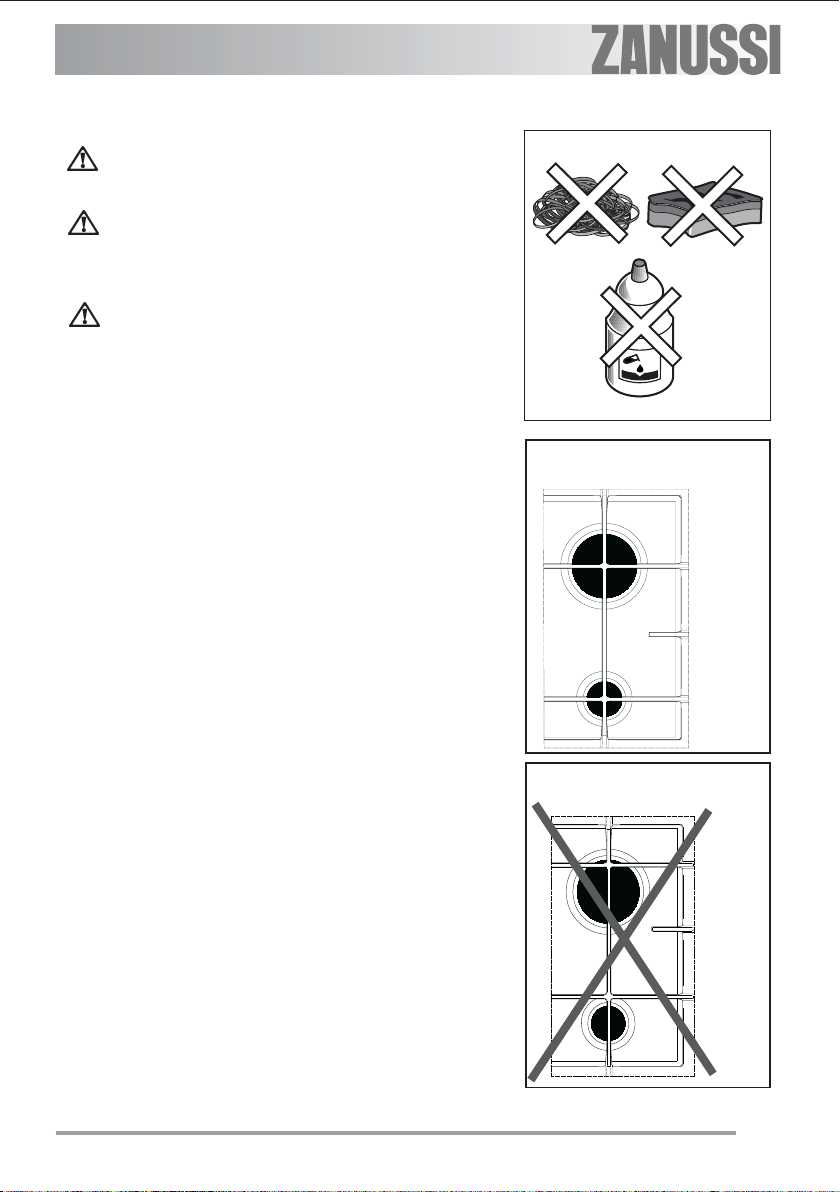
Using the hob correctly
Practical hints
The burners
To ensure maximum burner efficiency, you
should only use pots and pans with a flat bottom
fitting the size of the burner used.
Triple Crown Burner diameter 18-26 cm
Front Semi-rapid Burner diameter 12-18 cm
Rear Semi-rapid Burner diameter 12-22 cm
Auxiliary Burner diameter 8-16 cm
• For easier lighting, proceed before putting a
pan on the pan support.
• Use only pans or pots with flat bottom.
• Take care when frying food in hot oil or fat,
as the overheated splashes could easily
ignite.
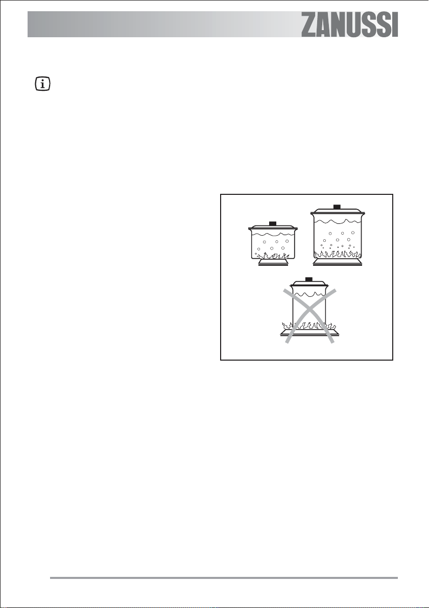
• If you use a saucepan which is smaller than
the recommended size, the flame will spread
beyond the bottom of the vessel, causing the
handle to overheat.
• Prolonged cooking with potstones,
earthenware pans or cast-iron plates is
inadvisable. Also, do not use aluminium
foil to protect the top during use.
• Make sure pots do not protrude over the
edges of the cooktop and that they are
centrally positioned on the rings in order to
obtain lower gas consumption.
• Do not place unstable or deformed pots on the
rings: they could tip over or spill their contents,
causing accidents.
• Pots must not enter the control zone.
• If the control knobs become difficult to turn,
please contact your local Service Force Centre.
• As soon as a liquid starts boiling, turn down
the flame so that it will barely keep the liquid
simmering.
10
Cleaning and Mainteinance
Disconnect the appliance from the
electrical supply, before carrying out
any cleaning or manteinance work.
The hob is best cleaned whilst it is
still warm, as spillage can be removed more easily than if it is left to
cool.
This appliance cannot be cleaned
with steam or with a steam cleaning
machine.
The burners
" The burner caps and crowns can be
removed for cleaning.
" Wash the burners taps and crowns using
hot soapy water, and remove marks with a
mild paste cleaner. A well moistened soap
impregnated steel wool pad can be used
with caution, if the marks are particularly
difficult to remove.
" After cleaning, be sure to wipe dry with a
soft cloth.
" Frequently wash the "caps" and the "crowns"
with hot soapy water, carefully taking away
any built-up of food.
YES
The pan supports
Wash the pan supports using hot soapy water.
Ifnecessary, a paste cleaner or a soap
impregnated steelwool pad can be used with
caution.After cleaning, be sure to wipe dry with
a soft cloth.
Take care when drying them as the enamelling
process occasionally leaves rough edges. If
necessay, remove stubborn stains using a
paste cleaner
" After cleaning, make sure that the pan sup-
ports are correctly positioned.
" To make burners work properly, ensure that
pan supports are placed in a way that the
arms are centred upon the burner as shown
in the picture.
" Pay attention when replacing the pan
supports in order to avoid damaging the
hob top.
NO
11
The Hob Top
" Regularly wipe over the hob top using a soft
cloth well wrung out in warm water to which
a little wasing up liquid has been added.
Avoid the use of the following:
- household detergent and bleaches;
- impregnated pads unsuitable for non-stick
saucepans;
- steel wool pads;
- bath/sink stain removers.
" Should the hob top become heavily soiled,
the following products are recommended:
- For stainless steel hobs use a proprietary
stainless steel cleaner.
- For other hobs use Hob Brite or Bar
Keepers Friend.
" Do not leave acid or alkaline substances
(e.g. vinegar, salt, lemon juice, etc.) on
the cooktop.
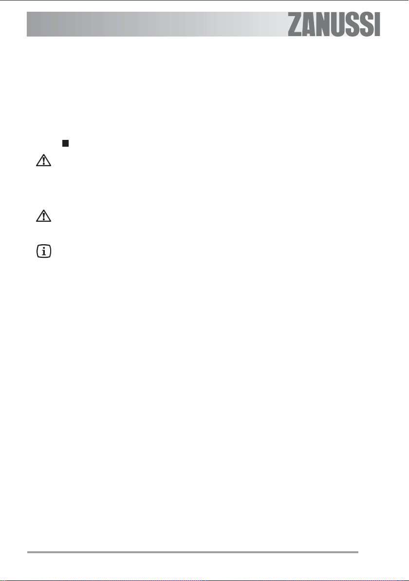
A - Burner cap
B - Burner crown
C - Ignition candle
D - Thermocouple
Triple Crown Burner
The Ignition electrode
The electric ignition is obtained through a
ceramic electrode with a metal electrode (Fig C). Keep these components very clean, to
avoid difficult lighting, and check that the burner
crown holes (Fig - B) are not obstructed.
12
A
B
D
C

Something Not Working?
If the appliance is not working correctly, please carry out the following checks before contacting your local
Service Centre.
SYMPTOM
$ There is no spark when lighting the gas
SOLUTION
# Check that the unit is plugged in and the
electrical supply is switched on.
# Check the mains fuse has not blown.
# Check the burner cap and crown have
been replaced correctly, e.g. after cleaning.
$ The gas ring burns unevenly
# Check the main jet is not blocked and the
burner crown is clear of food particles.
# Check the burner cap and crown have
been replaced correctly, e.g. after cleaning.
If after all these checks, your appliance still does not operate correctly, contact your local Service
Centre.
13

Technical data
Burner gas power (LPG 30 mbar)
Triple crown burner 3,6 kW
Semi-rapid burner 1,6 kW
Auxiliary burner 0,95 kW
Category I3
Gas supply LPG 30 mbar (1 mbar = 10 mm water coloumn).
Gas connection RC 1/2 inch (1/2 inch male)Rear right hand corner
Electric supply 230 V 50 Hz supply, 3 core flexible cable with non rewireable plug.
Appliance class 3
By-pass diameters
Hob dimensions
Width 594 mm
Depth 510 mm
Cut out dimensions
Width 560 mm
Depth 480 mm
Gas burners
Burner Ø By-pass in 1/100 mm.
Auxiliary 28
Semi-rapid 35
Triple crown 56
NOMINAL NOMINAL
POWER POWER NOZZLE GAS FLOW
BURNER kW kCal/h 100/mm RATE
Auxiliary
burner 0,95 814 50 75
Semi-rapid
burner 1,60 1368 066 126
Triplecrown
burner 3,60 3080 98 284
14
g/h

Installation
IMPORTANT
This appliance must be installed by
qualified personnel.
The manufacturer will not accept liability,
should the above instructions or any of
the other safety instructions incorporated
in this book be ignored.
Gas Connection
On the end of the shaft (A) , which includes the GJ
1/2" threaded elbow, an adjustable joint is fixed so
that the washer (B) is fitted between the
components as shown in the diagram.
A drop of paint at both edges of the "L" joint (C) will
evidence that the good seal of the connection has
been tested in the factory.
Before connecting the gas supply pipe to the joint
(C), the installer will ensure that the paint drop is
unbroken and the "L" connector has not been
moved by the vibrations during handling and
transportation.
When the final connection has been made, it is
essential that a thorough leak test is carried out on
the hob and installation. Ensure that the main
connection pipe does not exert any strain on the
hob.
FO 1010
A) End of shaft with nut
B) Washer
C) Adjustable joint
Building In
594
Cut Out Size
The dimensions of the cut-out are given in the
diagram.
510
FO 2038
Dimensions are given in mm.
15

Building over a cupboard or drawer
If the hob is to be installed above a cupboard or
drawer it will be necessary to fit a heat resistant
board below the base of the hob on the underside
of the work surface.
Building over a kitchen unit with door
Proper arrangements must be taken in designing
the furniture unit, in order to avoid any contact with
the bottom of the hob which can be heated when
it is operated. The recommended solution is shown
in the Fig. 1.
The panel fitted under the hob ("a") should be
easily removable to allow easy access if technical
assistance is needed. The space behind the
kitchen unit ("b") can be used for connections.
FO 2044
Building over a kitchen unit with oven
If the hob is built into a kitchen unit with an oven
underneath, the recess must have the dimensions
shown in Fig. 2, and should also incorporate
suitable oven crosspiece supports to ensure an
efficient cooling air circulation.
Figures 3 and 4 give two building-in examples.
The electric connection of the hob and
the oven should be carried out
separately, for electrical safety reasons
to permit easy extraction of the oven
from the front part of the kitchen unit.
a) Removable panel
b) Room for connections
Fig. 2
Fig. 1
16

FO 2041
Fig. 3 Fig. 4
Fitting the hob to the worktop
FO 2042
Carry out the building in of the hob as follows:
• place the seals supplied with the
!
The edge of the hob forms a double seal which
prevents the ingress of liquids.
hob on the front edge of the cut
out. Then, place them at 11 mm
from the side edges and at 10 mm
from the rear edge, as shown in
Fig. 5, taking care that the seals
meet without overlapping;
• place the hob in the cut out, taking
care that it is centred;
• fix the hob with the relevant fixing
clamps and screws, as shown in Fig.
6. When the screws have been
tightened, the excess seal can be
removed.
Fig. 5
Fig. 6
Seal
17

Electrical Connection
Any electrical work required to install
this appliance should be carried out
by a qualified electrician or
competent person, in accordance
with the current regulations.
THIS APPLIANCE MUST BE
EARTHED.
The manufacturer declines any liability should
these safety measures not be observed.
This appliance is designed to be connected to
a 230 V 50 Hz AC electrical supply.
Before the appliance is connected:
1) check that the main fuse and the domestic
installation can support the load (see the
rating label);
2) check that the power supply is properly
earthed in compliance with the current rules;
3) check the socket or the double pole switch
used for the electrical connection can be
easily reached with the appliance built in the
forniture unit. Before switching on, make sure
the electricity supply voltage is the same as
that indicated on the appliance rating plate.
The rating plate is located on the bottom of
the hob. A copy is attached on the back cover
of this book.
The appliance is supplied with a 3 core flexible
supply cord incorporating a plug. Connect the plug
to an adequate socket.
Permanent Connection
In the case of a permanent connection, it is
necessary that you install a double pole switch
between the appliance and the electricity supply
(mains), with a minimum gap of 3 mm between the
switch contacts and of a type suitable for the
required load in compliance with the current electric
regulations.
The switch must not break the yellow and green
earth cable at any point and it should be 2-3 cm
longer than the other cables.
Ensure that the hob supply cord does not
come into contact with surfaces with
temperatures higher than 50 deg. C.
Replacement of the connection cable
The connection of the voltage cable to the
appliance's terminal block is of type "Y". This
means that its replacement requires the
specific equipment of a technician. In this case,
only cable type H05V2V2-F T90 must be used.
The cable section must be suitable to the voltage and the working temperature. The yellow/
green earth wire must be approximately 2 cm.
longer than the phase wires (Fig. 7-a).
To open the terminal block and reach the
terminals, proceed as follows:
" insert the point of a screwdriver into the
visible protrunding part of the terminal block;
" exert a light pressure and lift (Fig. 7-b)
a
Neutral
Earth
(yellow/green)
b
Fig. 7
18

Commissioning
When the hob has been fully installed it will be
necessary to check the minimum flame setting. To
do this, follow the procedure below.
- Turn the gas tap to the MAX position and
ignite.
- Set the gas tap to the MIN flame position then
turn the control knob from MIN to MAX
several times. If the flame is unstable or is
extinguished follow the procedure below.
Procedure:
Re-ignite the burner and set to MIN.
Remove the control knob, use a thin
!
bladed screwdriver to turn the
adjustment screw. Check the flame is
steady and does not extinguish when the
knob is turned from MIN to MAX. Repeat
this procedure for all burners.
Technical Maintenance
Check at regular intervals the condition and
serviceability of the gas connection hose and
pressure regulator, if any is fitted; in case of
malfunction, do not repair but replace the whole
faulty part.
Minimum adjustment screw
To ensure a smooth and safe operation, it is
necessary to periodically grease the gas taps.
19


20

19

הלעפה רושיא
שרדנכ םתבצהו םייריכה תנקתה רחאל ,תילמינימה הבהלה ןוויכ תא קודבל ךרוצ שי .
םשל-ךכ ,םיאבה םידעצב טוקנל שי:
• בצמל הלעפהה רותפכ תא ובבוסMAXרעבמה תא וקילדהו .
• בצמל הלעפהה רותפכ תא ובבוסMINחאו " בצמל כMAXםימעפ רפסמ . הבהלה םא
הביצי הניא ,הבוכ איהש וא ,םיאבה םיבלשה תא ועצב:
הךילהת:
בצמל הבהלה תא ונווכו רעבמה תא שדחמ וקילדהMIN .
הלעפהה רותפכ תא וריסה.
וויכ ךרוצלן , גרבמב ושמתשהחוטש היהת הבהלהש דע ןוויכה גרוב תא ובבוסו
מ רותפכה תא ובבוסתשכ הבכית אלו הביצי-
MINל -MAX . הזה ךילהתה לע ורזח
םירעבמה לכ יבגל.
תינכט הקוזחת
ץחלה תסוו תאו זגה תקפסא תכרעמ תא תועיבקב קודבל ודיפקה)ןקתוה םא .( הרקמב
ללכמה לכ תא ופילחה הלקת לשלקלוקמה.
הקלחו הניקת הלועפ חיטבהל ידכ ,םעפ ידמ הלעפהה ירותפכ תא זרגל ודיפקה.
18

לע הלוע50ºC.
למשחה לבכ תפלחה
יאנכט ידיב קר השעית לבכה תפלחה
אל םייריכה לש למשחה לבכש ואדו
י םמוחש םיחטשמ םע עגמב אוב
תוחיטבה תוארוהל םאתהבו דבלב
ךמסומ , תרבוחב טרופי אל הז ףיעס ךכיפל
וז.
ואלומי אל םא קזנ לכל יארחא וניא ןרציה
לש למשח תשרל םימיאתמ םייריכה
למשחה רוביח
רוביחי תנקתהמ ביוחמה למשח
םייריכה, יע השעי" יאנכט יךמסומ
ב תוגוהנהץרא.
אדוול שי עקשל םירבוחמ םייריכהש
םעהקראה.
הלא תוחיטב תוארוה.
230V, 50Hz .
םייריכה רוביח ינפל:
1. לגוסמ דעוימה ךיתנהש ואדוו
תעב שרדנה סמועב דומעל
םייריכב שומישה)ב ונייעחול תי
םיינכטה םיטרפה.(
2. םא וקדב קראומ למשחה רוביח
יוארכ , תוארוהל םאתהב
למשחב תוחיטבה.
3. ודא ושודה קספמה וא עקשה-
םייריכה שומישל דעוימה יבטוק ,
תולקב םישיגנ ויהי , רשאכ
םמוקמב םינקתומ םייריכה
חבטמה תדיחיב .
למשח לבכ םע םיקפוסמ םייריכה
תלת-םיאתמ עקתו שימג ידיג . ורבח
םאות עקשל עקתה תא.
רויא9
וד קספמ תועצמאב תשרל םירבוחמ ויהי-
תוחיטבה תושירדלו םייריכה תלעפה.
הקראהה רוביח תא קתני אל קספמה
עובק רוביח לש הרקמב , םייריכהש בושח
רוביחעובק
יבטוק , תוחפל היהי םיבטקה ןיב חוורמהש
3מ " תעב שרדנה סמועל םיאתמו מ
)בוהצה דיגה-קורי.(
17

הדובעה חטשמל םייריכה תמאתה
ללחה ךותל םייריכה תא םימיאתמש ינפל ,
םע םיקפוסמה םימטאה תא חינהל שי
ךתחה לש ימדקה קלחה לע םייריכה .
רחאלןכמ , לש קחרמב םתוא חינהל11
מ"ו םידדצה םיילושהמ מ-10מ " מ
םיירוחאה םילושהמ) רויא7 .( אלש ורהזיה
םהיניב תפפוח הבכש היהת . אלש בושח
וז המיטאב םירעפ ורצוויי , עונמל ידכ
םייריכהמ םישלוגש םירמוחמ , לא לוזנלמ
םהיתחתמש תוריגמלו םייריכל תחתמ.
• חתפה לע םייריכה תא וחינה וקדבו
החמוגה זכרמב םיאצמנ םהש.
• םיגרב םע םייריכה תא ועבק
םיספתו) רויא8 .( קודיה רחאל
םיגרבה , קלחה תא קלסל ןתינ
םטאה לש ףדועה.
16

הריגמ וא תינורא לעמ הנקתה
םייריכה תא ןיקתהל םינווכתמ םתא םא
הריגמ וא תינורא לעמ ,חול חינהל םיבייח
טוהירל םייריכה ןיב םוח דדובמ/סיסבל.
הנקתהתלד םע חבטמ תינוראב
ןובשחב תחקל שי , טוהירה ןונכת ןמזב
חבטמל , םע עגמב ואובי אל םיטיהרהש
םייריכה לש ןותחתה קלחה , הז קלחש ןויכ
שומישה ןמזב טהלתהל לולע ןורתפה
רויאב םגדומ ץלמומה3.
םייריכל תחתמש לנפה)
a ( תויהל בייח לק
הלקו החונ השיג רשפאל ידכ הרסהל
ןוקיתב ךרוצ לש הרקמב . רוחאמ חוורמב
a הרסהל ןתינ לנפ
B םירוביחל חוורמ
טוהיר תדיחיב םייריכה תא םיסינכמ םא
רונת םג םהיתחתמו , תבייח החמוגה
רויאב תועיפומה תודימל םיאתהל4
םע םייריכה תא ביכרהל םיבייחותוכמות ,
ריווא תמירז ורשפאיש.
החמוגל םייריכה.
רונת לש למשחה רוביחו למשחה רוביח
םירישכמה.
(b) םירוביחה לכ תא םקמל ןתינ.
הנקתה רונת םע חבטמ תדיחיב
פאיהי
םירויא5ו -6 םה 2 תסנכהל תואמגוד
פאהי למשחל םירבוחמ תויהל םיבייח הי
דרפנב , ימעטמ םגו תוחיטב ימעטמ םג
תוחונ , דחא תא קרפל ךרוצ שישכ
ויהי םייריכה ירוביחש ודיפקה
םידרפנרונתה רוביחמ תוחיטב ימעטמ
לכל השיגה תא יאנכטה לע לקהל ידכו
םירישכמהמ דחא.
15

הנקתה
יאנכט ידי לע ומוקמב ןקתויו בצוי רישכמה זגדבלב ךמסומ.
תימצע הנקתה בקע ומרגיש םיקזנ ןיגב ירחא היהי אל ןרציה היוגש ואהנקתה
דגונהןרציה תוארוה תא ת ,תרבוחב תועיפומה תוחיטבה תוארוה יולימ יא וא.
זגה רוביח
לגה הצקב)A ( גירבת םע ךרב םג ללוכה"GJ 1/2 , היהי ןתינש ךכ ןנווכתמ רבחמ בכרומ
קסדה תא ביכרהלתי) B ( ראותמכ םיביכרה ןיב
רויאבלאמשמש.
L ( ונמסי
רבחמל זגה תנזה רוניצ תא םירבחמש ינפל )C( ,
הפלוק אל עבצה תפיטש אדוול ןיקתמה לע
לש חולשמהו לופיטה ילוטלטב קרופ אל רבחמהו
ועצוב םירוביחהש רחאל ,ופילד ןיאש הקידב עצבל שירוביחה תומוקמבו לגה ךרואל ת.
לגה לע ץחל רצוי אל יזכרמה רוביחה רוניצש ואדוו.
רויאב תועיפומ יטרדנטסה ךתחה תודימ.
לע עבצ תפיט2צק ו רבחמה תו) תרוצב
רושיא תאע םירוביחה תומיטא תקידב "לעפמה י.
םייריכה.
A –םוא םע רוניצה הצק
B -הקסד
C –הצקה רבחמ
ךתחה תודימ
םירטמילימב תומושר ךתחה תודימ
14

ןיקתמל
םיינכט םינותנ
תויללכ תודימ
בחור 580מ "מ
קמוע 510מ "מ
הבוג 88מ "מ
ךתחה תודימ
בחור 560מ "מ
קמוע 480מ "מ
םירעבמה רטוק
ןטק 28מ "מ
םיינוניב 35מ "מ
לודג 56מ "מ
זג ירעבמ-םיקפסה
קפסהמיח ום זג תמירז רעבמ
הזיד100מ "מ םרג/העש
kW kCal/H
ןטק 0.95 814 50 75
ינוניב 1.60 1368 66 126
לודג 3.60 3080 98 284
13

היעב לש הרקמב
הינפה ינפל הלבטב םימושרה םירבדה תא הליחת וקדב יוארכ םילעופ אל םייריכה םא
תורישל.
העפותה ןורתפ
תקלדה ןמזב ץוצינ ןיא
• למשחה תכרעמשו למשחל םירבוחמ םייריכהש ואדוו
הניקת.
• הנגהה ןונגנמש ואדוו) ןקתוה םא (RCCBלעפוה אל .
• במה שארש ואדוו יוארכ םמוקמל ורזחוה רתכהו רע
יוקינה ירחא.
הדיחא אל הבהלה • ךלכולמ אל רתכהשו םסחנ אל רעבמהש ואדוו
וכו ןוזמ תויראשב'.
• יוארכ םמוקמל ורזחוה רתכהו רעבמה שארש ואדוו
יוקינה ירחא.
תוקידבה ירחא םא ,הניקת אל ןידע םייריכה תלועפ ,התוא ובכ , למשחהמ התוא וקתנ
רעבמה
שקתהו זגהוהבורקה תורישה תנחתל ור.
12

ןוילעה חטשמה יוקינ
• תילטמ םע םייריכה תא תוקנל שי
ו םימח םימב הגופס הכר טעמ
םילכ ןובס תסימת.
םיאבה םירמוחה םע תוקנל ןיא:
• הנבלה ירמוחו םיפירח םיטנגרטד.
• וא תושק יוקינ תוירכ וא תושרבמ
תויפיז)וכו טיירב שטוקס'.(
• זרבםילכ ל.
• תינבא יריסמ
םיעבוקמ םירעבמה לש םירתכהו םיסכמה
ע"םיגרב ינש י . תא ומירה םתדרפהל
רתכה , םיגרבה תא וררחשו ותוא וכפה
A רעבמה תפיכ
B רתכ
C התצה רנ)תדורטקלאהתצה (
D ימרת דמצ)ןשיח(
ומוקמל הסכמה תא וריזחהו.
יוקינה רחאל , םיגרבה ינש תא ורבח
) רויא3.(
11

יוקינו הקוזחת
קתנל שי הקוזחת וא יוקינ תולועפ עוציב ינפל
עקשהמ למשחה לבכ תא.
יוקינההיהי וטב רתויכ םרטו תומח םייריכהש
ןיטולחל וררקתה.
םירעבמה
• יוקינ ךרוצל םירעבמה תא ריסהל ןתינ.
• תאו םירעבמה תופיכ תא תורשהל שי
ןובס תסימת םע םימח םימב םירתכה
םע םימתכהו ךולכלה תא ריסהל ןכמ רחאלו
יוקינ תירכ לע יוקינ תחשמ.
• הכר תילטמ םע בטיה בגנל שי יוקינה םויסב
השביו . ןיאםירעבמה תא ריאשהל/ תופיכ
םיבוטר.
• םייריכה לש ןוילעה חטשמה תא תופצל ןיא
ףסכ ריינ םע/וכו םוינימולא'.
• םימל םייריכה ירעבמו תופיכ תא סינכהל ןיא
םירק/םימח ןיידע םהשכ םירשופ.
תותשר
• תותשרה תא ריזחהל שי יוקינה םויסב
לו םוקמלוהנוכנ הרוצב תוחנומ ןהש אד.
• תותשרה תבכרה רויאל םאתהב תישענ 1.
• הלועפה תא ועצב תותשרה תרסהל
רויאב תראותמה2.
• םילכ חידמב תותשרה תא חידהל ןתינ .
תינדי ןתוא םיקנמשכ , ינפל בטיה שבייל שי
םייריכל םתרזחה.
• ע ךולכל תויראש וראשנ םאקתוינש , ץלמומ
יוקינל םידעוימה יוקינ ירמוח םע םריסהל
כרמב השיכרל םינתינה םייריכםילו.
• ו םילכ לזרבב שמתשהל ןיא/תוצמוחב וא.
10

םייריכב ןוכנ שומיש
היגרנאב ליעיו ינוכסח שומיש חיטבהל ידכ , רטוקב תותבחמו םיריס םהילע וביצה
רעבמל םיאתמה)הלבט ואר (תוחוטש תויתחת םע.
ינוניב)ימדק( 12-18ס "מ
ירוחא ינוניב 12-22ס "מ
ריסה/וכו תרבחמה'.
םיאתמ רטוקב החוטש תיתחת.
זתוי אל ןמשהש , תולולע ןמשה תופיטש ןויכ
קלדיהל.
הלבטב , ביבס טשפתהל תולולע תובהלה
ידיל קזנ םורגל ילכהתו.
םייריכה חטשמל . הרוצב םיחנומ םה אלא
הליעי הרוצב זג ךורצל ידכו ריסה לש הליפנ עונמל תנמ לע רעבמה לע הביצי
תינוכסחו.
ילכה.
רעבמ ריסה רטוק
לודג)ריהמ לושיב( 18-26ס "מ
ןטק 8-16ס "מ
• הלה תא ותיצה תחנה ינפל הב
• םיריסב ושמתשה/ םע תוינבת וא תותבחמ
• ורהזיה קומע ןמשב ןוגיט וא היילצ תעשב
• רומאה רטוקהמ ןטק ילכ םתבצה םא
• ץוחמ וטלבי אל םילכה וא תוידיהש ודיפקה
• לש הליפנ וא תוליזנ עונמל ידכ םייריכה לע םיתוועמ וא םיביצי אל םילכ וביצת לא
• הה לנפמ ריסה וקיחרההלעפ.
• הלעפהה ירותפכ תא בבוסל םישקתמ םתאשכ ,תורישל ונפ
• החיתר ףס לע וראשיי םילזונהש ךכ הבהלה תא וכימנה החיתרה ירחא דימ
9

למשח תקספה לש הרקמב ,רורפג םע רעבמה תא תיצהל ןתינ:
הלעפהה רותפכ לע וצחל , תא ותיצהו תילמיסקמ הבהלל ןועשה ןוויכ דגנ ותוא ובבוס
רורפגה םע הבהלה.
רעבמה תא תובכל ידכ
רוגס בצמל רעבמה רותפכ תא ובבוס .
דחוימב וחיגשה ,וש םע םינגטמ וא םילשבמשכןמשו ןמ , םורגל םילולע םה יכ
ידמ רתוי םיממוחמ םה םא הפירשל.
שאה תא תובכל ורכז ,רעבמהמ לושיבה תרסה ינפל הבהלה תא ןיטקהל וא.
וא ישארה זגה זרב תא םיחתופ םתאשכלמשח תקספה םויסב , תצמש ןכתי
לעפויתיטמוטוא .הלקת הניא וז.
8

הנקתהה רחאל
ירמוח לכ תא ריסהל ודיפקה הנקתהה ירחא
הזיראה.
הלעפה
הלעפהה יבצמ טוטרש:
יובכ–זג תנזה ןיא
תילמיסקמ הבהל
תילמינימ הבהל
תחנה ינפל התצהה תא עצבל ץלמומ
רעבמה לע ילכה.
רעבמה תפיכ
רתכ
התצה רנ)תדורטקלאהתצה (
ימרת דמצ)יחןש(
תילמיסקמ הבהל בצמל ןועשה ןוויכ דגנ םיאתמה
תא ליעפהל ידכ המינפ רותפכה לע וצחלו
שלושמ רתכ רעבמ
בצמל ותוא ובבוסו רותפכה תא וררחש
OFF .
מ תיצהל וסנו תוחפל הקד וניתמהשדח.
תונויסינ רפסמ רחאל תצוה אל רעבמה םא , וקדב
רעבמ תתצה
רעבמה תתצהל , ובבוס הלעפהה רותפכ תא
תצמה.
מ רתוי הלעפהה רותפכ לע וצחלת לא-15
תופיצרב תוינש.
רחאל תתצינ אל הבהלה םא15תוינש ,
התצהה רחאל , רותפכ לע ץוחלל וכישמה
כ ךשמב הלעפהה-5 רשפאל ידכ תופסונ תוינש
D (םמחתהל . ןכמ רחאל
הבכי תוחיטבה ןונגנמ . תא ונווכ ןכמ רחאל
ימרתה דמצל) רויא
יוצרה הבוגל הבהלה .
A ( רתכהו)B ( הרוצב םיחנומ הנוכנ
ה םא"הפיכ) "
רעבמה לע.
7

שמתשמל
םייריכה רואית
1. םייריכה לש ןוילע חטשמ
2. ןטק רעבמ.
3. םיינוניב םירעבמ
4. שלושמ רתכ רעבמ
5. תימדק תילאמש הבהלל הלעפה רותפכ) רעבמינוניב(
6. תירוחא תילאמש הבהלל הלעפה רותפכ) ינוניב(
7. תירוחא תינמי הבהלל הלעפה רותפכ) שלושמ רתכ(
8. פה רותפכתימדק תינמי הבהלל הלע) ןטק(
6

תוארוהב ןיוצמה לדוגה לעמ.
ןוזמ וב ןיאש/םילזונ.
אל דחוימבו רמוח לכב תותשרהו
ףסכ ריינב.
חטשמ לע הכירח ימתכל םורגל
םייריכה . הרקמב לוחת אל הז
םייריכל תוירחאה.
תוניקתה תא אדול שי םייריכהמ
בושח!
ןמזב וקוזינ אל םהשו םהלש
• רחא ילכב וא ריסב שמתשהל ןיא
חולשמה . והשלכ קזנ לש הרקמב
• הזיראה ירמוח תרסה רחאל
הנקתהה ךשמה תא ורצע
• רחא ילכ וא ריסב שמתשהל ןיא
רכומל ורשקתהו.
• םייריכה חטשמ תא תופצל ןיא
תוארוהל םאתהב םירמוח תכלשה
• לוכי ולא תוארוהל דוגינב שומיש
רוזחמל םידעוימה רוזאב תוגוהנה
יתלבל וכפהל-ע שימש" ךותיח י
ולש למשחה לבכ.
לפוטי אל רצומהש ןמסמ הזיראה
תיתיב הפשאכ . שי תאז םוקמב
םיילמשחה םיביכרה רוזחמ ךרוצל
םיינורטקלאהו . תוארוה לע הדפקה
תוכיא תרימש תא וחיטבי רוזחמה
הביבסה תוכיאב עגפי תוארוהה
םכתביבסב םישנאה תואירבבו .
רוזחמה אשונב םיפסונ םיטרפל
וא תומיאתמה תויושרל ורשקתה
תא םתשכר הב תונחלרצומה.
ה תוכיא הביבס
• הזיראה ירמוח תא ךילשהל שי
םכירוגמ.
• ןשי רישכמ םיכילשמשכ , ודיפקה
• לומיסה לע וא רצומה לע
וא ריבעהל ףוסיאה תדוקנל ות
הביבסה . יולימ לע הדפקה יא
5

תובושח תוחיטב תוארוה
תלעפה ינפלו הנקתהה ינפל הז דומעב תועיפומה תוארוהה תא ןויעב אורקל שי
םייריכההנושאר םעפב .
למשחה עקשמ םקתנל.
םידלי תוחיטב
דבלב םירגובמ . םכידליש וחיגשה
אלשו רונתה תברקב וקחשי אל
החגשה אלל ותוא וליעפי.
םהשכ דואמ םמחתהל םייושע
שומישב . םהמ םידלי קיחרהל שי
וררקתיש רחאל דע.
שהי ידיב קר ועצובי םינוקיתהו תור
ךמסומ יאנכט.
רישכמה תא קתנל שי הקוזחת
למשחה עקשמ.
םייריכה . רוציל לולע רורוואב רסוח
ןצמחב רוסחמ.
ה לש תוזידהבמםירעיפכ
לש םינותנה תיוותב תועיפומש
תנזה רוניצ דיל תמקוממה םייריכה
זגה.
רדחב תוחלו םוח תקפהל םרוג זג
חבטמה לש בוטו)וכו חותפ ןולח' .(
ןולח ןיא םא , ןקתה ןיקתהל די
ינכמ רורווא)הטנו ,וכו םידא טלוק'.
רתוי יתועמשמ רורווא , המגודל
ינכמ רורווא וא חותפ ןולח
רתוי יתועמשמ.
• שומישב םניא םייריכה םא , שי
דבלב ךמסומ יאנכט.
• ידיב שומישל דעוימ רונתה
קוזינ אל רונתהש אדוול לבכשו
םלשומ בצמב למשחה . ןיא םא
גיצנ םע ורשקתה ךכ רבדה
• רונתב םימיוסמ םישיגנ םיקלח
הנקתהה ינפל הרבחה.
איהש הרוצ.
הלעפהה ןמזב
הנקתה ,הקוזחתו יוקינ
• בל ןיאדבל םינוקית עצ . תודובע לכ
ירחסמ שומישל םידעוימ םניא ,
• וא יוקינ תולועפ עוציב ינפל
• רוזאב ףיצר רורווא שיש ואדו
םייריכה ןויקינ לע רומשל .
ןוזמ תויראש לש תורבטצה
• זגה תקפסאש ואדו גוסל תמאות
תוחקלתהל םורגל םילולע םינמושו.
ידיב ךכל וכמסוהש םיאנכט ידיב
• לע לעופה לושיב רישכמב שומיש
דבלב םיירוקמ םיפלחב.
)חבטמב .( ףיצר רורווא אדוול שי
םייובכ םייריכהשכ.
יקלח םע עגמב ואובי אל למשחה
• ףיצר שומיששוממו שרוד רונתב ך
םילולעש םיממחתמה םייריכה
םילבכה תוניקתב עוגפל.
תורטמליב ןוזמ ירצומ לש לוש
ויכו יתיישעת"ב.
רצומה יטרפמב.
ןפוא םושב . ושעיי םינוקיתה לכ
םוקמ תברקב , ילבכש חיטבהל שי
הנקתה
דבלב תרחא הרטמ םושל אלו. םה
ונתרבח .הב ךרוצ שי םא תפלח
םיקלח , שמתשהל יאנכטהמ ושרד
• ידי לע ומוקמב ןקתויו בצוי רישכמה
• תרסה רחאל הזיראה יקלח לכ שי
• ב םהשלכ םייוניש עצבל ןיא לכ
• הםייריכדעוימ יתיב שומישל םי
• סנל ןיא םהשלכ םייוניש עצבל תו
• תויתוחיטבו תוינייגיה תוביסמ , שי
• דבל םייריכה תא ןקתל תוסנל ןיא
• וד בצמב םירותפכה לכש ואOFF
• ףסונ ילמשח רישכמ םירבחמ םא
4

םיניינעה ןכות
םייריכה רואית..........................................................................................6
הנקתהה רחאל........................................................................................7
הלעפה...................................................................................................7
םייריכב ןוכנ שומיש...................................................................................9
יוקינו הקוזחת....................................................................................10
היעב לש הרקמב....................................................................................12
הנקתה.................................................................................................14
הלעפה רושיא........................................................................................18
תינכט הקוזחת.......................................................................................18
הלעפהה תוארוהב שומישל ךירדמ
הכרדהה ךלהמב םכתא תוחנהל ידכ תונושה תוארוהה דיל ועיפוי םיאבה םילמסה:
רוהתובושח תוחיטב תוא..................................................................................4
שמתשמל...........................................................................................6
ןיקתמל.............................................................................................13
תוחיטב תוארוה
תוצעו םיפיט
הביבסה תוכיא תרימשל רשקב עדימ.
די גשיהב הלעפהה תוארוה תרבוח תא רומשל שי . ידיל רסמנ רישכמה םא
םירחא , םישמתשמהש ידכ םייריכה םע רסמית וזה תרבוחהש גואדל שי
ו ליעפהל ועדי םירחאהל לפטהנוכנ הרוצב םהב.
3

2

הלעפהו שומיש תוארוה
לזג םייריכ
ZGS 688
ירצומ ישכור תחפשמל ךתופרטצה
םיליעפמ דציכ ריבסהלו תוחנהל ודעונ שומישה תוארוהםייריכשידח םי
םגד
תרבחתויונכוס ןזךתוא תכרבמ םע
הרבחה
ללכושמוםי הלא , תובוטה תואצותה תא לבקלו תלעותה אולמ תא קיפהל ידכ
רתויב.
עב תויונכוס ןז"מ , הדוצמה31 ,א.היישעת , דוקימ רוזא58001
35696-8001 07/07 R.0
 Loading...