

User
Manual
Návod k
použití
Gas
Hob
Plynová
varná deska
ZGS 646
CZ
HR
RO
SK
UA

Thank you for selecting our applianceThank you for selecting our appliance
Thank you for selecting our appliance
Thank you for selecting our applianceThank you for selecting our appliance
We wish you lots of enjoyment with your new appliance and we hope that
you will consider our brand again when purchasing household appliances.
Please read this user manual carefully and keep it throughout the product
life cycle as a reference document. The user manual should be passed on
to any future owner of the appliance.
2
Contents
For the User
Important safety information .............................................................................. 4
Operation .......................................................................................................... 6
Using the hob correctly ..................................................................................... 8
Cleaning and Maintenance ................................................................................ 9
Service and original Spare Parts ...................................................................... 21
European Guarantee ....................................................................................... 21
For the Installer
Technical data ................................................................................................. 11
Installation ....................................................................................................... 13
Adaptation to different types of gas ................................................................. 15
Electrical connection ....................................................................................... 16
Building in ....................................................................................................... 18
Possibilities for insertion .................................................................................. 20
Guide to Use the instructions
The following symbols will be found in the text to guide you throughout the
Instructions:
Safety Instructions
Step by step instructions for an operation
)
Hints and Tips
Environmental information
This appliance complies with the following E.E.C. Directives:
2006/95 2006/95
•
2006/95 (Low Voltage Directive);
2006/95 2006/95
89/336 89/336
•
89/336 (Electromagnetical Compatibility Directive);
89/336 89/336
90/396 90/396
•
90/396 (Gas Appliances);
90/396 90/396
93/68 93/68
•
93/68 (General Directives)
93/68 93/68
and subsequent modifications.
MANUFACTURER:MANUFACTURER:
MANUFACTURER:
MANUFACTURER:MANUFACTURER:
ELECTROLUX HOME PRODUCTS ITALY S.p.A.
Viale Bologna, 298
47100 FORLÌ (Italy)
3
ENGLISH
Important safety information
This warnings has been given for the safety of you and others. We therefore
ask you to carefully read the procedures of installing and using this cooker.
Installation
z The work of installation must be
carried out by competent and qualified
installers according to the regulations
in force.
• Any modifications to the domestic
electrical mains which may be
necessary for the installation of the
appliance should be carried out only
by competent personnel.
During Operation
• This appliance has been designed for
non professional purpose in private
houses only. It is meant to cook edible
foodstuff only and must not be used
for any other purposes.
• It is dangerous to alter the specification
in any way.
• For hygiene and safety reasons, this
appliance should be kept clean at all
times. A build-up of fats or other
foodstuff could result in a fire.
• Under no circumstances should you
attempt to repair the appliance
yourself. Repairs carried out by
unexperienced persons may cause
injury or serious malfunctioning. Refer
to your local Service Centre. Always
insist on genuine spare parts.
• Ensure that all control knobs are in the
OFF position when not in use.
• Should you connect any electrical tool
to a plug near this cooking appliance,
ensure that electric cables are not in
contact with it and keep them far
enough from the heated parts of this
appliance.
4
• If the appliance is out of order,
disconnect it from the electric supply.
People Safety
• This appliance has been designed to
be operated by adults and children
under supervision. Young children
must not be allowed to tamper with the
controls or play near or with the oven.
• This appliance is not intended for use
by children or other persons whose
physical, sensory or mental capabilities
or lack of experience and knowledge
prevents them from using the
appliance safely without supervision or
instruction by a responsible person to
ensure that they can use the appliance
safely.
• Accessible parts of this appliance may
become hot when it is in use. Children
should be kept away until it has
cooled.
About Installation, Cleaning and
Maintenance
z It is mandatory that all operations
required for the installation are carried
out by a qualified or competent
person, in accordance with existing
rules and regulations.
• Disconnect the appliance from the
electrical supply, before carrying out
any cleaning or manteinance work.
• Ensure a good ventilation around the
appliance. A poor air supply could
cause lack of oxygen.
• Ensure that the gas supply complies
with the gas type stated on the
identification label, placed near the gas
supply pipe.

• This appliance is not connected to a
combustion products evacuation
device. It must be installed and
connected in accordance with current
installation regulations. Particular
attention shall be given to the relevant
requirements regarding ventilation.
• The use of a gas cooking
appliance results in the production
of heat and moisture in the room in
which it is installed. Ensure that
the kitchen is well ventilated: keep
natural ventilation holes open or
install a mechanical ventilation
device (mechanical extractor
hood).
• Prolonged intensive use of the
appliance may call for additional
ventilation, for example opening of
a window, or more effective
ventilation, for example increasing
the level of mechanical ventilation
where present.
• Once you removed all packaging from
the appliance, ensure that it is not
damaged and the electric cable is in
perfect conditions. Otherwise, contact
your dealer before proceeding with the
installation.
• The manufacturer disclaims any
responsability should all the safety
measures not be carried out.
Service
• Under no circumstances should you
attempt to repair the appliance
yourself. Repairs carried out by
unexperienced persons may cause
injury or serious malfunctioning. Refer
to your local Service Centre. Always
insist on genuine spare parts.
Environmental Information
z After installation, please dispose of
the packaging with due regard to
safety and the environment.
• When disposing of an old appliance,
make it unusable, by cutting off the
cable.
The symbol on the product or
on its packaging indicates that this
product may not be treated as household
waste. Instead it shall be handed over to
the applicable collection point for the
recycling of electrical and electronic
equipment. By ensuring this product is
disposed of correctly, you will help
prevent potential negative consequences
for the environment and human health,
which could otherwise be caused by
inappropriate waste handling of this
product. For more detailed information
about recycling of this product, please
contact your local city office, your
household waste disposal service or the
shop where you purchased the product.
It is very important that this
instruction book should be kept
safely for future consultation. If the
appliance should be sold or given to
another person, please ensure that
the booklet goes together with it, so
that the new owner can know of the
functions of the machine and also be
aware of the warnings.
These instructions are only for the
countries stated by the symbol printed
on the front cover of this instruction
book.
5
Operation
Hob burner control knobs
The symbols on the knobs mean:
= no gas supply
= maximum gas supply
= minimum gas supply
For easier lighting, proceed before
putting a pan on the pan support.
Lighting the burners
)
Push the relevant knob down and
turn it anti-clockwise until it reaches
the "maximum" position.
After lighting the flame, keep the
knob pushed down for about
secondsseconds
seconds. This will allow the
secondsseconds
AA
A,
AA
DD
D) to
DD
BB
B) are
BB
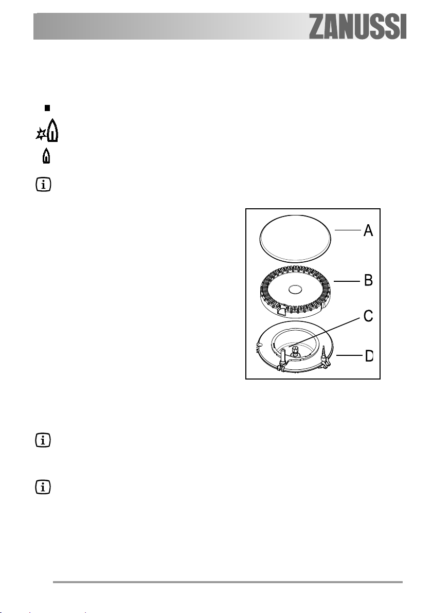
"thermocouple" (see figure - lett.
be heated and the safety device to be
switched off, otherwise the gas supply
would be interrupted.
Then, check the flame is regular
and adjust it as required.
If you cannot light the flame even
after several attempts, check the "cap"
and “crown” (see figure - lett.
in the correct position.
When switching on the mains, after
installation or a power cut, it is quite normal for the spark generator to
be activated automatically.
In the absence of electricity, ignition can occur without the
electrical device; in this case
approach the burner with a
flame, push the relevant knob
down and turn it anti-clockwise
until it reaches the "maximum"
position.
55
5
55
A - Burner cap
B - Burner crown
C - Ignition candle
D - Thermocouple
6
Do not keep the control knob
pressed for more than 15 seconds.
If the burner does not light
even after 15 seconds, release
the control knob, turn it the
"off" position and wait for at
least one minute before trying
to light the burner again.
If the burner accidentally goes
out, turn the control knob to the
“off” position and wait for at
least 1 minute before trying to
light the burner again.
To switch off burners
)
To put the flame out, turn the knob to
the symbol ( ).
7

Using the hob correctly
Practical hints
The burners
To ensure maximum burner
efficiency, you should only use pots and
pans with a flat bottom fitting the size of
the burner used.
Rapid Burner diameter 18-26 cm
Semi-rapid Burner diameter 12-22 cm
Auxiliary Burner diameter 8-16 cm
• For easier lighting, proceed before
putting a pan on the pan support.
• Use only pans or pots with flat bottom.
• Take care when frying food in hot
oil or fat, as the overheated
splashes could easily ignite.
• If you use a saucepan which is smaller
than the recommended size, the flame
will spread beyond the bottom of the
vessel, causing the handle to overheat.
• Prolonged cooking with
potstones, earthenware pans or
cast-iron plates is inadvisable.
Also, do not use aluminium foil to
protect the top during use.
• Make sure pots do not protrude over
the edges of the cooktop and that they
are centrally positioned on the rings in
order to obtain lower gas
consumption.
• Do not place unstable or deformed
pots on the rings: they could tip over or
spill their contents, causing accidents.
• Pots must not enter the control zone.
• If the control knobs become difficult to
turn, please contact your local Service
Force Centre.
• As soon as a liquid starts boiling, turn
down the flame so that it will barely
keep the liquid simmering.
8

Cleaning and Mainteinance
Disconnect the appliance from
the electrical supply, before
carrying out any cleaning or
manteinance work.
The hob is best cleaned whilst
it is still warm, as spillage can
be removed more easily than if
it is left to cool.
This appliance cannot be
cleaned with steam or with a
steam cleaning machine.
The burners
z The burner caps and crowns can be
removed for cleaning.
z Wash the burners taps and crowns
using hot soapy water, and remove
marks with a mild paste cleaner. A
well moistened soap impregnated
steel wool pad can be used with
caution, if the marks are particularly
difficult to remove.
z After cleaning, be sure to wipe dry
with a soft cloth.
z Frequently wash the "caps" and the
"crowns" with hot soapy water,
carefully taking away any built-up of
food.
The Hob Top
z Regularly wipe over the hob top
using a soft cloth well wrung out in
warm water to which a little wasing
up liquid has been added. Avoid the
use of the following:
- household detergent and bleaches;
- impregnated pads unsuitable for
non-stick saucepans;
- steel wool pads;
- bath/sink stain removers.
9
z Should the hob top become heavily
soiled, the following products are
recommended:
- For stainless steel hobs use a
proprietary stainless steel cleaner.
- For other hobs use Hob Brite or Bar
Keepers Friend.
z Do not leave acid or alkaline
substances (e.g. vinegar, salt,
lemon juice, etc.) on the cooktop.
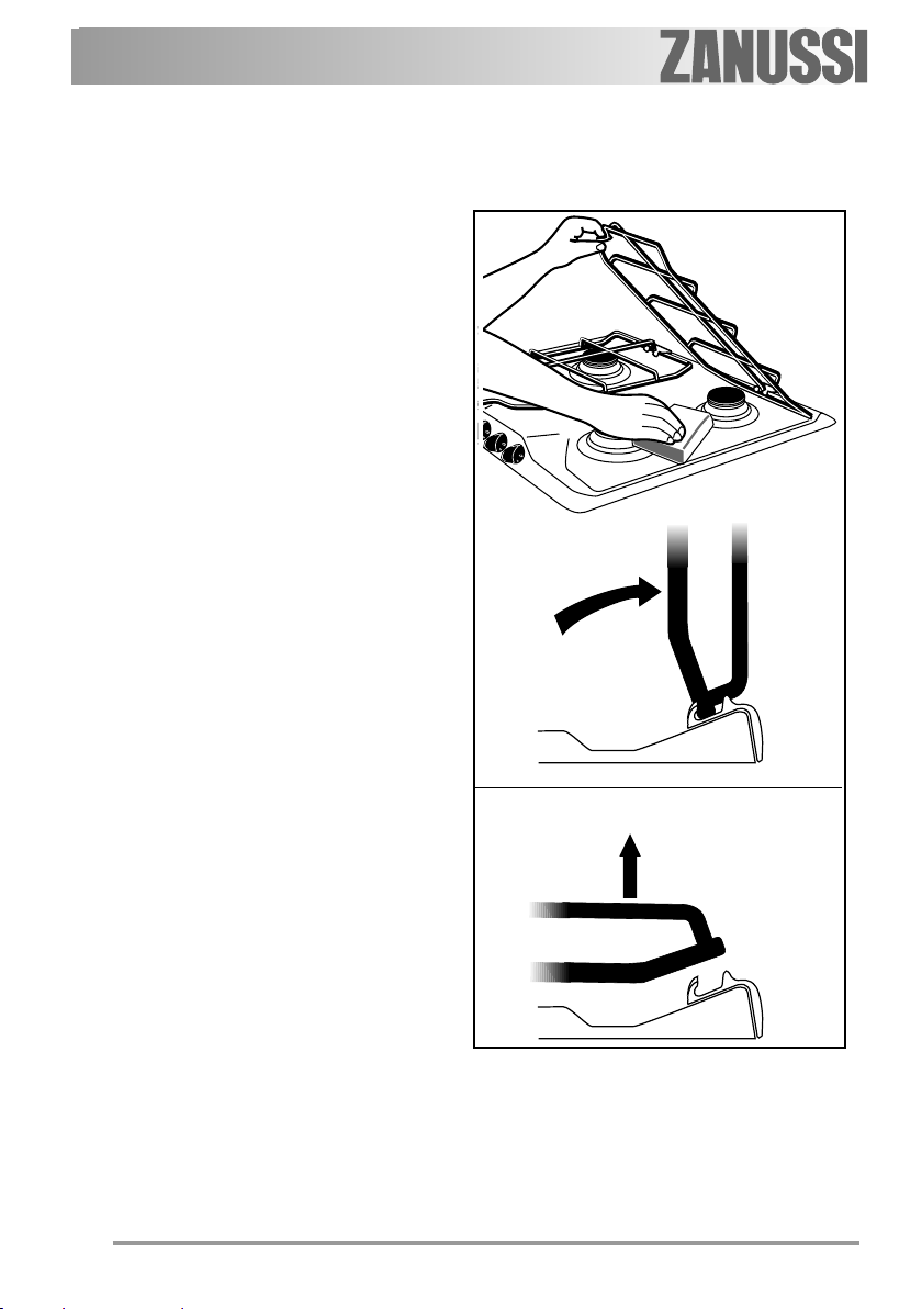
Pan supports
The hob is provided with enamelled pan
supports (thin and light).
To keep the pan supports in the right
position, they are hooked to a couple of
special hinges in the back of the hob.
Thanks to these hooks, you can lift the pan
supports for easier cleaning, as shown in
the picture.
To take the pan supports completely off the
hob, proceed as shown in the picture.
The pan supports are dishwasher proof.
The Ignition electrode
The electric ignition is obtained
through a ceramic electrode with a
metal electrode. Keep these
components very clean, to avoid difficult
lighting, and check that the burner
crown holes are not obstructed.
Periodic Maintenance
Periodically ask your local Service Centre
to check the conditions of the gas supply
pipe and the pressure adjuster, if fitted.
10
Technical data
Rapid burner 3,0 kW (natural gas) - 2,8 kW (liquid gas)
Semi-rapid burner 2,0 kW
Auxiliary burner 1,0 kW
Category II2H3+
Gas supply natural gas G20 (2H) 20 mbar
Gas connection G 1/2"
Electric supply 230 V~ 50 Hz
Appliance class 3
Hob dimensions
Width 580 mm
Depth 510 mm
Cut out dimensions
Width 560 mm
Depth 480 mm
By-pass diameters
Burner Ø By-pass in 1/100 mm.
Auxiliary 28
Semi-rapid 32
Rapid 42
11
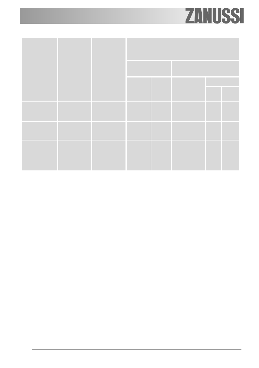
Gas burners
NORMAL REDUCED
POWER POWER
BURNER NATURAL GAS LPG
G20 (2H) - 20 mbar
kW kW g/h
inj. m3/h inj.
100/mm 100/mm
Auxiliary
burner 1,0 0,33 70 0,095 50 73 71
Semi-rapid
burner 2,0 0,45 96 0,190 71 145 143
Rapid 3,0
burner (natural gas) 0,75 119 0,286 86 204 200
2,8
(
liquid gas
)
NORMAL
POWER
(Butane/Propane) 30 mbar
G30 G31
12

Installation
• The following instructions about
installation and maintenance must
be carried out by qualified
personnel in compliance with the
regulation in force.
• The appliance must be electrically
disconnected before all
interventions. If any electric supply
to the appliance is required to
carry out the work, ensure all the
necessary precautions are
followed.
• The side walls of the unit in which
the hob is going to be installed,
must not exceed the height of the
working top.
• Avoid installing the appliance in
the proximity of inflammable
materials (e.g. curtains, tea towels
etc.).
THE MANUFACTURER WILL NOT
ACCEPT LIABILITY, SHOULD ANY
OF THE OTHER SAFETY
INSTRUCTIONS INCORPORATED IN
THIS BOOKLET OR THE
REGULATION IN FORCE BE
IGNORED.
Gas connection
Choose fixed connections or use a
flexible pipe in stainless steel in
compliance with the regulation in force.
If using flexible metallic pipes, be careful
they do not come in contact with mobile parts or they are not squeezed. Use
the same attention when the hob is
combinated with an oven.
13
IMPORTANT - To ensure a correct
operation, a savingof energy and the
long life of the appliance, the voltage
pressure of the appliance must
correspond to the recommended values.
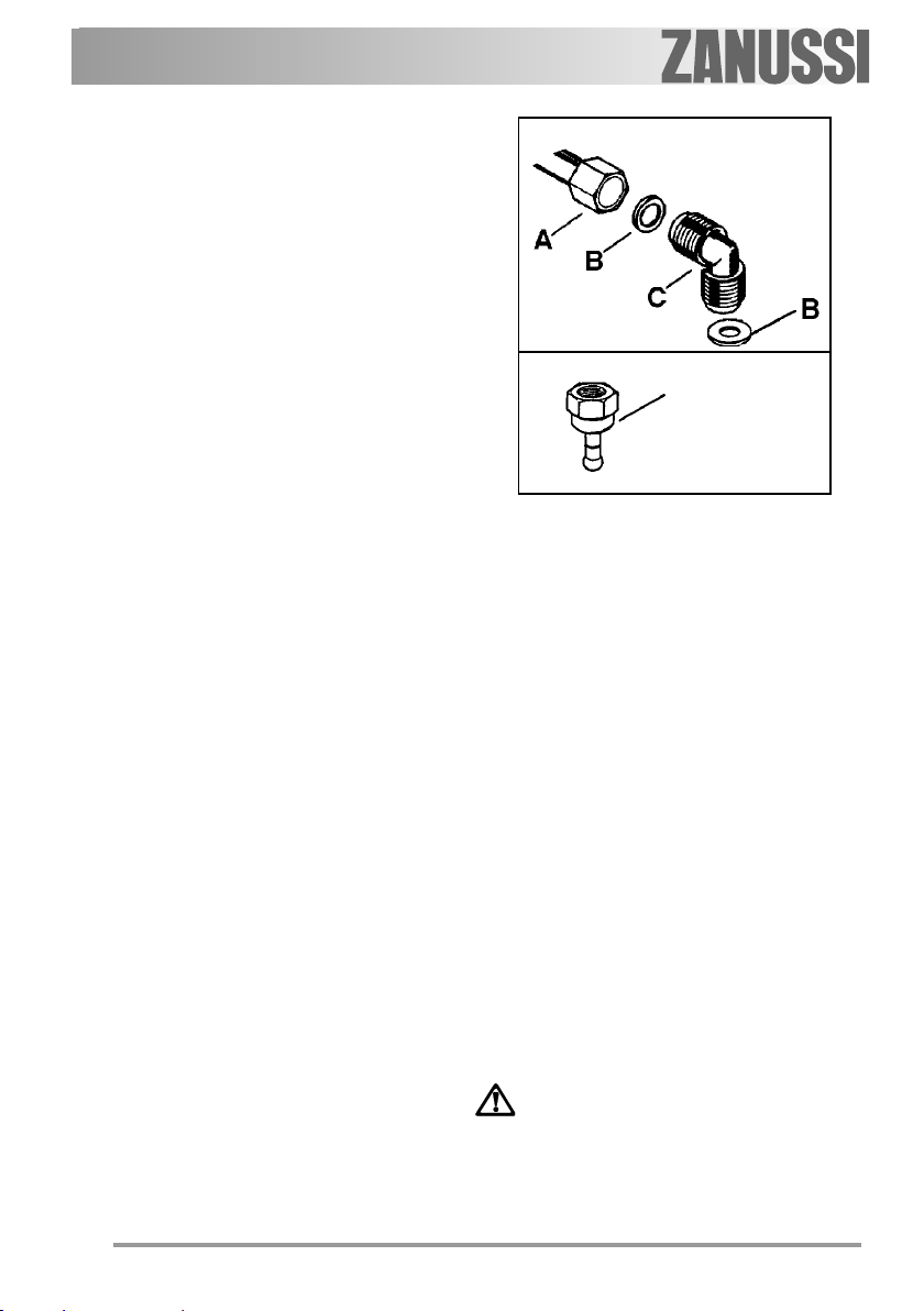
The adjustable connection is fixed to the
comprehensive ramp by means of a
threaded nut G 1/2". Interpose the
sealing between the components as
shown in the picture. Screw the parts
without forcing, adjust the connection in
the required direction and tighten
everything.
Connection using flexible nonmetal
pipes
When the connection can be easily
inspected in its full extent, there is the
chance to use a flexible pipe according
to the rules in force. The flexible pipe
must be tightly fixed using clamps
according to the rules in force.
Liquid gas:
use the rubber pipe holder
«D» (according to the local regulations
in force). Always insert the gasket «B».
Then proceed with the gas connection.
The flexible pipe should be made ready
for use in such a way that:
- nowhere it can reach overtemperature,
other than room temperature, higher
than 30°C; if the flexible pipe, to reach
the cock, must run behind the range,
it must be installed as shown in picture;
- it is no longer than 1500 mm;
- it shows no throttles;
- it is not subject to traction or torsion;
- it doesn't get in touch with cutting
edges or corners;
- it can be easily inspected in order to
check its condition.
The control of preservation of the flexible
Natural gas
Liquid gas
D
A) Ramp with ending nut
B) Seal
C) Adjustable connection
D) Rubber pipe holder for
pipe consists in checking that:
- it doesn't show cracks, cuts, marks
of burnings bothon the end parts and
on its full extent;
- the material is not hardened, but
shows its normal elasticity;
- the fastening clamps are not rusted;
- expiry term is not due.
If one or more abnormalities are seen,
do not repair the pipe, but replace it.
IMPORTANT
Once installation is complete,
check the perfect seal of every
pipe fitting, using a soapy
solution, never a flame.
liquid gasliquid gas
liquid gas
liquid gasliquid gas
14
Adaptation to different types of gas
A. Injectors replacement
)
• Remove the pan supports.
• Remove the burner's caps and
crowns.
• With a socket spanner 7 unscrew
and remove the injectors (Fig. 1), and
replace them with the ones required
for the type of gas in use (see table
«Gas burners»).
• Reassemble the parts, following the
same procedure backwards.
• Replace the rating label (placed near
the gas supply pipe) with the relevant
one for the new type of gas supply.
You can find this label in the package
of the injectors supplied with the
appliance.
Should the feeding gas pressure be
different or variable compared with the
required pressure, an appropriate
pressure adjuster must be fitted on the
gas supply pipe, in compliance with the
rules in force.
Fig. 1
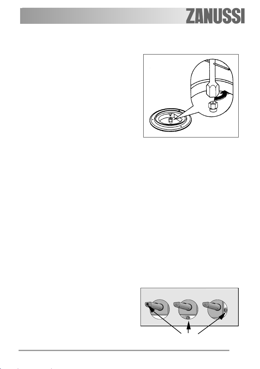
B. Adjustment of minimum
)
level
To adjust the minimum level of the
burners, proceed as follows:
• Light the burner.
• Turn the knob on the minimum
position.
• Remove the knob.
• With a thin screwdriver, adjust the
by-pass screw control shaft (see Fig.
2).
If changing from natural gas to liquid
gas, completely tighten the
adjustment screw in.
If changing from liquid gas to natural
gas, undo the by-pass screw about
1/4 of a turn.
• Finally check the flame does not go
out when quickly turning the knob
from the maximum position to the
minimum position.
This procedure can easily be carried
out, anyhow the hob has been
positioned or built in the working top.
Fig. 2
Minimum adjustment screw
15

Electrical connection
The appliance is designed to be
connected to 230 V monophase
electricity supply.
The connection must be carried out
in compliance with the laws and
regulations in force.
Before the appliance is connected:
1) check that the main fuse and the
domestic installation can support the
load (see the rating label);
2) check that the power supply is
properly earthed in compliance with the
current rules;
3) check the socket or the double
pole switch used for the electrical
connection can be easily reached with
the appliance built in the forniture unit.
The appliance is supplied with a
connection cable. This has to be
provided with a proper plug, able to
support the load marked on the
identification plate. The plug has to be
fitted in a proper socket.
If connecting the appliance directly
to the electric system, it is necessary
that you install a double pole switch
between the appliance and the
electricity supply, with a minimum gap
of 3 mm. between the switch contacts
and of a type suitable for the required
load in compliance with the current
rules.
The connection cable has to be
placed in order that, in each part, it
cannot reach a temperature 50°C
higher than room temperature.
The brown coloured phase cable
(fitted in the terminal block contact
marked with "L") must always be
connected to the network phase.
16

Remplacement of the voltage
cable
The connection of the voltage cable
to the appliance's terminal block is of
type "Y". This means that its
replacement requires the specific
equipment of a technician. In this case,
only cable type H05V2V2-F T90 must
be used. The cable section must be
suitable to the voltage and the working
temperature. The yellow/green earth
wire must be approximately 2 cm.
longer than the phase wires (Fig. 3-a).
To open the terminal block and
reach the terminals, proceed as follows:
• insert the point of a screwdriver
into the visible protrunding part of the
terminal block;
• exert a light pressure and lift (Fig.
3-b).
Neutral
Earth
(yellow/green))
Fig. 3-a
Fig. 3-b
17

Building in
SR
A
SR
R
Fig. 4
580
A = Auxiliary burner
SR= Semi-rapid burner
R = Rapid burner
This hob can be inserted in a built-in
kitchen unit whose depth is between
550 and 600 mm. The hobs dimensions
are shown in Fig. 4.
The edge of the cut out must have a
minimum distance from the rear wall of
55 mm.
If there are side walls, or sides of the
furniture unit near the hob, the cut out
edges must have a minimum distance of
100 mm.
Hanging forniture units or hoods
must be placed at 650 mm. minimum
from the hob.
510
Dimensions are given in millimeters
18

Fitting the hob to the worktop
The hob can be installed in a kitchen
unit with an opening for insertion whose
dimensions are shown in Fig. 5. To
install the hob, proceed as follows:
1. Remove the pan supports, the
burners caps and crowns and turn
the hob upside down, taking care
the ignition candles are not
damaged in this operation.
2. put the relevant sealings, supplied
with the hob, on the edges of the cut
out, as shown in Fig. 6, taking care
that the sealings meet without
overlapping;
3. place the hob in the cut out, taking
care of its centring;
4. fix the hob with the relevant screws
(Fig. 7). The traction of the screws is
able to trace the sealing, any excess
of which can then be easily removed.
The edge of the hob forms a double
labyrinth seal which provides a total
guarantee against infiltration of liquids.
Dimensions are given in millimeters
Fig. 5
sealing
gasket
Fig. 6
Fig. 7
19

Possibilities for insertion
Kitchen unit with door
Proper arrangements must be taken
in designing the forniture unit, in order to
avoid any contact with the bottom of the
hob which can be heated when it is
operated. The recommended solution is
shown in Fig. 8. The panel fitted under
the hob should be easily removable to
allow an easy access if a technical assistance intervention is needed.
Kitchen unit with oven
The hob recess dimensions must
comply the indication given in Figs. 9
and 10 and must be provided with
brackets to allow a continuous supply of
air.
The hob's electric connection and
the oven's one must be carried out
separately, both for safety reasons and
to allow the oven to be easily taken off
the unit.
Wall units or extractor hoods must be
at least 650 mm from the cooktop (Fig. 5).
Fig. 8
a) Removable panel
b) Space for connections
20
Fig. 9
Fig. 10

Service and original spare parts
This machine, before leaving the factory,
has been tested and studied by many
experts and specialists, in order to give
you the best results.
Any repair work which needs to be
carried out should be done with the
utmost care and attention.
For this reason we recommend that for
any problem you contact the dealer who
sold it to you, or our nearest authorized
Service Centre, specifying the nature of
the problem, the appliance model
Mod.Mod.
(
Mod.), the product number (
Mod.Mod.
and the serial number (
on the identification plate.
Original spareparts, certified by the
product manufacturer and carrying this
symbol are only available at our Service
Centre and authorized
spareparts shops.
Prod. No.Prod. No.
Prod. No.)
Prod. No.Prod. No.
Ser. No.Ser. No.
Ser. No.) marked
Ser. No.Ser. No.
European guarantee
This appliance is guaranteed by Electrolux in each of the countries listed at the back
of this user manual, for the period specified in the appliance guarantee or otherwise by
law. If you move from one of these countries to another of the countries listed below the
appliance guarantee will move with you subject to the following qualifications:
• The appliance guarantee starts from the date you first purchased the appliance
which will be evidenced by production of a valid purchase document issued by the
seller of the appliance.
• The appliance guarantee is for the same period and to the same extent for labour
and parts as exists in your new country of residence for this particular model or
range of appliances.
• The appliance guarantee is personal to the original purchaser of the appliance and
cannot be transferred to another user.
• The appliance is installed and used in accordance with instructions issued by
Electrolux and is only used within the home, i.e. is not used for commercial
purposes.
• The appliance is installed in accordance with all relevant regulations in force within
your new country of residence.
The provisions of this European Guarantee do not affect any of the rights granted to you
by law.
21

22

Děkujeme vám, že jste si vybrali náš spotřebič
Přejeme Vám s novým spotřebičem hodně spokojenosti a doufáme, že při dalším
nákupu domácích spotřebičů budete opět uvažovat o naší značce.
Přečtěte si prosím pečlivě tento návod k použití a uschovejte si ho jako základní
pomůcku po celou dobu životnosti spotřebiče. Návod k použití předejte i všem
dalším majitelům spotřebiče.
23

Obsah
Pro uživatele
Pro vaši bezpečnost ...................................................................................... 25
Návod k použití.............................................................................................. 27
Údržba a čištění............................................................................................. 29
Pravidelná údržba........................................................................................... 30
Technické parametry....................................................................................... 31
Technický servis a náhradní díly....................................................................... 43
Záruční podmínky ............................ .............................................................. 44
Evropská záruka .............................. .............................................................. 45
Pro technika
Pokyny pro technika ....................................................................................... 33
Připojení plynu................................................................................................ 34
Připojení k elektrické síti................................................................................. 36
Přestavba na různé druhy plynu ....... .............................................................. 38
Instalace do stavebnicového nábytku .............................................................. 40
Možnost zapuštění varné desky....................................................................... 42
Jak číst tento návod k použití
Tyto symboly vám pomohou co nejrychleji najít nejdůležitější informace.
Bezpečnostní informace
Pokyny “krok za krokem”
)
Užitečné rady a doporučení
Informace k ochraně životního prostředí
Tento spotřebič odpovídá následujícím směrnicím EHS:
- 2006/95(o nízkém napětí);
- 89/336 (o elektromagnetické kompatibilitě);
- 90/396 (o plynových zařízeních)
- 93/68 (o všeobecných normách) a ve znění následujících úprav.
VÝROBCE:
ELECTROLUX HOME PRODUCTS ITALY S.p.A.
Viale Bologna, 298
47100 FORLI' (Italy)
24

ČEŠTINA
Pro vaši bezpečnost
Používání tohoto spotřebiče je velmi jednoduché. Doporučujeme nicméně přečíst
si před jeho instalací a prvním použitím pozorně tuto příručku. Tímto způsobem
dosáhnete nejlepšího výkonu spotřebiče, vyhnete se jeho nevhodnému používání a
zajistíte naprosto bezpečný provoz s ohledem na životní prostředí.
Tento návod k použití si uschovejte v blízkosti spotřebiče, abyste do něj mohli
kdykoli znovu nahlédnout. Jestliže chcete spotřebič prodat nebo předat další osobě,
zajistěte, aby nový uživatel dostal i tento návod, a mohl se tak seznámit s provozem
spotřebiče a příslušnými upozorněními.
Instalace
z Instalaci spotřebiče a jeho připojení k
elektrické síti smějí provádět
výhradně KVALIFIKOVANÍ
PRACOVNÍCI. Před každým
zásahem na spotřebiči
ZKONTROLUJTE, zda je spotřebič
ODPOJENÝ od elektrické sítě.
z Přesvědčte se, že okolo spotřebiče
může volně cirkulovat vzduch. Nedos-
tatečné větrání má za následek ne-
dostatek kyslíku.
z Přesvědčte se, že je spotřebič
napájený druhem plynu uvedeným na
příslušném lepicím štítku, který
najdete v blízkosti trubky napájení z
plynové sítě.
z Tento spotřebič není připojen k
zařízení na odvod spalin. Musí být
instalován a připojen v souladu s
platnými předpisy. Zvláštní pozornost
je nutné věnovat níže uvedeným
předpisům týkajícím se větrání.
z Při použití plynového varného
spotřebiče vzniká v místnosti, v níž
je instalován, teplo a vlhkost.
Zajistěte dobré větrání místnosti
tak, že budete kontrolovat otevření
a účinnost míst k odběru vzduchu,
nebo instalujete odsávací digestoř
s odvodným vedením.
z Jestliže používáte spotřebič
intenzívně delší dobu, musíte
zajistit účinné větrání, např.
otevřením okna nebo zvýšením
výkonu elektrického odsavače, je-li
k dispozici.
z Po vyjmutí spotřebiče z obalu
zkontrolujte, zda není poškozený, a
přívodní kabel je v dobrém stavu.
Zjistíte-li nějakou závadu, obraťte se
ještě před zprovozněním spotřebiče
na prodejce.
z Výrobce odmítá jakoukoli odpo-
vědnost v případě nedodržení bezpečnostních předpisů.
Bezpečnost osob
z Tento spotřebič smí používat pouze
dospělé osoby. Zajistěte, aby si se
spotřebičem nehrály děti a nedotýkaly se ovladačů.
z Tento spotřebič nesmějí používat děti
nebo osoby se sníženými smyslovými, duševními nebo fyzickými schopnostmi, či osoby, jimž nedostatek
patřičných zkušeností a znalostí spotřebiče brání v jeho bezpečném
používání bez dozoru odpovědných
osob či pokynů odpovědných osob,
jež by zajistily jeho bezpečné použití.
z Vnější části spotřebiče se při použití
zahřívají a zůstávají horké i určitou
dobu po vypnutí. Děti by se proto
neměly ke spotřebiči přibližovat,
dokud nevychladne.
25

Při použití
z Tento spotřebič je určen pro domácí
přípravu jídel, nikoli k profesionálnímu
využití. Nepoužívejte ho k žádnému
jinému účelu.
z Měnit vlastnosti tohoto spotřebiče,
nebo se pokoušet o jejich změnu je
nebezpečné.
z Spotřebič musí být vždy čistý. Zbytky
jídla by mohly způsobit požár.
z K čištění spotřebiče nepoužívejte páru
ani přístroje na páru.
z Po použití spotřebiče se ujistěte, že
všechny ovládače jsou v pozici “
VYPNUTO “ nebo “ ZAVŘENO “.
z Pokud používáte v blízkosti spotřebiče
zásuvku elektrického vedení, dbejte
na to, aby se kabely použitých elektro-
spotřebičů nedotýkaly spotřebiče a
vedly v dostatečné vzdálenosti od
horkých částí spotřebiče.
Servis
z V případě poruchy se nikdy
nesnažte spotřebič sami opravit.
Opravy provedené nekvalifikovanou
osobou mohou způsobit vážné škody
a nehody. Nejprve zkuste najít radu v
tomto návodu. Jestliže nenajdete
vhodnou radu, obraťte se na nejbližší
servisní středisko. Servis smí u tohoto
spotřebiče provádět pouze autorizo-
vané servisní středisko. Vždy
vyžadujte použití originálních náhrad-
ních dílů.
Radyk ochraně životního
prostředí
z Všechny použité materiály jsou
slučitelné se životním prostředím a
jsou recyklovatelné. Přispějte k
ochraně životního prostředí tím, že
ho odvezete do sběrného místa pro
tříděný odpad.
z Před likvidací spotřebiče ho
znehodnoťte odříznutím
přívodního kabelu.
z Symbol uvedený na výrobku
nebo jeho balení udává, že tento výrobek nesmí být likvidován spolu s
domácím odpadem, ale je nutné ho
odevzdat do příslušného sběrného
centra k recyklaci elektrických a elektronických zařízení. Správnou likvidací
tohoto výrobku pomůžete zabránit případným negativním důsledkům na
životní prostředí a lidské zdraví způsobeným jeho nevhodnou likvidací.
Další informace o recyklaci tohoto výrobku získáte na obecním úřadě, v
místním podniku pro sběr domácího
odpadu nebo v obchodě, kde jste
spotřebič zakoupili.
Tento návod k použití je platný pouze pro ty cílové země, jejichž identifikační
symboly jsou uvedeny na obalu návodu k použití a na štítku spotřebiče.
26

Návod k použití
Před použitím sporáku
odstraňte všechny obaly
včetně reklamních štítků a
případných lepicích pásek.
Ovladače varné desky
Na přední straně varné desky jsou
umístěny ovladače pro provoz plynových
vařičů. Symboly umístěné na ovládacím
panelu mají následující význam:
žádný plyn
maximální výkon plynu
minimální výkon plynu
Zapálení hořáků
Zapálení je jednodušší, jestliže
ho provedete před postavením
nádoby na mřížku.
Stiskněte úplně příslušný ovladač
hořáku a otočte jím směrem doleva do
polohy maximálního výkonu.
V této poloze se nachází také symbol
zapálení ( ). Plamen se zapálí
automaticky.
Po zapálení plamene podržte ovladač
stisknutý na asi 5 vteřin. Tento čas je
nezbytný k zahřátí termočlánku (obr. 1 písmeno D ) a vypnutí pojistného ventilu,
který by jinak uzavřel dodávku plynu.
Po zapálení plamene zkontrolujte,
zda je pravidelný a otočte ovladačem na
požadovanou intenzitu.
Jestliže se ani po několika pokusech
plamen nezapálí, zkontrolujte, zda je víčko a usměrňovač plamene (obr. 1 písmeno A, B ) ve správné poloze.
Chcete-li plamen zhasnout, otočte
ovladačem směrem doprava na symbol
“ ”.
Ruční zapálení (v případě
výpadku elektrické energie):
přibližte plamen k hořáku,
stiskněte úplně ovladač a otočte
jím směrem doleva až do polohy
maximálního výkonu.
zz
z Před odstraněním nádob z hořáků
zz
vždy snižte plamen, nebo ho
vypněte.
Obr. 1
A - Víčko
B - Usměrňovač plamene
C - Zapalovací svíčka
D - Termočlánek
27

Správné používání varné desky
K nižší spotřebě plynu a vyššímu
výkonu varné desky je vhodné používat
pouze nádoby s plochým dnem a s
rozměry vhodnými pro dané hořáky, jak je
uvedeno v tabulce dole na stránce.
Jakmile se začne tekutina vařit, stáhněte
plamen na takovou velikost, která
dostačuje k udržení varu.
Během vaření, při kterém se
používají tuky a oleje,
doporučujeme jídla pozorně
sledovat, aby se tyto látky při
vysokých teplotách nevznítily.
Nerezová ocel, vystavená
nadměrnému teplu, může
zmatovět. Proto se
nedoporučuje dlouhé vaření na
mastkových kamenech, v
kameninových pánvích nebo
litinových plátech. Nepoužívejte
ani hliníkovou folii k ochraně
zapnuté varné desky.
Přesvědčte se, že nádoby
nepřesahují okraje varné desky a
jsou umístěny uprostřed vařičů tak,
aby se spotřebovalo co nejméně
plynu.
Na hořáky nepokládejte
nestabilní nebo deformované
hrnce: mohly by se převrhnout,
obsah by se mohl vylít a
způsobit tak nehodu.
Hrnce nesmí přesahovat mimo
zónu s ovladači.
Hořák průměr průměr
minimální maximální
Velký (rychlý) 180 mm 260 mm
Střední (polorychlý ) 120 mm 220 mm
Malý (pomocný) 80 mm 160 mm
28

Údržba a čištění
Před každým zákrokem odpojte
spotřebič od elektrické sítě a
nechte ho vychladnout.
Čištění varné desky
Smaltované části omývejte vlažnou
saponátovou vodou, nikdy nepoužívejte
abrazivní mycí prostředky, které by je
mohly poškodit.
Často omývejte usměrňovače
plamene i víčka vroucí vodou a mycím
prostředkem a vždy odstraňte každou
usazeninu. Nerezové části opláchněte po
použití vodou a osušte je měkkým
hadříkem. Na odolné skvrny použijte
běžné mycí neabrazivní prostředky nebo
speciální přípravky, běžně dostupné v
obchodech. K čištění spotřebiče
nepoužívejte drátěnky, ocelovou vlnu ani
kyseliny.
z Na varné desce nesmí zůstat kyselé
nebo zásadité látky (např. aceton, sůl,
citrónová šťáva atd...).
Obr. 2
Obr. 3
Podstavce hrnců
Varná deska je vybavena
smaltovanými podstavci hrnců
(tenkými a lehkými).
Aby byly podstavce ve své správné
poloze, jsou zajištěny ve speciálních
závěsech umístěných v zadní části
varné desky.
Díky těmto závěsům můžete pro snazší
čistění tyto podstavce nadzdvihnout,
viz. obrázek 3.
Pro úplné odejmutí podstavců z varné
desky postupujte tak, jak je naznačeno
na obrázku 4.
Podstavce hrnců lze umývat v myčce
na nádobí.
Obr. 4
29

Elektrický zapalovač
Automatické zapálení hořáků je
zajištěno keramickou “svíčkou”, která
obsahuje kovovou elektrodu (viz obr. 1 písmeno C ). Tyto části varné desky
pravidelně a pečlivě čistěte. Kontrolujte
také, zda nejsou otvory koruny
usměrňovače plamene (obr. 1 - písmeno
B ) zanesené, abyste předešli problémům
při zapalování.
Pravidelná údržba
Kontrolujte pravidelně stav a výkon
plynové hadice a regulátoru tlaku, je-li jím
daný model vybaven.
Jakmile zjistíte nějakou závadu,
nepožadujte opravu, ale vadný díl
okamžitě vyměňte.
30

Technické parametry
Rychlý hořák 3,0 kW
(
zemní plyn
)
- 2,8 kW
(
zkapalněný plyn
Polorychlý hořák 2,0 kW
Pomocný hořák 1,0 kW
Kategorie II2H3B/P
Kalibrace spotřebiče zemní plyn G20 (2H) 20 mbar
Přípojka vstupu plynu G 1/2"
Napájecí napětí 230 V ~ 50 Hz
Spotřebič třídy 3
Rozměry varné desky
Šířka 580 mm
Hloubka 510 mm
Rozměry otvoru pro zabudování
Šířka 560 mm
Hloubka 480 mm
Průměry obtoku
)
Hořák Ø obtok
kohoutku
v setinách
Pomocný 28
Polorychlý 32
Rychlý 42
31

Vlastnosti hořáků
TEPELNÝ
VÝKON JMENOVITÝ
(Butan/Propan) 30 mbar
TYP
HOŘÁK
TEPELNÝ TEPELNÝ
VÝKON
VÝKON
JMENOVITÝ SNÍŽENÝ ZEMNÍ PLYN ZKAPALNĚNÝ PLYN
20 mbar
kW kW
Označ. Označ. g/h
trysky m 3 /h
100/mm
Hořák
trysky
100/mm
G30 G31
pomocný 1,0 0,33 70 0,095 50 73 71
Hořák
polorychlý 2,0 0,45 96 0,190 71 145 143
Hořák 3,0
rychlý (zemní plyn) 0,75 119 0,286 86 204 200
(
65557 G-M) 2,8
(
zkapalněný plyn
)
32

Pokyny pro technika
z Následující pokyny k instalaci a
údržbě smí provádět pouze
kvalifikovaní pracovníci v souladu
s platnými předpisy.
z Před jakýmkoli zákrokem je nutné
spotřebič odpojit od zdroje
napájení. Jestliže je elektrické
připojení k provedení práce nutné,
zajistěte dodržení všech
potřebných bezpečnostních
opatření.
z Postranní stěny skříňky, do které se
bude varná deska instalovat, nesmí
přesáhnout výšku pracovní desky.
z Spotřebič neinstalujte v blízkosti
hořlavých materiálů (např. záclon,
utěrek apod.).
VÝROBCE ODMÍTÁ ODPOVĚDNOST V PŘÍPADĚ, ŽE NEBYL
DODRŽEN JAKÝKOLI BEZPEČNOSTNÍ POKYN UVEDENÝ V TOMTO
NÁVODU NEBO PLATNÝ PŘEDPIS.
33

Připojení plynu
Zvolte pevné přípojky nebo použijte
ohebnou trubku z nerezové oceli v souladu s platnými předpisy. Pokud použijete
ohebné kovové trubky, dbejte na to, aby
se nikde nedotýkaly pohyblivých částí,
nebo nebyly nikde přiskřípnuté. Stejně
opatrní buďte při kombinaci varné desky s
troubou.
DŮLEŽITÉ UPOZORNĚNÍ -
K zajištění správného provozu, úspory
energie a dlouhé životnosti spotřebiče
musí napětí a tlak spotřebiče odpovídat
doporučeným hodnotám. Nastavitelná
přípojka je připevněna k úplné rampě
pomocí matice se závitem G 1/2". Mezi
prvky vložte těsnění jako na obrázku 5.
Zašroubujte součásti bez použití síly,
nastavte připojení do požadovaného
směru a vše utáhněte.
Zemní plyn
Připojení za použití ohebných
nekovových hadic
Lze-li provádět úplnou kontrolu
připojení, je možno použít ohebnou hadici
v souladu s platnými předpisy. Hadice
musí být pevně upevněna svorkami v
souladu s platnými předpisy.
Zkapalněný plyn: použijte držák
gumové hadice “ D “ (obr. 5). Vždy vložte
těsnění “ B “. Pak pokračujte s připojením
plynu. Hadice musí být připravena k
použití tak, aby:
- nikde nemohlo dojít k jejímu přehřátí,
teplota nesmí překročit pokojovou
teplotu 30°C; Pokud musí být hadice
ke kohoutu vedena zadem, musí být
instalována podle obrázku 5;
- nesmí být delší 1500 mm;
- nesmí být přiškrcena;
- nesmí být vystavena tahu nebo
zkroucení;
34
Zkapalněný plyn
D
Obr. 5
A) Rampa s koncovou maticí
B) Těsnění
C) Nastavitelné připojení
D) Držák gumové hadice pro
zkapalněný plyn

- nesmí být v kontaktu s ostrými kraji
nebo rohy;
- musí být snadno přístupná, aby mohl
být kontrolován její stav.
Při kontrole ohebné hadice zjišťujeme,
zda:
- nemá po celé délce ani na koncích
trhliny, zářezy ani známky ohoření;
- materiál není ztvrdlý, ale má svou
normální pružnost;
- spojovací svorky nejsou rezavé;
- doba její životnosti není prošlá.
Zjistíte-li jakýkoli z uvedených
příznaků, hadici neopravujte, ale vyměňte
ji.
DŮLEŽITÉ UPOZORNĚNÍ
Po dokončení instalace zkontrolujte, zda je každé hrdlo potrubí
dokonale těsné použitím mýdlového roztoku, nikdy ne plamenem.
35

Připojení k elektrické síti
Spotřebič je určen pro provoz s
jednofázovým napájecím napětím 230 V.
Elektrické připojení musí být provedeno v
souladu s normami a ustanoveními
platných zákonů.
Před provedením připojení ověřte, že:
z omezovací ventil a elektrický systém
jsou vhodné pro zátěž spotřebiče (viz
typový štítek);
z napájecí systém je vybaven účinným
uzemněním v souladu s platnými
normami;
z zásuvka nebo vícepólový spínač
použité pro připojení musí být lehce
dosažitelné i u instalovaného
spotřebiče.
Spotřebič se dodává s elektrickým
přívodním kabelem.
Na přívodní kabel namontujte
zástrčku odpovídající výkonu spotřebiče a
zasuňte ji do vhodné uzemněné zásuvky.
Chcete-li spotřebič připojit na síť
přímo, vložte mezi spotřebič a síť
vícepólový vypínač odpovídající výkonu
spotřebiče a platným normám, s
minimální mezerou mezi kontakty 3 mm.
Uvědomte si, že vodič uzemnění
(žlutozelený) nesmí být přerušen
vypínačem.
Hnědý fázový vodič (vedoucí ze
svorky “L” svorkovnice) musí být vždy
připojen na fázi elektrické sítě.
Přívodní kabel musí být vždy umístěn
tak, aby jeho teplota v žádném bodě
nepřesáhla 90 °C.
Příklad optimálního vedení vidíte na
obr. 6. Kabel je veden pomocí
upevňovacích svorek na boku skříně tak,
aby se nikdy nedotýkal spotřebiče
umístěného pod varnou deskou.
SVORKY
Servisní
otvory
vyříznuté
v nábytku
ANO
Pohled zezadu
NE
Pohled zezadu
PEVNÁ MĚDĚNÁ TRUBKA
NEBO
OHEBNÁ NEREZOVÁ TRUBKA
Obr. 6
36

Výměna přívodního kabelu
Pro výměnu přívodního kabelu
používejte jen kabely typu H05V2V2-F
T90, které odpovídají danému zatížení a
provozní teplotě. Dále je nutné, aby
žlutozelený zemnicí vodič byl asi o 2 cm
delší než fázový a nulový vodič (viz obr. 7).
Po zapojení zapněte topné články na
asi 3 minuty a zkontrolujte jejich správnou
činnost.
Ke svorkám ve svorkovnici se
dostanete otevřením krytu:
z Špičku šroubováku zasuňte do
výstupků umístěných z boku
svorkovnice;
z lehce stiskněte a proveďte páku
směrem nahoru (obr. 8).
Výměnu přívodního kabelu
smějí provádět pouze servisní
pracovníci nebo podobně
kvalifikovaní odborníci.
Obr. 7
Obr. 8
Nulový vodič
Zem
37

Přestavba na různé druhy plynu
Výměna trysek
• Odstraňte mřížky.
• Z hořáků odstraňte víčka a
usměrňovače plamene.
• Nástrčkovým klíčem 7 vyšroubujte a
vytáhněte (obr. 9) trysky, vyměňte je
za trysky pro požadovaný provozní
druh plynu (viz tabulka ‘Vlastnosti
hořáků’ ).
• Odstraněné díly instalujte zpět podle
uvedeného postupu v opačném
pořadí.
• Pak vyměňte typový štítek kalibrace
(umístěný u přípojky rozvodu plynu)
za štítek odpovídající novému druhu
plynu. Tento štítek najdete v
přiloženém sáčku s tryskami.
Pokud je tlak použitého plynu jiný
(nebo se mění) ve srovnání s původním
tlakem plynu, je nutné instalovat na
vstupní potrubí vhodný regulátor tlaku pro
potrubní plyn odpovídající normám
platným v zemi použití.
Obr. 9
38

Seřízení na minimum
Při seřízení na minimum postupujte
následujícím způsobem:
1. Zapalte hořák podle výše uvedeného
postupu.
2. Nastavte kohoutek do polohy
minimálního plamene.
3. Vyjměte ovladače.
4. Použijte obtokový šroub jako na
obr. 10.
• Jestliže ale provádíte přestavbu
zkapalněného plynu na zemní plyn 20
mbar, vyšroubujte obtokový šroub asi
o 1/4 otáčky.
• V každém případě musíte dosáhnout
malého rovnoměrného plamene po
celé koruně hořáku.
5. Po provedeném seřízení se
přesvědčte rychlým otočením
kohoutku z pozice maxima do
pozice minima, že plamen
nezhasíná.
Výše uvedené postupy přestavby
plynu jsou snadno proveditelné u jakékoli
polohy či upevnění varné desky ke
kuchyňské skříňce.
Obr. 10
Obtokový šroub
pro seřízení na minimum
39

Instalace do stavebnicového nábytku
Rozměry jsou uvedeny v milimetrech
SR
A
Obr. 11
SR
R
580
A = Pomocný hořák
SR = Polorychlý hořák
R = Rychlý hořák
Tyto varné desky jsou určeny pro
zasunutí do kuchyňské skříňky s
hloubkou mezi 550 a 600 mm a vhodnými
vlastnosti.
Rozměry varné desky jsou uvedeny
na obrázku 11.
510
40

Zasunutí a připevnění ke
skříňce
Varnou desku lze instalovat do
skříňky s otvorem pro zapuštění desky o
rozměrech podle obr. 12. Otvor k
zapuštění musí být alespoň 55 mm od
okraje zadní stěny. Případná pravá nebo
levá boční stěna, jejíž výška přesahuje
varnou desku, musí být ve vzdálenosti
alespoň 150 mm od prohlubně plochy.
Varnou desku je nutné upevnit ke
)
skříňce takto:
z těsnění dodávané s varnou deskou
položte na přední okraj, ale
nepřesahovaly (viz obr. 13);
z v prohlubni vyrovnejte desku tak, aby
byla dobře vystředěná;
z připevněte desku ke skříňce
přiloženými úhelníky (viz obr. 14).
Tlak šroubů stačí k vytvarování
těsnění, přebytečné části můžete
snadno odříznout.
Okraj varné desky zajišťuje dvojí
způsob těsnění a nabízí tak dokonalou
záruku proti proniknutí kapalin.
Obr. 12
Obr. 13
těsnění
Obr. 14
41

Možnost zapuštění varné desky
Do dolní skříňky s dvířky
V konstrukci skříňky je nezbytné
provést některé úpravy, aby se přehřátá
spodní část varné desky při provozu
skříňky nedotýkala. Doporučené řešení
tohoto případu vidíte na obr. 15.
Panel pod deskou musí být lehce
odstranitelný, aby umožňoval v případě
servisního zásahu zablokování a
odblokování varné desky.
Do dolní skříňky s troubou
Prostor musí mít rozměry uvedené na
obr. 12 a musí být vybaven držáky, které
umožňují účinné větrání.
Doporučujeme provést instalaci jako
na obrázku 16 a 17, aby nedocházelo k
nadměrnému předhřátí.
Elektrická připojení varné desky a
trouby musí být provedena samostatně,
jednak z důvodů elektrického připojení,
jednak k usnadnění čelního vytažení
trouby.
Závěsné skříňky nebo digestoře musí
být ve vzdálenosti alespoň 650 mm od
varné desky (obr. 12).
V případě digestoří širokých 600 mm,
je mimo dodržení výšky nutné umístit
závěsné skříňky sousedící s digestoří do
minimální výšky 550 mm od horní plochy,
jež umožňuje případnou instalaci krytu a
správnou manipulaci s ním (obr. 12).
Obr. 15
a) panel rozmontovatelné skříňky
b) případný užitečný prostor pro přípojky
Obr. 16
FO 2044
FO 2041
42
Obr. 17
FO 2042

Technický servis a náhradní díly
Tento spotřebič byl před opuštěním
továrny schválen a seřízen zkušenými a
kvalifikovanými pracovníky tak, aby co
nejlépe fungoval. Každá oprava nebo
další seřízení musí být provedeno s maximální pečlivostí a pozorností.
Z tohoto důvodu doporučujeme obrátit se vždy na prodejce, u kterého jste
spotřebič zakoupili, nebo na naše
nejbližší servisní středisko s popisem
vzniklého problému, modelu ( Mod .), čís-
la výrobku ( Prod. Ne. ) výrobním číslem
( Ser. Ne. ). Tyto údaje jsou uvedeny na
typovém štítku, který najdete v
přiloženém sáčku s tryskami.
Originální náhradní díly certifikované
výrobcem a označené touto značkou
naleznete pouze v našich servisních střediscích a v obchodech s autorizovanými náhradními
díly.
43

Záruční podmínky
Záruka vyplývající z těchto záručních podmínek je poskytována pouze kupujícímu
spotřebiteli (dále také jen "Kupující") a jen na výrobek sloužící k běžnému používání v
domácnosti.
Prodávající poskytuje Kupujícímu spotřebiteli Záruku v trvání dvaceti čtyř měsíců,
a to od data převzetí prodaného výrobku Kupujícím.
Kupující má v rámci Záruky právo na bezplatné, včasné a řádné odstranění vady,
popřípadě - není-li to vzhledem k povaze (tzn. příčině i projevu) vady neúměrné - právo
na výměnu výrobku. Pokud není takový postup možný, je Kupující oprávněn žádat
přiměřenou slevu z ceny výrobku. Právo na výměnu výrobku nebo odstoupení od
kupní smlouvy lze uplatnit jen při splnění všech zákonných předpokladů, a to pouze
tehdy, nebyl-li výrobek nadměrně opotřeben nebo poškozen. Podmínkou pro
uplatnění každého práva ze Záruky přitom je, že:
- výrobek byl instalován a uveden do provozu i vždy provozován v souladu s
návodem k obsluze,
- veškerě záruční nebo jiné opravy či úpravy výrobku byly vždy prováděny v
Autorizovaném servisním středisku,
- Kupující při reklamaci výrobku předloží platný doklad o koupi.
Právo na odstranění vady výrobku (i všechna případná další práva ze Záruky) je
kupující povinen uplatnit v nejbližším Autorizovaném servisním středisku. Zároveň
musí Autorizovanému servisnímu středisku umožnit ověření existence reklamované
vady, včetně odpovídajícího vyzkoušení (popř. demontáže) výrobku, v provozní době
tohoto střediska.
Každé právo ze Záruky je nutno uplatnit v příslušném Autorizovaném servisním
středisku bez zbytečného odkladu, nejpozději však do konce záruční doby, jinak
zaniká.
Autorizované servisní středisko posoudí oprávněnost reklamace a podle povahy
vady výrobku rozhodne o způsobu opravy. Kupující je povinen poskytnout
Autorizovanému servisnímu středisku součinnost potřebnou k prokázání uplatněného
práva na odstranění vady, k ověření existence reklamované vady i k záruční opravě
výrobku.
Běh záruční doby se staví po dobu od řádněho uplatnění práva na odstranění vady
do provedení záruční opravy Autorizovaným servisním střediskem, avšak jen při
splnění podmínky uvedené v předchozím bodu.
Po provedení záruční opravy je Autorizované servisní středisko povinno vydat
Kupujícímu čitelnou kopii Opravního listu. Opravní list slouží k prokazování práv
Kupujícího, proto ve vlastním zájmu před podpisem Opravního listu zkontrolujte jeho
obsah a kopii Opravního listu pečlivě uschovejte.
Jestliže nebude reklamovaná vada zjištěna nebo nejde-li o záruční vadu, za kterou
odpovídá Prodávající, či neposkytne-li Kupující Autorizovanému servisnímu středisku
shora uvedenou součinnost, je Kupující, povinen nahradit Prodávajícímu i
Autorizovanému servisnímu středisku veškeré případné náklady, které jim v
souvislosti s tím vzniknou.
44

Záruka vyplývající z těchto záručních podmínek platí pouze na území České
republiky. Nevztahuje se na opotřebení nebo poškození výrobku (včetně poškození
způsobeného poruchami v elektrické síti, použitím nevhodných náplní, nevhodnými
provozními podmínkami aj.), případný nedostatek jakosti nebo užitné vlastnosti (který
není závadou) ani na výrobek použitý nad rámec běžného používáni v domácnosti
(např. k podnikatelským účelům aj.).
Poskytnutím záruky nejsou dotčena práva Kupujícího, která se ke koupi výrobku
váží podle kogentních ustanovení zvláštních právních předpisů.
Prodávající je povinen předat Kupujícímu při prodeji výrobku a na požádání
Kupujícího poskytnout mu i kdykoli poté aktuální seznam Autorizovaných servisních
středisek v České republice, včetně jejich telefonních čísel.
Jakékoli bližší informace o Záruce a Autorizovaných servisních střediscích
poskytnou:
- prodávající,
- Electrolux Service, a to buď na telefonu: 261126112, nebo na adrese
ELECTROLUX s.r.o., Electrolux Service, Budějovická 3, 140 21 Praha 4,
- Bezplatná telefonní INFOLINKA: 800-160016.
Evropská Záruka
Na tento spotřebič se vztahuje záruka společnosti Electrolux ve všech zemích
uvedených v zadní části tohoto návodu během období stanoveného v záruce
spotřebiče nebo jinak zákonem. Jestliže se přestěhujete z jedné uvedené země do
jiné z uvedených zemí, záruka na spotřebič bude i nadále platná za následujících
podmínek:
- Záruka na spotřebič platí ode dne prvního zakoupení spotřebiče, které je možné
doložit předložením platného dokladu o koupi vydaného prodejcem spotřebiče.
- Záruka na spotřebič je platná pro stejné období a na stejný rozsah práce a dílů, jako
platí v nové zemi Vašeho pobytu pro tento určitý model řady spotřebičů.
- Záruka na spotřebič je vázaná na osobu původního kupce spotřebiče a není
přenosná na další osoby.
- Spotřebič je instalovaný a používaný v souladu s pokyny vydanými společností
Electrolux a používá se pouze v domácnosti, tzn. spotřebič není využíván ke
komerčním účelům.
- Spotřebič je instalovaný v souladu se všemi příslušnými platnými předpisy v nové
zemi pobytu.
Ustanovení Evropské záruky nemají vliv na žádná závazná práva, která se na Vás
vztahují podle zákona.
45

46

47

www.zanussi.sk
35673-1904 01/08 R.A
48
 Loading...