

Page 1

GAS HOBS
ZGF 981
ZGF 991
INSTRUCTION BOOKLET
Please read this instruction booklet before using the appliance
AU
Page 2

Important Safety Information
You MUST read hese warnings carefully before installing or using the hob. If you need assistance, contact our
local Customer Care Department
Installation
l This hob must be installed by qualified personnel,
according to the manufacturers instructions and to
the relevant Australian Standards.
l Any gas installation must be carried out by a registered
installer.
l Remove all packaging before using the hob.
l Ensure that the gas and electrical supply complies
with the type stated on the rating plate, located near
the gas supply pipe.
l Do not attempt to modify the hob in any way.
l The appliance must be installed at a minimum distance
of cm.50 from curtains or other combustible material.
l Where this appliance is installed in marine craft or in
caravans, it shall not be used as a space heater.
Child Safety
l The appliance is not intended for use by young children
or infirm persons without supervision.
l This hob is designed to be operated by adults. Do
not allow children to play near or with the hob.
l The hob gets hot when it is in use.
l Children should be kept away until it has cooled.
l Children can also injure themselves by pulling pans
or pots off the hob.
l Never leave the hob unattended when cooking with
oil and fats.
l Never use plastic or aluminium foil dishes on the hob.
l Perishable food, plastic items and aerosols may be
affected by heat and should not be stored above or
below the hob unit.
l Do not spray aerosols in the vicinity of this appliance
while it is in operation.
Service
l This hob should only be repaired or serviced by an
authorised Service Engineer and only genuine
approved spare parts should be used.
Environmental Information
l After installation, please dispose of the packaging
with due regard to safety and the environment.
l When disposing of an old appliance, make it unusable,
by cutting off the cable.
Keep this instruction book for future reference
and ensure it is passed on to any new owner.
During Use
l This hob is intended for domestic cooking only. It is
not designed for commercial or industrial purposes.
l When in use a gas cooking appliance will produce
heat and moisture in the room in which it has been
installed. Ensure there is a continuous air supply,
keeping air vents in good condition or installing a
cooker hood with a venting hose.
l When using the hob for a long period of time, the
ventilation should be improved, by opening a window
or increasing the extractor speed.
l Do not use this hob if it is in contact with water.
Do not operate the hob with wet hands.
l Ensure the control knobs are in the OFF position
when not in use.
l When using other electrical appliances, ensure the
cable does not come into contact with the hot
surfaces of the cooking appliance.
l Unstable or misshapen pans should not be used on
the hob as unstable pans can cause an accident by
tipping or spillage.
Guide to Use the instructions
The following symbols will be found in the text to guide
you throughout the Instructions:
Safety Instructions
Step by step instructions for an operation
F
Hints and Tips
Environmental Information
2
Page 3

Contents
For the User
Important Safety Information 2
Description of the Hobs 3
Operation 4
Maintenance and Cleaning 5
Something Not Working? 6
For the Installer
Instructions for the Installer 7
Important safety requirements 8
Electrical connections 9
Adaptation to different types of gas 9
Building In 10
Description of the Hobs
2
1
3
Model ZGF 981
4
2
6
1. Auxiliary Burner
2. Semi-rapid Burners
3. Triple crown Burner
4. Rapid Burner
5. Electric Broiler
6. Control knobs
6
1
2
Model ZGF 991
5
4
2
3
Page 4
Operation
Hob burners
F
To light a burner:
l push in the relevant control knob and turn it
anticlockwise to maximum position;
l upon ignition, keep the knob pushed down about 5
seconds. This will allow the "thermocouple" (Fig. 1 -
letter D) to be heated and the safety device to be
switched off, otherwise the gas supply would be
interrupted.
l then adjust the flame as required.
If the burner does not ignite, turn the control knob to
zero, and try again.
To ensure maximum burner efficiency, you should only
use pots and pans with a flat bottom fitting the size of
the burner used (see table on the right).
If you use a saucepan which is smaller than
the recommended size, the flame will spread
beyond the bottom of the vessel, causing the
handle to overheat.
Take care when frying food in hot oil or fat, as
the overheated splashes could easily ignite.
As soon as a liquid starts boiling, turn down the
flame so that it will barely keep the liquid simmering.
If the control knobs become difficult to turn, please
contact your local Service Force Centre.
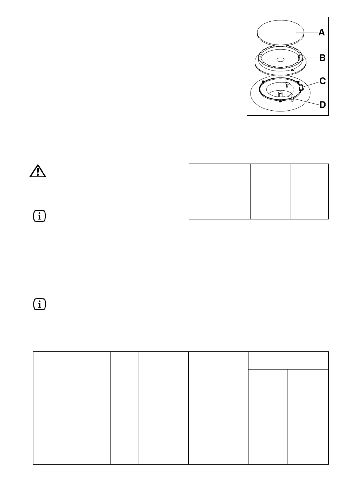
Fig. 1
A - Burner cap
B - Burner crown
C - Ignition candle
D - thermocouple
Burner minimum maximum
diameter diameter
Ultra-rapid
(Triple crown) 180 mm. 260 mm.
Large (rapid) 180 mm. 260 mm.
Medium (semi-rapid) 120 mm. 220 mm.
Small (Auxiliary) 80 mm. 160 mm.
The Hob Broiler (mod. ZGF 991)
The appliance is supplied with an electric broiler situated
in the central zone of the hob.
To switch on the broiler, turn the relevant control knob to
the required heat setting. The control knob is numbered
0 (OFF) - 8 (Maximum).
The broiler may smoke a little and produce a
slightly unpleasant odour when used for the first
time. This is quite normal and will disappear after
a few minutes.
Preheat the broiler on a full setting for 15 minutes, then
adjust the heat setting as desired.
Type of food Quantity Pieces Temperature Pre-heat Cooking time
Gr. Setting minutes (in minutes)
Sausages 500 c.ca 6 4 15 8-10 6-8
Pork
chops 400 c.ca 4 6 10 5-6 5-6
Bacon 400 c.ca 4 4 15 4-5 4-5
Aubergine - - 6 10 6-7 5-6
Peperoni -- 6 10 7-8 6-7
Zucchini -- 4 10 4-5 3-4
Chicory - - 4 10 4-5 3-4
Polenta 500 - 6 15 8-10 6-8
Stale bread - 6 slices 6 10 6-7 5-6
Dry bread - 6 slices 6 10 5-6 3-4
Suggestions for the correct setting of the broiler are given
in the table below. The settings and cooking times are
intended as a guide only. It may be necessary to increase
or decrease the temperatures to suit individual
preferences and requirements. When cooking fat foods
(bacon, sausages, etc.) it is recommended to use
intermediate settings in order to avoid smoke.After
switching off the broiler, especially after long cooking
sessions, its front part will remain hot for at least 45
minutes. Always use oven gloves to remove and replace
food on the broiler.
Upper side
Lower side
4
Page 5

Using the Wok Stand (mod. ZGF 981)
A wok stand is provided to enable you to use a round
bottomed wok on the hob. The wok stand must only be
used on the triple crown burner, and should not be used
with any other type of wok or pan.
When fitting the wok stand, ensure the recesses in the
frame fit securely onto the bars of the pan supports, as
shown in the diagram.
Maintenance and Cleaning
Before any maintenance or cleaning can be carried
out, you must DISCONNECT the hob from the
electricity supply.
The hob is best cleaned whilst it is still warm, as
spillage can be removed more easily than if it is
left to cool.
The Hob Top
Regularly wipe over the hob top using a soft cloth well
wrung out in warm water to which a little washing up liquid
has been added. Avoid the use of the following:
- household detergent and bleaches;
- impregnated pads unsuitable for non-stick saucepans;
- steel wool pads;
- bath/sink stain removers.
Should the hob top become heavily soiled, it is
recommended that a cleaning product such as Hob Brite
or Bar Keepers Friend is used.
The Burners
The burner caps and crowns can be removed for cleaning.
Wash the burner caps and crowns using hot soapy water,
and remove marks with a mild paste cleaner. A well
moistened soap impregnated steel wool pad can be used
with caution, if the marks are particularly difficult to
remove.
After cleaning, be sure to wipe dry with a soft cloth.
Ignition candle
The electric ignition is obtained through a ceramic
"candle" and a metal electrode (Fig. 1 - letter C). Keep
these components well clean, to avoid difficult lighting,
and check that the burner crown holes are not
obstructed.
The electric broiler (mod. ZGF 991)
Always clean the hob broiler after it has cooled down
using a soft cloth well wrung out in warm water.
Dry the broiler before using it. From time to time it will be
necessary to oil the broiler when it is still warm, using a
little vaseline or food oil.
Important! For the proper functioning of the broiler, refit
its screen (as shown in the relevant diagramm).
5
Page 6

Wok Stand (mod. ZGF 981)
The Wok Stand is dishwasher proof. If washing it by hand,
take care when drying it as the enamelling process
occasionally leaves rough edges. If necessay, remove
stubborn stains using a paste cleaner.
Cast Iron Pan Supports
The hob has cast iron pan supports.
Take care when removing them. They are fair heavy and
could damage the hob or your kitchen furniture if you let
them fall down.
To keep the pan supports in the correct position, they
are hooked into hinges at the back of the hob. When
removing the pan supports, lift them up as shown in the
diagram (Fig. 2). Never turn the pan supports on the
hinges, this could damage them.
Wash the pan supports using hot soapy water. If
necessary, a paste cleaner or a soap impregnated steel
wool pad can be used with caution.
YES
NO
Fig. 2
Something Not Working?
If the hob is not working correctly, please carry out the following checks before contacting your local Service Force
Centre.
SYMPTOM
n There is no spark when lighting the gas
n The gas ring burns unevenly
SOLUTION
u Check that the unit is plugged in and the electrical
supply is switched on
u Check that the RCCB has not tripped (if fitted)
u Check the mains fuse has not blown
u Check the burner cap and crown have been
replaced correctly, e.g. after cleaning.
u Check the main jet is not blocked and the burner
crown is clear of food particles.
u Check the burner cap and crown have been
replaced correctly, e.g. after cleaning.
In the event of your appliance requiring service, or if you
wish to purchase spare parts, please contact your
Service Centre.
For your nearest Authorised Service Centre please
contact:
Electric Blue Service & Installation P/L
324 Frankston Dandenong Rd,
Dandenong. VIC 3175
Phone: 1300 654 488
6
Page 7

Instructions for the Installer
Engineers technical data
OVERALL DIMENSIONS
Width: 860 mm.
Depth: 510 mm.
CUT OUT DIMENSIONS
Width: 830 mm.
Depth: 480 mm.
SUPPLY CONNECTIONS
Gas:
RC 1/2 inch (1/2 inch male) Rear right hand corner
Electric: 230-240V 50Hz supply
Electric Broiler 1,05 kW
TYPE TYPE NOZZLE NOMINAL NOMINAL
OF GAS OF BURNER MARKS GAS PRESSURE
1/100 mm CONSUMPTION kPa
Gas burners position
Semi rapid gas burner Rear left and rear right
Auxiliary gas burner Front left
Rapid gas burner Front right
Triple crown gas burner Central
APPLIANCE GAS SUPPLY: Natural gas 1.0 kPa
MJ/h
U-LPG 2.75 kPa
Triple Crown 1.57 13.00
NATURAL
GAS
U-LPG
Burner Dia. Tap By-pass
Auxiliary 28
Semi-rapid 35
Rapid 42
Triple crown 42
Aeration adjustment none
Rapid (large) 1.50 11.00
Semi-rapid (medium) 1.11 6.80 1.00
Auxiliary (small) 0.89 3.80
Triple Crown 0.97 13.00
Rapid (large) 0.93 11.00
Semi-rapid (medium) 0.71 6.30 2.75
Auxiliary (small) 0.55 3.80
1/100 mm
7
Page 8

Important safety requirements
Important
This cooker must be installed by qualified personnel.
The manufacturer will not accept liability, should the above
instructions or any of the other safety instructions
incorporated in this book be ignored.
Regulations
This appliance shall be installed in accordance with the
manufacturers installation instructions, local gas fitting
regulations, municipal building codes, AS5601 (AG601)
and any other relevant statutory regulations.
Data label
The data label is located centrally on the back frame of
the appliance. This appliance is suitable for Natural or
Universal LPG. Ensure that the gas supply matches the
data label. A duplicate of the data label is supplied in the
packaging of the user manual and must be attached to
readily accessible adjacent surfaces of the appliance.
Ventilation
Ventilation must be in accordance with AS5601 (AG601)
Installation Code. In general, the appliance should have
adequate ventilation for complete combustion of gas,
proper flueing and to maintain temperature of immediate
surroundings within safe limits.
the appliance.
Natual gas appliances must be fitted with a pressure
regulator and be installed at the inlet connection. The
gas pressure must then be set as a part of the
commissioning procedures.
For U-LPG the pressure adjustment is made via the
regulator fitted at the domestic cylinder. The natural gas
regulator and U-LPG pressure test point must be
accessible with the appliance installed.
Location
Choose a location free of draughts and open doors and
clear of combustible materials or other fire hazards such
as curtains, etc. The location should ensure convenience
of operation and service. Any adjacent wall surface
situated within 200mm from the edge of any hob burner
and above the height of the hob must be a suitable noncombustible material for a height of 150 mm for the entire
depth and width of the cooker.
Any combustible material above the hotplate must be at
least 650 mm above the top of the hob and no
construction shall be within 450 mm above the top of the
burner.
A minimum distance of 100 mm. must be left between
the side edges of the hob and any adjacent cabinets or
walls.
Connection to the gas supply
Gas connection must be carried out in conformity with
the regulations in force. The appliance leaves the factory
tested and regulated for the type of gas indicated on the
plate which is situated in the lower position near the gas
connection tube. Ascertain that the type of gas with which
the appliance will be supplied is the same as that indicated
on the plate.
If different carry out all the operations according to the
indications cited in the paragraph adaption to different
types of gas.
For a maximum output and minimum consumption
ascertain that the pressure of the gas used has the values
indicated in the table of burner characteristics.
The joint is mounted on the intake area of the pipe, fitted
with a filleted nut G 1/2, between the sealing components.
Screw the parts without forcing, turn the joint in the
direction required and then tighten everything.
Connection
Carry out the connection to the gas plant only by means
of a rigid metallic pipe conforming to the regulations
in force. This appliance is not suitable for connection with
a hose assembly.
The joint for the entry of gas into the appliance is threaded
R 1/2 tapered.
Carry out the connection avoiding any type of stress on
Important
Upon completion of installation, always check:
l that all the joints are completely sealed by using a
soapy solution, never a flame;
l that the gas pressure has been regulated to 1.00kPa
for Natural Gas and 2.75kPa for Universal-LPG. The
pressure test point is located on the regulator for
Natural Gas models or at the top left hand rear of the
cooker for U-LPG models. The pressure should be
measured and adjusted with the Wok burner on high
flame;
l that the automatic ignition system is operating
satisfactory on all burners, both individually and in
combination;
l that the burners operate correctly, are stable, without
yellow tipping or excessive noise on high and low
flame.
Then demonstrate to the customer the appliance
operation and leave these instructions.
A) Ramp with ending nut
B) Seal
C ) Adjustable connection
8
FO 2365
Fig. 3
Page 9

Electrical connections
The appliance is designed to be connected to 230-240 V
monophase electricity supply.
The connection must be carried out in compliance with
the laws and regulations in force.
Before the appliance is connected:
1) check that the main fuse and the domestic installation
can support the load (see the rating label);
2) check that the power supply is properly earthed in
compliance with the current rules;
3) check the socket or the double pole switch used for
the electrical connection can be easily reached with
the appliance built in the furniture unit.
The appliance is supplied with a connection cable provided
with a plug, able to support the load marked on the
identification plate. The plug has to be fitted in a proper
socket.
If connecting the appliance directly to the electric system,
it is necessary that you install a double pole switch
between the appliance and the electricity supply, with a
minimum gap of 3 mm. between the switch contacts
and of a type suitable for the required load in compliance
with the current rules.
The connection cable has to be placed in order that, in
each part, it cannot reach a temperature 50 °C higher
than the room temperature.
The brown coloured phase cable (fitted in the terminal
block contact marked with "L") must always be connected
to the network phase.
Adaptation to different types of gas
WARNING: Servicing shall only be carried out
by authorised personnel.
Substitution of the nozzles
- Remove all pan supports, burner caps, rings and
crowns;
- With a tubular spanner no. 7 unscrew and remove
(see diagram) the nozzles substituting them with those
corresponding to the type of gas used (see Technical
data);
- Remount the parts carrying out the operations
described in reverse. Upon completion remove
existing gas type label and stick the relevant gas type
label near the gas supply pipe.
If the pressure of gas used is different (or variable) from
that foreseen an appropriate pressure regulator should
be installed on the entry tube. In case pressure regulators
for U-LPG are used these should conform to the
regulations in force.
Regulation of the minimum
To regulate the minimum:
- bring the tap to the minimum flame position.
- extract the knob.
- in case of conversion from natural gas to U-LPG, tightly
screw the by-pass screw (see diagram);
- when converting from U-LPG to natural gas unscrew
about ½ turn by-pass screw, until a regular small flame
is reached.
Finally check that by quickly turning the tap from the
maximum position to the minimum position the burner
is not extinguished; remount the parts carrying out
the operations described in reverse.
FO 0392
By pass screw
9
Page 10

Building In
Rectangular cut-out size for hob
FO 2349
860
510
Fig. 4
These hobs can be inserted in a built-in kitchen unit whose
depth is between 550 and 600 mm. The hobs dimensions
are shown in Fig. 4.
Cut Out Size
The dimensions of the cut-out are given in the diagram.
55 min.
480
Dimensions are given in mm.
30
830
38
20
R 60
150 min
Fig. 5
Fitting the Hob into the worktop
Carry out the building in of the hob as follows:
F
put the seals supplied with the hob on the edges of
the cut out, as shown in the diagram, taking care
that the seals meet without overlapping;
place the hob in the cut out, taking care that it is
centred;
fix the hob with the relevant fixing clamps and screws,
as shown in the diagram. When the screws have been
tightened, the excess seal can be removed.
The edge of the hob forms a double seal which prevents
the ingress of liquids.
FO 2348
Fig. 6
Seal
FO 0199
Fig. 7
10
Page 11

Possibilities for
insertion
Kitchen unit with door
Proper arrangements must be taken in
designing the furniture unit, in order to avoid
any contact with the bottom of the hob which
can be heated when it is operated.
The panel below the hob (Fig. 8-a) is essential
to prevent access to the hot hob surface, as
per warning label.
The panel fitted under the hob should be
easily removable to allow an easy access if
a technical assistance intervention is needed.
Kitchen unit with oven
Fig. 8
60
Fig. 9
480
30
30
a
20 min
b
380
591
140
The hob recess dimensions must comply the
indication given in Figs. 9 and 12 and must
be provided with brackets to allow a
continuous supply of air.
To avoid overhating, the building in should be
carried out as shown in Figs. 10 e 11.
The hob's electric connection and the oven's
one must be carried out separately, both for
safety reasons and to allow the oven to be
easily taken off the unit.
Hanging furniture units or hoods must be
placed at 650 mm. minimum from the hob
(Fig. 13).
FO 2044 FO 2043
a) Removable panel
b) Space possibly useful for
connections
Fig. 10
50 cm
360 cm
Fig. 11
2
2
120 cm
180 cm
2
2
Fig. 12
FO 0198
560 min.
550 min.
FO 2041
FO 2042
Fig. 13
650 min
FO 2350
11
Page 12

Grafiche MDM - Forlì
From the Electrolux Group. The worlds No.1 choice.
The Electrolux Group is the worlds largest producer of powered appliances for kitchen, cleaning and outdoor use. More than
55 million Electrolux Group products (such as refrigerators, cookers, washing machines, vacuum cleaners, chain saws and
lawn mowers) are sold each year to a value of approx. USD 14 billion in more than 150 countries around the world.
35677-7502 01/03
 Loading...