

Page 1

INSTRUCTIONS FOR THE USE AND CARE
MIXED FUEL
GB
ZANUSSI
COOKER
ZCM 5200 W
ZCM 5200 B
Appliances class 2 sub class 1 and class 1
2
Page 2

WARNINGS
It is most important that this instruction book should be retained with the appliance for future
reference. Should the appliance be sold or transferred to another owner, or should you move
house and leave the appliance, always ensure that the book is supplied with the appliance in
order that the new owner can be acquainted with the functioning of the appliance and the
relevant warnings.
THESE WARNINGS ARE PROVIDED IN THE INTEREST OF SAFETY. YOU MUST READ THEM
CAREFULLY BEFORE INSTALLING OR USING THE APPLIANCE.
This appliance is designed to be operated by adults.
Children should not be allowed to tamper with the
controls or play with the product.
This appliance is heavy and care must be taken when
moving it.
Any installation work must be undertaken by a
competent, authorised installer in accordance with the
Gas Safety (Installation and Use) Regulations 1984
and the relevant codes of practice.
In the UK, C.O.R.G.I. registered installers (including
regions of British Gas) undertake the work to safe and
satisfactory standards.
Any electrical work required to install the appliance
should be carried out by a qualified or competent
person.
It is dangerous to alter the specifications or modify the
product in any way.
This appliance should be serviced by an authorised
Zanussi Network Service Centre, and only genuine
Zanussi spare parts should be used.
Cookers become very hot with use, and retain their
heat for a long period after use. Children should be
supervised at all times and should not be allowed to
touch the hot surfaces or be in the vicinity when in use
or until the appliance has cooled after use.
Always ensure that the control knobs are in the "off"
position when not in use.
The lid is designed as a dust cover when closed, and
as a splash-back when open. Do not use for any other
purpose.
After using the cooker, the glass lid fitted MUST NOT
be closed until the hob and oven are completely cold.
If you lower the glass lid when the hob or oven are still
hot or warm, the glass may shatter and could cause
injury.
Always remove any spillage from the surface of the
cover before removal or opening (if applicable), and
the appliance should be allowed to cool before
replacing or closing the cover.
For hygiene and safety reasons, this appliance should
be kept clean at all times. A build-up of fats or
foodstuffs could result in a fire.
This appliance has been designed for cooking edible
foodstuffs only, and must not be used for any other
purposes.
Never line any part of the oven with aluminium foil.
Unstable or misshapen pans should not be used on
the burner as unstable pans can cause an accident by
tipping or spillage.
Easy clean liners should never be cleaned with any
other than detergent water (see Cleaning Instructions).
Before any maintenance or cleaning work is carried
out on the appliance, always take out the plug from the
wall socket.
Ensure that the oven shelves are put in place in the
correct way (see instructions).
All gas appliances require adequate ventilation. Failure
to provide this could result in a lack of oxygen. Your
installer will advise if in doubt.
Always ensure that the oven vent which is located at
the centre back of the hob is left unobstructed to
ensure ventilation of the oven cavity.
The storage drawer located beneath the oven may
become hot whilst the oven is in use, only oven-proof
dishes should be stored in the drawer and care should
be taken when removing any items. Do not store
combustible materials in the drawer.
Under no circumstances should you attempt to repair
the appliance yourself. Repairs carried out by
inexperienced persons may cause injury or more
serious malfunctioning. Refer to your local Zanussi
Service Centre. Always insist on genuine Zanussi
spare parts.
Read the Instruction book before installing and using
the appliance.
3
Page 3

CONTENTS
Installation Page 4
Technical Data Page 5
Use and Care Page 5-6
Use and Operation Page 7
Cooking Chart Page 10
Electronic Minute Minder Page 13-14
Maintenance and Cleaning Page 15
Removing the Oven Door Page 17
Oven lamp replacement Page 17
What Happens if Something Goes Wrong Page 18
Zanussi Guarantee Conditions Page 19
Warning
Please remember that an appliance used for cooking
does get hot, so make sure that children are kept
well away.
Important
Where the cooker is fitted with a lid, the lid must be
completely raised before the cooker will function.
Note:
If you require service, you must quote the model
number (see front cover), and the serial number,
refer to your supplier or local Zanussi Service Force
Centre.
This appliance complies with the following E.E.C. Directives:
• 73/23 - 90/683 (Low Voltage Directive);
• 89/336 (Electromagnetical Compatibility Directive);
• 90/396 (Gas Appliances Directive);
• 93/68 (General Directives)
and subsequent modifications.
CLASS APPLIANCE: 2 sub class 1 and class 1
APPLIANCE CATEGORY: I 2H
APPLIANCE GAS SUPPLY: Natural gas G20 20mbar
These instructions are only for the countries stated by the nation
mark printed on the front cover of this instruction book.
INSTALLATION
It is mandatory that all operations required for the
installation be carried out by a Competent Gas
Installer (Corgi registered installers normally meet
this criteria), and in accordance with existing rules
and regulations.
The relevant instructions are to be found in the
separate installation manual.
Please ensure that when the appliance is installed, it
is easily accessible for the engineer in the event of a
breakdown.
WARNING:
THIS APPLIANCE MUST BE EARTHED.
When the appliance is first installed
Once the oven has been installed, it is important to
remove the protective materials, which were put on in
the factory.
Before using your oven
Switch the oven to MAX. and leave it to run empty,
for 30 minutes to remove any unpleasant new smells.
4
Page 4

TECHNICAL DATA
Model Number: ZCM 5200 W
ZCM 5200 B
Dimensions
Height 900 mm
Depth 595 mm
Width 597 mm
Oven Capacity 1.9 Cu. ft
Hob
Rear left heat area (N) 2,0 kW
Front left heat area (R) 3,0 kW
Rear right heat area (N) 2,0 kW
Front right heat area (S) 1,0 kW
N = Normal burner
R = Rapid burner
S = Simmer burner
BURNER RAPID NORMAL SIMMER
GAS
TYPE OF
CHARACTERISTICS
3
POSITION MAX MIN MAX MIN MAX MIN
NOMINAL THERMAL
POWER kW 3,0 0,65 2,0 0,45 1,05 0,33
Oven
Traditional oven element rating 1880 W
Grill element rating 1830 W
Double grill element rating 2665 W
Convection oven element rating 2090 W
Oven lamp 15 W
Convection fan rating 30 W
Maximum power absorbed 2680 W
Power supply (50 Hz) 230-240 V
Total appliance rating (gas + electric) 10,68 kW
NOMINAL FLOW
20 mbar
NATURAL GAS
POWER lt/h 15°C 286 57 190 38 95 28
GROSS HEAT
NOZZLE REFERENCE 119 Adjusted 96 Adjusted 70 Adjusted
VALUE 37.78 MJ/ m
1/100 mm
COOKER FEATURES
A. Glass lid
B. Safety cut-off
C. Semi-Rapid burner
D. Rapid burner
E. Control panel
F. Shelf support
G. Shelves
H. Oven door
I. Removable drawer
J. Front panel
K. Base
L. Baking tray
M. Auxiliary burner
N. Semi-Rapid burner
0
A
B
C
D
SET
TIME
E
F
G
H
I
J
STOP
ZANUSSI
ZCM 5200
N
M
L
K
5
Page 5

STOP
SET
TIME
PUSH
BOTH
-
+
STOP
SET
TIME
PUSH
BOTH
-
+
0
100
150
200
50
CONTROL PANEL
2
1
1. Electronic Minute Minder
2. Thermostat control light
3. Ignition button
4. Mains-on light
5. Oven selector knob
6. Oven thermostat knob
7. Semi-rapid burner knob
8. Rapid burner knob
9. Auxiliary burner knob
10. Semi-rapid burner knob
O. Grill/roasting pan, large
P. Reversible grill trivet
Q. Removable handles (2)
4
10987653
O
P
Q
OVEN
6
R
S
T
U
V
R. Grill
S. Oven light
T. Fan
U. Filter
V. Oven liners
Page 6
OPERATION
Safety cut off
Your cooker is fitted with a safety cut off device
which is actuated when the lid is lowered. This cuts
the electricity and gas supply to the whole appliance,
and prevents the lid being lowered onto the burners
when they are still on. When the lid is raised again,
the electricity supply to the oven is automatically
restored. The gas supply to the hob must be restored
manually by depressing the pushbutton on the rear
left hand corner of the hob surface.
There are two important points to remember; firstly
the lid must be in the raised position for any part of
the cooker to function. Secondly, you must
remember to return all the controls to their off
positions when you have finished using the cooker. If
you have for instance left the oven on, when the lid is
raised it will automatically come on again.
Obviously if you manually restore the gas supply and
of the burner controls have not been returned to their
off positions, the gas will escape.
Safety cut off switch
Important
Be very careful when frying food in hot oil or fat as the
overheated splashes could easily flare up.
NOTE: "the use of a gas cooker produces heat and
damp in the room where it is installed. Ensure a good
airing of the room keeping the natural ventilation
holes open or installing an aspiration hood with
exhaust pipe".
NOTE: "A long and intensive use of the machinery
can require further airing, for example the opening of
a window, or a more efficient ventilation, increasing
the mechanic suction power, when existing".
Do not tamper with or attempt to adjust the safety
cut-off switch. Any adjustment must be made by a
qualified engineer.
The switch is designed to prevent the hob or oven
being turned on when the lid is closed.
Tampering with the switch may enable the heat to be
turned on with the glass lid in the down position. The
heat would cause the glass lid to shatter which could
result in injury. Should you find the switch not
functioning correctly, contact your local authorised
Zanussi Service Centre.
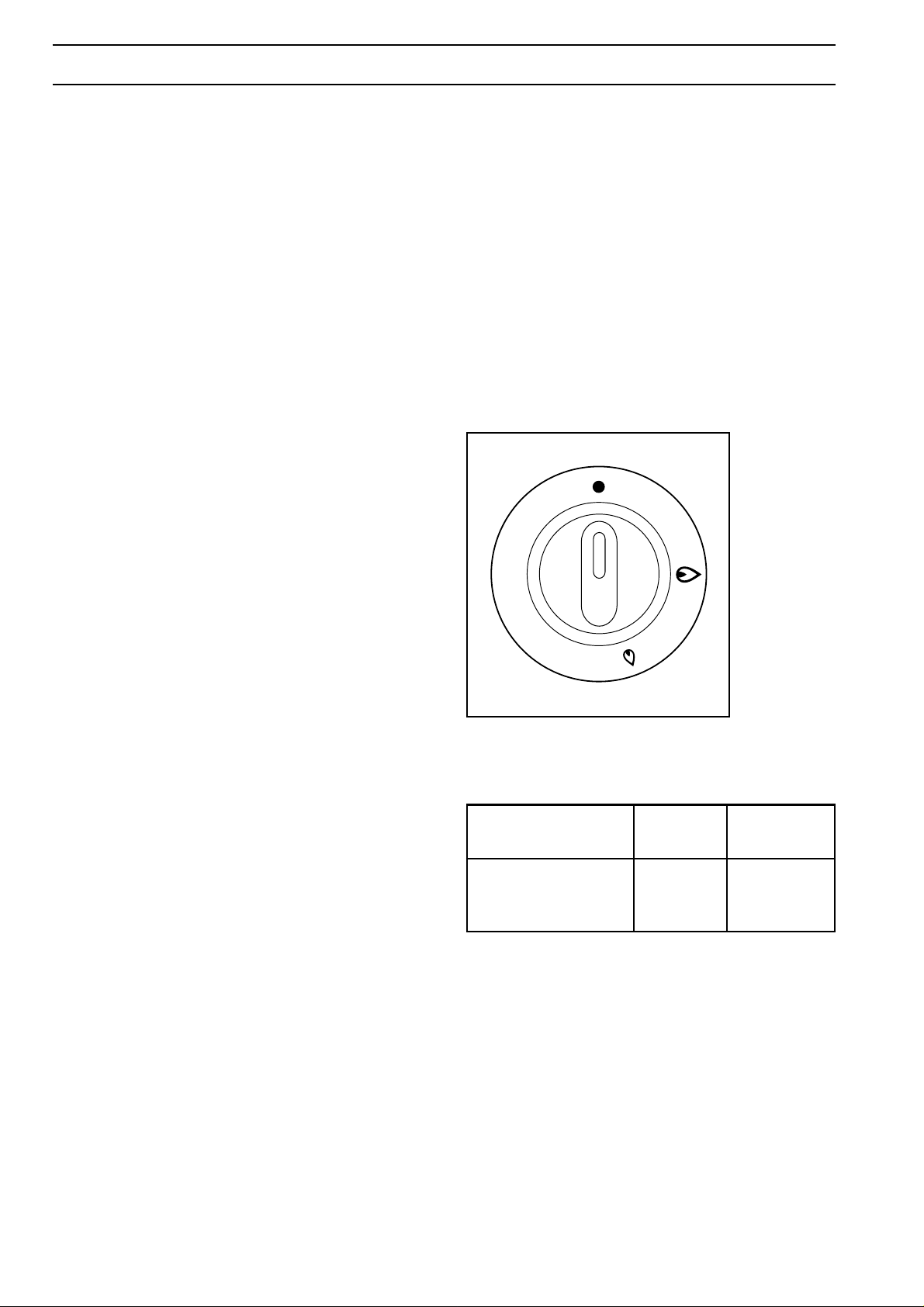
HOB BURNERS (Fig. 1)
The control panel incorporates knobs to operate the
four gas burners.
To light a worktop burner, turn the relevant knob (Fig.
1) to the large flame symbol which corresponds to
the maximum setting.
Depress the ignition pushbutton on the fascia panel.
Once the burner is alight adjust the flame as
required. The smaller flame symbol is a simmer
setting.
It is important that pans with a base fitting the size of
the burner be used so that the flame does not spread
beyond the bottom of the pan.
NOTE:
"In case of accidental extinction of the burner flames,
turn the handle control off and do not try to turn it on
unless at least 1 minute has elapsed".
FO 0839
Table of containers to be used
(flat bottom only)
Burner Ø Min. Ø Max
(mm) (mm)
Rapid 160 260
S/Rapid 120 220
Auxiliary 80 160
Fig. 1
MULTIFUNCTION OVEN
The multifunction oven makes it possible to carry out
various types of cooking, depending on the nature of
the food and its volume.
All cooking must be done with the oven door closed.
The oven light remains on with all cooking functions.
The oven control knob symbols are listed together
with a brief description of the functions (a more
detailed explanation of the functions and how to use
them are given in the "ZANUSSI COOKBOOK"
book).
7
Page 7

Oven control knob (Fig. 2)
By turning this control knob, you can select any of
the following functions:
Oven light, this will come on whenever the oven
is in use.
Traditional cooking, uses the top and bottom
element for single shelf cooking; this function will
enable you to use your favourite recipes without
having to adapt the temperatures. It is necessary
to pre-heat the oven in this instance.
Top oven element only, enables you to finish off
dishes on the top only.
Bottom oven element only, enables you to finish
off dishes on the bottom only.
0
FO 0876
Thermostat control knob (Fig. 3)
Fig. 2
Economy grill, inner grill element only.
Inner and outer grill elements.
Thermal grilling, gives a spit roast effect to all
joints. Using this system eliminates the need to
turn food during cooking, although large food
items may require to be turned half way through
the cooking time.
Select a max-temperature of 200°C.
Note: The grill cannot be used at the same time as
the oven.
Caution
The appliance must never be left unattended whilst
grilling.
Cuisinair cooking, this fan ducted system will
allow you to roast or bake at the same time with
very little flavour transference, and on any shelf.
For this function the circular element and fan
behind the back wall of the oven are used.
By turning the thermostat control knob clockwise, you
select the cooking temperature. The temperature
selection starts at 50°C and is marked in 10°C
increments up to maximum, where the temperature
at the centre of the centre of the oven will reach
approximately 250°C. The thermostat controlling the
temperature is totally variable so it is possible to
select temperatures between those marked. The
MAX. setting is particularly suitable for grilling. Once
the oven temperature has been selected, the
temperature light will come on and remain on until
the oven has reached the correct temperature; after
that, it will come on and off with the thermostat
showing how the temperature is being maintained.
During cooking the oven door should be opened as
little as possible to avoid heat loss and so excessive
electricity consumption.
50
Defrost setting (N.B.: This is NOT a cooking
position). This position is intended to assist
thawing of frozen foods.
Caution
Do not place pans, dripping pans, biscuit pans or
aluminium foil on the oven bottom. This could cause
a heath build-up which would affect the baking
results and damage oven enamel.
8
FO 0877
100
200
150
Fig. 3
Page 8

Safety thermostat
Grease filter
Should the main oven thermostat fail, the oven is
protected by a safety thermostat which will operate if
the temperature within the oven reaches too high a
level. Once the temperature has returned to a safe
level, the safety thermostat will switch back on and
the oven will re-start. In cases where is a permanent
failure it is necessary to contact the Zanussi Network
Engineer.
USING THE GRILL
To switch on the grill, turn the oven control knob to
either or symbol, then turn the thermostat knob
to the required temperature setting.
Turning the oven control knob to the symbol
operates the inner element only, when the oven
control knob is turned to the symbol both the inner
and outer elements operate, the latter provides a
larger grilling area.
This is known as a dual element.
Foods to be grilled should be placed on the wire
trivet in the grill pan, the trivet can be positioned
either way up to give the required distance from the
element.
Caution
When roasting meat, be sure to install the special
grease filter to protect the fan in the rear wall of the
oven from fat splashes.
After roasting is completed, remove the grease filter
and clean thoroughly with warm detergent water. As
it is stainless steel you can safely wash it in the
dishwasher.
To remove the grease filter, pull up the protruding
tongue and then pull the filter outwards removing it
from the rear panel (Fig. 5).
To replace the filter, hold the protruding tongue and
slide down onto the slots in the rear wall of the oven
so that it clips on.
Storage drawer
The storage drawer is located underneath the oven
cavity.
During cooking the storage drawer may become hot
if the oven is on high for a long period of time,
therefore flammable materials such as oven gloves,
tea towels, plastic aprons etc. should not be stored in
the drawer.
Oven accessories such as baking sheets, will also
become hot; therefore care should be taken when
removing these items from the drawer when the oven
is in use or still hot.
The appliance must never be left unattended whilst
grilling.
Note:
We recommend that you wipe fat splashes off the
grill element when it is cold in order to prevent
smoking from the fat as it burns off when the grill is
next used.
Important
Your oven door is fitted with hinges, giving two door
positions, fully open or fully closed.
When grilling, the oven door must be closed.
Grilling with the door open could cause areas of the
oven to become excessively hot as well as reducing
the performance, efficiency and economy of the grill.
Shelves and runners
This Zanussi cooker has four shelf positions. The
anti-tip feature is achieved by the closeness of the
shelf runners. The auto-stop feature is achieved by
two metal stops fixed to the shelves, as the shelf is
moved in and out, the metal stops catch on the
bottom of any pair of shelf runners, if the shelf is
wrongly positioned these stops will not catch,
therefore it is important to position the shelves as
shown in Fig. 4.
FO 0336
4
3
2
1
Fig. 4
FO 0018
Fig. 5
9
Page 9

OVEN COOKING CHART
Food to be cooked Quantity Recommended Temperature Time in
kg level (starting °C minutes
from bottom)
Cakes
* Mixture in mould 1 2 (1and3) 190 170 20-60
* Puff pastry, base 2 2 (1and3) 200 180 30
* Mixture with rising agent 1 2 (1and3) 190 170 50-60
* Small cakes 2 2 (1and 3) 180 160 20-30
* Victoria sandwich 2 2 (1and3) 180 170 25-35
* Scones 2 2 (1and3) 220 200 10-20
* Bread 1 2 200 180 40-60
Meat
Veal 1 1 or 2 2 200 180 60-80
Beef 1 1 or 2 2 200 180 70-80
Pork 1 1 or 2 2 200 180 70-90
Chicken 1-1,5 1 or 2 2 200 180 60-90
Chopped turkey 1,5 1 or 2 2 200 180 120-140
Duck 1-1,5 1 or 2 2 200 180 120-140
Stews
Beef stew 1 1 2 180 160 120-140
Veal stew 1 1 2 180 160 110-130
Fish
Dried cod, cod, sole 1 2 2 (1and3) 200 180 20-30
Wrasse, sargo 1 2 2 (1and3) 200 180 40-60
Oysters - 2 2 (1and3) 200 180 20-30
* Soufflè (sweet or savory) 0,75 1 2 200 180 40-60
* Pizza 0,5 1 2 (1 and3) 240 220 20-30
Notes
1. For the items marked with an asterisk (*) the oven must be preheated.
2. When cooking in different positions, the levels indicated (in the table are recommended).
3. Times refer to when cooking in one position only. When cooking in more than one position at a time, increase cooking time by 5-10
minutes.
4. When cooking roasts of beef, veal, pork or duck which have been rolled or contain bones, eventually increase cooking time by 20
minutes.
FO 0018
10
4
3
2
1
Page 10

GRILL, ECONOMY GRILL
TEMPERATURE SELECTION
Important
All grilling must be carried out with the oven door
closed and the grill pan handle removed from the
pan.
Most foods should be placed on the grid in the grill
pan to allow maximum circulation of air to lift the food
out of the fats and juices. Food such as fish, liver and
kidneys may be placed directly on the grill pan, if
preferred
Adjust the grid and grill pan runner position to allow
for different thicknesses of food. Position the food
close to the element for faster cooking and further
away for more gentle cooking
Food should be thoroughly dried before grilling to
minimise splashing. Brush lean meats and fish lightly
with a little oil or melted butter to keep them moist
during cooking
Accompaniments such as tomatoes and mushrooms
may be placed underneath the grid when grilling
meats
When toasting bread, we suggest that the top runner
position is used with the grid in its 'high' position
Preheat the grill on a full setting for a few minutes
before sealing steaks or toasting. Adjust the heat
setting and the shelf as necessary, during cooking
The food should be turned over during cooking, as
required.
NOTE:
For safety in use, the grill element is controlled
by the thermostat. During cooking, the grill
cycles on and off to prevent overheating.
GRILL - ECONOMY GRILL
gr.
QUANTITY
800 4
PIECES
TYPE OF COOKING
pre-heat
minutes
shelf
4
3
2
1
Temp.
°C
upper
cooking time
Beef fillets - 4 Max 8-10 4-6
600 4 Pork chops - 4 Max 8-10 5-8
800 8 Spare ribs - 4 Max 6-8 4-6
500 8 Sausages - 4 Max 8-10 4-6
700 4 Kebabs - 4 Max 10-12 5-7
500 4 Chicken breasts - 4 Max 10-12 5-7
500 6 Sole - 4 Max 6-8 4-6
6 Toast bread - 4 Max 3-4 1-2
lower
The times quoted above are given as a guide and should be adjusted to suit personal taste.
11
Page 11

THERMAL GRILLING
Use of thermal grilling
Thermal grilling offers an alternative method of
cooking food items normally associated with
conventional grilling.
The grill element and the oven fan operate
alternately, circulating hot air around the food. The
need to check and turn food is reduced. Thermal
grilling helps to minimise cooking smells in the
kitchen and allows you to grill with the oven door
closed. With the exception of toast and rare steaks,
you can thermal grill all the foods you would normally
cook under a conventional grill.
The lower part of the oven can be used to cook
accompaniments at the same time, e.g. tomatoes
and mushrooms with a mixed grill or breakfast.
Dishes prepared in advance such as shepherd's pie,
lasagne and au gratins can be heated through and
browned on the top using the thermal grilling
function.
NOTE:
Thermal grilling helps to minimise cooking smells in
the kitchen and is carried out with the main oven
door closed, and with the grill pan handle removed.
THERMAL GRILLING
It is advisable not to select temperatures over 200°C
gr.
QUANTITY
1000 2
PIECES
TYPE OF COOKING
pre-heat
minutes
Beef
Rolled joints - 3 180 30-40 20-30
{
Lamb
Pork
shelf
4
3
2
1
Temp.
°C
upper
cooking time
lower
800 4 Quartered chicken - 3 200 25-30 15-20
1000 2 Chickens - 3 190 30-35 25-30
800 1 Guinea fowl - 2 180 35-40 30-35
500 2 Pigeons - 3 180 35-40 30-35
500 4 Quail - 3 200 25-30 20-2
Vegetable gratin - 3 200 15-25 4 Toasted sandwiches - 3 200 3-5 1-2
9 St. Jacques shells - 3 200 15-20 -
600 2 Mackerel - 3 200 10-20 6-8
800 4 Fish slices - 3 200 10-15 8-10
The times quoted above are given as a guide and should be adjusted to suit personal taste.
12
Page 12

ELECTRONIC MINUTE MINDERELECTRONIC MINUTE MINDER
STOP
SET
TIME
PUSH
BOTH
-
+
STOP
SET
TIME
PUSH
BOTH
-
+
STOP
SET
TIME
PUSH
BOTH
-
+
STOP
SET
TIME
PUSH
BOTH
-
+
STOP
SET
TIME
PUSH
BOTH
-
+
STOP
SET
TIME
PUSH
BOTH
-
+
12
1. ( - ) Decrease control & minute minder
setting button
2. ( + ) Increase control
( ) Cookpot symbol
( ) PUSH BOTH CLOCK SETTING
SYMBOL
1. Set the time of day
When the electricity supply is first switched ON, the
display will flash 0.00. See Fig. 6.1.
Press buttons (1) and (2) together. The display will
momentarili read 88.88. See Fig. 6.2. Release buttons ,
0.00 will appear in the display as Fig. 6.3. Within 5
seconds press button (2), 12.00 will show in the displa y
as Fig. 6.4.
Within 5 seconds, press and hold either button (1) to
decrease or button (2) to increase the time until the
correct time of day on the 24 hour clock is reached, e.g.
14.30. See Fig. 6.5.
Note
The increase and decrease control buttons
operate slowly at first and then more
rapidly . They should be pressed separately .
Fig. 6.1
Fig. 6.2
Fig. 6.3
Fig. 6.4
Fig. 6.5
13
Page 13

STOP
SET
TIME
PUSH
BOTH
-
+
STOP
SET
TIME
PUSH
BOTH
-
+
STOP
SET
TIME
PUSH
BOTH
-
+
STOP
SET
TIME
PUSH
BOTH
-
+
STOP
SET
TIME
PUSH
BOTH
-
+
STOP
SET
TIME
PUSH
BOTH
-
+
STOP
SET
TIME
PUSH
BOTH
-
+
2. The minute minder
IMPORTANT
The minute minder can be used to time a set cooking
period. At the end of the cook time the minute minder
will automatically switch off the oven if in use.
The minute minder gives an audible reminder at the
0 . 00
end of any period of cooking up to 23 hours and 59
minutes.
To set, press button (1) and the display will read
see Fig. 6.6.
Release button (1) and press and hold button (2). The
display will count up in one minute intervals until the
interval to be timed is reached, e.g. 30 minutes, see
Fig. 6.7. If necessary, press and hold button (1) to
achieve the correct time interval.
The minute minder will begin to count down once set.
At the end of the timed period, the minute minder will
click, switching the oven OFF if in use.
An audible signal will sound for up to 2 minutes.
The cookpot symbol will flash and the time of day will
show in the display. See Fig. 6.8.
T o stop the sound press b utton (1). The display will stop
flashing and show the time of day, e.g. 15.00. The
cookpot symbol ( ) will go out. See Fig. 6.9. If using
the oven it will come on again once button (1) has been
depressed. When cooking is complete remove f ood and
turn OFF oven temperature control.
Fig. 6.6
,
Fig. 6.7
Fig. 6.8
3. To cancel the minute minder
Press and release button (1). Then press and hold button
(1) and the display will count down in one minute
intervals to
After a few seconds the cookpot symbol will flash and
the time of day will show in the display. See Fig. 6.11
0 . 00
. See Fig. 6.10. Release button (1).
If the oven is in use this will switch OFF after a few
seconds.
T o reset, press button (1) and (2) together . See Fig. 6.12.
4. Things to note
1. The time of day must be set before the oven will
operate. There will be a few seconds dealy before
the oven switches on.
2. The minute minder function controls the main oven
only and will switch the oven OFF at the end of a
timed period. This function is useful if you want to
begin cooking now and have the oven switch OFF
automatically.
3. If you have used the minute minder to time food
cooking in the oven y ou will need to reset the timer
before the oven can operate again.
Fig. 6.9
Fig. 6.10
Fig. 6.11
14
Fig. 6.12
Page 14

MAINTENANCE AND CLEANING
Cleaning your gas hob
The hob is best cleaned whilst it is still warm, as
spillage can be removed more easily than if it is left
to cool.
The pan supports, burner caps and burner crowns
can be lifted off for cleaning. Use hot detergent water
and remove stubborn marks with a mild, non-scratch
paste cleaner. A well moistened soap impregnated
steel wool pad can be used with caution if the marks
are particularly difficult to remove.
The burner crown may lose its matte surface after
several cleanings, but this will in no way impair its
performance.
After cleaning, be sure to wipe the hob dry with a soft
cloth.
The pan support are dishwasher proof. If washing
them by hand, take care when drying them as the
enamelling process occasionally leaves rough
edges. The supports should be placed correctly on
the hob, if they are incorrectly replaced, they will not
be stable.
Fig. 7
FO 0945
The pan support of this cooker is fitted with antiscratch rubber feet.
These feet are dishwasher proof and should not be
removed when cleaning the pan support.
If the rubber feet become detached from the pan
support re-fit as per diagram Fig. 7.
Anti-scratch rubber feed can be obtained from you
local Zanussi Service Centre for a small charge,
when ordering please quote spare part number
355602301/2.
CLEANING THE OVEN
Oven door
Regularly wipe over the control panel, oven door and
door seal using a soft cloth well wrung out in warm
water to which a little washing up liquid has been
added.
To prevent damaging or weakening the door
glass panels avoid the use of the following:
• Household detergent and bleaches
• Impregnated pads unsuitable for nonstick saucepans
• Brillo/Ajax pads or steel wool pads
• Chemical oven pads or aerosols
• Rust removers
• Bath/Sink stain removers
Clean the outer and inner door glass using warm
soapy water. Should the inner door glass become
heavily soiled it is recommended that a cleaning
product such as Hob Brite, or Bar Keepers Friend is
used.
DO NOT clean the oven door while the
glass panels are warm. If this precaution is
not observed the glass panel may shatter.
If the door glass panel becomes chipped or
has deep scratches, the glass will be
weakened and must be replaced to prevent
the possibility of the panel shattering.
Contact your local Service Centre who will
be pleased to advise further.
Shelves and shelf supports
To clean the chrome parts of the oven, soak in warm
detergent water and remove stubborn marks with a
dampened non-stick pan scourer.
Rinse well and dry with a soft cloth.
Do not use abrasive scourers or steel wool.
15
Page 15

Oven Cavity
The enamelled oven cavity is best cleaned whilst still
warm.
It is preferable/advisable to wipe the oven door with a
soft cloth soaked in warm detergent water, after each
use. However, occasionally, it will be necessary to do
a more thorough cleaning using a proprietary oven
cleaner. Do not use aerosol oven cleaners,
abrasive scourers or steel wool.
'Stay Clean' oven lining
This cooker is fitted with a set of coated liners. These
are known as 'stay clean' or 'easy care'. To obtain
the maximum efficiency from your liners, follow the
guidelines carefully for their use and care.
The linings are coated with a special substance
which helps to clean itself by a process of
oxidazation. Although the linings will not remain
absolutely spotless, they will reduce your oven
cleaning chores considerably when used in the
correct way.
Fig. 8
FO 0145
The linings work most effectively if the splasher are
kept to a minimum, and the soil is not allowed to
build up, as this will retard the cleaning action. If the
oven has been used at low temperatures, it should
be heated for one hour on 200°C.
Never use abrasive scourers, steel wool pads or an
aerosol oven cleaner on the coated linings.
Removing/replacement of the 'stay clean'
oven liner panels
It is not necessary to disconnect the appliance from
the electricity supply when removing the side panels.
However, you must disconnect the electricity supply,
before attempting to remove the back panel, by
turning off at the wall socket or cooker box and
removing the plug from the wall.
Occasionally it will be necessary to remove the oven
liner panels to facilitate oven cleaning. To do the,
proceed as follows:
1. Unscrew the ring nuts, securing the side runners,
and remove the runners (Fig. 8).
Fig. 9
FO 0085
2. Slide the side panels toward yourself to release
them from their retaining pins, then lift away from
the oven wall (Fig. 9).
3. Make sure that the electricity supply to the
appliance is disconnect/ Then using a suitable
Philips screwdriver, unscrew the four fixing screws
on the back panel (Fig. 10). This is a good
opportunity to clean the rear side of the back
panel.
4. To replace the panels, reverse the above
procedure.
16
Fig. 10
FO 0028
Page 16

Removing the oven door (Fig. 11 & 12)
Warning:
It is important that the retaining discs are fully turned
and located as the hinges are under high sprung
tension.
1. Open the door completely so that it is in the
horizontal position.
2. Raise the two bars.
3. Raise the door halfway.
4. At this stage, clasp the two hinges on either side of
the door together simultaneously. The door can
then be removed by pulling on and downwards.,
maintaining the angle.
Replacing the oven door
1. Clasp the two hinges on either side of the door
simultaneously.
2. Hook the top hinge into the top slot, so that the
hook is engages with the roller.
3. Drop the lower hinge into the lower slot, so that the
notch is engaged. Drop the door down so it is in
the horizontal position.
Fig. 11
FO 0417
Note
Is it important when carrying out this operation, that
both hinges be located simultaneously.
4. Turn the bars.
The door can then be closed.
Removal/replacement of the oven lamp (Fig. 13)
Important
Remember to disconnect the electricity supply before
undertaking maintenance of any kind.
Push in and unscrew the glass cap anticlockwise.
Remove the faulty bulb and replace with one that
resists heat to high temperatures (300°C). Electric
bulb 15W - 240V (50Hz), 300°C, E14.
These are available from your local Service Centre.
Fig. 12
FO 0967
Fig. 13
FO 0287
17
Page 17

WHAT HAPPENS IF SOMETHING GOES WRONG
If the appliance fails to operate:
1. If the oven does not come on, check that the
programmer is properly set for manual operation, or
that you have programmed any automatic cooking
correctly.
2. Check that the hob cover, where present, is in the
fully raised position.
3. Check that it is properly plugged in.
4. Check that the socket switch is turned on.
5. Check that the socket is supplying power - do this
by plugging in another appliance that is known to be
working properly.
6. Check that the fuse in the plug is intact.
7. If the hob area does not work, check that you are
turning the correct control knob.
8. Check that you have manually re-set the gas
supply.
IF YOU SUSPECT A GAS LEAK, TURN ALL
CONTROLS TO THEIR OFF POSITIONS, AND
TURN THE MAINS GAS SUPPLY OFF
IMMEDIATELY. THEN CONTACT YOUR GAS
BOARD.
If after all these checks, the oven still does not work,
contact your local Zanussi Service Force Centre.
When you contact them, they will need the following
information:
1. Your name, address and post code.
2. Your telephone number
3. Clear and concise details of the fault
4. The model and the serial number (which can be
found on the rating plate)
5. Date of purchase
Please note that it will be necessary to provide proof
of purchase for any in-guarantee service calls.
In-guarantee customers should ensure that the
above checks have been made as the engineer
will make a charge if the fault is not a mechanical
or electrical breakdown.
18
Page 18

SERVICE AND SPARE PARTS
CUSTOMER CARE
For general enquiries concerning your Zanussi
If you require spare parts or an engineer contact your
local Service Force Centre by telephoning:
0870 5 929929
Your call will be routed to your local Service Force
Centre. For further details, please see the
accompanying Customer Care Booklet.
appliance, contact our Customer Care Department by
letter or telephone as follows:
Customer Care Department
ZANUSSI
Zanussi House
Hambridge Road
Newbury, Berks, RG14 5EP
Tel: 01635 - 521313
PEACE OF MIND FOR 12 MONTHS
ZANUSSI GUARANTEE CONDITIONS
We, Zanussi, undertake that if, within 12 months of
the date of the purchase, this Zanussi appliance or
any part thereof is proved to be defective by any
reason only of faulty workmanship or materials, we
will, at our option, repair or replace the same FREE
OF ANY CHARGE for labour, materials or carriage on
condition that:
* The appliance has been correctly installed and
used only on the gas and electricity supply stated
on the rating plate.
* The appliance has been used for normal domestic
purpose only, and in accordance with the
manufacturer's instructions.
* The appliance has not been serviced, maintained,
repaired, taken apart or tampered with by any
person not authorised by us.
* All service work under this guarantee must be
undertaken by a Zanussi Service Centre.
* Any appliance or defective part replaced shall
become the Company's property.
* This guarantee is in addition to your statutory and
other legal rights.
Home visits are made between 8.30am and 5.30pm
Monday to Friday. Visits may be available outside
these hours, in which case a premium will be
charged.
Exclusions
This guarantee does not cover:
* Damage or calls resulting from transportation,
improper use or neglect, the replacement of any
light bulbs or removable parts of glass or plastic.
* Costs incurred for calls to put right an appliance
which is improperly installed or calls to appliance
outside the United Kingdom.
* Appliances found to be in use within a commercial
or similar environment, plus those which are the
subject to rental agreements.
* Products of Zanussi manufacture which are not
marketed by Zanussi.
European Guarantee
If you should move to another country within Europe
then your guarantee moves with you to your new
home subject to the following qualifications:
* The guarantee starts from the date you first
purchased your product.
* The guarantee is for the same period and to the
same extent for labour and parts as exist in the
new country of use for this brand or range of
products.
* This guarantee relates to you and cannot be
transferred to another user.
* Your new home is within the European
Community (EC) or European Free Trade Area.
* The product is installed and used in accordance
with our instructions and is only used
domestically, i.e. a normal household
* The product is installed taking into account
regulations in your new country.
Before you move, please contact your nearest
Customer Care centre, listed below, to give them
details of your new home. They will then ensure that
the local Service Organisation is aware of your move
and able to look after you and your appliances.
France Senlis +33 (0)3 44 62 29 99
Germany Nürnberg +49 (0)911 323 2600
Italy Pordenone +39 (0)1678 47053
Sweden Stockholm +46 (0)8 738 79 50
UK Newbury +44 (0)1635 521 313
19
 Loading...