

Zanussi ULTRA+ COMBI 30, ULTRA+ COMBI 35 Installation And Servicing

INSTALLATION
AND SERVICING
ULTRA+ COMBI 30 35
FOR USER GUIDE SEE REVERSE OF BOOK
Manufactured by Ideal Boilers for Zanussi.
When replacing any part on this appliance, use only spare parts that you can be
assured conform to the safety and performance specification that we require.
Do not use reconditioned or copy parts that have not been clearly authorised by Ideal Boilers.
For the very latest copy of literature for specification and maintenance practices visit our website
www.zanussi-boilers.co.uk where you can download the relevant information in PDF format.
March 2017
UIN 216371 A03
2
Installation and Servicing
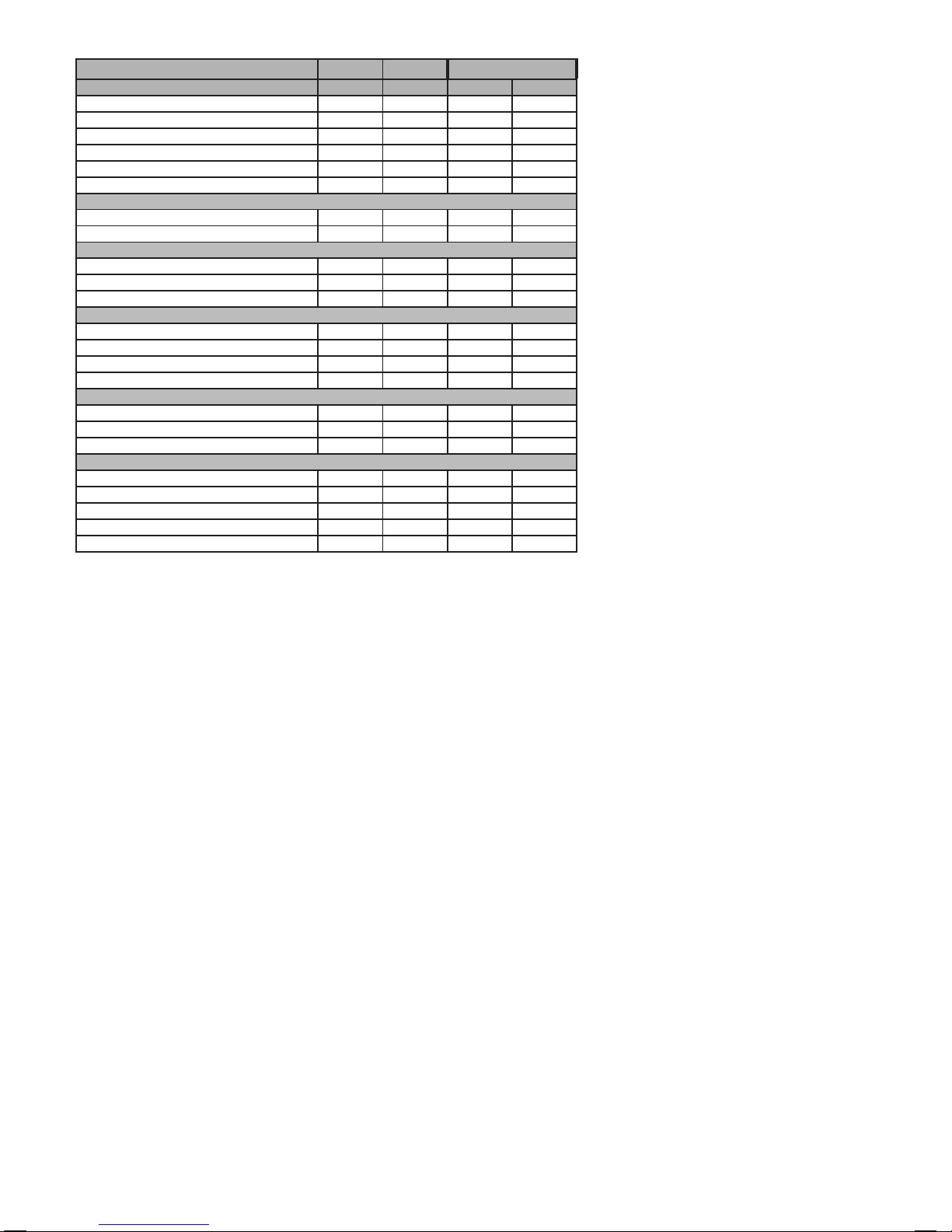
MODEL
SYMBOL UNITS 30 35
Condensing Boiler n/a n/a yes yes
Low Temperature Boiler n/a n/a no no
B1 Boiler n/a n/a no no
Cogeneration Space Heater n/a n/a no no
Equipped with a Supplementary Heater n/a n/a no no
Combination Heater n/a n/a yes yes
Nominal Heat Output for Space Heating
Full Load P
4 kW 24.3 24.3
Part Load P
1 kW 8.0 8.0
Auxiliary Electricity Consumption
Full Load el
max kW 0.032 0.029
Part Load el
min kW 0.013 0.013
Standby P
SB kW 0.005 0.005
Seasonal Space Heating Energy Efciency
Full Load
ƞ
4
% 90.0 90.0
Part Load
ƞ
1
% 98.7 98.7
Standby Loss P
stby kW 0.050 0.050
Ignition P
ign kW 0 0
Emissions NO
x mg/kWh 28 33
Annual Energy Consumption Q
HE GJ 75 75
Sound Power Level, Indoors L
WA dB 46 44
Domestic Hot Water
Q
elec kWh 0.075 0.074
ƞ
WH
% 78 78
Q
fuel kWh 7.700 7.700
AEC kWh 16 16
AFC GJ 6 6
ERP DATA

3
Installation and Servicing
ULTRA+ COMBI BOILER
ZANUSSI
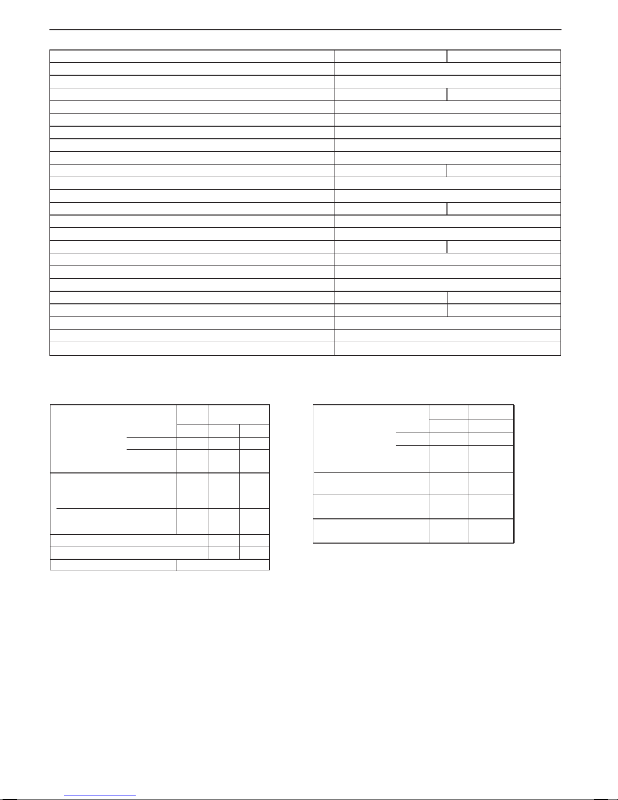
ERP DATA
SYMBOL UNITS MODEL
30 35
Condensing boiler YES
Seasonal Space heating efciency class A
Rated heat output kW 24
Seasonal space heating energy efciency
ƞs
% 94*
Annual energy consumption Q
HE GJ 75
Sound power level, indoors L
WA dB 46 44
Water heating energy efciency class A
Seasonal Space Heating Energy Efciency of the Boiler *%
Temperature control (from che of temperature control) %
Class I Class II Class III Class IV Class V Class VI Class VII Class VIII
1% 2% 1.5% 2% 3% 4% 3.5% 5%
PRODUCT FICHE
The energy efciency of the package of products provided for in this document may not correspond to its actual energy efciency once installed in a
building, as the efciency is inuenced by further factors such as heat loss in the products in relation to the building size and its characteristics
Collector Size
(in m2)
Tank Volume
(in m3)
Collector
Efciency
(in %)
Tank rating
A* = 0.95
A = 0.91
B = 0.86
C = 0.83
D-G = 0.81
Solar Contribution (from che of solar device)
Seasonal Space Heating Energy Efciency of Package
TOTAL: A+B+C=
Seasonal Space Heating Energy Efciency Class of Package
= (‘III ’x + ‘IV ’ x ) x 0.9 x ( / 100 x =
%
%
GG F E D C B A A+ A++
A+++
< 30% ≥ 30% ≥ 34% ≥ 36% ≥ 75% ≥ 82% ≥ 90% ≥ 98% ≥ 125% ≥ 150%
A
B
C

4
Installation and Servicing

5
Installation and Servicing
DOCUMENT AMENDMENTS
Relevant Installation changes implemented in this book from Mod Level ......................... A02 (Oct 16) to A03 (Mar 17)
The Manufacturer reserve the right to vary specication without notice
FOR ANY TECHNICAL QUERIES PLEASE RING THE
INSTALLER SUPPORT HELPLINE : 01482 498663
NOTE. BOILER RESTART PROCEDURE -
To restart the boiler press the RESTART button. The boiler will repeat the ignition sequence if a heat
demand is present.
NOTES FOR THE INSTALLER
Page 2 - ERP Data Table
Update to Table
Page 3 - Product FICHE
Update to ERP Data
Section 2.9 - Determining the Flue Length and Flue Packs Required
Update to Powered Vertical Flue table
Section 2.15 - Assembling the Roof Flue Kit
Image updated showing new min & max angles
Section 3.1 - Servicing Schedule
Servicing Producedure updated
Section 4.1 - Fault Finding Chart
Fault Code “FA” added.
USER GUIDE
Section 8 - Fault Codes
Fault Code “FA” added.

6
Installation and Servicing

7
Installation and Servicing
1 GENERAL .................................................................... 8
1.1 Introduction ................................................................ 10
1.2 Operation ................................................................... 10
1.3 Safe Handling ............................................................. 10
1.4 Optional Extra Kits ..................................................... 11
1.5 Safety ......................................................................... 11
1.6 Safe Handling Of Substances .................................... 11
1.7 Location of Boiler ...................................................... 12
1.8 Gas Supply ................................................................. 12
1.9 Flue Installation .......................................................... 12
1.10 Terminal ...................................................................... 13
1.11 Air Supply ................................................................... 13
1.12 Water Circulation System ........................................... 13
1.13 Boiler Control Interlocks ............................................. 13
1.14 Electrical Supply ......................................................... 13
1.15 Condensate Drain ...................................................... 13
1.16 Boiler Dimensions, Services & Clearances ................ 14
1.17 System Requirements ................................................ 15
1.18 Water Treatment.........................................................16
1.19 System Balancing ...................................................... 16
2 INSTALLATION ......................................................... 17
2.1 Boiler Assembly - Exploded View ............................... 17
2.2 Unpacking .................................................................. 18
2.3 Unpacking Cont’d ....................................................... 19
2.4 Front Panel Removal ................................................. 19
2.5 Wall Mounting Template ............................................. 20
2.6 Preparing The Wall ..................................................... 20
2.7
Fitting The Wall Mounting Plate .................................... 20
2.8 Mounting The Boiler ................................................... 20
2.9 Determining The Flue Length & Flue Packs Req’d ... 21
2.10 Cutting & Setting The Flue Length ............................. 23
2.11 Installing The Flue ...................................................... 24
2.12 Fitting The Optional Roof Flue Kit .............................. 25
2.13 Roof Flue Kit Contents / Options ................................ 25
2.14 Flue Terminal Position ................................................ 26
2.15 Assembling The Roof Flue Kit .................................... 27
2.16 Condensate Drain ...................................................... 28
2.17 Connections & Filling ................................................. 30
2.18 Electrical Connections ................................................ 32
2.19 Installer Wiring ........................................................... 32
2.20 External Wiring ........................................................... 33
2.21 Replacing Pre-Fitted Mains Cable ............................. 33
2.22 Wiring Diagram .......................................................... 34
2.23 Commissioning And Testing ....................................... 35
2.24 Initial Lighting ............................................................. 36
2.25 General Checks ......................................................... 37
2.26 Restart Procedure ...................................................... 38
2.27 Accessing The Installer Mode .................................... 38
2.28 Handing Over ............................................................. 38
3 SERVICING ............................................................... 39
3.1 Servicing Schedule .................................................... 39
3.2 Boiler Front Panel Removal / Replacement ............... 40
3.3 Fan And Venturi Assembly Removal And Cleaning .... 40
3.4 Burner Removal & Cleaning ....................................... 41
3.5 Cleaning the Condensate Trap/Siphon ...................... 41
3.6 Cleaning the Heat Exchanger .................................... 42
3.7 Reassembly ............................................................... 42
3.8 Replacement Of Components .................................... 43
3.9 Fan Replacement ....................................................... 43
3.10 Burner Injector Replacement ..................................... 44
3.11 Burner Replacement .................................................. 44
3.12 Return Thermistor Renewal ....................................... 45
3.13 Ignition Electrode Replacement ................................. 45
3.14 Flame Detection Electrode Replacement ................... 46
3.15 Spark Generator Replacement .................................. 46
3.16 Gas Control Valve Replacement ................................ 46
3.17 Diverter Valve Actuator Replacement ........................ 47
3.18 Condensate Trap/Siphon Replacement ..................... 47
3.19 PCB Replacement ...................................................... 48
3.20 DHW Flow Turbine Sensor Replacement ..................48
3.21 Draining The Boiler .................................................... 49
3.22 Pressure Gauge Renewal .......................................... 49
3.23 Safety Relief Valve Renewal ...................................... 50
3.24 Pump Automatic Air Vent Replacement ..................... 50
3.25 DHW Filter & Flow Reg Cleaning/Replacement ......... 50
3.26 Diverter Valve Body Assembly Replacement ............. 51
3.27 DHW Plate Heat Exch. Replacement ......................... 51
3.28 Pump Head Replacement .......................................... 51
3.29 CH Water Pressure Switch Replacement .................. 52
3.30 Flow Thermistor Replacement ................................... 52
3.31 Heat Engine Renewal ................................................ 53
3.32 Expansion Vessel Recharging & Replacement .......... 54
4 FAULT FINDING ........................................................ 55
4.1 Fault Finding Chart Main Menu .................................. 55
4.2 ‘L1’ - Flow Temp Overheat Lockout ............................ 56
4.3 ‘L2’ - Ignition Lockout .................................................56
4.4 ‘L6’ - False Flame Lockout ........................................ 57
4.5 ‘F1’ - Low Water Pressure .......................................... 57
4.6 ‘F2 Or Fn Or Ln’ - Flame Loss....................................57
4.7 ‘F3’ - Fan Fault ........................................................... 58
4.8 ‘F4 Or L4’ - Flow Thermistor Fault ..............................58
4.9 ‘F5 Or L5’ - Return Thermistor Fault ..........................58
4.10 ‘F6’ - Outside Sensor Fault.........................................59
4.11 No CH Operation but HW Works OK ......................... 59
4.12 No HW But CH On ..................................................... 60
4.13 No Display .................................................................. 60
5 SPARE PARTS .......................................................... 61
6 BENCHMARK & COMMISSIONING ......................... 62
CONTENTS
8
Installation and Servicing
SECTION 1 - GENERAL
30 35
Gas supply 2H - G20 - 20mbar
Gas Supply Connection 15mm copper compression
Injector Size mm 4.65 4.9
Inlet Connection Domestic Hot Water 15mm copper compression
Outlet Connection Domestic Hot Water 15mm copper compression
Flow Connection Central Heating 22mm copper compression
Return Connection Central Heating 22mm copper compression
Flue Terminal Diameter mm 100
Average Flue Temp-Mass Flow Rate (DHW) 68ºC - 13g/s 73ºC - 15g/s
Maximum Working Pressure (Sealed Systems) bar 2.5
Maximum Domestic Hot Water Inlet Pressure bar 10.0
Minimum Domestic Hot Water Inlet Pressure* bar 1.3 1.3**
Minimum DHW Inlet Pressure to operate at 0.6bar system pressure All Model sizes 0.5 bar
Electrical Supply 230 V ~ 50 Hz
Power Consumption W 101 114
Fuse Rating External : 3A Internal : T4A HRC L250 V
Water content Central Heating litre 1.2
Domestic Hot Water litre 0.5
Packaged Weight kg 33.8 33.9
Maximum Installation Weight kg 29 29.1
Boiler Casing Size Height mm 700
Width mm 395
Depth mm 278
Table 1 - General Data
Note. Gas consumption is calculated using a
caloric value of 38.7 MJ/m
3
gross or 34.9 MJ/m3
nett
To obtain the gas consumption at a different caloric
value:
a. For l/s - divide the gross heat input (kW) by the
gross C.V. of the gas (MJ/m
3
)
b. For Btu/h - multiply the gross heat input (kW) by
26.8
c. For ft
3
/h - divide the gross heat input (Btu/h) by
the gross C.V. of the gas (Btu/ft3)
d. For m
3
/h - multiply l/s by 3.6
Key to symbols
GB = United Kingdom IE = Ireland (Countries of destination)
PMS = Maximum operating pressure of water
C13 C33 C53
= A room sealed appliance designed for connection via ducts to a
horizontal or vertical terminal, which admits fresh air to the burner
and discharges the products of combustion to the outside through
orices which, in this case, are concentric. The fan is up stream of
the combustion chamber.
I
2H
= An appliance designed for use on 2nd Family gas, Group H only.
* The value is used in the UK Government’s Standard Assessment Procedure (SAP) for energy rating of dwellings. The test data from
which it has been calculated have been certied by a notied body.
*Required for maximum ow rate. Boiler operates down to 2 l/min DHW delivery
** In areas of low water pressure the DHW restrictor can be removed
Maximum DHW Input : 30 35
Nett CV kW 30.4 35.4
Gross CV kW 33.7 39.3
Gas Consumption m
3
/h 3.135 3.657
Maximum kW 30.3 35.3
DHW Output
DHW Flow Rate l/min 12.4 14.5
at 35°C temp. rise.
DHW Specic Rate l/min 14.5 16.9
Boiler Input : Max. Min.
30 35
Boiler Input ‘Q’ Nett CV kW 24.3 6.1 7.1
Gross CV kW 27.0 6.7 7.9
Gas Consumption m
3
/h 2.512 0.627 0.734
Boiler Output :
Non Condensing kW 24.2 6.1 7.1
70
o
C Mean Water temp.
Condensing kW 25.6 6.4 7.5
40
o
C Mean Water temp.
Seasonal efciency* SEDBUK 2005 91.1% 91.1%
Seasonal efciency* SEDBUK 2009 89.6% 89.6%
NOx Classication CLASS 5
Table 2 - Performance Data - Central Heating
Table 3 - Performance Data - Domestic Hot Water
9
Installation and Servicing
SECTION 1 - GENERAL
Boiler Page
Make and model .........................................................9
Appliance serial no. on data badge .......... Front Cover
SEDBUK No. % ..........................................................8
Controls
Time and temperature control to heating ................. 32
Time and temperature control to hot water ............. 32
Heating zone valves ................................................n/a
TRV’s........................................................................ 13
Auto bypass .............................................................13
Boiler interlock ..........................................................13
For .................................................................... all boilers
Flushing to BS.7593 .................................................16
Inhibitor .................................................................... 16
Central heating mode
Heat input ...................................................to be calculated
For assistance see Technical Helpline on the back page
Page
Burner operating pressure ...................................... n/a
Central heating ow temp. ...........measure and record
Central heating return temp. ........measure and record
For combination boilers only
Scale reducer ........................................................... 16
Hot water mode
Heat input ............................................ to be calculated
Max. operating burner pressure .............................. n/a
Max. operating water pressure ........ measure & record
Cold water inlet temp ...................... measure & record
Hot water outlet temp. ..................... measure & record
Water ow rate at max. setting ........ measure & record
For condensing boilers only
Condensate drain ................................................ 28-29
For all boilers: complete, sign & hand over to customer
For GB, to comply with Building Regulations Part L1 (Part 6 in Scotland) the boiler should be tted in accordance with the
manufacturer’s instructions. Self-certication that the boiler has been installed to comply with Building Regulations can be
demonstrated by completing and signing the Benchmark Commissioning Checklist.
Before installing this boiler, read the Code of Practice sheet at the rear of this book.
BENCHMARK COMMISSIONING CHECKLIST DETAILS
NOTE TO THE INSTALLER:
COMPLETE
THE BENCHMARK COMMISSIONING
CHECKLIST AND LEAVE THESE
INSTRUCTIONS WITH APPLIANCE
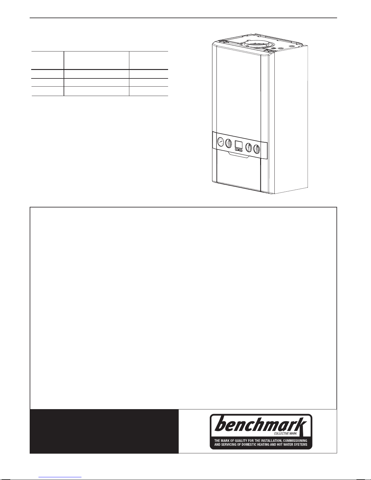
Boiler size G.C. Appliance No. PI No.
(Benchmark No.)
30 47-002-03 86CR16
35 47-002-04 86CR16
Natural Gas only
Destination Country: GB, IE
ZANUSSI ULTRA+ COMBI

10
Installation and Servicing
SECTION 1 - GENERAL
1.1 INTRODUCTION
The Zanussi Ultra+ Combi range of boilers are wall mounted, full
sequence, automatic spark ignition, low water content, fanned
ue, high efciency, condensing, combination gas boilers.
Note. Due to the high efciency of the boiler a plume of water
vapour will form at the terminal during operation.
Central heating (CH) output is fully modulating with a range of:
30 6.1 to 24.2kW
35 7.1 to 24.2kW
Instantaneous domestic hot water (DHW) output is also fully
modulating with a maximum of :
30 30.3kW
35 35.3kW
The boiler is supplied fully assembled with DHW plate heat
exchanger, diverter valve, circulating pump, pressure gauge,
safety valve and CH expansion vessel.
Variable CH and DHW temperature controls are tted on the user
control and the boiler features a DHW preheat facility.
The boiler includes as standard:
- Automatic bypass
- Boiler frost protection
- Daily pump and diverter valve exercise.
The boiler casing is of white painted mild steel with a white
polymer front panel.
The boiler temperature controls are visibly located in the control
panel on the front of the boiler.
The heat exchanger is manufactured from cast aluminium.
The boiler is suitable for connection to fully pumped, sealed
heating systems ONLY. Adequate arrangements for completely
draining the system by provision of drain cocks MUST be provided
in the installation pipework.
Pipework from the boiler is routed downwards.
Data Plate
The boiler model and serial number can be located on the
bottom of the boiler casing, shown in Section 1.16 - Water & Gas
Connection Diagram.
1.2 OPERATION
With no demand for CH, the boiler res only when DHW is drawn
off, or periodically for a few seconds without any DHW draw-off,
in order to maintain the DHW plate heat exchanger in a heated
condition. This only occurs if the “PREHEAT” button is pressed
and the display reads “HOT WATER PREHEAT ON”.
When there is a demand for CH, the heating system is supplied
at the selected temperature of between 30
o
C and 80oC, until
DHW is drawn off. The full output from the boiler is then directed
via the diverter valve to the plate heat exchanger to supply a
nominal DHW draw-off of
30 12.4 l/min at 35ºC temperature rise.
35 14.5 l/min at 35ºC temperature rise.
The DHW draw off rate specied above is the nominal that the
boiler ow regulator will give. Due to system variations and
seasonal temperature uctuations DHW ow rates/temperature
rise will vary, requiring adjustment at the draw off tap.
At low DHW draw-off rates the maximum temperature may
exceed 65ºC.
The boiler features a comprehensive diagnostic system which
gives detailed information on the boiler status when operating,
and performance of key components to aid commissioning and
fault nding.
1.3 SAFE HANDLING
This boiler may require 2 or more operatives to move it to its
installation site, remove it from its packaging base and during
movement into its installation location. Manoeuvring the boiler
may include the use of a sack truck and involve lifting, pushing
and pulling.
Caution should be exercised during these operations.
Operatives should be knowledgeable in handling techniques
when performing these tasks and the following precautions
should be considered:
• Grip the boiler at the base.
• Be physically capable.
• Use personal protective equipment as appropriate, e.g.
gloves, safety footwear.
During all manoeuvres and handling actions, every attempt
should be made to ensure the following unless unavoidable and/
or the weight is light.
• Keep back straight.
• Avoid twisting at the waist.
• Avoid upper body/top heavy bending.
• Always grip with the palm of the hand.
• Use designated hand holds.
• Keep load as close to the body as possible.
• Always use assistance if required.

11
Installation and Servicing
SECTION 1 - GENERAL
1.4 OPTIONAL EXTRA KITS
• Horizontal Flue Terminal 600mm long
• Horizontal Telescopic Flue 600mm long
• Horizontal Telescopic Flue 1000mm long
• Flue Extension Ducts (1000mm long)
• Flue Extension Ducts (2000mm long)
• Flue Extension Ducts (500mm long)
30-up to 8m
35-up to 6m
• 90
o
Elbow Kit (maximum per installation).
30-upto 6 elbows
35-upto 4 elbows
• 45
o
Elbow Kit (maximum per installation).
30-upto 6 elbows
35-upto 4 elbows
• Concentric Flue Screw Retaining Kit
• Roof Flue Kit inc. vertical connection (to a max. of 7.5m)
• Powered Vertical Flue Kit (5m primary and 17m secondary
is a typical maximum length. For alternative details refer to
Powered Vertical Instructions)
• Weather Collar (Universal)
• Weather Collar (Flat Roof)
• High Level Flue Outlet Kit
• Flue Deector Kit
• Balcony Flue Kit
• Soft Flue Kit
• Raised Horizontal Flue Outlet Kit
• Adjustable Flue Support Bracket
• Mechanical Timer (24 hr) 5V Kit
• Stand-Off Kit
• DHW Expansion Vessel Kit
• Condensate Pump Kit
• Security Bracket Kit
• Safety Valve Drain Outlet Pipe Kit
• OpenTherm Harness Kit
1.5 SAFETY
Current Gas Safety (installation and use) regulations or rules
in force:
The appliance is suitable only for installation in GB and IE and
should be installed in accordance with the rules in force.
In GB, the installation must be carried out by a Gas Safe
Registered Engineer. It must be carried out in accordance with
the relevant requirements of the:
• Gas Safety (Installation and Use) Regulations
• Appropriate Building Regulations, either The Building
Regulations, The Building Regulations (Scotland), Building
Regulations (Northern Ireland).
• Water Fittings Regulations or Water byelaws in Scotland.
• Current I.E.E. Wiring Regulations.
Where no specic instructions are given, reference should be
made to the relevant British Standard Code of Practice.
In IE, the installation must be carried out by a Registered Gas
Installer (RGII) and installed in accordance with the current edition
of I.S.813 “Domestic Gas Installations”, the current Building
Regulations and reference should be made to the current ETCI
rules for electrical installation.
Detailed recommendations are contained in the following British
Standard Codes of Practice:
BS.5440:1 Flues (for gas appliances of rated input not
exceeding 70 kW).
BS.5440:2 Ventilation (for gas appliances of rated input not
exceeding 70 kW).
BSEN. 12828 Heating Systems in buildings: Design for water
based heating systems.
BSEN 12831 Heating Systems in buildings: Method for
calculation of the design heat load.
BSEN 14336 Heating Systems in buildings: Installation and
commissioning of water based heating
systems.
BS.5546 Installation of gas hot water supplies for domestic
purposes (2nd Family Gases)
BS.6798 Installation of gas red hot water boilers of rated
input not exceeding 70 kW.
BS.6891 Low pressure installation pipes.
Health & Safety Document No. 635.
The Electricity at Work Regulations, 1989.
The manufacturer’s notes must NOT be taken, in any way, as
overriding statutory obligations.
IMPORTANT. These appliances are CE certicated for safety
and performance. It is, therefore, important that no external
control devices, e.g. ue dampers, economisers etc., are
directly connected to these appliances unless covered by
these Installation and Servicing Instructions or as otherwise
recommended by the manufacturer in writing. If in doubt please
enquire.
Any direct connection of a control device not approved by the
manufacturer could invalidate the certication and the normal
appliance warranty. It could also infringe the Gas Safety
Regulations and the above regulations.
1.6 SAFE HANDLING OF SUBSTANCES
No asbestos, mercury or CFCs are included in any part of the
boiler or its manufacture.
12
Installation and Servicing
SECTION 1 - GENERAL
1.8 GAS SUPPLY
The local gas supplier should be consulted, at the installation
planning stage, in order to establish the availability of an adequate
supply of gas. An existing service pipe must NOT be used without
prior consultation with the local gas supplier.
The boiler MUST be installed on a gas supply with a governed
meter only.
A gas meter can only be connected by the local gas supplier or
by a Gas Safe Registered Engineer. In IE by a Registered Gas
Installer (RGII).
An existing meter should be checked, preferably by the gas
supplier, to ensure that the meter is adequate to deal with the rate
of gas supply required.
It is the responsibility of the Gas Installer to size the gas
installation pipework in accordance with BS.6891. Whilst the
principle of the 1:1 gas valve ensures the Zanussi range is
able to deliver its full output at inlet pressures as low as 14mb,
other gas appliances in the property may not be as tolerant.
When operating pressures are found to be below the minimum
meter outlet of 19mb these should be checked to ensure this is
adequate for correct and safe operation.
Allowing for the acceptable pressure loss of 1mb across the
installation pipework, it can be assumed that a minimum permitted
operating pressure of 18mb will be delivered to the inlet of
the appliance. (Reference BS.6400-1 Clause 6.2 Pressure
Absorption).
The external gas cock could further reduce the operating pressure
when measured at its test point. The pressure drop is relative to
the heat input to the boiler (kW), refer to graph below.
0
0.5
1
1.5
2
2.5
3
0 10 20 30 40 50
Pressure drop (mbar )
Heat Input to Boiler (kW)
Gas Cock Pressure Drop
IMPORTANT.
Installation pipes must be tted in accordance with BS.6891. In IE
refer to IS.813:2002.
The complete installation MUST be tested for gas tightness and
purged as described in the above code.
1.9 FLUE INSTALLATION
Pluming will occur at the terminal so terminal positions where this
could cause a nuisance should be avoided.
The ue must be installed in accordance with the
recommendations of BS.5440-1.
In IE refer to I.S. 813.
The following notes are intended for general guidance:
1. The boiler MUST be installed so that the terminal is exposed
to external air.
1.7 LOCATION OF BOILER
The boiler must be installed on a at and vertical internal wall,
capable of adequately supporting the weight of the boiler and any
ancillary equipment.
The boiler may be tted on a combustible wall and insulation
between the wall and the boiler is not necessary, unless required
by the local authority.
For electrical safety reasons there must be no access available
from the back of the boiler.
The boiler must not be tted outside.
Timber Framed Buildings
If the boiler is to be tted in a timber framed building it should be
tted in accordance with the Institute of Gas Engineering document
IGE/UP/7:2006 Edition 2.
Bathroom Installations
This appliance is rated IP20.
The boiler may be installed in any room or internal space, although
particular attention is drawn to the requirements of the current
IEE (BS.7671) Wiring Regulations and the electrical provisions of
the building regulations applicable in Scotland, with respect to the
installation of the boiler in a room or internal space containing a bath
or shower. For IE reference should be made to the current ETCI
rules for electrical installations and I.S. 813:2002.
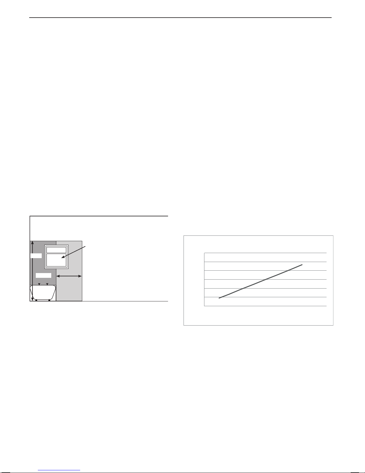
If the appliance is to be installed in a room containing a bath or
shower then, providing water jets are not going to be used for
cleaning purposes (as in communal baths/showers), the appliance
must be installed beyond Zone 2, as detailed in BS.7671.
0.6m
Zone 0
Recessed
window
Zone 2
Ceiling
3G8913a
2.25m
Zone 1
Compartment Installations
A compartment used to enclose the boiler should be designed and
constructed specially for this purpose.
An existing cupboard or compartment may be used, provided that it
is modied for the purpose.
In both cases, details of essential features of cupboard /
compartment design, including airing cupboard installation, are to
conform to the following:
• BS.6798 (No cupboard ventilation is required - see ‘Air Supply’
for details).
• The position selected for installation MUST allow adequate
space for servicing in front of the boiler, This can be by means
of an opening door
• For the minimum clearances required for safety and subsequent
service, see the wall mounting template and Section 1.16. In
addition, sufcient space may be required to allow lifting access
to the wall mounting plate.
13
Installation and Servicing
SECTION 1 - GENERAL
2. It is important that the position of the terminal allows the free
passage of air across it at all times.
3. Minimum acceptable spacing from the terminal to obstructions
and ventilation openings are specied in
Table 4.
4. Where the lowest part of the terminal is tted less than 2m
above a balcony, above ground or above a at roof to which
people have access then the terminal MUST be protected by a
purpose designed guard.
Terminal guards are available from boiler suppliers. (Ask for
TFC ue guard model no. K6 - round, plastic coated). In case
of difculty contact:
TFC Group. Tel. + 44 (0) 01732 351 680
Tower House, Vale Rise Fax. + 44 (0) 01732 354 445
Tonbridge. Kent TN9 1TB www.tfc-group.co.uk
Ensure that the guard is tted centrally.
5. The ue assembly shall be so placed or shielded as to prevent
ignition or damage to any part of any building.
6. The air inlet/products outlet duct and the terminal of the boiler
MUST NOT be closer than 25mm to combustible material.
Detailed recommendations on the protection of combustible
material are given in BS.5440-1.
IMPORTANT. It is essential to ensure, in practice, that products
of combustion discharging from the terminal cannot re-enter the
building or buildings through any openings into the building such
as ventilators, windows, doors, or other sources of natural air
inltration, such as forced ventilation openings etc.
If products of combustion re-entry is identied or suspected this
should be immediately investigated and corrected following the
guidance provided in the current Gas Industry Unsafe Situation
Procedure.
1.10 TERMINAL
The terminal assembly can be adapted to accommodate various
wall thicknesses. Refer to Section 2.9.
1.11 AIR SUPPLY
It is NOT necessary to have a purpose-provided air vent in the
room or internal space in which the boiler is installed. Neither
is it necessary to ventilate a cupboard or compartment in which
the boiler is installed, due to the low surface temperatures of
the boiler casing during operation; therefore the requirements of
BS.6798, Clause 12, and BS. 5440:2 may be disregarded.
1.12 WATER CIRCULATION SYSTEM
IMPORTANT.
A minimum length of 1 metre of copper pipe MUST be tted
to both ow and return connections from the boiler before
connection to any plastic piping.
The central heating system should be in accordance with BS.6798
and, in addition, for smallbore and microbore systems, BS.5449.
WATER TREATMENT - Refer to Section 1.19.
1.13 BOILER CONTROL INTERLOCKS
Central heating system controls should be installed to ensure that
the boiler has no demand when there is no requirement from the
system, in compliance with Building Regulations.
Heating systems utilising full thermostatic radiator valve control
of temperature in individual rooms should also be tted with a
room thermostat controlling the temperature in a space served by
radiators not tted with such a valve.
When thermostatic radiator valves are used, the space heating
temperature control over a living / dining area or hallway having
a heating requirement of at least 10% of the minimum boiler heat
output should be achieved using a room thermostat, whilst other
rooms are individually controlled by thermostatic radiator valves.
However, if the system employs thermostatic radiator valves on all
radiators, or two port valves, then a bypass circuit must be tted
with an automatic bypass valve to ensure a ow of water should
all valves be in the closed position.
1.14 ELECTRICAL SUPPLY
WARNING.
This appliance must be earthed.
Wiring external to the appliance MUST be in accordance with
the current I.E.E. (BS.7671) Wiring Regulations and any local
regulations which apply. For IE reference should be made to the
current ETCI rules for electrical installations.
The mains supply to the boiler and system wiring centre shall
be through one common fused double pole isolator and for new
heating systems, and where practical replacement installations,
the isolator shall be situated adjacent to the appliance.
1.15 CONDENSATE DRAIN (Refer to Section 2.16)
A condensate drain is provided on the boiler. This drain must be
connected to a drainage point on site. All pipework and ttings in
the condensate drainage system MUST be made of plastic - no
other materials may be used.
IMPORTANT.
Any external runs must be in accordance with BS.6798.
The drain outlet on the boiler is sized for standard 21.5mm
overow pipe. It is a universal tting to allow use of different
brands of pipework.
* Only one reduction down to 25mm is allowable per installation
otherwise BS5440-1 dimensions must be followed.
Flue Terminal Positions
Min. Spacing*
1. Directly below, above or alongside an open
window, air vent or other ventilation opening. 300mm
2. Below guttering, drain pipes or soil pipes. 25mm*
BS5440-1 75mm
3. Below eaves. 25mm*
BS5440-1 200mm
4. Below balconies or a car port roof. 25mm*
BS5440-1 200mm
5. From vertical drain pipes or soil pipes. 25mm*
BS5440-1 150mm
6. From an internal or external corner or to a 25mm*
boundary alongside the terminal. BS5440-1 300mm
7. Above adjacent ground, roof or balcony level. 300mm
8. From a surface or a boundary facing the terminal. 600mm
9. From a terminal facing a terminal. 1,200mm
10. From an opening in a car port
(e.g. door or window) into dwelling. 1,200mm
11. Vertically from a terminal on the same wall. 1,500mm
12. Horizontally from a terminal on the wall. 300mm
Vertical Terminals
13. Above the roof pitch with roof slope of all angles. 300mm
Above at roof. 300mm
14. From a single wall face. 300mm
From corner walls. 300mm
15. Below velux window 2000mm
16. Above or side of velux window 600mm
Table 4 - Balanced Flue Terminal Position
14
Installation and Servicing
SECTION 1 - GENERAL
Underside View - Dimensions to Wall
W A L L
W A L L
CH FLOW
DATA PLATE
DHW OUTLET
COND. DRAIN
GAS INLET
Centre line
of boiler
DHW INLET
CH RETURN
PRV
43.5 65
28.5 28.5
60.6 75 37.556.4
3952.5
2.5
from case
700
Side flue
dim. A
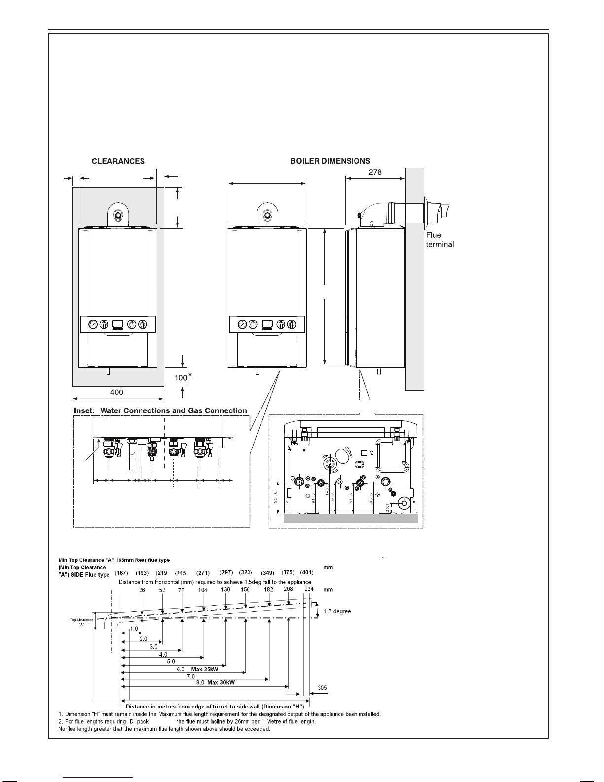
1.16 BOILER DIMENSIONS, SERVICES & CLEARANCES
The boiler connections are made on the boiler connection tails.
Refer to Section 2.17.
The following minimum clearances must be maintained for
operation and servicing.
Additional space will be required for installation, depending upon
site conditions.
Side and Rear Flue
a.
Provided that the ue hole is cut accurately, e.g. with a core
drill, the ue can be installed from inside the building where
wall thicknesses do not exceed 600mm. Where the space into
which the boiler is going to be installed is less than the length
of ue required the ue must be tted from the outside.
Installation from inside ONLY
b. If a core boring tool is to be used inside the building the
space in which the boiler is to be installed must be at least
wide enough to accommodate the tool.
Front clearance
The minimum front
clearance when built in to
a cupboard is 5mm from
the cupboard door but
450mm overall clearance
is still required, with the
cupboard door open, to
allow for servicing.
* Bottom clearance
Bottom clearance after
installation can be
reduced to 5mm. This
must be obtained with
an easily removable
panel to provide the
100mm clearance
required for servicing.
extensions
15
Installation and Servicing
SECTION 1 - GENERAL
General
1. The installation must comply with all relevant national and local
regulations.
2. The installation should be designed to work with flow
temperatures of up to 84
o
C.
3. All components of the system must be suitable for a working
pressure of 3 bar and a maximum design temperature of 110
o
C.
Extra care should be taken in making all connections so that the
risk of leakage is minimised.
The following components are incorporated within the appliance:
a. Circulating pump.
b. Safety valve, with a non-adjustable preset lift pressure of 3
bar.
c. Pressure gauge, covering a range of 0 to 4 bar.
d. An 8-litre expansion vessel, with an initial charge pressure
of 0.75 bar.
4. ‘Make-up’ Water. Provision must be made for replacing water
loss from the system, either :
a. From a manually lled ‘make-up’ vessel with a readily visible
water level. The vessel should be mounted at least 150mm
above the highest point of the system and be connected
through a non-return valve to the system, tted at least
150mm below the ‘make-up’ vessel on the return side of
the radiators. or
b. Where access to a ‘make-up’ vessel would be difcult, by
pre-pressurisation of the system.
The maximum cold water capacity of the system should
not exceed 143 litres, if not pressurized. However, if
the system is to be pressurized, the efciency of the
expansion vessel will be reduced and a larger vessel
(or smaller system volume) may be necessary. If the
capacity of the vessel is not considered sufcient for this,
or for any other reason, an additional vessel MUST be
installed on the return to the boiler.
Guidance on vessel sizing is given in table above.
Notes
a. The method of lling, relling, topping up or ushing sealed
primary hot water circuits from the mains via a temporary hose
connection is only allowed if acceptable to the local water
authority.
b. Antifreeze uid, corrosion and scale inhibitor uids suitable for
use with boilers having aluminium heat exchangers may be used
in the central heating system.
1.17 SYSTEM REQUIREMENTS - Central Heating
Water Flow Rate and Pressure Loss
Max CH output kW 24.2
Water ow rate l/min 17.3
Temperature differential
o
C 20
Head available for m.w.g. 3.4
system
Safety valve setting bar 3.0
Vessel charge pressure bar 0.5 to 0.75
System pre-charge pressure bar None 1.0
System volume Expansion vessel
(litres) volume (litres)
25 1.6 1.8
50 3.1 3.7
75 4.7 5.5
100 6.3 7.4
125 7.8 9.2
150 9.4 11.0
175 10.9 12.9
190 11.9 14.0
200 12.5 14.7
250 15.6 18.4
300 18.8 22.1
For other system volumes
multiply by the factor across 0.063 0.074
5. Filling
The system may be lled by the following method:
Where the mains pressure is excessive a pressure
reducing valve must be used to facilitate lling.
a. Thoroughly ush out the whole system with cold
water.
b. Fill and vent the system until the pressure gauge
registers 1bar and examine for leaks. Refer to
Section 2.17 for lling detail.
c. Check the operation of the safety valve by raising the
water pressure until the valve lifts. This should occur
within 0.3bar of the preset lift pressure.
d. Release water from the system until the
minimum system design pressure is reached;
1.0 bar if the system is to be pre-pressurised.
continued . . . . . .

16
Installation and Servicing
SECTION 1 - GENERAL
The boiler does not normally need a bypass but at
least some radiators on the heating circuit, of load
of at least 10% of the minimum boiler output, must
be provided with twin lockshield valves so that this
minimum heating load is always available. See note
regarding thermostatic radiator valves on page 13.
Note. Systems incorporating zone valves which could
completely cut off the ow through the system must
also include a bypass.
BALANCING
1. Set the programmer to ON.
Close the manual or thermostatic valves on all
radiators, leaving the twin lockshield valves (on the
radiators referred to above) in the OPEN position.
Turn up the room thermostat and adjust the
lockshield valve to give an uninterrupted ow
through the radiator.
These valves should now be left as set.
2. Open all manual or thermostatic radiator valves
and adjust the lockshield valves on the remaining
radiators, to give around 20
o
C temperature drop at
each radiator.
3. Adjust the room thermostat and programmer to
NORMAL settings.
1.18 SYSTEM BALANCING
1.19 WATER TREATMENT
CENTRAL HEATING
This boiler has an ALUMINIUM alloy heat exchanger.
IMPORTANT.
The application of any other treatment to this product
may render the boiler guarantee Invalid.
The manufacturer recommends Water Treatment in
accordance with the Benchmark Guidance Notes on Water
Treatment in Central Heating Systems.
If water treatment is used the manufacturer recommend
only the use of
SCALEMASTER GOLD 100, FERNOX, MBI,
ADEY MC1, SENTINEL X100 or CALMAG CM100 inhibitors and
associated water treatment products, which must be used
in accordance with the manufacturers’ instructions.
2. If the boiler is installed in an existing system any
unsuitable additives MUST be removed by thorough
cleansing. BS 7593:2006 details the steps necessary
to clean a domestic heating system.
3. In hard water areas, treatment to prevent lime scale
may be necessary - however the use of articially
softened water is NOT permitted.
4. Under no circumstances should the boiler be red
before the system has been thoroughly ushed.
For further information contact:
Fernox Cookson Electronics
Forsyth Road, Sheerwater, Woking, Surrey GU21 5RZ
+44 (0) 8706 015000
Sentinel Performance Solutions
The Heath Business & Technical Park
Runcorn, Cheshire WA7 4QX
Tel: 0800 389 4670
Scalemaster Water Treatment Products
Emerald Way, Stone, Staffordshire ST15 0SR
Tel: +44 (0) 1785 811636
Calmag Ltd.
Unit 3-6, Crown Works, Bradford Road,
Sandbeds, Keighley, West Yorkshire BD20 5LN
Tel: +44 (0) 1535 210320
Adey Professional Heating Solutions
Gloucester Road, Cheltenham GL51 8NR
Tel: +44 (0) 1242 546700
........ SYSTEM REQUIREMENTS - CONT
Domestic Hot Water
1.
The DHW service must be in accordance with BS.5546 & BS.6700.
2.
Refer to Table 1 for minimum and maximum working pressures. In
areas of low mains water pressures the domestic hot water regulator
may be removed from the DHW ow turbine cartridge. Refer to
Section 3.20. The boiler will require the ow rate to be set to obtain
a temperature rise of 35oC at the tap furthest from the boiler.
3. The boilers are suitable for connection to most types of washing
machine and dishwasher appliances.
4. When connecting to suitable showers, ensure that:
a. The cold inlet to the boiler is tted with an approved anti-
vacuum or syphon non-return valve.
b. Hot and cold water supplies to the shower are of equal pressure.
5. Hard Water Areas
Where the water hardness exceeds 200mg/litre (200 ppm), it is
recommended that a proprietary scale reducing device is tted into the
boiler cold supply within the requirements of the local water company.
IMPORTANT. Provision must be made to accommodate the expansion
of DHW contained within the appliance. If the DHW inlet contains a
back ow prevention device or non-return valve, e.g. a water meter,
then a mini expansion vessel should be tted between the device and
the boiler in the cold inlet pipe.
Cold water, rising main and pipework in exposed areas need to
be suitably lagged to prevent freezing.
Note. A DHW Expansion Vessel kit is available as an option.
DOMESTIC HOT WATER
In hard water areas where mains water can exceed
200ppm Total Hardness (as dened by BS 7593:2006
Table 2) a scale reducing device should be tted into
the boiler cold supply within the requirements of the
local water company. The use of articially softened
water, however, is not permitted.
The manufacturer recommends the use of Fernox
Quantomat, Sentinel Combiguard,Calmag CalPhos
I scale reducing devices or Scalemaster In-line
Scale Inhibitor branded Ideal, which must be used in
accordance with the manufacturers’ instructions.
Notes.
1. It is most important that the correct concentration
of the water treatment products is maintained in
accordance with the manufacturers’ instructions.
17
Installation and Servicing
SECTION 2 - INSTALLATION
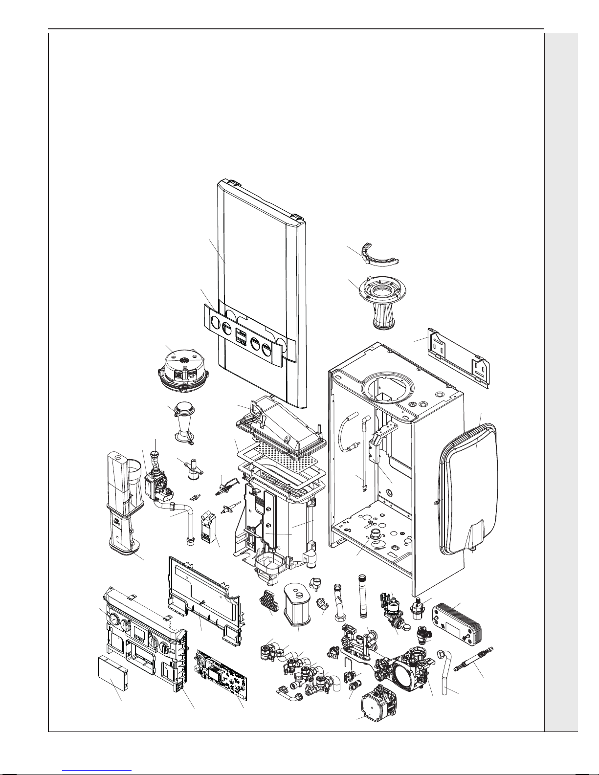
2.1 BOILER ASSEMBLY - Exploded View
Note that item numbers are linked to the spares list
104 CH Return Valve
105 CH Flow Valve
106 DHW Inlet & Outlet
107 Filling Loop Pipe
108 Pump Head
110 Auto Air Vent
111 Diverter Valve Motor
112
Diverter Valve Body & Paddle
113 Pressure Relief Valve
114 Pipe - PRV Outlet
115 Pipe - Flow
116 Pipe - Return
117 Pipe - Expansion Vessel
118 Expansion Vessel
119 Return Group Manifold
120 Flow Group Manifold
121 Plate Heat Exchanger
124 Flow Regulator
127 Flow Sensor/Turbine
131 Water Pressure Switch
135 Pressure Gauge
203 Gas Cock
204 Pipe - Gas Inlet
205 Gas Valve
206 Pipe - Gas Injector
211 Injector Assy
214 Venturi
215 Fan
217 Burner
218 Gasket - Burner
219 Sump Clean Out Cover
223 Flue Manifold
224 Flue Manifold Top
227 Clamp Retaining Flue Turret
228 Hose Condensate Internal
229 Siphon Trap
231
Condensate Outlet Connection
302 Primary PCB
304
Control Thermistor (Return)
306 Electrode Ignition
307 Electrode Detection
308 Ignitor Unit
309 Thermistor Flow
313 Ignition Lead
320 Detection Lead
324 Control Box Lid
325 Control Box Front
326 Blank Insert
401 Heat Engine
503 Wall Mounting Bracket
504 Front Panel
505 Fascia
506 Bracket - Gas Valve
507 Bracket - Expansion Vessel
504
227
224
503
505
215
309
306
308
211
214
206
205
204
223
326
325
302
110
114
113
121
118
131
127
124
120
119
117
104
106
203
106
107
135
105
112
228
229
304
116
115
219
401
218
307
324
108
506
217
111
313
507
231
320
INSTALLATION
18
Installation and Servicing
SECTION 2 - INSTALLATION
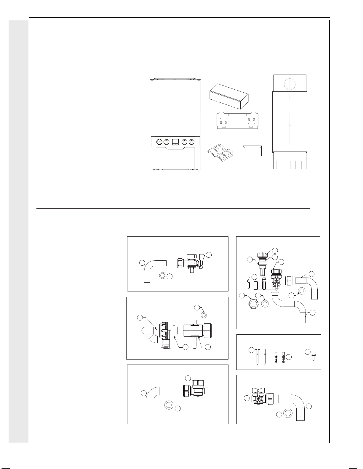
2.2 UNPACKING
The boiler is supplied fully assembled in Pack A. A telescopic or non-telescopic ue assembly for rear or side ue outlet in Pack
B is supplied as a separate order.
Unpack and check the contents.
Pack A Contents
A Boiler
B Hardware Pack Box
C Wall Mounting Plate
D These Installation/Users Instructions
E Wall Mounting Template
F Boiler Guarantee & Registration Pack
C
A
D
F
B
E
Boiler Guarantee
HARDWARE PACK CONTENTS
Gas Valve Pack
1. Pipe - Gas Inlet
2. Washer - Gas (blue)
3. Gas Cock
Filling Loop Pack
1. 3/8" Top Hat Washer
2. Valve Filling Loop
3. Pipe Filling Loop
4. Washer Fibre 3/8”
Return Valve Pack
1. Pipe CH Return
2. Washer CH
3. Valve Return
DHW Pack
1. 1/2" Top Hat Washer (x2)
2. Cap Female
3. Plug Male and Clip
4. Nut G1/2 16 Brass (Flat)
5. Washer 18.5 x 11 x 11.8 (x2)
6. Pipe DHW Outlet
7. Pipe DHW Inlet
8. Valve DHW Inlet
Accessory Pack
1. Screw (x2)
2. Wallplug (x2)
3. Turret Clamp Screw (spare)
Flow Valve Pack
1. Pipe CH Flow
2. Washer CH
3. Valve Flow
Gas Valve Pack DHW Pack
Accessory Pack
Flow Valve Pack
Return Valve Pack
Filling Loop
1
1
1
1
2
3
3
2
2
2
3
3
2
8
3
3
1 2
1
7
5
6
4
1
5
4
continued . . . . .
INSTALLATION
19
Installation and Servicing
SECTION 2 - INSTALLATION
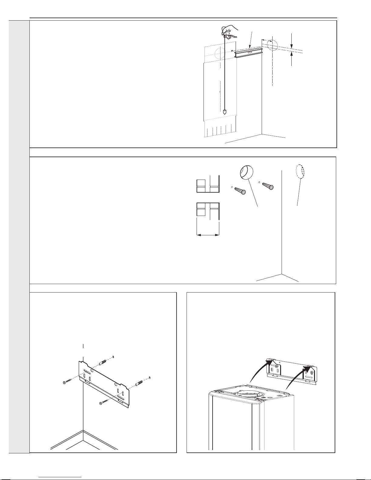
2.4 FRONT PANEL REMOVAL
1. Loosen the 2 screws retaining the front panel.
2. Pull the two clips downwards to disengage.
3. Pull the front panel forward and upwards to remove.
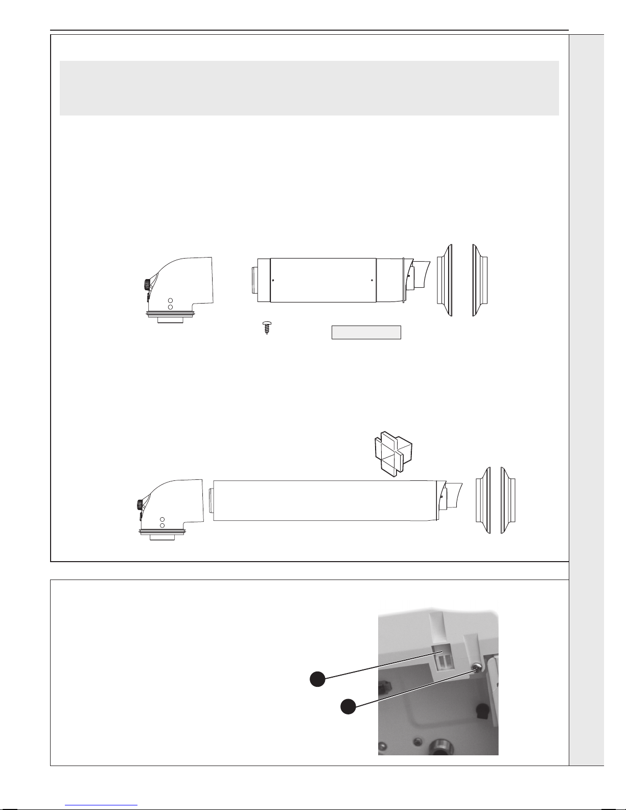
Pack B Contents Telescopic
A Telescopic Flue Terminal
B Flue Turret
C Rubber Terminal Wall Seal
D Screw
E Sealing Tape
F Wall Seal (White)
D
C
A
E
F
B
1
2
Pack B Contents Non-Telescopic
A Flue Terminal
B Flue Turret
C Rubber Terminal Wall Seal
D Cutting Aid
E Wall Seal (White)
2.3 UNPACKING CONT’D
A
D
B
CE
Note. This ue system incorporates a removable ue outlet nose that utilises a push t location system. This enables the
installation of deector, high level or balcony outlet ue kits without the removal of the whole ‘B’ pack terminal. The appliance
must not be operated without the desired outlet nose correctly tted in place.
Note. Location dimples must be aligned with terminal mounting frame.
INSTALLATION
20
Installation and Servicing
SECTION 2 - INSTALLATION
The wall mounting template is located on the internal protective
packaging. The template shows the position of the xing and rear
ue centre holes for a standard installation
Care MUST be taken to ensure the correct holes are drilled.
1. Tape template into the required position, ensuring its squareness
by hanging a plumbline as shown.
2. If tting a side ue, extend the ue centreline onto the side by
155mm on a standard wall x or 200mm if using a stand-off
bracket.
3. Mark the following on to the wall:
a The selected group of wall mounting screw holes.
b. The centre position of the ue duct. Marking both the centre
and the circumference of the ue duct.
4. Remove the template plate from the wall.
2.5 WALL MOUNTING TEMPLATE
2.6 PREPARING THE WALL
IMPORTANT.
Ensure that, during the cutting operation, masonry falling
outside of the building does not cause damage or personal
injury.
1. Cut the ue hole (preferably with a 5” core boring tool),
ensuring that the hole is square to the wall.
Both wall faces immediately around the cut hole should be
at.
2. Drill 2 mounting holes (marked from template) with a 7.5mm
/ 8mm masonry drill and insert the plastic plugs, provided,
for the wall mounting plate.
3. Locate 2 No.14 x 50mm screws in the wall mounting plate
(one at each side, in any of the 3 holes provided at each
side) and screw home. Ensure mounting bracket is level.
2.8 MOUNTING THE BOILER
1. Ensure the plastic plugs are removed from both the CH
and DHW connections before mounting the boiler.
Note. Boiler may contain residual water.
2. Lift the boiler onto the wall mounting plate (refer to the
Introduction section for safe handling advice), locating it
over the two tabs.
2.7
FITTING THE WALL MOUNTING PLATE
Screw the wall mounting plate to the wall using 2 wall plugs
(previously tted) with the 2 screws provided.
Choose one of the 2 sets of slots in left and right bank.
Ensure that at least one of the screws is tted into a top slot
and the mounting bracket is level.
A** - See Diagram in
Section 1.16
Extended centre line
155
(200)
3G9495
X
Section
through wall
Note. Check all of the hole
positions before drilling.
Side flue only
5" diameter hole
Rear flue only
5" diameter hole
esp9496
Example of fixing
INSTALLATION
21
Installation and Servicing
FLUE OUTLET
SECTION 2 - INSTALLATION
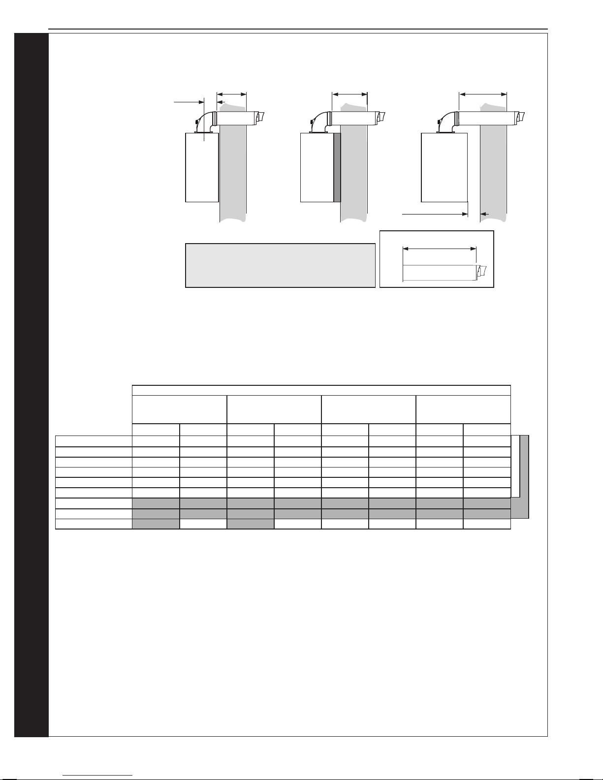
2.9 DETERMINING THE FLUE LENGTH AND FLUE PACKS REQUIRED
IMPORTANT. The boiler must be installed in a vertical position in
accordance to the installation instructions.
FLUE KITS
Telescopic Flue‘B’ Pack - contains: Flue turret, telescopic ue
incorporating a terminal and rubber wall seals.
Horizontal Flue Terminal (600mm long) ‘B’ Pack - contains: Flue
turret, non telescopic single piece ue incorporating a terminal and
rubber wall seals.
Horizontal Flue Terminal (1000mm long) ‘B’ Pack - Flue turret,
telescopic ue incorporating a terminal, rubber wall seals and
instructions.
Note. If ‘B’ packs are used on their own (either 1 piece or telescopic), then
they MUST be tted horizontally as the ue inside is designed to slope 1.5
degrees.
D Pack Flue Extension 100mm DIA 1000mm long
D Pack Flue Extension 100mm DIA 500mm long
D Pack Flue Extension 100mm Dia 2000mm long
Roof Flue Kit with Vertical Connector
When extension ‘D’ Packs are used the ue duct must incline
1.5 degrees away from the appliance, to allow the condensate
to drain back to the boiler and out of the condensate drain. It is
recommended that a support bracket is tted on every 1 metre of
pipe work used and the bracket is located as close to the collar as
possible. The bracketing must ensure a 1.5 degree fall back to the
appliance.
Optional Flue Finishing Kit - & Concentric Flue Screw Retaining
Kit (Optional Kit of mechanical xing of ue joints)
Only use water as a lubricant during assembly.
The ‘B’ pack terminal is classed as part of the maximum ue
length.
These ue systems incorporate a removable ue outlet nose that
utilises a push t location system. This enables the installation
of deector, high level or balcony ue kits without the removal of
the whole ‘B’ pack terminal. The appliance must not be operated
without the desired outlet nose correctly tted in place, ensuring
the side location dimples are in line with the mounting face allowing
the correct sealing of the components.
It is IMPORTANT that all attachments are tted in accordance to
the installation instructions provided with them.
The TURRET supplied in the ‘B’ Pack has an upper combustion
sample point with a screw cap seal and a lower air sample point
with an air stopper seal. Ensure all caps & seals are in place.
Additional Termination Kits available for use with these ‘B’ packs.
Flue Deector Kit The resistance is the equivalent of 1 metre of ue pipe and therefore must be deducted from
any maximum ue length
High Level Flue Outlet Kit
The maximum permissible concentric ue length when using a standard (500mm) kit is 4.5 metres
Balcony Flue Outlet Kit The maximum permissible concentric ue length when using this kit is dependant on the length
of the balcony ue outlet run which combined with the concentric run must not exceed the
maximum ue length requirement of the appliance it is to be tted to
Soft Kit This kit enables tment of an external ue below softs.
Total Maximum Permissible Horizontal Concentric Flue Length combining both ‘B’ Packs and ‘D’ Packs
(Measured from centreline of the turret to the outside of the wall terminal)
30 kW Appliances Total Maximum: 8 metres - minus any ue kit options or bends
35 kW Appliances Total Maximum: 6 metres - minus any ue kit options or bends
Total Maximum Permissible Vertical Flue Length combining both Roof Terminal and ‘D’ Packs
30 & 35kW Appliances Total Maximum: 7.5 Metres - minus any bends
Powered Vertical Flue
30 & 35kW Appliances Example: 5 Metres - Concentric Flue and 17m ue pipe only. For additional
congurations and details refer to the powered Vertical Instructions
90º Elbow Kit 60/100 - (Equivalent ue length resistance = 1M)
45º Elbow Kit 60/100 - (Equivalent ue length resistance = 0.6M)
Minimum Horizontal Flue Lengths (Centre line of turret to outside of wall terminal)
Telescopic Flue ‘B’ Pack = 400mm
Horizontal Flue terminal (600mm long) ‘B’ Pack = 285mm
Wall Thickness Std Metric Brick 102.5mm wide
‘B’ Pack Flue Type 60/100 Minimum Permissible Wall Thickness Maximum Permissible Wall Thickness
Rear Flue
Rear Flue + Stand-Off
Side Flue Rear Flue
Rear Flue + Stand-Off
Side Flue
Horizontal Flue Terminal
(600mm long) B Pack
126* 102.5 102.5 501 456 456
Telescopic Flue B Pack 231 186 186 429 384 384
Horizontal Flue Terminal
(1000mm long) B Pack
546 501 501 761 716 716
Horizontal Flue Terminal
(1000mm long) B Pack cut 75mm
471 426 426 686 641 641
* If wall thickness is <126 and >102.5, contact the manufacturer.
For Flue lengths between 658 & 708 use a Horizontal Flue Terminal (1000mm long) B Pack, cut 75mm off the end of the terminal
section of the telescopic ue only.
22
Installation and Servicing
FLUE OUTLET
SECTION 2 - INSTALLATION
100mm
Edge of turret
to outside face of wall plus
44mm = ue length
Centre of turret to edge of turret = 100mm
Turret has a ue insertion of 30mm
The compressed outer wall seal has protruding wall to seal mounting lip - 14mm
From centreline of turret to wall. Rear mount 155mm, side (including clearance) 200mm
NOTES
REAR
Fit
to wall
A
WALL
Edge of turret
to outside face of wall plus
44mm = ue length
Flue length measured from outer terminal lip
to end of outer ue
A + 44mm
REAR
Fit
to wall
inc. Stand
o Frame
A
WALL
Edge of turret
to outside face of wall plus
44mm = ue length
SIDE
Fit
to wall
A
WALL
Minimum clearance 5mm
....... DETERMINING THE FLUE LENGTH AND FLUE PACKS REQUIRED, CONT’D
FIGURE 1
Note. Maximum permissible
ue length is measured from
centre line of appliance ue
outlet to outside wall face.
Note; Telescopic ue B Pack or attached “D” pack extensions do not need to be cut between minimum and maximum values
shown above (except where specied). Horizontal Flue Terminal (600mm long) B Pack ue will require cutting on values
below maximum values shown in the table above.
If using the 2000mm D Pack , the maximum usable length per extension is 1950mm
If using the 500mm D Pack, the maximum usable length per extension is 450mm.
Shows the ue required when measured from outside edge of turret to the outside face of the wall (to obtain cut length add 44mm)
Minimum & Maximum nished ue lengths obtainable (dimension ‘A’ +44mm)
Horizontal Flue Terminal
(600mm long) B Pack
Telescopic Flue B Pack Horizontal Flue
Terminal (1000mm long)
B Pack (Telescopic)
Horizontal Flue Terminal
(1000mm long) B Pack
(Telescopic) Cut 75mm
Minimum Maximum Minimum Maximum Minimum Maximum Minimum Maximum
B Pack (Standard) 181 556 286 484 601 816 526 741
Plus 1 (1m D pack) 1121 1506 1236 1434 1551 1766 1476 1691
Plus 2 (1m D pack) 2071 2456 2186 2384 2501 2716 2426 2641
Plus 3 (1m D pack) 3021 3406 3136 3334 3451 3666 3376 3591
Plus 4 (1m D pack) 3971 4356 4086 4284 4401 4616 4326 4541
Plus 5 (1m D pack) 4921 5306 5036 5234 5351 5566 5276 5491
Plus 6 (1m D pack) 5871 6256 5986 6184 6301 6516 6226 6441
Plus 7 (1m D pack) 6821 7206 6936 7134 7251 7466 7176 7391
Plus 8 (1m D pack) 7771 7886
Max output 35 kW
Max output 30 kW
FIGURE 2
 Loading...