

Page 1

Hobs
ZANUSSI
OPERATING AND INSTALLATION MANUAL
2
Page 2

CONTENTS
Technical characteristics Pag. 3
General warnings Pag. 4
Instructions for user Pag. 5
Use Pag. 6
Maintenance and cleaning Pag. 7
Instructions for installer Pag. 7
Gas connection Pag. 8
Electrical connection Pag. 9
Adaption of hob burners to different types of gas Pag. 10
Insertion in kitchen units Pag. 12
Technical assistance and spareparts Pag. 15
TECHNICAL DATA
Power of gas burners
Rapid burner (large) 10,00 MJ/h
Semi-rapid burner (medium) 6,12 MJ/h
Auxiliary burner (small) 3,60 MJ/h
Appliance operation Natural Gas
L.P.G. Gas
Appliance caliber Natural Gas 1,0 kPa 25,84 MJ/h
Conversion to use with L.P.G. 2,75 kPa 25,56 MJ/h
Gas entry connection G1/2
Voltage tension 240 V 50 Hz
MANUFACTURER: ELECTROLUX ZANUSSI ELETTRODOMESTICI S.p.A.
Viale Bologna, 298
47100 FORLÌ (Italy)
3
Page 3
WARNINGS - GAS HOBS
It is most important that this instruction brochure should be kept together with the
appliance for future consultation. If the appliance is sold or transferred to another person,
ascertain that the brochure is also given, in order that the new user can be aware of the
correct use of the machine and the relative warnings.
THESE WARNINGS HAVE BEEN PREPARED FOR YOUR SAFETY AND FOR THAT
OF OTHERS, WE THEREFORE REQUEST YOU TO READ THEM CAREFULLY
BEFORE INSTALLING AND USING THE APPLIANCE.
● This appliance has been designed for use by
adults. Take care, therefore, that children do
not attempt to play with it.
● This appliance has been designed for
cooking purposes only. It must not be used
for any other purposes, or be destined to
professional or industrial use.
● Where this appliance is installed in marine
craft or in caravans, it shall not be used as a
space heater.
● The work of installation must be carried out
by competent and qualified installers
according to the regulations in force.
● The appliance must be installed at a
minimum distance of 50 cm. from curtains
or other combustible material.
● Any modifications to the domestic electrical
mains which may be necessary for the
installation of the appliance should only be
carried out by competent personnel.
● In case of repairs contact an authorized
Technical Assistance Centre and insist on
original spareparts.
● It is dangerous to modify, or attempt to modify,
the characteristics of this appliance.
● Unstable or deformed pans should not be
placed on the burners or plates in order to avoid
accidents caused by upsetting or boiling over.
● Particular care should be taken when cooking
with oil or fat.
● Burners, plates, grills and pans remain hot for
a long time after being switched off. Supervise
children at all times when in use paying
attention that they do not touch surfaces or
remain in the vicinity of the appliance when in
use or when not completely cooled.
● If the appliance is fitted with a cover, its
function is to protect the surface from dust
when closed and to accumulate splashes of
grease when open. Do not use for other
purposes.
4
● Always clean the cover before closing and
allow the burners and/or plates to cool before
closing.
● Always check that the switch is in the « »
position when the appliance is not in use.
● Ensure that air can circulate around the gas
appliance. Poor ventilation can produce a lack
of oxygen.
● Supply the appliance with the type of gas
stamped on the relevant adhesive label situated
in the immediate vicinity of the gas connection
tube.
● Before maintenance or cleaning disconnect the
appliance and allow to cool.
● Do not spray areosols in the vicinity of this
appliance while it is in operation.
● To facilitate ignition, light the burner before
placing the pan on the grill.
● After having lit the burner check that the flame
is regular.
● Always lower the flame or turn it off before
removing the pan.
● In case of repairs, do not atempt to correct
yourself. Repairs carried out by unqualified
persons can cause damage. Contact the nearest
Assistance Centre and use only original
spareparts.
The use of a gas cooking appliance
produces heat and humidity in the room in
which it is installed. Ensure good
ventilation of the room by keeping natural
ventilation openings clear or installing an
extractor hood with a discharge tube.
A prolonged and intensive use of the
appliance may necessitate supplementary
ventilation, for example the opening of a
window or a more efficient ventilation by
increasing the power of mechanical
extraction, if existing.
Page 4
INSTRUCTIONS FOR THE USER
2
1
3
6
7
8
9
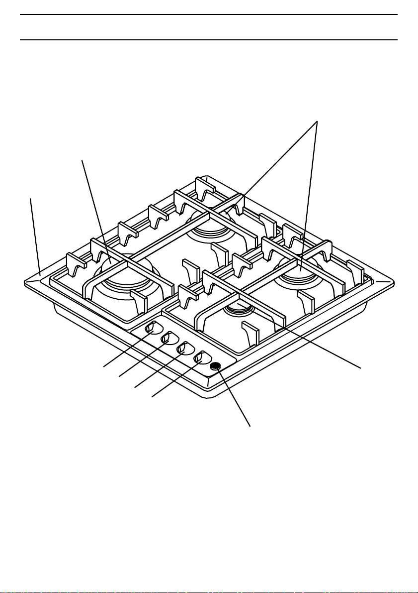
1. Hob Top
2. Rapid Burner
3. Semirapid Burners
4. Auxiliary Burner
5. Control Panel
6. Control knob for back left burner
7. Control knob for front left burner
8. Control knob for front right burner
9. Control knob for back right burner
4
5
5
Page 5
INSTRUCTIONS FOR USER
INSTALLATION
All operations relating to installation, regulation and adaption to the type of gas supplied, must be
carried out by qualified personnel, according to the regulations in force.
Specific instructions are contained in the notices reserved for the installer.
USE
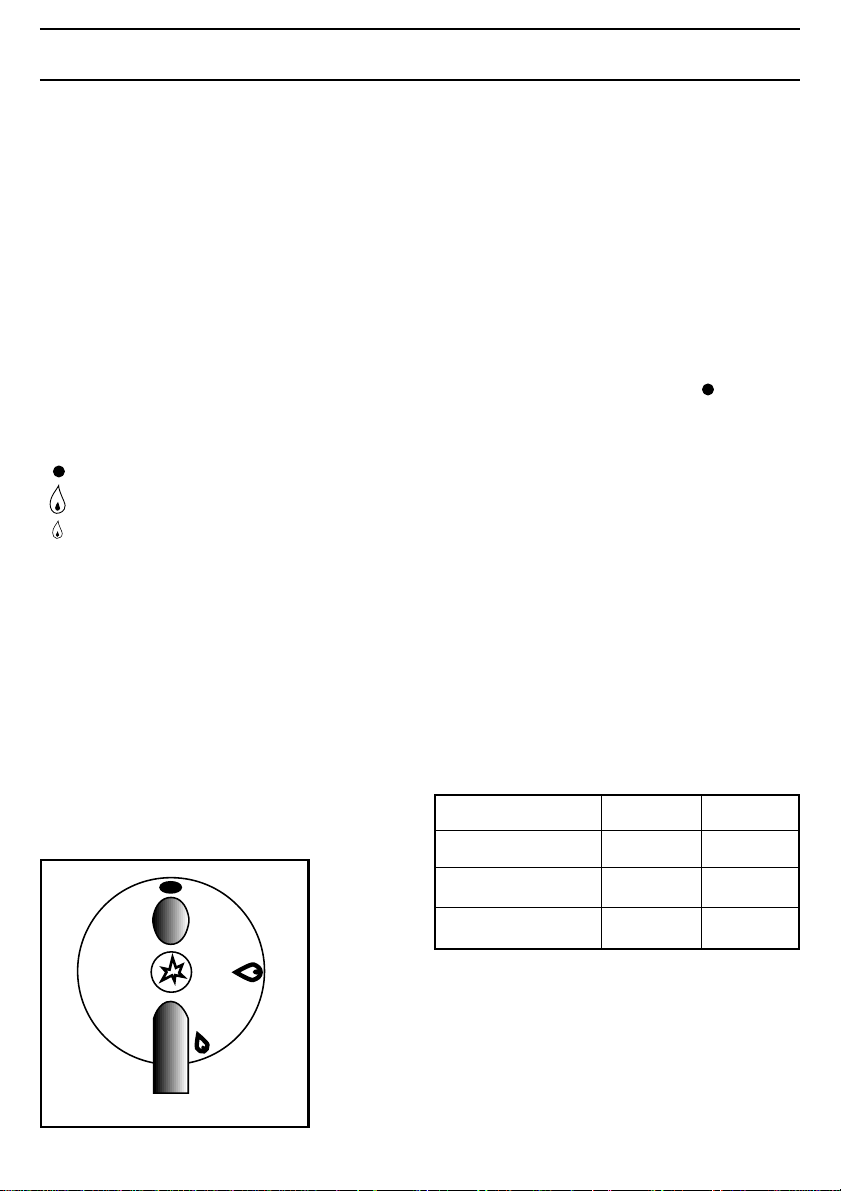
Hob control switch
The switches for the gas burners of the hob are
situated on the control panel. The regulating
switch of the burners can only be turned in an
anti-clockwise direction to the small flame sign
and vice-versa in the opposite direction.
no emission of gas
maximum emission of gas
minimum emission of gas
Ignition of burners
To ignite a burner, before positioning the
saucepan, approach with a flame, push the
corresponding switch in completely and turn in an
anti-clockwise direction to the maximum position.
Then regulate the flame as required.
In models having automatic ignition work the
appropriate button, marked by a small spark, and
then open the tap completely.
In models having a security device turn the
corresponding switch in an anti-clockwise
direction to the maximum position, press in fully
and keep pressed for approximately 5 seconds
until the security valve automatically maintains
the flame alight.
IMPORTANT
If after a few attempts the burner does not ignite,
check that the baffle and its cap are correctly
positioned.
To interrupt the supply of gas, turn the switch in a
clockwise direction to the position « ».
For a minor consumption of gas and a better
efficiency it is advisable to use pans having a
diameter suitable to the burners, as shown in the
table. It is also advisable that, as soon as a liquid
starts to boil you should lower the flame
sufficiently to maintain simmering point. In case
the burner flame accidentally goes out, close the
command switch and try to ignite again after not
less than 1 minute.
During cooking, when using fats or oils, take
particular care as they can, when over-heated,
self-ignite.
Minimum and maximum diametres of recipients
which can be placed on the burners.
Burner Min. diam. Max. diam.
Rapid (large) 160 mm 240 mm
FO 0252
6
Semi-rapid (medium) 120 mm 220 mm
Auxiliary (small) 80 mm 160 mm
Page 6

MAINTENANCE AND CLEANING
Before each operation electrically disconnect the
appliance.
Wash the enamelled parts with warm water and
detergent, do not use abrasive products which
could damage them; frequently wash the baffles
of the burners with boiling water and detergent,
taking care to remove all encrustrations; the parts
in stainless steel should be rinsed well with water
after use and dried with a soft cloth.
The hob’s enamelled grills can also be washed in
the dishwasher. For persistent marks use normal,
non-abrasive detergents or specific products
which can easily be found in commerce.
It is never advisable to use wire pads, steel wool
or acids for cleaning.
For hobs having automatic ignition periodically
carry out an accurate cleaning of the ignitor
(ceramic or electrode) to avoid ignition
difficulties, furthermore check that the baffle
holes are not obstructed.
Clean the plates with a damp cloth and lightly
grease with vegetable oil or sewing machine oil
whilst still warm.
Periodic oiling of the taps must be carried
out by qualified personnel who should also
be contacted if a fault in the functioning of
the appliance occurs.
INSTRUCTIONS FOR THE INSTALLER
ATTENTION: This appliance must be installed and used only in rooms which are permanently
The following instructions relating to installation and regulation must be carried out by qualified
personnel. The appliance must be installed correctly in conformity with the rules and regulations in
force. All interventions must be carried out with the appliance electrically disconnected.
THE MANUFACTURER DECLINES ALL RESPONSIBILITY FOR ANY DAMAGES
DERIVING FROM AN INSTALLATION WHICH DOES NOT CONFORM WITH THE
SITE OF INSTALLATION
For a good operation of the gas appliance it is
indispensable that the air necessary for gas
combustion can circulate in the room in a natural
manner. (The installer must follow the regulations
in force.)
ventilated according to the regulations in force.
REGULATIONS IN FORCE.
● The appliance must be installed at a
minimum distance of 50 cm. from curtains
or other combustible material.
7
Page 7

CONNECTION TO THE GAS SUPPLY
CONNECTION
Gas connection must be carried out in conformity
with the regulations in force. The appliance
leaves the factory tested and regulated for the
type of gas indicated on the plate which is
situated in the lower position near the gas
connection tube. Ascertain that the type of gas
with which the appliance will be supplied is the
same as that indicated on the plate.
If different carry out all the operations according
to the indications cited in the paragraph “adaption
to different types of gas”.
For a maximum output and minimum
consumption ascertain that the pressure of the gas
used has the values indicated in the table of
“burner characteristics”.
If the pressure of the gas used is different (or
variable) from that foreseen it is necessary to
install a suitable pressure regulator on the inlet
tube.
The use of pressure regulators for liquid gas
(GPL) is permitted as long as these conform to
the regulations in force.
The joint is mounted on the intake area of the
pipe, fitted with a filleted nut GJ 1/2, between the
sealing components as shown in Fig. 1. Screw the
parts without forcing, turn the joint in the
direction required and then tighten everything.
A) Intake pipe with nut
B) Seal
C) Adjustable joint
Carry out the connection to the gas plant only by
means of a rigid metallic tube conforming to the
regulations in force.
The joint for the entry of gas into the appliance is
threaded GJ 1/2".
Carry out the connection avoiding any type of
stress on the appliance.
The adjustable joint permits the location of the
supply tube in the appropriate site situated on the
side of the protection box of the hob itself (Fig.
2).
This system permits the total encumbrance of the
hob plus the gas supply tube to be contained to a
depth of 30 mm.
A) Intake pipe with nut
B) Adjustable joint
C) Rigid metallic gas supply tube
FO 0265
Fig. 2
IMPORTANT
Upon completion of installation, always check:
● that all the joints are completely sealed by
using a soapy solution, never a flame;
Fig. 1
● that the automatic ignition system is
operating satisfactory on all burners, both
individually and in combination.
8
Page 8

ELECTRICAL
CONNECTION
The appliance is predisposed to function with a
230V monophase voltage tension. Connection
must be carried out in conformity with the
regulations and dispositions of the laws in force.
Before connecting ensure that:
- The limiter valve and the electrical mains can
support the voltage of the appliance (see
registration plate).
- The power supply is correctly earthed according
to the regulations in force.
- The plug or omnipolar interrupter used can be
easily reached once the appliance has been
installed.
Fit the cable with a plug suitable to the voltage
and connect to an appropriate security socket.
If a direct connection to the mains is required, an
omnipolar interrupter with a minimum opening of
3mm between contacts, dimensioned to the
voltage and corresponding to the regulations in
force, should be interposed between the appliance
and the supply. The yellow/green earth cable must
not be interrupted by the interrupter. The brown
coloured phase cable (situated at terminal “L” of
the terminal box) must always be connected to the
network phase. The voltage cable must always be
positioned in such a manner that it at no point
reaches a temperature of 50∞C above room
temperature. An example of the best routing is
shown in fig. 3. The cable is guided by use of
clamps fixed laterally to the unit in such a way as
to avoid any contact with the appliance under the
hob.
CLAMPS
Openings
in the
{
Forniture
Unit
FO 0238-EN
YES
RIGID METALLIC TUBE
OR FLEXIBLE STAINLESS
STEEL TUBE
REAR VIEW
NO
REAR VIEW
Fig. 3
FO 0073-EN
Fig. 4
In case of substitution of the voltage cable use
cable type H05 RRF having a section suited to the
charge, it is furthermore necessary that the
yellow/green earth wire be approximately 2cm
longer than the phase and neutral wires (Fig. 4).
After connection try out the heating elements
allowing them to function for approximately 3
minutes.
The manufacturer declines all responsibility
in case the prevention of accidents regulations
are not respected.
9
Page 9

ADAPTATION TO DIFFERENT TYPES OF GAS
SUBSTITUTION OF THE
NOZZLES
Remove the grills:
Remove the caps and baffles from the burners:
With a tubular spanner no. 7 unscrew and remove
(fig. 5) the nozzles substituting them with those
corresponding to the type of gas used (see tab):
Remount the parts carrying out the operations
described in reverse. Then substitute the caliber
plate (positioned near the gas supply connection)
with the one corresponding to the new type of
gas. This can be found in the injector bag
supplied.
If the pressure of gas used is different (or
variable) from that foreseen an appropriate
pressure regulator should be installed on the entry
tube.
In case pressure regulators for GPL are used these
should conform to the regulations in force.
REGULATION OF THE
MINIMUM
Fig. 5
To regulate the minimum bring the tap to the
minimum flame position.
Extract the knob.
If the tap is of a type with the pin by-pass inside
the bar (Fig. 6-8), it is sufficient to screw or
unscrew according to the type of gas as indicated
in the following paragraph.
If the tap is of a type with a lateral by-pass (Fig.
8) it is necessary to detach the command panel by
applying pressure to the lateral projection (Fig. 7),
then insert a screwdriver through the hole until
the pin is reached.
When transforming from methane gas to GPL gas
fully screw down the by-pass pin.
Finally check that by quickly turning the tap from
the maximum position to the minimum position
the burner is not extinguished; remount the parts
carrying out the operations described in reverse.
The above-described adaption operations can be
easily carried out whatever the positioning or
fixture of the hob to the kitchen unit.
10
Fig. 6
FO 0254
Fig. 7
TAP
Burner Ø By-pass
Auxiliary 28
Semi-rapid 35
Rapid 45
of tap
1/100 mm
Page 10

Fig. 8
a) minimum
regulation
screw
b) normal tap
c) valvular tap
FO 1045
Fig. 9
TYPE TYPE NOZZLE NOMINAL REDUCED
OF GAS OF BURNER MARKS THERMAL THERMAL
1/100 mm CAPACITY CAPACITY kPa
MJ/h MJ/h
NATURAL
GAS
(methane)
L.P.G.
GAS
Rapid (large) 140 10,00 2,34
Semi-rapid (medium) 111 6,12 1,51 1,0
Auxiliary (small) 89 3,60 0,90
Rapid (large) 88 9,72 2,34
Semi-rapid (medium) 71 6,12 1,51 2,75
Auxiliary (small) 55 3,60 0,90
MAINTENANCE
Periodically control the state of conservation and
efficiency of the gas tube and, if present, the
pressure regulator; in case of irregularity do not
attempt to repair, but substitute the damaged part.
To guarantee good functioning and security the
gas regulation taps should be periodically
greased.
The periodic lubrification of the taps must
be carried out by qualified personnel who
should also be contacted in case
irregularities are encountered in the
functioning of the apparatus.
NOMINAL
PRESSURE
11
Page 11

INSTALLATION IN THE KITCHEN UNITS
DIMENSIONS
Height (overall): 74 mm. (see drawing)
Depth: 510 mm.
Width: 580 mm.
Thickness: 30 mm.
Automatic Taps
Ignition Switches: YES
Gas Hob Burners: 1 Rapid Burner (front left)
1 Auxiliary Burner (front right)
2 Semirapid Burners (back)
12
30
SR
554
SR
A
R
13
13
510
16,5
477
CUT OUT DIMENSIONS
Height: 72 mm.
Depth: 480 mm.
Width: 560 mm.
Weight: 9 Kg.
74
510
480
580
560
580
FO 0767
Fig. 10
A = Auxiliary Burner
SR = Semirapid Burner
R = Rapid Burner
12
16,5
FO 0697
Fig. 11
Page 12

INSERTION AND ASSEMBLY
The hobs can be installed in a unit having an
opening for installation of the dimensions
illustrated in fig. 11.
The fixture of the hob to the unit must be carried
out as follows:
position the appropriate sealings, supplied, on the
edge of the opening predisposed taking care that
the edges meet without overlapping;
place the hob in the opening of the unit taking
care in centring;
fix the hob to the unit by means of the appropriate
clips (see fig. 12). The traction of the screws is
sufficient to trace the seal, whose excess can thus
be removed. The edge of the hob forms a double
labyrinth seal which provides a total guarantee
against the infiltration of liquids.
POSSIBILITY FOR INSERTION
Kitchen unit with door
Suitable precautions should be taken in the
construction of the unit in order to avoid possible
contact with the hot surround of the hob when in use.
This could occur if the hob surround is affected by a
depression or pressure following the opening or
closing of the door. The solution recommended to
avoid this inconvenience is illustrated in Fig. 14.
The panel under the hob should be easily removable
in order to permit blocking and unblocking of the hob
for technical assistance purposes.
The opening for insertion must be distant from the
base and the side, of a minimum of 55 millimetres for
the rear fig. 18.
60
Fig. 14
a) Seal
Fig. 13
30
Fig. 12
480
30
a
20 min
b
a) Panel of
380
dismantled
591
140
unit
b) Possible
space
useful for
FO 1013
connections
FO 1038
Fig. 15
13
Page 13

Kitchen unit with oven
The opening should have the dimensions shown in figs. 13-14 and be provided with supports to permit
an efficient ventilation. To avoid excessive overheating it is advisable to carry out installation as (figs.
16-17). The electrical connection of the hob and that of the oven must be carried out separately, both for
electrical reasons and to facilitate the frontal extraction of the oven.
2
120 cm
2
50 cm
FO 0939
180 cm
2
Fig. 16 Fig. 17
FO 0938
360 cm
2
MINIMUM DISTANCE TO BE RESPECTED
(in millimetres)
55 MIN.
650 mm
FO 0805
Fig. 18
FO 0479
Fig. 19
In case of a right or left side having a height exceeding that of the hob, this should be situated at a
minimum of 100mm from the top opening. Cupboards or extractor fans should be situated at a minimum
of 650mm from the hob (Fig. 19).
14
Page 14

TECHNICAL ASSIST ANCE AND SP ARE P ARTS
Before leaving the factory this appliance was
tested and controlled by expert and specialized
personnel in order to give the best working
results. All repairs or controls which may be
necessary should be undertaken with maximum
care and attention.
For this reason we recommend you always
contact the Retailer who sold it or our nearest
Assistance Centre, specifying the type of problem
and the model of the appliance in your
possession.
The Manufacturer is not responsible for possible inaccuracies, caused by printing or
transcription errors, contained in the present manual. It reserves the right to make any
modifications to its products which it deems necessary or useful, even in the interest of the
user, without prejudizing essential operating and security characteristics.
Important!
This appliance is easy to use. Nonetheless,
to obtain the best results it is important that
this brochure be read carefully and all the
instructions followed before using for the
first time.
The brochure provides the correct
indications for installation, use and
maintenance as well as providing useful
advice.
15
 Loading...