

Page 1

Cher Client,
vous venez d’acheter un de nos produits et nous vous en remercions vivement.
Nous sommes certains que ce nouvel appareil, moderne, fonctionnel et pratique, réalisé avec des
matériaux de toute première qualité, saura vous donner entière satisfaction. L’utilisation est très
simple; nous vous conseillons cependant de lire attentivement cette notice avant de l’utiliser pour
obtenir les meilleurs résultats possibles.
Le fabricant décline toute responsabilité en cas de dommages aux personnes et aux
choses dus à une installation incorrecte ou à une mauvaise utilisation de l’appareil.
Le fabricant ne répond pas des inexactitudes de cette notice imputables à des erreurs d’impression ou de
transcription. De même, l’esthétique des figures représentées dans cette notice n’a qu’une valeur indicative.
Toujours soucieux d’améliorer nos produits, nous nous réservons le droit d’apporter toute modification utile
ou nécessaire dans l’intérêt de l’utilisateur, sans compromettre les caractéristiques essentielles de
fonctionnement et de sécurité.
COD. 01075SM (01075FR) - 28.05.2001
INSTRUCTIONS ET CONSEILS POUR
L’EMPLOI, L’INSTALLATION ET
L’ENTRETIEN DES TABLES DE CUISSON
ENCASTRABLES ÉLECTRIQUES
36
-VI
Page 2
14
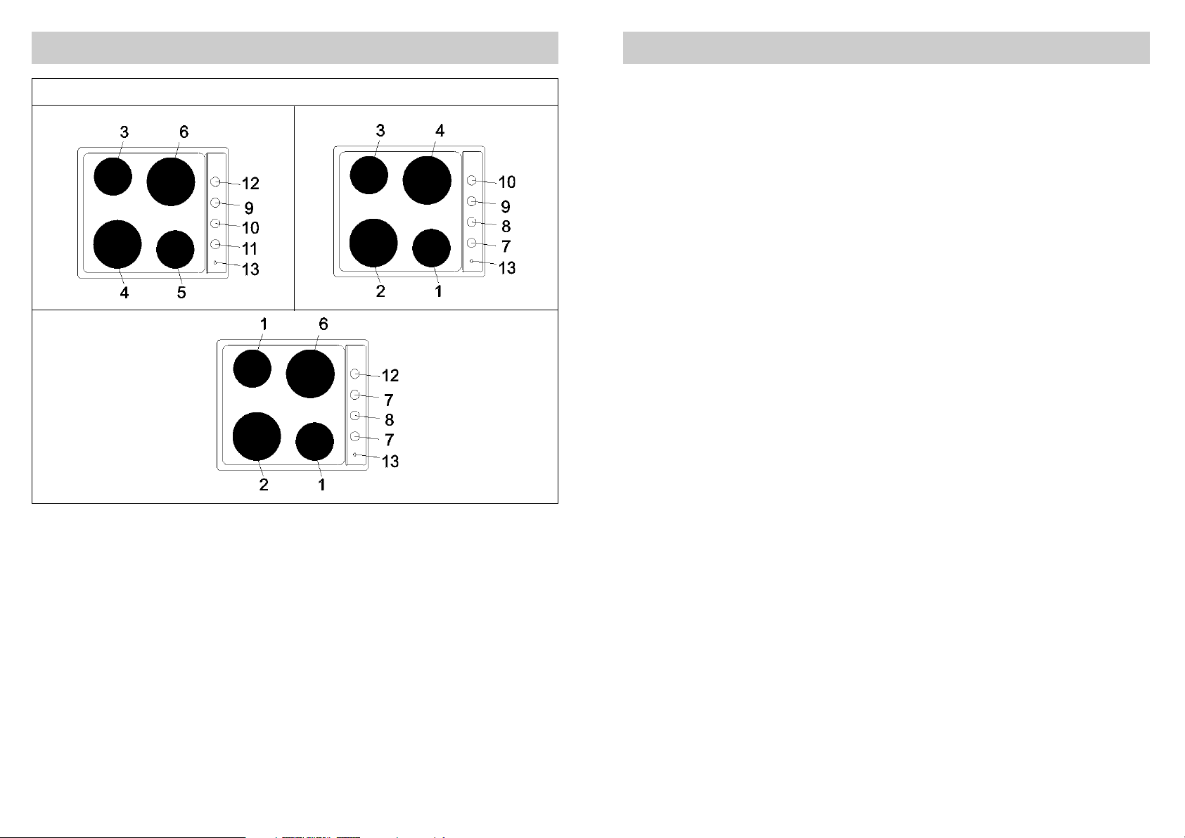
1 Foyer de cuisson normale Ø 145 de 1000 W
2 Foyer de cuisson normale Ø 180 de 1500 W
3 Foyer de cuisson rapide Ø 145 de 1500 W
4 Foyer de cuisson rapide Ø 180 de 2000 W
5 Foyer de cuisson thermostatique Ø 145 de 1500 W
6 Foyer de cuisson thermostatique Ø 180 de 2000 W
7 Manette de commande foyer de cuisson n° 1
8 Manette de commande foyer de cuisson n° 2
9 Manette de commande foyer de cuisson n° 3
10 Manette de commande foyer de cuisson n° 4
11 Manette de commande foyer de cuisson n° 5
12 Manette de commande foyer de cuisson n° 6
13 Voyant qui signale l’insertion d’un ou plusieurs foyers de cuisson
DESCRIPTION DES TABLES DE CUISSON
TYPE: PAZ04
35
TECHNICAL ASSISTANCE AND SPARE PARTS
This appliance, before leaving the factory, has been carefully tested and regulated by expert and
specialized personnel in order to guarantee the best performances.
Any repairs or adjustments which may be subsequently required may only be carried out by qualified
personnel with the utmost care and attention.
For this reason, always contact your Dealer or your nearest After Sales Centre whenever repairs or
adjustments are required, specifying the type of fault and the model of appliance in your possession.
Please also note that genuine spare parts are only available from our After Sales Service Centres and
authorized retail outlets.
The above data are printed on the data label put on the inferior part of the appliance and on the packing
label.
The above informations give to the technical assistant the possibility to get fit spare parts and a heavensent intervention. We suggest to fill the table below.
MARK:.............................……….
MODEL:...........................……….
SERIES:...........................……….
Page 3
15
EMPLOI
1) INSERTION DES FOYERS
ÉLECTRIQUES
Les tables électriques peuvent être équipées de
trois types de foyers de cuisson: foyers de cuisson
normales, thermostatiques et rapides (disque rouge
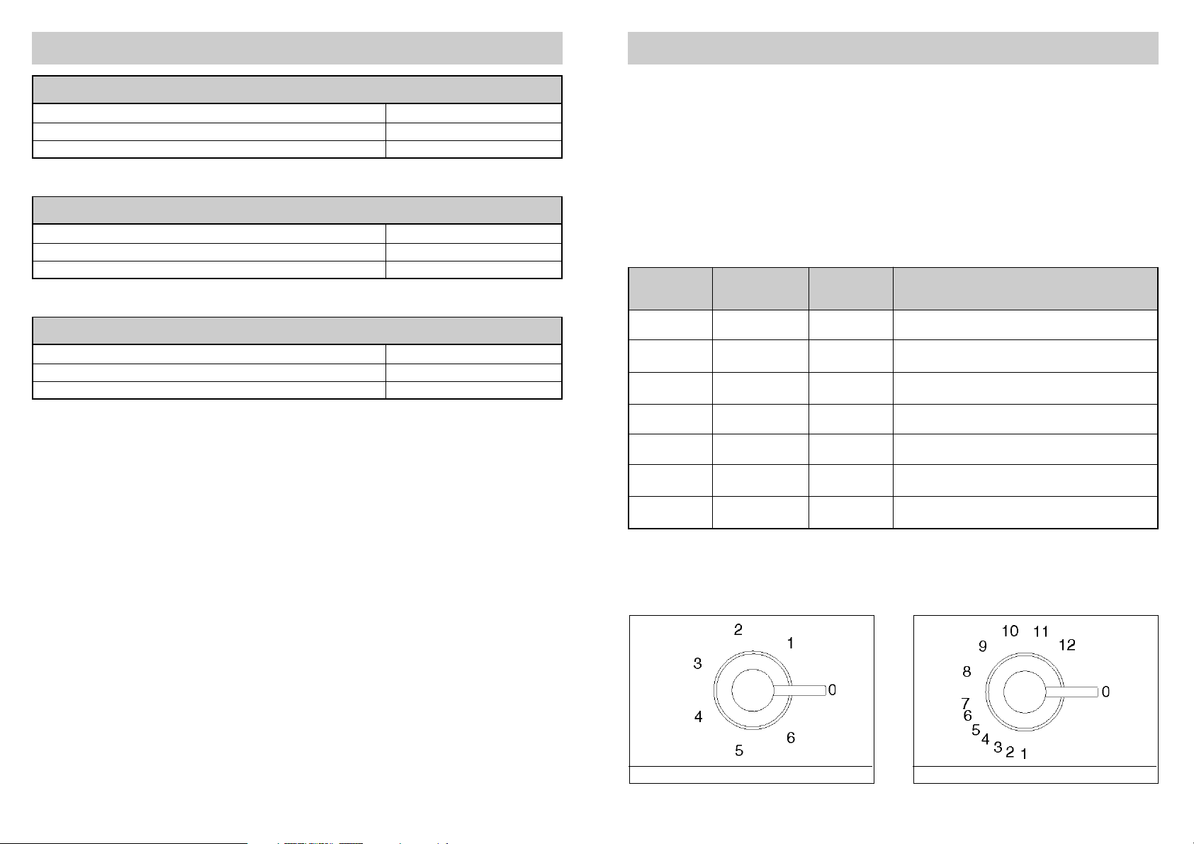
au centre). Les foyers de cuisson normales et
rapides sont commandés par un commutateur à 7
positions (voir fig. 1). Les foyers de cuisson
thermostatiques sont commandés par un
commutateur à 12 positions (voir fig.2). Pour les
faire fonctionner, tournez la manette jusqu’à la
position désirée.
Sur le bandeau, vous trouverez gravé, à côté de
chaque manette, un schéma qui indique le foyer à
lequel la manette se réfère (voir fig. 1 - 2).
Un voyant lumineux rouge indique le
fonctionnement d’un ou plusieurs foyers de cuisson.
2) COMMENT UTILISER LES FOYERS
ÉLECTRIQUES
À titre purement indicatif, dans le tableau cidessous, nous expliquons comment utiliser les
foyers de cuisson.
FIG. 1 FIG. 2
0 Éteinte
1 1 Délicat
2 1 - 4 Feu doux
3 4 - 8 Lent
4 8 - 10 Moyen
5 10 - 12 Fort
6 12 Feu vif
FOYERS FOYERS INTENSITÉ TYPES DE CUISSON
NORMALES
THERMOSTATIQUES
DE CHALEUR POSSIBLES
ET RAPIDES
TABLEAU
Faire fondre le beurre, le chocolat, etc.; chauffer de
petites quantités de liquide.
Chauffer des quantités moyennes de liquide;préparer
des crèmes et des sauces à longue cuisson.
Décongeler les aliments surgelés et mijoter, cuire à
la température d’ébullition ou à peine plus basse.
Faire cuire des aliments nécessitant l’ébullition, rôtis
de viandes delicates et poissons.
Rôtis, côtelettes, bifteck et pot-au-feu.
Faire bouillir de grandes quantités de liquide et frire.
VOLTAGE 230 - 240 V~
FREQUENCY 50/60 Hz
TOT. RATING 7000 W
MODEL WITH
2 RAPID PLATES + 2 THERMOSTAT PLATES
VOLTAGE 230 - 240 V~
FREQUENCY 50/60 Hz
TOT. RATING 6000 W
MODEL WITH
2 RAPID PLATES + 2 NORMAL PLATES (with protector)
VOLTAGE 230 - 240 V~
FREQUENCY 50/60 Hz
TOT. RATING 5500 W
MODEL WITH
3 NORMAL PLATES (with protector) + 1 THERMOSTAT PLATE
34
TECHNICAL DATA
Page 4
16
EMPLOI
AVERTISSEMENTS:
Lors de la première utilisation ou si vous n’avez pas utilisé le foyer depuis longtemps, faitez fonctionner
le foyer pendant 30 minutes (position 1 du commutateur) pour éliminer l’humidité absorbée par le matériau
isolant.
Pour utiliser correctement votre table de cuisson rappelez-vous de:
- Mettre l’appareil sous tension uniquement après avoir posé la casserole sur le foyer.
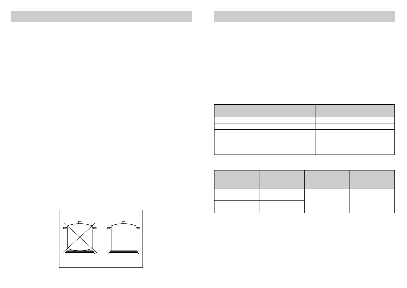
- Utiliser des casseroles à fond plat et épais (voir fig. 3).
- Ne pas utiliser de casseroles plus petites que le foyer.
- Essuyer le fond de la casserole avant de la poser sur le foyer.
- Ne pas s’éloigner de l’appareil pendant la cuisson et faire attention que les enfants ne s’en approchent
pas. Assurez-vous que les manches des casseroles sont tournés vers l’intérieur et surveillez la
cuisson lorsque vous utilisez de l’huile et des graisses qui sont facilement inflammables.
- Après l’utilisation, le foyer reste chaud longtemps; ne posez pas les mains ou tout autre objet pour éviter
de vous brûler.
- Si la table de cuisson est doté d’un couvercle, avant de l’ouvrir, éliminer tous les résidus d’aliments
debordés sur sa surface. Si l’appareil reviendra doué d’un couvercle en verre, il pourrait éclater lorsqu’il
est chauffé. Éteindre et laisser refroidir les foyers avant de fermer le couvercle.
- Débrancher l’appareil dès que vous remarquez des fêlures sur la surface du foyer de cuisson.
FIG. 3
33
SERVICING
Always disconnect the appliance from the
electricity main before proceeding with any
servicing operation.
8) REPLACING THE ELECTRICAL
COMPONENTS
For access to the various parts, remove the hotplate
from the top of the cabinet. Then overturn it, unscrew
screw “Z” and remove under part. (see fig. 9).
After these actions is possible to work on the
plates, commutators, clamps and input cable.
N.B. In case of substitution of the input
cable, the installer must keep the “earth”
conductor longer than “live” ones, and must
respect the cautions in paragraph
“Electrical connection”.
To reassemble the appliance repeat the inverse
process.
9) TECHNICAL CHARACTERISTICS OF
THE ELECTRICAL COMPONENTS
To facilitate the job of the installer we present a
scheme with the characteristics of the components.
POWER OF ELECTRICAL COMPONENTS DENOMINATIONS W
Normal plate Ø 145 mm – 7 positions with the protector 1000
Normal plate Ø 180 mm – 7 positions with the protector 1500
Rapid plate Ø 145 mm – 7 positions 1500
Rapid plate Ø 180 mm – 7 positions 2000
Thermostat plate Ø 145 mm – 12 positions 1500
Thermostat plate Ø 180 mm – 12 positions 2000
Denominations W
TYPE AND SECTION OF THE POWER CABLES
Rubber
3 X 1.5 mm2(*)
5 X 1.5 mm2(*) 4 X 1.5 mm2(*)
H05 RR-F
Polycroropene
3 X 2.5 mm
2
(*)
H05 RN-F
Single phase Three phase Three phase
Cable type
power power 400 V 3N ~ power
230 - 240 V~ 400 - 415 V 3N~ 400 - 415 V 2N~
(*) keeping in mind the contemporaneousness factor
Page 5

17
NETTOYAGE
ATTENTION:
Débranchez l’appareil du réseau d’alimentation
électrique avant toute opération de nettoyage.
3) PLAN DE CUISSON
Pour conserver la surface du plan de cuisson
brillant, lavez-le avec de l’eau tiède et du savon
chaque fois que vous l’utilisez, rincez-le et
essuyez-le.
Ne nettoyez pas le plan lorsque les foyers de
cuisson sont encore chauds. N’utilisez pas
d’éponges métalliques, de poudres abrasives ou
de spray corrosifs.
Éliminez toute trace de vinaigre, café, lait, eau
salée et jus de citron ou de tomate le plus
rapidement possible.
AVERTISSEMENTS:
- Pour conserver la surface des foyers de
cuisson propre et brillante, nettoyez-les
chaque fois que vous les utilisez avec les
produits spécifiques en vente dans le
commerce. Cette opération est nécessaire et
évitera qu’ils ne s’oxydent (rouille).
- L’éventuel liquide débordé dès casseroles, doit
être toujours enlevé avec un chiffon.
32
CONVERSIONS
Disconnect the appliance from the mains
supply prior to any conversions being carried
out.
7) CHANGING THE TYPE OF POWER
SUPPLY
Although they leave our factory preset for singlephase connection, certain appliances may by
converted to the threephase system.
Comply with the following instructions:
a) Remove the hotplate from the top of the cabinet,
overturn it, unscrew screw "Z" and remove under
part (see fig. 9).
b) Shift connecting plate on terminal according to
the following chart. This chart is also affixed to the
hob.
c) Insert a supply cable of adequate section (see
chart par. 10) through core hitch on the terminal
board.
d) Connect the phase and earth wires to the relative
terminal board.
e) Fix the supply cable in place using clamp.
f) Refit the hotplate, complying with the above
instructions in reverse.
FIG. 9 FIG. 10
Page 6

18
INSTALLATION
L’installation et les opérations d’entretien
mentionnées dans ce chapitre sont réservées
à des techniciens qualifiés.
Une mauvaise installation peut entraîner des
accidents aux personnes, aux animaux ou aux
choses, auquel cas le fabricant ne saurait être
considéré comme responsable.
4) MISE EN PLACE DE LA TABLE DE
CUISSON
Après avoir retiré l’emballage extérieur et les
protections intérieures enveloppant les différentes
parties mobiles, assurez-vous que l’appareil est en
bon état. En cas de doute, n’utilisez pas l’appareil
et adressez-vous à un technicien qualifié.
Ne laissez pas les éléments de l’emballage
(carton, sachets, polystyrène expansé, clous,
etc....) à la portée des enfants car ils
représentent un danger potentiel.
Effectuez une ouverture d’encastrement sur le
meuble en respectant les dimensions de la fig. 4 et
en vous assurant d’avoir respecté les dimensions
critiques de l’espace dans lequel l’appareil doit
être installé (voir fig. 5).
Si un manteau aspirant est installé dessus au plan
de cuisson, faire réference à la distance minime
spécifiée par le constructeur du manteau (fig. 5).
5) FIXATION DE LA TABLE
La table de cuisson est livrée avec un joint spécial
évitant l’infiltration de liquide dans le meuble. Pour
monter ce joint, respectez rigoureusement les
instructions suivantes:
- Ôtez les rubans du joint de leur support en vous
assurant que la protection transparente reste
accrochée au joint.
- Renverser la table et placez correctement le joint
“E” (fig. 6) sous le bord du plan de sorte que
l’extérieur du joint corresponde exactement avec
le contour du plan. Les deux bouts des rubans
doivent se rencontrer sans être superposés.
- Collez soigneusement le joint sur le plan en
appuyant dessus avec les doigts.
- Retirez le film de protection du joint, enfilez les
brides dans les logements “K” sur la table et
installez la table dans l’ouverture préparée sur le
meuble puis bloquez-la à l’aide des vis “F” de
fixation (voir fig. 7).
ATTENTION:
Le collant qui fixe le revêtement plastique au
meuble doit résister à une température
minimale de 150° C pour éviter que le
revêtement ne se décolle.
Avis à l’installateur: l’appareil est de type Y. Le
panneau arrière, adjacentes et celles qui
entourent la table de cuisson doivent résister à
un échauffement de 65 K.
FIG. 4 FIG. 5 FIG. 6
FIG. 7
31
INSTALLATION
FIG. 8
6) ELECTRICAL CONNECTIONS
Electrical connection must be carried out in
compliance with the specifications and
provisions in force.
Before proceeding with the connections, check that:
- The voltage rating of the appliance and the
current sockets suits the maximum power draw
of the appliance (see data label affixed to the
lower part of the appliance itself).
- The system is equipped with an efficient earth
connection in compliance with the pertinent
provisions in force. The manufacturer declines all
responsibility for failure to comply with these
provisions.
- If the appliance has no power cable, connect a
cable of adeguate section to the terminal strip
(consult the table on next page) complying with
the wiring diagram of fig. 8. This diagram is also
affixed to the hot plate.
When connection to the electricity main is
made by using a socket (gas version only):
- Fit a standard plug to power cable (if supplyied).
This plug should be able to bear the load
indicated on the data label. Connect the wires
according to the diagram in fig. 8, remembering
to comply with the following instructions:
letter L (live) = brown wire;
letter N (neutral) = blue wire;
earth symbol = yellow-green wire.
- The powering cable must be positioned so that it
is never able to reach an overtemperature of 75 K
in any part.
- Never use reductions, adapters or shunts for the
connection since these could cause false
contacts and dangerous overheating.
When the appliance is connected straight to
the electricity main:
- Install an omnipolar cutout between the
appliance itself and the main. This circuit-breaker
should be sized according to the rating of the
appliance and the opening between its contacts
should be at least 3 mm.
- Remember that the earth wire must not be cutout
by the switch.
- Alternatively, the electrical connection may also
be protected by a high sensitivity differential
switch.
Installers are strongly advised to connect the
yellow- green earthing wire to an efficient earthing
system.
The manufacturer cannot be responsible for the
missing earthing of the appliance.
WARNINGS:
All our appliances are designed and
manufactured in compliance with European
standards EN 60 335-1 and EN 60 335-2-6
plus the relative amendments.
The appliance complies with the provisions
of the following EEC Directives:
- CEE 89/336 + 92/31 + 93/68 regarding to
electromagnetic compatibility.
- CEE 73/23 + 93/68 regarding electrical
safety.
Page 7

19
INSTALLATION
FIG. 8
6) BRANCHEMENT ÉLECTRIQUE
Le raccordement au réseau d’alimentation doit
être effectué conformément aux normes et
aux dispositions de la loi en vigueur.
Avant d’effectuer le raccordement, vérifiez:
- L’aptitude de l’installation et des prises de
courant par rapport à la puissance maxi de
l’appareil (voir étiquette signalétique apposée en
bas du caisson).
- Que la prise ou l’installation ont été correctement
reliées à une prise de terre, conformément aux
normes et aux dispositions de la loi en vigueur.
Le fabricant décline toute responsabilité en cas
de non respect de ces normes.
- Si l’appareil n’est pas doté du câble
d’alimentation, branchez un câble de section
adéquate (voir tableau nelle pages suivantes) à
la boîte à bornes en vous assurant que le
conducteur de mise à la terre est plus long que
les conducteurs de phase et en suivant le
schéma fig. 8.
Dans le cas de raccordement au réseau
d’alimentation effectué au moyen d’une prise:
- Montez (si besoin est) une fiche normalisée sur
le câble d’alimentation “C” en vous assurant
qu’elle est adaptée à la charge indiquée sur
l’étiquette signalétique. Branchez les
conducteurs en suivant le schéma, fig. 8 et en
respectant les indications suivantes:
Lettre L (phase) = conducteur marron;
Lettre N (neutre) = conducteur bleu;
Symbole (terre) = conducteur vert-jaune.
- Placez le câble d’alimentation de sorte qu’il ne
soit jamais exposé à un échauffement de 75 K.
- N’utilisez pas de réductions, adaptateurs ou
dérivations car ils pourraient provoquer de faux
contacts et des échauffements qui pourraient
s’avérer dangereux.
Dans le cas de raccordement direct au réseau
d’alimentation électrique:
- Interposez un disjoncteur onnipolaire entre
l’appareil et l’alimentation, dimensionné en
fonction de la charge de l’appareil et dont
l’ouverture minimum entre les contacts dépasse
3 mm.
- Le câble de terre ne doit pas être interrompu par
le disjoncteur.
- En alternative, le raccordement électrique peut
également être protégé par un disjoncteur
différentiel à haute sensibilité.
Il est vivement recommandé de brancher le câble
de terre vert-jaune à une installation de mise à la
terre efficace.
Dans le cas de manquée mise à la terre de
l’appareil, l’entreprise ne reponde pas d’éventuels
dommages.
AVERTISSEMENTS:
Tous nos appareils ont été conçus et réalisés
conformément aux normes européennes
EN 60 335-1 et EN 60 335-2-6 et aux
amendements respectifs.
L'appareil est conforme aux prescriptions des
Directives Europénnes:
- CEE 89/336 + 92/31 + 93/68 concernantes la
compatibilité électromagnétique.
- CEE 73/23 + 93/68 concernantes la sécurité
électrique.
30
INSTALLATION
Installation and maintenance must only be
carried out by a qualified installer.
Incorrect installation could cause damage to
persons, animals and property for which the
manufacturer cannot be held responsible.
4) INSTALLING THE HOT PLATE
Check that the appliance is in a good condition
after having removed the outer packaging and
internal wrappings from around the various loose
parts. In case of doubt, do not use the appliance
and contact qualified personnel.
Never leave the packaging materials
(cardboard, bags, polystyrene foam, nails,
etc.) within children's reach since they could
become potential sources of danger.
The measurements of the opening made in the top
of the modular cabinet and into which the hot plate
will be installed are indicated in either fig. 4, comply
with the measurements given for the hole into which
the appliance will be recessed (see fig. 5).
If a wood is installed above the hob, please look at
the hood manufacturer instructions regarding the
minimum distance between hood and hob (fig. 5).
5) FIXING THE HOT PLATE
The hob has a special seal which prevents liquids
from infiltrating into the cabinet. Strictly comply
with the following instructions in order to correctly
apply this seal:
- Detach the seals from their backing, checking
that the transparent protection still adheres to the
seal itself.
- Overturn the hob and correctly position seal “E”
(fig. 6) under the edge of the hob itself, so that
the outer part of the seal itself perfectly matches
the outer perimetral edge of the hob. The ends of
the strips must fit together without overlapping.
- Evenly and securely fix the seal to the hob,
pressing it in place with the fingers.
- Remove the strip of protective paper from the
seal “F” it the hooks into their relative housings
“K” in the unit and set the hob into the hole in the
cabinet. Lock it in place with the relative fixing
screws “F” (see fig. 7).
WARNINGS:
Be aware that the glue that join the
laminated plastic to the furniture, has to
resist to temperature not below 150° C, to
avoid the unstuck of the panelling.
The installer should bear in mind that the
mixed appliance is the Y type. The rear wall,
adjacent and surrounding surfaces must
therefore be able to withstand an
overtemperature of 65 K.
FIG. 4 FIG. 5 FIG. 6
FIG. 7
Page 8

20
ADAPTATIONS
Avant tout adaptations, coupez le courant à
l’appareil. .
7) ADAPTATION DU TYPE D’ALIMENTATION
Les tables de cuisson qui quittent nos usines sont
prévues pour le raccordement monophasé mais il
est tout à fait possible de les alimenter avec des
systèmes triphasés en les adaptant.
Pour ce faire, procédez de la façon suivante:
a) Enlevez la table du meuble, renversez-la, dévissez
les vis “Z” et retirez le caisson (voir fig.9).
b) Déplacez les cavaliers de raccordement sur la
boîte à bornes en suivant le schéma de la fig. 10
apposé sur le caisson de la table de cuisson.
c) Enfilez le câble d’alimentation dans le passe-câble
(vérifiez la section sur le tableau, paragraphe 10).
d) Branchez les conducteurs de phase et de terre à
la boîte à bornes.
e) Bloquez le câble d’alimentation avec le serrecâble.
f) Remontez la table en reprendant les opérations
ci-dessus dans l’ordre inverse.
FIG. 9 FIG. 10
29
CLEANING
IMPORTANT:
Always disconnect the appliance from the
electricity main before carrying out any
cleaning operation.
3) HOTPLATE
If you want to preserve the surface clean and bright,
periodically wash the hot plate with lukewarm soapy
water.
Following this, all parts should be thoroughly rinsed
and dried. Never wash them while they are still
warm and never use abrasive powders.
Do not allow vinegar, coffee, milk, salted water,
lemon or tomato juice from remaining in contact
with the enamelled surfaces for long periods of time.
WARNINGS:
- Correctly preserve the plate after use by
treating it with special products, easily
available on the market. This will keep the
surface of the plate clean and bright. The
operation will also prevent the formation of
rust.
- Any liquid overflowed the pans, must be
always remove with a rag.
Page 9

21
ENTRETIEN
Débranchez l’appareil du réseau d’alimentation
avant d’effectuer toute opération d’entretien.
8) REMPLACEMENT DES COMPOSANTS
Pour remplacer les composants installés à
l’intérieur de la table, enlevez cette dernière du
meuble, renversez-la, dévissez les vis “Z” et retirez
le caisson (voir fig. 9).
Après avoir effectué les opérations ci-dessus, vous
pouvez intervenir sur les foyers, les commutateurs,
la boîte à bornes et le câble d'alimentation.
N.B. Pour remplacer le câble d’alimentation,
l’installateur devra prévoir un conducteur de
terre plus long par rapport aux conducteurs de
phase et respecter les recommandations du
paragraphe “BRANCHEMENT ÉLECTRIQUE”.
Pour remonter l’appareil, répéter les opérations
susnommés en sens contraire.
9) CARACTÉRISTIQUES TECHNIQUES
DES COMPOSANTS ÉLECTRIQUES
Pour faciliter la tâche de l’installateur, nous fournissons
un tableau rassemblant les caractéristiques des
composants.
PUISSANCES DES COMPOSANTS ÉLECTRIQUES
Foyer normale Ø 145 mm avec protecteur à 7 positions 1000
Foyer normale Ø 180 mm avec protecteur à 7 positions 1500
Foyer rapide Ø 145 mm à 7 positions 1500
Foyer rapide Ø 180 mm à 7 positions 2000
Foyer thermostatique Ø 145 mm à 12 positions 1500
Foyer thermostatique Ø 180 mm à 12 positions 2000
Désignation W
TYPE ET SECTION DES CÂBLES D’ALIMENTATION
H05 RR-F 3 X 1.5 mm2(*) 5 X 1.5 mm2(*) 4 X 1.5 mm2(*)
H05 RN-F 3 X 2.5 mm2(*)
Type de câble Alimentation Alimentation Alimentation
monophasée Triphasée Triphasée
230 - 240 V~ 400 - 415 V 3N~ 400 - 415 V 2N~
(*) En tenant compte du coefficient de simultanéité
28
USE
WARNINGS:
When the plate is switched on for the first time, or if it has remained unused for a long period, it
should be dried for 30 minutes on switch position n° 1. This will eliminate any moisture that may
have been absorbed by the insulating material.
To correctly use the appliance, remember:
- To place a pan on the plate before switching this on.
- To always use pans with flat and very thick bottoms (see fig. 3).
- To never use pans that are smaller than the plate diameters.
- To dry the bottom of the pan before placing it on the plate.
- Correctly preserve the plate after use by treating it with special products, easily available on the
market. This will keep the surface of the plate clean and bright. The operation will also prevent
the formation of rust. Never allow children to play near the appliance when using the plates. Check
that the pan handles are positioned correctly. The user should never leave the appliance
unattended when cooking with easily inflammable oil and fat.
- The plates will remain hot for a long period of time even after use. Never touch them with the hands
or other objects in order to prevent scorching.
- If the appliance has a glass lid, this could shatter when the cooker becomes hot. Always
disconnect all the plates before closing the lid.
- Immediately disconnect the appliance from the electricity main as soon as cracks are noted on
the surfaces of the plates.
FIG. 3
Page 10

TENSION 230 - 240 V~
FRÉQUENCE 50/60 Hz
PUISSANCE TOTALE NOMINALE 7000 W
MODÈLE AVEC
2 FOYERS RAPIDES + 2 FOYERS THERMOSTATIQUES
TENSION 230 - 240 V~
FRÉQUENCE 50/60 Hz
PUISSANCE TOTALE NOMINALE 6000 W
MODÈLE AVEC
2 FOYERS RAPIDES + 2 FOYERS NORMALES (avec protecteur)
TENSION 230 - 240 V~
FRÉQUENCE 50/60 Hz
PUISSANCE TOTALE NOMINALE 5500 W
MODÈLE AVEC
3 FOYERS NORMALES (avec protecteur) + 1 FOYER THERMOSTATIQUE
22
DONNÉES TECHNIQUES
27
USE
1) SWITCHING ON THE ELECTRIC
PLATES
The hobs may be equipped with three types of
electric plates: normal, thermostat and rapid plates
indicated by a red mark. The normal plates and the
rapid plates are controlled by a 7 - position switch
(see fig. 1). The thermostat plates are controlled by
12 - position switch (see fig. 2).
Switch on the plates by turning the knob to the
required position.
A diagram is screen-printed on the front panel. This
diagram indicates to which electric plate the knob in
question corresponds (see fig. 1 - 2).
A red warning light will come on to indicate that the
plate has been ignited.
2) HOW TO USE THE ELECTRIC PLATES
A purely indicative plate regulation chart is given
below.
FIG. 1 FIG. 2
0 Off
1 1 Weak
21 - 4Low
3 4 - 8 Slow
4 8 - 10 Medium
5 10 - 12 Strong
6 12 High
NORMAL AND THERMOSTAT HEAT POSSIBLE COOKING
RAPID PLATE PLATE INTENSITY PROCESSES
TABLE
To dissolve butter, chocolate, etc.. To heat small
amounts of liquid.
To heat larger amounts of liquid.To prepare cremes
and suces requiring long slow cooking times.
To thaw frozen foods and prepare stews, heat to
boiling point or simmer.
To heat foods to boiling point.To brown delicate meats
and fish.
For escalopes and steaks.To simmer large amounts
of food.
To bring large amounts of liquid to the boil. For frying.
Page 11

23
SERVICE APRÈS-VENTE ET PIÈCES DÉTACHÉES
Avant de quitter l’usine, cet appareil a été testé et mis au point par des techniciens qualifiés et spécialisés
afin d’en obtenir les meilleurs résultats de fonctionnement.
Les pièces détachées d’origine sont disponibles exclusivement auprès de nos centres de service aprèsvente et dans les magasins autorisés.
S’il s’avère nécessaire de réparer ou transformer l’appareil, faites appel à un technicien qualifié qui puisse
vous garantir la qualité du travail.
Pour cette raison, nous vous recommandons de vous adresser toujours au Revendeur ou à notre service
après-vente le plus proche en précisant la marque, le modèle, le numéro de série de votre appareil et le
type d’inconvénient. Vous trouverez ces données gravées sur l’étiquette signalétique collée en bas de
l’appareil et sur l’étiquette collée sur l’emballage.
Ces informations permettent à nos services après-vente de trouver les pièces détachées appropriées et
d’intervenir le plus rapidement possible. Pour avoir toujours ces données à portée de main, nous vous
conseillons de les inscrire ici :
MARQUE : ...................................
MODÈLE : ...................................
SÉRIE: .........................................
26
1 Normal plate Ø 145 of 1000 W
2 Normal plate Ø 180 of 1500 W
3 Rapid plate Ø 145 of 1500 W
4 Rapid plate Ø 180 of 2000 W
5 Thermostat plate Ø 145 of 1500 W
6 Thermostat plate Ø 180 of 2000 W
7 Control knob for electric plate n° 1
8 Control knob for electric plate n° 2
9 Control knob for electric plate n° 3
10 Control knob for electric plate n° 4
11 Control knob for electric plate n° 5
12 Control knob for electric plate n° 6
13 Warning light indicating that one or more plates are operating
DESCRIPTION OF THE HOT PLATES
TYPE: PAZ04
Page 12

24
-VI
Dear Customer,
Thank you for having purchased one of our products.
We are certain that this new, modern, functional and practical appliance, built with the very
highest quality materials, will meet your requirements in the best possible way. This hob is easy to
use. It is, however, important to thoroughly read the instructions in this handbook in order to
obtain the best results.
The manufacturer shall not be held responsible for any damages to persons or
property caused by incorrect installation or use of the appliance.
The Manufacturer shall not be held responsible for any inaccuracies in this handbook due to printing or
transcription errors; the designs in the figures are purely indicative.The Manufacturer also reserves the right
to make any modifications to the products as may be considered necessary or useful, also in the interests of
the user, without jeopardizing the main functional and safety features of the products themselves.
COD. 01075SM (01075UK) - 28.05.2001
INSTRUCTIONS AND ADVICE FOR THE
USE, INSTALLATION AND MAINTENANCE
OF BUILT-IN ELECTRIC HOBS
 Loading...