

Page 1
GERMANY
SIZE : A5
MATERIAL : GREEN READ PAPER 75 G.
PLASTIC BAG : 7 x 11 INCH
PART NO. 7901-281995
PART NAME : MANUAL MET 60
REV.00
PRODUCT CODE : MET 60 : 113H-227300
This water heater must be installed (water and electrical installation), commissioned and serviced by
approved service technicians in accordance with these instructions.
MET 60
Instantaneous water heater
Operation and installation instructions
Page 2
2
L
N
115 mm
50 mm
min. 4,5 mm
max. 5,5 mm
4 x 35 mm
6 mm
6 mm
170 mm.
80 mm.
220 mm.
Fig 1
Fig 2
Fig 3
Fig 4
Fig 5
1. Installation instructions for the user and the qualitied installer
Page 3
3
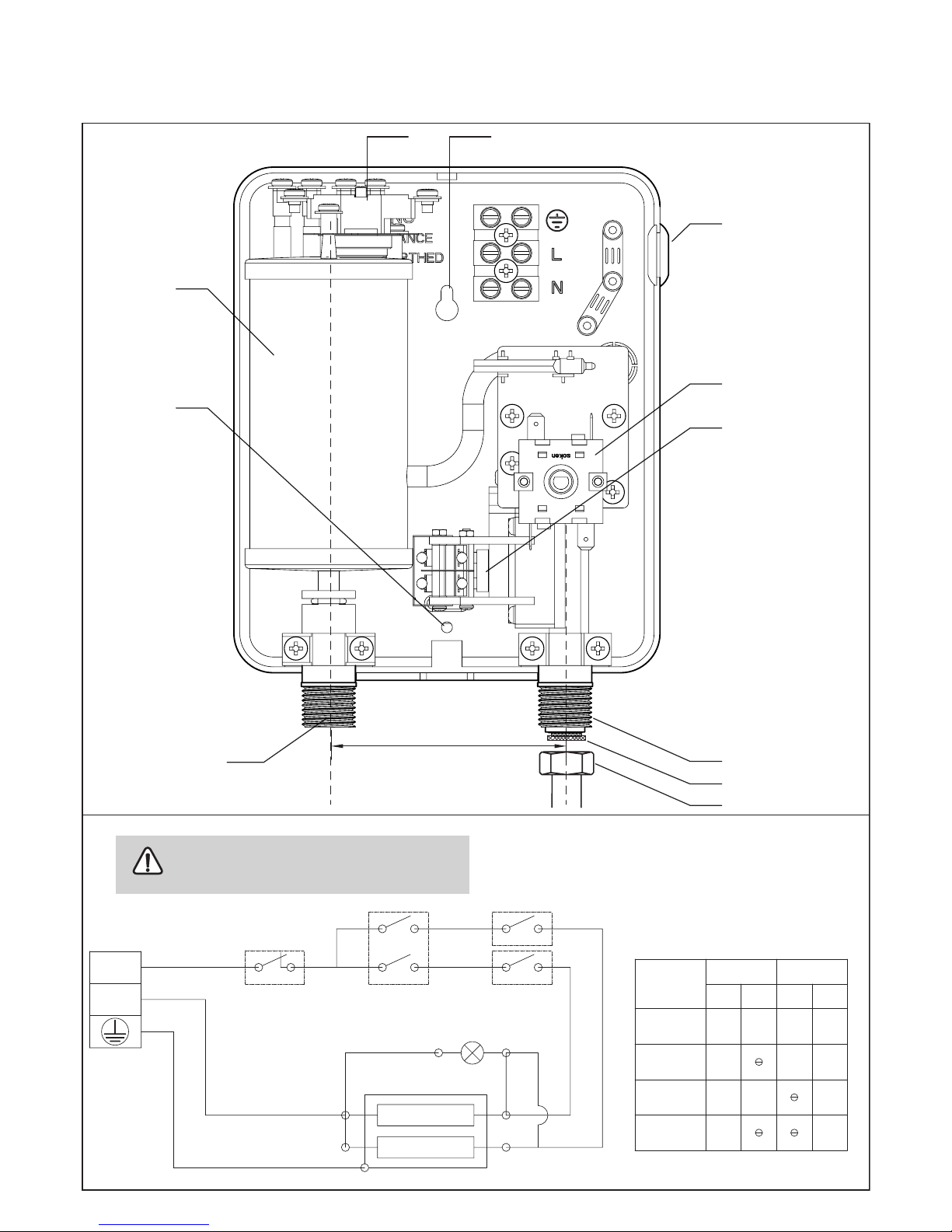
Warning:
As with any electric appliance, failure to electrically
ground unit may result in serious injury or death.
L
N
Manual re-set
Thermal cut-out
The Position Tabel
Selector Switch 4 Step
Micro Switch
Heating Elements
Selector Switch
4 Step
Lamp
POSITION
OFF
MID
LOW
HIGH
AB
1234
A
3
2
B
1 8
10
7
1
3
4
5
9
6
2
90 mm.
Fig 6
Fig 7
Page 4

4
1.1 Description of the unit
This manual must be read carefully before attempting to install
the mini multipoint water heater. If you do not follow the
safety rules or the instructions outlined in this manual, the unit
may not operate properly and it could cause property damage,
serious body injury and/or death.
ZANKER will not be liable for any damages because of failure to
comply with the installation and operating instructions outlined in
this manual or because of improper use. Improper use includes
the use of this appliance to heat any liquid other than water.
Failure to comply with the installation and operating instructions or improper use voids warranty. Never remove the unit’s
plastic cover unless the electricity is turned off.
If you have any quesions regarding the installation or operation
of this water heater, or if you need an additional installation
manual, please call our technical service line and we will refer
you to a qualified ZANKER service representative in your area.
General
The Mini Multipoint water heater does not store hot water.
Instead, water is heated instantaneously as it flows through
the unit.
The input of heat into the water is electronically controlled.
Please set the desired temperature using the knob on the front
cover. The LED lights up when the unit is “ON”.
1.2 Detail description (Fig 6)
1. Fixing hole (2 nos.)
2 Cable seal
3. Step switch
4. Differential pressure switch assembly
5. Cold water connection
9. Hot water connection
7. Water container assembly
8. Thermostat
9. Filter
10. Union nut (provided by client)
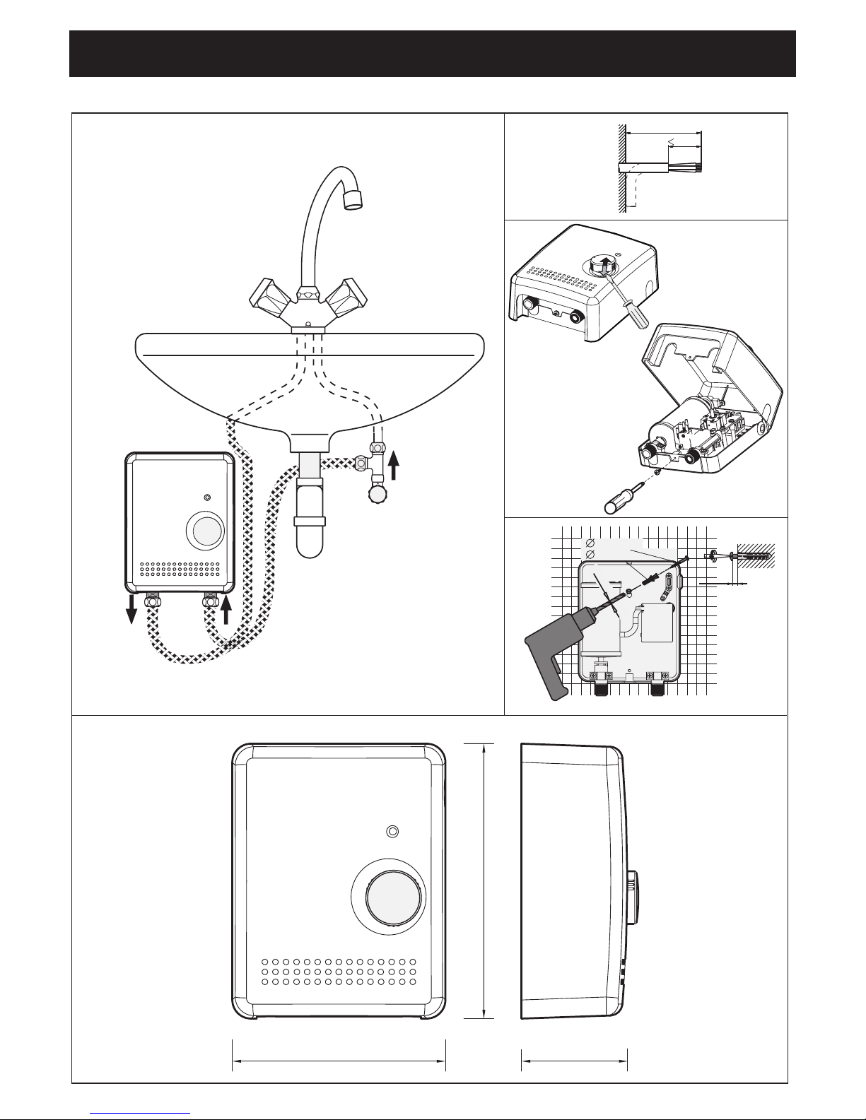
1.3 Installation instruction for the qualitified installer
1. Install the Mini Multipoint as close as possible to the
main hot water draw-off points.
2. Leave a minimum of 5” of clearance on all sides for
servicing.
3. Remove plastic cover. (Fig 3)
4. Mount unit securely to wall by putting two screws
through mounting holes. Screws and plastic wall plugs
for mounting are provided. (Fig 4)
Water connections
1. All plumbing work must comply with national and
applicable state and local plumbing codes.
2. Make certain that the cold water supply line has been
flushed to remove any scale and dirt.
3. Cold water connection (inlet) is on the right side of the
unit (Fig 6 # 5), hot water connection (outlet) is on the
left side of the unit. (Fig 6 # 6)
5. When all plumbing work is completed, check for leaks
and take corrective action before proceeding.
Unit must be installed in a vertical position with the
water fittings pointing downward. Do not install unit
where it would routinely be splashed with water. Electric
shock may result.
1.4 Electrical connection
1. All electrical work must comply with national and ap
plicable state and local electrical codes.
2. The Mini Multipoint should be connected to a properly
grounded dedicated branch circuit of proper voltage
rating. In installation with several Mini Multipoint units,
each unit requires an independent circuit.
3. The “live” wires must be connected to the slots on the
terminal block marked L. The ground wire must
be connected to the slot marked with the ground
symbol.
4. Reinstall plastic cover.
Warning:
Before begining any work on the electric installation,
be sure that main breaker panel switch is, “OFF” to avoid any
danger of electric shock. All mounting and plumbing must be
completed before proceeding with electrical hook-up where
required by local, state or national electrical codes the circuit
should be equipped with a “Ground fault interrupter”.
1.5 Regulations and Provisions
- Regulations of the local power supply company should be
observed.
- Regulations of the water supply company should observed
- Technical data.
- Install the unit flush with the wall.
- Electrical connection to be secure.
- The device must be capable of being isolated from the mains,
for example by fuses, with an isolating distance of at least
3 mm, in all poles.
The unit must be earthed (see circuitdiagram). To protect
against water penetration, the cable seal (3) must be used.
1.6 Important note
All the information in these Operating
and Installation
Instructions must be
carefully followed. These instructions
provide
important details regarding the safety, operation,
installation, and maintenance of the unit.
1.7 Installation location
The unit is to be installed in a closed,
frost-free room
(disconnected units are to be stored in a frost-free
location, since there will always be some water left in the unit)
The MET 60 is to be installed vertically on a wall (hot water
connection downwards).
1. Installation instructions for the user and the qualitied installer
Page 5

5
Warning :
Open hot water faucet for a few minutes
until water flow
is continuous and all air is purged from water pipes.The unit’s
plastic cover must be installed before the circuit breaker is
turned on.
Handing over the unit
Explain to the user how the unit works and familiarise him or
her with its use.
- Advise the user about possible hazards (high water
temperature)
- Hand over these instructions, to be kept in a safe place.
1.9 Service note
When carrying out any work, isolate the unit from the
mains and shut off the water connection.
- Clean the filter
Disconnect the union nut, remove washer , filter and clean.
Re-assemble in reverse order.
1.10. Warning
When selecting the temperature at the draw off fitting,
high water temperatures may be reached. Children,
especially, should be kept from the fitting due to the risk of
scalding.
System design Closed
Rated pressure 10 bar/1.0Mpa
Nominal capacity L. ≤ 0.25
Dimension (H x W x D) mm. 220 x 170 x 80
Weight (empty) kg. 1.4
Electrical connection 1/N/PE~220...230 V.
Power Regulating device 4 steps control (Off - Low - Med - High)
Rated power (kW) - Rated current (A) kW - A
220 V 6.0 - 27.3
230 V 6.6 - 28.7
Reccommended circuit breaker (A) 30
Reccommended cable size (Sqmm.) 6.0
Water connections (surface installation) G ½”
Technical data
MET 60
Page 6

6
For guarantees please refer to the respective terms and
conditions of supply for your country.
The installation, electrical connection and rst
operation of this appliance should be carried out by
a qualied installer.
The company does not accept liability for failure of any
good supplied which have not been installed and operated in
accordance with the manufacturer’s instructions.
2.1 Important information
- Currently-applicable data on the supply rating plate.
- Install the unit flush with the wall.
- Piped supplementary heating is not permissible.
- Water installation material. Cold water : pipe-steel or copper.
Hot water : pipe-copper.
- Electrical connection to permanently installed leads via
circuit breaker.
- Fitting for open-outlet units are not permitted.
- Safety valves are not required.
Additional Safety.
If for any reason, excessive heating occurs the manual reset
thermal cut-out will cut off the power permanently
* Customer must call for service from a qualified technician.
2.2 Putting the water heater into operation
1. Turn on circuit breaker to bring electrical power to the unit.
2. Adjust the water temperature to the desired level using the
knob on the front cover of the unit.
3. Turn on hot water and wait twenty seconds until
temperature has stabilized.
4. Check the water temperature with your hand and make sure
that it does not feel too hot. Reduce if necessary.
5. Explain to the user how the unit works and familiarize him
or her with its use.
Advise the user about possible hazards. Hand over these
instructions, to be kept for future reference.
Warning:
Open hot water faucet for a few minutes until water
flow is continuous and all air is purged from water pipes. The
unit’s plastic cover must be installed before the circuit breaker
is turned on.
Normal maintenance
The Mini Multipoint water heater is designed for a very long
service life. Actual life expectancy will vary with water quality
and use. The unit itself does not require any regular maintenance. However, to ensure consistent water flow, it is recommended to periodically remove scale and dirt that may build
up at the aerator of the faucet or in the shower head.
2.3 Care and Maintenance
All that is needed for cleaning the housing is a damp cloth. Do
not use any abrasive cleaning agents or agents containing
solvents.
Maintenance work may only be carried out by a
qualified technician.
2. Operating instructions for the user and the qualitied installer
3. Guarantee
Fault
No hot water
Water not hot enough
Cause
- circuit breaker o
- safety thermal cut-out tripped
- water ow too high
- voltage too low
Rectication
- turn circuit breaker on
- reset thermal cut-out
- reduce water ow rate
- supply correct voltage to unit
4. Fault elimination for the user
Page 7

Page 8

GERMANY
 Loading...