

Safety Emergency Stop Relay SR3D
User Information
Correct Use
Function
SR3D is an all-purpose emergency stop device which ensures the
quick and safe deactivation of the moving parts of a machine in
case of danger.
Applications for the SR3D include single or dual-channel emergency stop circuits and guard monitoring on machines and
plants.
The SR3D is specially designed and certified for the use in
furnaces and ancillary equipment in continuously mode according to EN 50156-1 and EN 746-2 and the use on ships, cetified
by Germanischer Llloyd.
•
3 safety contacts
1 auxiliary contact
•
Connection of:
•
- Emergency stop buttons
- Safety switches
- Non-contact safety switches
- OSSD-Outputs
•
Control: single or dual channel
•
Feedback loop for external contactors or extension
modules
•
Redundancy and cyclical monitoring
•
Diversified forcibly guided output relays
•
LED indicator for status channel 1 and 2
The emergency stop safety switching device SR3D is
designed for safe isolation of safety circuits according to
EN 60204-1 and can be used up to safety category 4, PL e
according to EN ISO 13849-1.
The internal logical system closes the safety contacts
when the start button is pressed.
If the safety switch is opened, the positively driven safety
contacts are opened and safely switch the machine off. It
is ensured that a single fault does not lead to a loss of the
safety function and that every fault is detected by cyclical
self-monitoring no later than when the system is switched
off and switched on again.
Errors and technical changes reserved
Germanischer Lloyd
Zertifikat TAE00003JF
•
2 start performances:
- monitored manual start
- automatic start
•
Short-circuit monitoring and earth fault monitoring
•
Up to PL e, SILCL 3, category 4
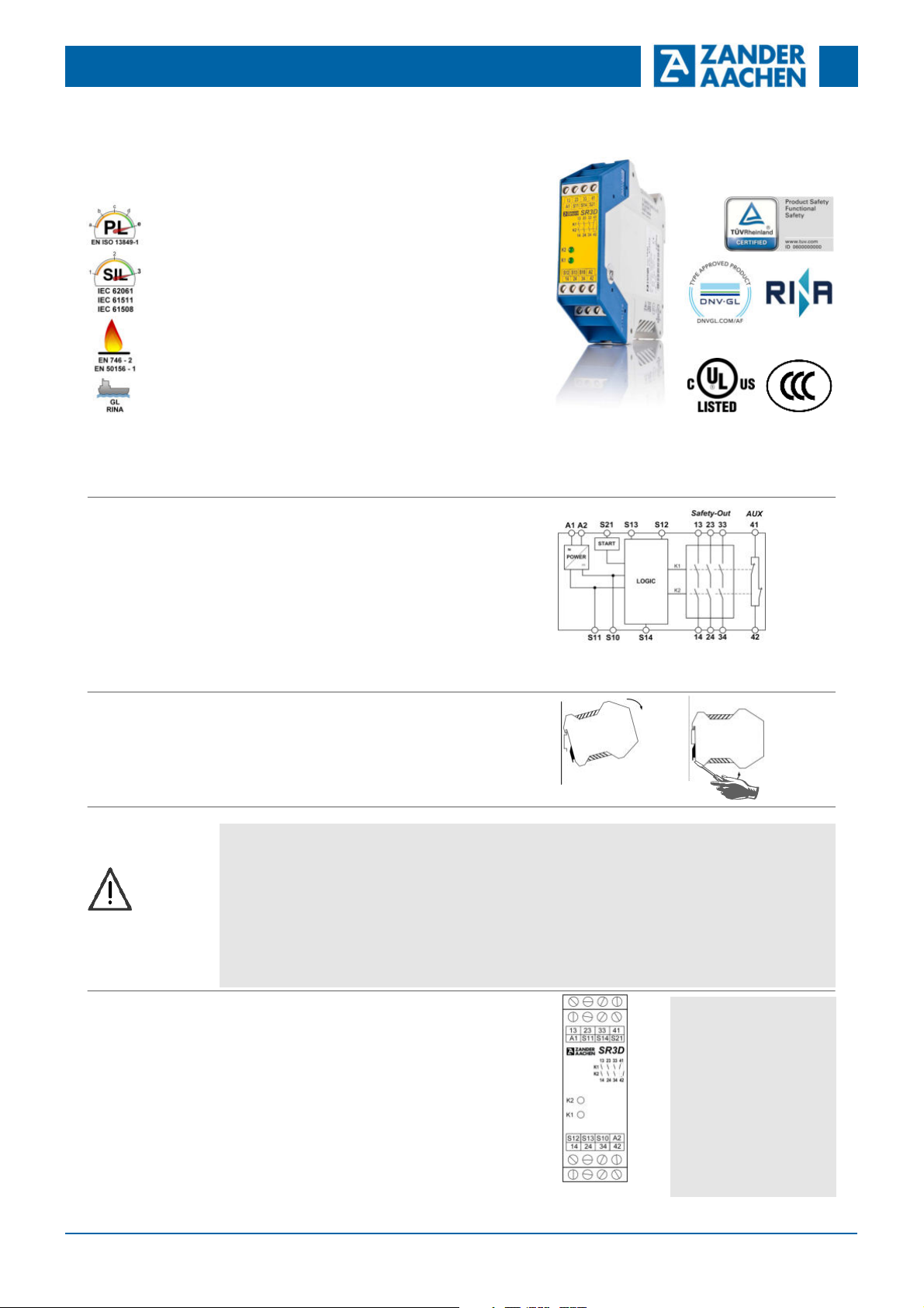
Fig. 1 Block diagram SR3D
English translation
Installation
Safety
Precautions
Electrical
Connection
As per EN 60204-1, the device is intended for installation
in control cabinets with a minimum degree of protection of
IP54. It is mounted on a 35 mm DIN rail according to
DIN EN 60715 TH35.
For the AC 115V/230V type, keep a minimum space of
10mm between the devices.
•
Installation and commissioning of the device must be
performed only by authorized personnel.
•
Observe the country-specific regulations when installing
the device.
•
The electrical connection of the device is only allowed to
be made with the device isolated.
•
The wiring of the device must comply with the instructions in this user information, otherwise there is a risk
that the safety function will be lost.
•
It is not allowed to open the device, tamper with the
device or bypass the safety devices.
•
Consider the information in the section "Techn. data"
•
When the 24 V version is used, a safety transformer
according to EN 61558-2-6 or a power supply unit with
electrical isolation from the mains must be connected
•
External fusing of the safety contacts must be provided.
•
If the device does not function after commissioning, it
must be returned to the manufacturer unopened. Opening the device will void the warranty
•
Increasing service life if driving inductive loads by using
appropriate protective circuitry (e.g. freewheeling diode)
Fig. 2 Mounting / Demounting
•
All relevant safety regulations and standards are to be
observed.
•
The overall concept of the control system in which the
device is incorporated must be validated by the user.
•
Failure to observe the safety regulations can result in
death, serious injury and serious damage.
•
Note down the version of the product (see label “Ver.”)
and check it prior to every commissioning of a new device. If the version has changed, the overall concept of
the control system in which the device is incorporated
must be validated again by the user.
A1: Power supply
A2 : Power supply
S11: DC 24 V control voltage
S10: Control line
S21: Start control line
S13: Control line
S14: Control line
S12: Control line
Ver. B
Pwr: AC/DC 24V
Fig. 3 Terminals
13-14: Safety contact 1
23-24: Safety contact 2
33-34: Safety contact 3
41-42: Auxiliary contact
Note:
Fig. 3 shows the AC/DC 24 V variant.
M03
Ver. B
E61-139-00
H. ZANDER
GmbH & Co. KG • Am Gut Wolf 15 • 52070 Aachen • Germany
Tel +49 (0)241 9105010 • Fax +49 (0)241 91050138 • info@zander-aachen.de • www.zander-aachen.de
1
Safety Emergency Stop Relay SR3D
User Information
Applications
Emergency Stop
Circuit
Errors and technical changes reserved
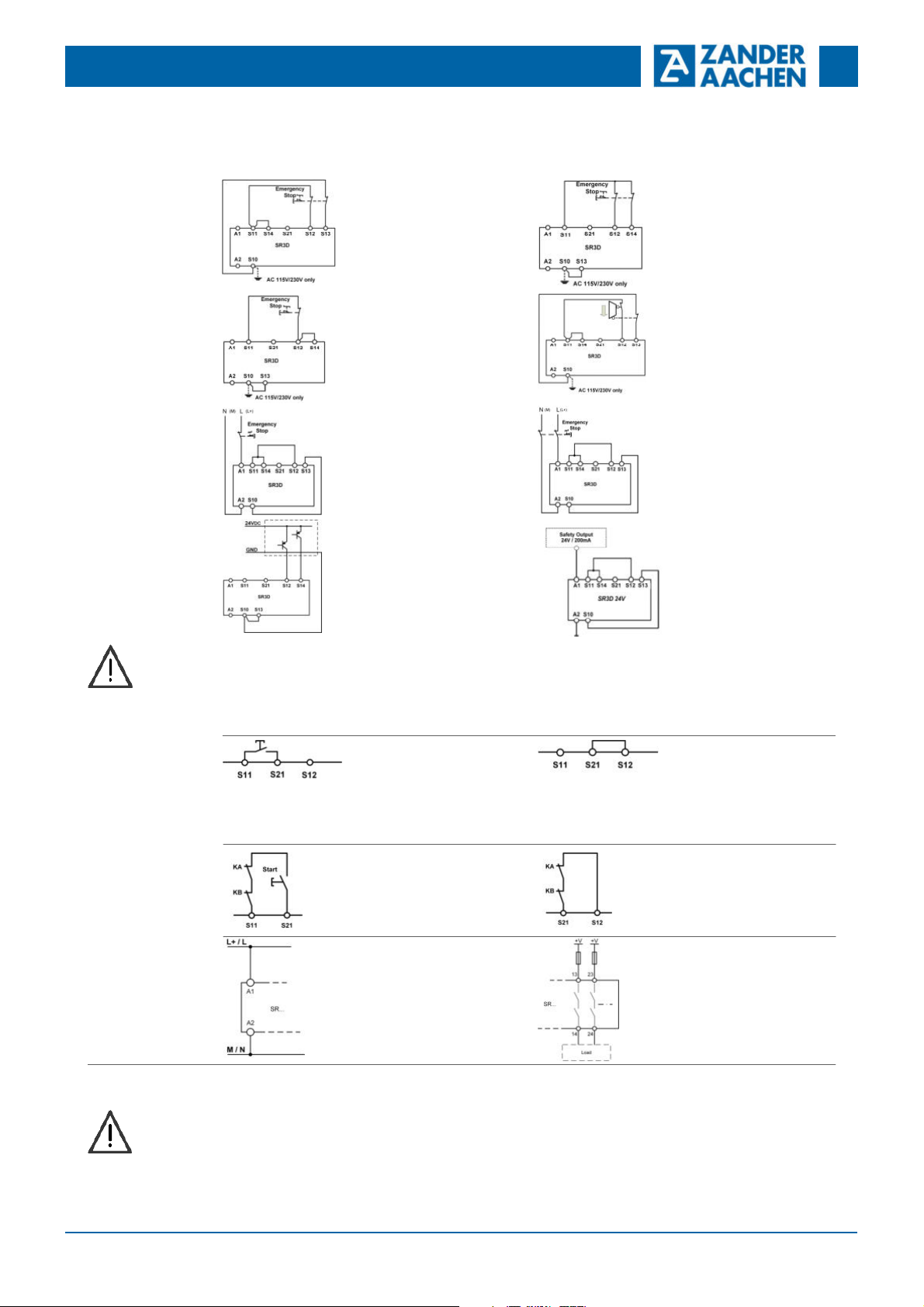
Depending on the application or the result of the risk assessment according to EN ISO 13849-1, the device must be wired as
shown in Fig. 1 to Fig. 14.
Fig. 1:
Dual channel emergency stop
with short circuit and earth fault
detection.
(category 4, up to PL e / SIL 3)
Fig. 3:
Single channel emergency stop
with earth fault detection.
(category 1, up to PL c / SIL 1)
Fig. 5:
Single channel emergency stop
without fault-detection of the
safety switch and the wires.
(category 1, up to PL c / SIL 1)
Fig. 7:
Two channel emergency stop with
pnp-outputs/OSSD-outputs
with its own short circuit monitoring.
(category 4, up to PL e / SIL 3)
Fig. 2:
Dual channel emergency stop
with earth fault detection.
(category 3, up to PL d / SIL 2)
Fig. 4:
Dual channel safety guard
monitoring with short circuit and
earth fault detection.
(category 4, up to PL e / SIL 3)
Fig. 6:
Dual channel emergency stop
without fault-detection of the
safety switch and the wires.
(category 3, up to PL d / SIL 2)
Fig. 8:
Single channel emergency stop
with a safety output. Wired
inside a control cabinet
(minimum degree of protection
IP54)
(category 4, bis PL e / SIL 3;
Condition: Safety output meets
PL e, SIL 3)
English translation
Start Behavior
Feedback Loop
Power supply
and
Safety contacts
Commissioning
Procedure
ATTENTION:
• In order to activate earth fault monitoring, S10 must be connected to PE (protective earth) on the AC 115 V / 230 V devices
• With AC/DC 24 V, connect PE only to the power supply unit according to EN 60204-1
• It must be ensured that any switch-on pulses (light test) sent by the signal generator do not lead to a short activation of the safety relay and
should therefore basically be deactivated
• For applications according to Fig. 7 and Fig. 8 make sure that the ground potential of the signal generator and the SR3D is the same
Fig. 9:
Monitored manual start.
It is monitored that the start button
has been opened before the
safety switch is closed.
(Condition:
power supply may not be interrupted)
Fig. 11:
Feedback loop for monitored
manual start:
The feedback loop monitors
contactors or the expansion
modules .
Fig. 13:
Power supply A1 and A2.
(Power supply according to techn.
Data)
Warning:
Safety contacts will be
activated immediately at
power-on.
Fig. 10:
Automatic start.
Maximum allowable delay when
closing the safety switches at
S12 and S13:
S12 before S13: 300ms
S13 before S12: no limit
Fig. 12:
Feedback loop for automatic
start:
The feedback loop monitors
contactors or the expansion
modules .
Fig. 14:
Connecting load to safety contacts.
(Figure shows example.
Voltage „+V“ according to techn.
Data)
Advice: Follow the guidelines in „Electrical Connection“ during the start-up.
1. Input circuit:
Depending on the risk evaluation choose one of the wiring
diagrams in „Applications“ (Fig. 1 to 8).
2. Choose start mode:
Connect the start button with S11 and S21 for monitored
manual start or connect S21 with S12 directly for automatic
start (Fig. 9 or 10).
Warning:
If “Automatic start” is set, bear in mind that the safety
contacts will switch immediately after the power supply is
connected. If “Monitored manual start” is set, the start button must be opened after wiring.
3. Feedback loop:
If external contactors or extension modules are used,
connect them according to Fig. 11 or Fig. 12.
4. Power supply:
Connect the power supply to A1 and A2 (Fig. 13).
Caution: Power must not yet be activated.
M03
Ver. B
E61-139-00
H. ZANDER
GmbH & Co. KG • Am Gut Wolf 15 • 52070 Aachen • Germany
Tel +49 (0)241 9105010 • Fax +49 (0)241 91050138 • info@zander-aachen.de • www.zander-aachen.de
2

Safety Emergency Stop Relay SR3D
User Information
Check and Maintenance
What to do in
Case of a Fault?
5. Starting the device:
Switch on the operating voltage.
Warning:
If the “Automatic start” starting behavior is set, the safety
contacts will close immediately.
If the “Monitored manual start” starting behavior is set,
LEDs K1 and K2 are lit.
6. Triggering safety function:
Open the emergency stop circuit by actuating the connected safety switch. The safety contacts open immediately.
7. Reactivation:
Switch the device on again as described under 5.
Errors and technical changes reserved
close the start button to close the safety contacts.
The following checks are regularly required to ensure
proper and continuous functioning:
•
Check the switch function
•
Check for signs of manipulation and safety function
bypassing
•
Check if the device is mounted and connected securely
•
Ceck for soiling
Check if the safety device is working properly, in particular:
•
Every time after initial commissioning
•
Every time after replacing a component
•
After every fault in the safety circuit
Regardless of this, the safe functioning of the safety device should be checked at suitable intervals, e.g. as part of the maintenance schedule of the plant. No maintenance is required for the device itself
Device does not switch on:
•
Check the wiring by comparing it to the wiring diagrams.
•
Check the safety switch used for correct function and
adjustment.
•
Check whether the emergency stop circuit is closed.
•
Check whether the start button (manual start) is closed.
•
Check the operating voltage at A1 and A2.
•
Is the feedback loop closed?
Caution: Opening the device is impermissible and will void the warranty.
Device cannot be switched on again after an emergency
stop:
•
Emergency stop circuit was closed again.
•
Was the start button opened before closing of the emergency stop circuit (manual start)?
•
Is the feedback loop closed?
If the fault still exists, perform the steps listed under
“Commissioning Procedure”. If these steps do not remedy
English translation
Techn. Data
In compliance with EN 60204-1; DIN EN ISO 13849-1; EN 62061; EN 50156-1;
EN 746-2; IEC 61508 Parts 1-2 and 4-7; IEC 61511-1
Operating voltage AC 230 V, AC 115 V, AC/DC 24 V
Rated supply frequency 50-60 Hz
Allowable tolerance + / - 10 %
Power consumption DC 24 V AC 230 V
approx. 2 W approx. 6.9 VA
Control voltage at S11 DC 24 V
Control current at S11...S14 max. 100 mA
Safety contacts 3 NO
Auxiliary contacts 1 NC
Switching voltage max. AC 250 V
Contact rating of safety contacts (13-14, 23-24, 33-34) *) AC: 250 V, 2000 VA, 8 A for resistive load
6 switching cycles/ min
250 V, 3 A for AC-15
DC: 30 V, 240 W, 8 A for resistive load
24 V, 3 A for DC-13
UL: C300 / R300
Cumulative current Max. 15 A (13-14, 23-24, 33-34)
Contact rating of auxiliary contact (41-42) AC: 250 V, 500 VA, 2 A for resistive load
DC: 30 V, 60 W, 2 A for resistive load
Minimum voltage/current 5 V, 10 mA
External fuses for safety contacts 10 A gG
6 A gG for applications acc. to EN 50156-1
Wire width 0.14 - 2.5 mm
2
(See Chapter 10.5.5.3.4)
Tightening moment (Min. / Max.) 0.5 Nm / 0.6 Nm
Typ. switch-on delay / switch-off delay < 30 ms / < 20 ms
Length of control lines Max. 1000 m at 0.75 mm2
Contact material AgSnO
2
Service Life mech. approx. 1 x 10⁷
Rated impulse withstand voltage 2.5 kV (control voltage / contacts)
Dielectric strength 4 kV (DIN VDE 0110-1)
Rated insulation voltage 250 V
Protection IP20
Temperature range DC 24 V: -15 °C bis +55 °C
AC 115 V / 230 V: -15 °C bis +55 °C
(see load curve)
Max. altitude ≤ 2000 m (above sea level)
Degree of pollution / Overvoltage category 2 / 3 (DIN VDE 0110-1)
Weight approx. 230 g
Mounting DIN rail according to EN 60715 TH35
*) If several SR3D-24V are mounted closely together the maximum cumulative current is 9A at an ambient temperature of
20°C or 3 A at 30 °C or 1 A at 40 °C. If the current exceeds these limits, keep a minimum space of 5 mm between the
devices.
M03
Ver. B
E61-139-00
H. ZANDER
GmbH & Co. KG • Am Gut Wolf 15 • 52070 Aachen • Germany
Tel +49 (0)241 9105010 • Fax +49 (0)241 91050138 • info@zander-aachen.de • www.zander-aachen.de
3

Safety Emergency Stop Relay SR3D
User Information
Disclaimer and
warranty
Load curve
If the above mentioned conditions for appropriate use are
not complied with or if the safety instructions are not followed or if any maintenance operations are not carried out
as required, this shall lead to an exclusion of liability and
loss of warranty.
ATTENTION!
We would like to point out that it is the full responsibility
of the operator to ensure a plant availability.
Using the SR3D, a safety emergency stop relay according
to
•
EN ISO 13849-1
•
IEC 62061
•
IEC 61508
•
EN 50156-1
•
EN 746-2
•
IEC 61511-1
Errors and technical changes reserved
is used, which will be brought into the safe state when the
safety function is requested.
This means that the connected load is switched off as soon
as a request from connected sensor elements or diagnostic
measures detects a dangerous state, e.g. caused by a
component fault.
Since process-related applications in particular have high
demands on availability, limited availability can also have
significant consquences. It is therefore recommended to
stock a second unit to avoid long downtimes in such a case.
These are recommendations of the manufacturer, the
evaluation of the importance of the plant availability is the
sole responsibility of the operator.
Max. cumulative current depending on the ambient temperature for AC 115 V / 230 V variants with 10 mm space
between the devices.
Cumulative current: ∑ I² = (I
+ I2 + I3)²
1
English translation
Dimension
Drawing
Variants
Fixed
Terminals
Order No. 472270 SR3D, AC 230 V (50-60 Hz), fixed screw terminals
Order No. 472271 SR3D, AC 115 V (50-60 Hz), fixed screw terminals
Order No. 472272 SR3D, AC/DC 24 V (AC: 50-60 Hz), fixed screw terminals
Order No. 474270 SR3D, AC 230 V (50-60 Hz), incl. plug-in screw terminals
Order No. 474271 SR3D, AC 115 V (50-60 Hz), incl. plug-in screw terminals
Order No. 474272 SR3D, AC/DC 24 V (AC: 50-60 Hz), incl. plug-in screw terminals
Order No. 475270 SR3D, AC 230 V (50-60 Hz), incl. push-in twin spring connector
Order No. 475271 SR3D, AC 115 V (50-60 Hz), incl. push-in twin spring connector
Order No. 475272 SR3D, AC/DC 24 V (AC: 50-60 Hz), incl. push-in twin spring connector
Order No. 472592 EKLS4, set of plug-in screw terminals
Order No. 472595 EKLZ4, set of push-in twin spring connector
Order No. 472596 Spacer for a defined minimum distance between two safety relays (see derating)
Plug-In
Terminals
H. ZANDER
GmbH & Co. KG • Am Gut Wolf 15 • 52070 Aachen • Germany
Tel +49 (0)241 9105010 • Fax +49 (0)241 91050138 • info@zander-aachen.de • www.zander-aachen.de
M03
Ver. B
E61-139-00
4

Safety Emergency Stop Relay SR3D
User Information
Safety
Charcteristics
Errors and technical changes reserved
Safety characteristics according to EN ISO 13849-1
Load - AC-15 / DC-13 ≤ 1 A / ≤ 1 A ≤ 2A / ≤ 2A ≤ 3A / ≤ 3A
Max. duration of use [Years]
20 20 20
Category 4 4 4
PL e e e
PFHd [1/h] 1.2E-08 1.2E-08 1.2E-08
nop [Cycles / year] - AC-15 / DC-13 ≤ 50,000 / ≤ 350,000 ≤ 35,000 / ≤ 100,000 ≤ 8,760 / ≤ 8,760
Safety characteristics according to IEC 61508 - High Demand
Conditions: Days of operation/year: 365; Hours/Day: 24; Switching-Cycle/Hour: 1; Maximum load AC-15 / DC-13
Max. duration of use [Years] 20
Proof-Test-Intervall [Years] 20
PFH 6.2E-11
SIL 3
Safety characteristics for alternate 1oo1 structure for process industry - High Demand
Conditions: Days of operation/year: 365; Hours/Day: 24; Switching-Cycle/Hour: 1; Maximum load AC-15 / DC-13
Device type A
HFT 0
SIL 3
SFF [%] 99,96
[FIT]
λ
SD
[FIT]
λ
SU
[FIT]
λ
DD
[FIT]
λ
DU
PFH [1/h] 6,2E-11
0
109,41
6,2
0,06
Safety characteristics according to IEC 61508 - Low Demand
Conditions: Maximum load AC-15 / DC-13
Max. duration of use [Years] 20
Proof-Test-Intervall [Years] 9
PFD
9.87E-05
AVG
SIL 3
Safety characteristics for alternate 1oo1 structure for process industry - Low Demand
Conditions: Maximum load AC-15 / DC-13
Device type A
HFT 0
SIL 3
SFF [%] 97,53
[FIT]
λ
SD
[FIT]
λ
SU
[FIT]
λ
DD
[FIT]
λ
DU
PFD
(e.g. for T = 1 year) 1,37E-05
avg
0
123,44
0
3,12
English translation
Proof-Test
In order to check the proper function of the device, the following steps have to be carried out
•
Demand the safety function by opening the safety circuit. Check that the relay contact (13-14; 23-24; 33-34) opened by
activation of the safety function.
•
Close the safety circuit and start the device again. Check that the safety contacts (13-14; 23-24; 33-34) closed again.
If the device doesn‘t switch on again, the proof-test failed.
ATTENTION:
If the proof-test fails, the device must be replaced. Otherwise there is a risk of loss of functional safety.
H. ZANDER
GmbH & Co. KG • Am Gut Wolf 15 • 52070 Aachen • Germany
Tel +49 (0)241 9105010 • Fax +49 (0)241 91050138 • info@zander-aachen.de • www.zander-aachen.de
M03
Ver. B
E61-139-00
5
 Loading...