

ZANDER HDK 400/100, HDK 80/100, HDK 600/100, HDK 50/250, HDK 80/250 Operating Instructions Manual
...
High Pressure Dryer
HDK
50/100-600/350
Operating Instructions
Issue 05-2005/EN

Declaration of Conformity
ZANDER Aufbereitungstechnik GmbH & CO KG
Im Teelbruch 118
D – 45219 Essen Kettw ig
hereby declares with sole responsibility, that the products
high pressure dryer
series HDK 18/25 to 600/420
assembly type: assembly acc. to Art. 3 No. 2.2,
which this declaration refers to, conform to Directive 97/23/EC and were
subjected to a conformity assessment according to Annex III Modules B + D (for
assembly assessment).
For the assembly, the EC type approval certificate SIG 0272175/1 by Lloyd’s
Register Quality Assurance GmbH, Hamburg, is available.
The quality assurance system is monitored by the service provider stated below
Lloyd’s Register Quality Assurance GmbH (identification number 0525)
Mönckebergstraße 27, D - 20095 Hamburg.
The assembly consists of pressure appliances according to the classification list
(attached to the technical documentation provided by the manufacturer).
The following standards / technical specifications were used:
harmonized standards: DIN EN 292-1, DIN EN 292-2, DIN EN 1050,
DIN EN 50081, DIN EN 50082, DIN EN 60204
The following other EC directives were used:
98/37/EC
89/336/EEC
73/23/EEC
Signature
Dr. Walter Steudle
Managing Director


Machine passport
Type designation HDK
Order no.
Project no.
Build no.
Vessel no.
Vessel no.
Year of manufacture 2005
Issue date of these operating instructions 2005-05 EN
It is the responsibility of the owner,
to enter for the first time any appliance data not stated above,
to keep these appliance data up to date.
The above-stated appliance data provide for a clear identification of the dryer and
its components, and significantly facilitate any service measures.
Further important data on the dryer such as the details on the permissible
operating pressure and the electrical connection are found on the type plate (for
position of the type plate see page 12).


Table of contents
General information................................................................................................9
Manufacturer's details................................................................................................................. 9
Details on the dryer................................................................................................................... 10
About these operating instructions........................................................................................... 11
For your own safety..............................................................................................12
Signs, instruction plates and danger zones at the dryer.......................................................... 12
Intended use of the dryer.......................................................................................................... 14
General safety notes................................................................................................................. 14
Safety notes on specific operating phases............................................................................... 15
Technical product description ............................................................................18
Summary drawing..................................................................................................................... 18
Function description.................................................................................................................. 19
Available options....................................................................................................................... 20
Transportation, installation and storage ...........................................................23
Information on transportation packaging.................................................................................. 23
What to do in the case of transport damage occurring?.......................................................... 23
Transporting and installing the dryer........................................................................................ 24
Installing and anchoring............................................................................................................ 25
Storing the dryer ....................................................................................................................... 26
Installation..............................................................................................................28
Preconditions for installation..................................................................................................... 28
Connect piping .......................................................................................................................... 28
Installing the electrical connection............................................................................................29
Start-up ...................................................................................................................32
Requirements for initial start-up ...............................................................................................32
Setting times of the operating phases...................................................................................... 33
Overview of operating and control elements............................................................................ 33
Emergency shutdown............................................................................................................... 36
Start up dryer ............................................................................................................................ 36
Changing cycle mode (optional)............................................................................................... 39
Monitoring dryer operation..................................................................................41
With dewpoint-sensing control (optional) ................................................................................. 41
Shutdown and restart dryer.................................................................................42
Mains power failure................................................................................................................... 42
HDK350_EN_01_2005-05-10

Emergency shutdown............................................................................................................... 43
Depressurising and shutting down the dryer............................................................................ 43
If work is to be carried out on the electrical system................................................................. 43
Restart ...................................................................................................................................... 44
Maintenance and repair of the dryer.................................................................. 45
Notes on maintenance.............................................................................................................. 45
Regular maintenance intervals................................................................................................. 46
Daily maintenance tasks........................................................................................................... 47
Weekly maintenance tasks....................................................................................................... 48
Maintenance work to be completed every 12 months ............................................................. 48
Maintenance work to be completed every 48 months ............................................................. 52
Identify and eliminate faults ............................................................................... 56
Summary of faults..................................................................................................................... 56
Index....................................................................................................................... 59
Annex with technical documentation................................................................ 62
Technical data .......................................................................................................................... 63
Replacement and wear parts list.............................................................................................. 65
Logic control diagram ............................................................................................................... 68
Flow diagram ............................................................................................................................ 70
Dimensional drawing ................................................................................................................ 71
HDK350_EN_01_2005-05-10

General information
Manufacturer's details
Name and address
Zander Aufbereitungstechnik GmbH & Co. KG
Im Teelbruch 118 Postfach 185524
45219 Essen 45205 Essen
Telephone ++49 (0)2054/934-0
Telefax ++49 (0)2054/934-164
Internet: www.zander.de
E-mail: info@zander.de
General information
Service and orders
Service and spare part order
Telephone ++49 (0)2054/934-180
Telefax ++49 (0)2054/934-117
You can also use these telephone numbers to order consumables such as
desiccant etc. as well as spare parts. When ordering spare parts, always state
the type and build no. of the dryer. Both are shown on the type plate of the
dryer.
HDK350_EN_01_2005-05-10 9

Details on the dryer
Details on the dryer
Standard equipment
Dryer, comprising
2 vessels, filled with desiccant
1 upstream filter
1 downstream filter
Piping and muffler
Control system
Associated documents
Operating instructions (present)
Technical documentation (see annex)
Circuit diagrams (see separate document)
Warranty notes
In the following cases, the warranty shall be void:
If aggressive media in the compressed air and in the environment cause
corrosion damage and functional faults on the dryer.
If the dryer is used without prior approval and confirmation in writi ng by the
manufacturer for purposes other than those specified in these operating
instructions or contractually agreed.
If preset parameters (e. g. on the control system etc.) are changed without
prior approval and confirmation in writing by the manufacturer.
If the dryer is transported or stored incorrectly.
If the dryer is sited and installed incorrectly.
If the dryer is repaired or maintained incorrectly.
If the dryer is operated by perso nnel that does not have the requisite
qualifications.
If modifications are carried o ut on the dryer, the manufacturer did not
approve that.
In the event of non-compliance the manufacturer will not accept any liability for
any consequential damage whatsoever.
10 HDK350_EN_01_2005-05-10

About these operating instructions
These operating instructions contain basic information on the safe useof the
dryer.
Characters and symbols used
► Work steps that you have to carry out in the sequence stated are marked by
black triangles.
Lists are marked by a small box.
Note:
These notes provide you with hints and information on the safe and
efficient handling of machines and devices.
Warning!
These safety notes w arn against damage to property and help you to avoid
such damage.
General information
Danger!
These danger notes w ith a grey background warn against personal injury
and/or danger to life and limb; danger notes help you to avoid serious or
life-threatening situations for yourself and/or third parties.
Target group of these operating instructions
These operating instructions are intended for all persons working on and using
the dryer. We assume that all such persons are specialist personnel, e.g. fitters
or electricians.
Operating instructions: handling
These operating instructions must be continuously available at the site where the
dryer is used. We recommend to prepare a copy and to keep the same i n a safe
and freely accessible place next to the dryer. Keep the original document in a
safe place.
HDK350_EN_01_2005-05-10 11

Signs, instruction plates and danger zones at the dryer
For your own safety
The dryer has been built in accordance with the state of the art and the
recognized technical safety regulations. Nevertheless, there is a risk of personal
injury and damage to property when the dryer is used, if
it is operated by non-qualified personnel,
not used within its intended design specifications,
is repaired or maintained incorrectly.
Note:
For your own safety and to prevent machine damage, please note the
information and safety notes in these operating instructions when
working with the dryer.
Signs, instruction plates and danger zones at the dryer
Signs and instructions
Vessel plate
Type plate of the dryer
Type plate of the filter
Front view
Please note the above plates and instructions attached to the dryer. Ensure that
they are not removed and are always readable.
12 HDK350_EN_01_2005-05-10

Hazard areas on the dryer
For your own safety
Hazard caused by electrical voltage
Hazard caused by overpressure
Hazard caused by sudden air ejection during
expansion
Hazard area
Warning against hazardous electrical voltage
Different parts of the dryer carry electrical current. These parts may be
connected, opened, and maintained by authorized specialist personnel only.
Warning against overpressure
The entire dryer is under pressure. Before commencing any work, the plant
must be depressurised.
Warning against sudden air ejection
When the vessels are depressurised, air flows suddenly out of the sound
absorber:
This causes a sudden loud cracking noise.
Due to particles carried in the air flow, there is a very considerable risk of
eye injury.
When working on the dryer, always wear eye and ear protection equipment.
Skid risk
When emptying and filling the vessels with drying agent, there is a risk of
skidding caused by spilt drying agent.
Symbol in
operating
instructions
HDK350_EN_01_2005-05-10 13

Intended use of the dryer
Intended use of the dryer
The dryer is exclusively intended for drying compressed air. Depending on
defined input conditions, it dries compressed air for industrial use.
The dryer is designed for compressed air, which is free from aggressive water,
oil, and solid matter constituents.
As standard, the dryer is intended to be sited within a building and protected
against the weather. When it is sited in the open air (option), the i nstructio ns on
page 20 must be complied with.
The dryer may be operated only in accordance with the data on the type plate
and in accordance with the contractual conditio ns.
Suspected misuse
The dryer must not be misused as a climbing aid! Pipes, valves, and similar
fittings have not been designed for such loads. They could fracture, tear off, or
become damaged in another way.
General safety notes
For your ow n safety, when carrying out any work on the dryer comply w ith
all applicable national safety regulations!
Personnel qualification
Only authorized and qualified specialist perso nnel may be tasked with the work
on the dryer described in these operating instructions.
Conversions and modifications
Without prior approval by the manufacturer, no conversions and modifications
must be made to the dryer! Any non-approved modifications may restrict the
operational safety of the dryer and cause damage to property or perso nal injury.
Handling drying agents
The drying agents used do not pose any risk to health. However, when filling and
emptying the vessels with drying agents, increased dust generation may occur.
Please comply with the following i nstructions:
When filling drying agents into the vessels, wear a dust mask and eye
protection!
If a spillage occurs, any spilt drying agent must be taken up immediately.
There is a risk of skidding!
14 HDK350_EN_01_2005-05-10

Safety notes on specific operating phases
Transportation and siting
Only use suitable and technically perfect lifting gear with a sufficient carrying
capacity.
Carefully secure the dryer during transportation.
Start-up
Warning against sudden air ejection!
During expansion the pressure is released suddenly through the muffler:
A loud cracking noise occurs which can injure your hearing.
Particles carried in the air can injure your eyes or skin.
Always wear eye and ear protection, therefore, when you are in the vicinity
of the dryer!
For your own safety
Hazard due to a sudden release of pressure!
Never remove any parts of the dryer, or manipulate the same in any way,
for as long as the plant is still pressurised! A sudden escape of pressure
may cause serious injuries.
Before carrying out any work on the dryer, first depressurise the plant.
Carry out all prescribed tests and checks.
The factory settings on the control board in the switchbox must not be
changed on any account without prior approval by the manufacturer.
Before start-up, ensure that no tools or other foreign parts have been left
lying in a part of the dryer where they mi ght pose a hazard to the dryer being
started up.
Emergency shutdown
In any emergency, proceed as described in the section Depressurising and
shutting down the dryer on page 43.
Monitor operation
Warning against sudden air ejection!
During expansion the pressure is released suddenly through the muffler:
A loud cracking noise occurs which can injure your hearing.
Particles carried in the air flow act like bullets and can injure your
eyes or skin.
Always wear eye and ear protection, therefore, when you are in the vicinity
of the dryer!
HDK350_EN_01_2005-05-10 15

Safety notes on specific operating phases
Only operate the dryer within the permissible limits (see type plate). By
operating the dryer in conditions that go beyond the defined values, the dryer
is subjected to loads for which it has not been designed. This may cause
functional defects.
Loud noise generation!
During expansion the pressure is released suddenly through the
expansion valve. A loud cracking noise may occur.
Always wear ear protection, therefore, w hen you are next to the dryer
during operation.
The more po werful the dryer is, the more noise may be generated during
operation. Temporarily, the actual noise emission may even exceed
95 dB(A). T herefore, the operator must provide suitable protective equipment
(e. g. ear protection).
Check the dryer regularly for externally visible damage and defects. Any
changes, even in its operating behavio ur, must be reported immediately to
the competent office or person.
In the event of an emergency or if a safety-relevant disruption occurs (e.g.
escaping compressed air, defective component), the dryer must be shut
down immediately as described in the sectio n Depressurising and shutting
down the dryer on page 43). The unit may only be restarted after all defects
have been eliminated.
Maintenance of the dryer and fault removal
Hazard due to a sudden release of pressure!
Never remove any parts of the dryer, or manipulate the same in any way,
for as long as the plant is still pressurised! A sudden escape of pressure
may cause serious injuries.
Before carrying out any work on the dryer, first depressurise the plant.
Carry out maintenance work only when the plant has been shut down and
depressurised!
The factory settings on the control board in the switchbox must not be
changed on any account without prior approval by the manufacturer.
Bolt connections must be undone with care! Note ram pressure values!
Otherwise emerging media may cause perso nal injury.
Never carry out any welding on a vessel or change the same i n any other
way!
Never use pipes and fittings as steps or holding points! The components
might fracture, or the distortions which occur may cause internal damage on
the dryer. There is a risk of injury by slipping off the components,
components breaking off, and expanding compressed air!
Never leave tools, loose parts or cloths in, at or on the dryer.
Following maintenance work always test all flange and bolt connectio ns for
leak tightness and secure seating.
16 HDK350_EN_01_2005-05-10

Only use replacement parts that are suitable for the relevant function and
meet the technical requirements stipulated by the manufacturer. This is
always the case, if you use original replacement parts only.
Disassembly and disposal
Hazard due to a sudden release of pressure!
Never remove any parts of the dryer, or manipulate the same in any way,
for as long as the plant is still pressurised! A sudden escape of pressure
may cause serious injuries.
Before carrying out any work on the dryer, first depressurise the plant.
Dispose all parts of the dryer, the drying agent, and all other operati ng
materials in an environmentally safe way and in accordance with all current
statutory regulations. The waste code numbers of the drying agents can be
obtained from the manufacturer (for the manufacturer's address see page 9).
For your own safety
HDK350_EN_01_2005-05-10 17

Summary drawing
r
y
r
r
s
Technical product description
Summary drawing
Front view
Vessel pressure
gauge
Manomete
On/Off-Switch
Power suppl
connecto
Compressed air outlet Compressed air inlet
Downstream filte
Valve
Pressure reducer with
manometer
Control cabinet
Differential pressure
gauge
Upstream filter
Hand drain
Muffler
18 HDK350_EN_01_2005-05-10

Function description
The dryer dries the compressed air supplied by the compressor and makes it
available for industrial use.
Upstream filters clean the compressed air and remove dust, dirt, oil, and water
droplets, before the compressed air reaches the dryer. Thus, an upstream filter is
also used for extending the service life of the drying agent.
Downstream filters clean the compressed air from drying agent abrasions, before
it is fed into the compressed air system.
The two vessels contain an extremely porous drying agent by means of which
humidity is removed from the compressed air and stored just as in a sponge. The
stored humidity is then removed again from the drying agent and re-introduced
into the ambient environment.
To this end, the two vessels alternate between different operating modes. Whilst
in one vessel, compressed air is de-humidified (adsorption), in the other vessel
the humid drying agent is prepared for another charge (regeneration). These two
states, which run in parallel during compressed air preparation, are described
below.
Technical product description
Adsorption
Via a compressor, humid compressed air is supplied to the upstream filter. From
here, the compressed air flo ws upwards through the absorption vessel, which is
pressurised. In so doing, the drying agent dehumidifies the air. The dry
compressed air is supplied to the pipe network via the downstream filter.
Regeneration (running in parallel to the adsorption)
At the same time the other vess el is prepared for a renewed take-up of humidity.
This process is called regeneration.
The regeneration is subdivided into three phases: expansion, dehumidification,
and pressure build-up.
With the dewpoint-sensing control option, the regeneration phase is followed by a
standby phase.
Expansion phase
During the expansion phase the pressure in the right vessel is released via the
muffler down to ambient pressure within just a few seconds. The outflow of the
compressed air becomes noticeable due to a sudden powerful flow noise at the
muffler.
Dehumidification phase
Prior to being released into the pipe network, dried compressed air is bled by
means of an orifice plate. This separate regeneration air flow is fed through the
depressurised vessel. The humidity stored in the drying agent is taken up by the
air flow and expelled into atmosphere via the muffler.
HDK350_EN_01_2005-05-10 19

Available options
Switchover
Pressure build-up phase
After dehumidification the pressure in the regenerated hollow section vessel is
built up to operating pressure, so that the switchover from regeneration to
adsorption can take place at operating pressure level.
Standby phase (only with the dewpoint-sensing control option)
When in standby phase, the fully regenerated vessel is ready for absorption
operation. The system is switched to this vessel, as soon as the measured
dewpoint at the compressed air outlet has reached the set dewpoint value for
switchover.
When the drying agent in the adsorbing vessel has taken up a sufficient level of
humidity, then the switchover between the vessels will be effected between the
vessels. Following switchover, the above-described process is repeated, with the
adsorption and regeneration now taking place in the respective different vessel.
Available options
The following options are available for the dryer:
Start-up device
Outside installation
Auxiliary heater
Signalling contacts of control system
Regeneration gas return line for compressor synchronisation
Dewpoint-sensing control
Pneumatic control
Paint compatible design
Start-up device
A start-up device basically consists of a pressure holding device, which is located
at the rear of the dryer. The pressure holding device ensures that pressure can
build up in the dryer and adsorption take place.
It is always required when an empty compressed air reservoir or an empty
compressed air system must be filled downstream of the dryer (e.g. following
weekend shutdowns and when the pressure in the compressed air system can
frequently drop below the stated operating pressure).
The start-up device cannot be combined with the regeneration gas return line
option.
Outside installation
As standard, the dryer is not suitable for outside installation, as its functio n and
service life is influenced by the following factors:
Environmental humidity due to rain (or other deposit)
Corrosion caused by environmental humidity or a salt-containing environment
20 HDK350_EN_01_2005-05-10

Freezing of valves, cocks, flaps, and other components at low temperatures
Therefore, a planned o utside installation must always be discussed in advance
with the manufacturer to allow specific technical design measures to be provided
for the installation location.
Auxiliary heater
For installation sites with temperatures under +1 ºC (33,8 ° F), the wet side of the
dryer must be equipped with an auxiliary heater to prevent valves, cocks, flaps,
and other components from freezing up.
Signalling contacts of the control system
The control system is equipped with a digital input for the synchronised operation
with a compressor. This feature allows for synchronised and thus efficient dryer
operation with disco ntinuous compressor operation.
The control system can also be equipped with an optional operation signalling
contact with which the dryer operation can be monitored from an external device.
Dryers with the optional dewpoint-sensing control are equipped with such a
contact as standard. It is used for the transmission of operating signals and for
the output of dewpoint alarms.
Technical product description
Regeneration gas return for compressor synchronisation
Compressor synchronisation helps reduce energy costs, as the dryer can be
operated independently of the compressor.
When the compressor is switched off, the regeneration gas return ensures that
regeneration is continued, as soon as a certain compressed air volume is
reached behind the dryer.
The regeneration gas return must be adjusted to suit the installed compressed air
system. Prior to installation, please consult the manufacturer.
The regeneration gas return option cannot be combined with the optional start-up
device.
Dewpoint-sensing control
With a dewpoint-sensing control system, you can operate the dryer in fixed or
variable cycles. In the fixed cycle, switchover is effected after a fixed time period
(usually after 5 minutes). In the variable cycle, the switchover is effected in
relation to the dew point reached and the charging of the drying agent . T he
adsorption time in the variable cycle amounts to 60 minutes maximum.
Pneumatic control
A pneumatic control system can be used wherever an alternative to the electronic
control system is required, such as e.g. in explosion hazard areas.
HDK350_EN_01_2005-05-10 21

Available options
Paint compatible design
Paint shop plants impose particularly stringent requirements with regard to the
cleanliness of the compressed air, as already the minutest contaminations can
reduce the quality of the paint finish. Even minute quantities of oil and grease
containing foreign materials or solvents — above all silicones — are sufficient to
cause pits, discolorations, swelli ngs, and other contami natio ns i n t he pai nt finis h.
Dryers in a paint compatible design comprise seals and filters that are absolutely
free of grease and silicon and thus ensure a high quality of the compressed air
used for painting.
22 HDK350_EN_01_2005-05-10

Transportation, installation and storage
Transportation, installation and storage
Danger due to incorrect transportation!
The dryer must be transported by authorized and qualified specialist
personnel only. During transportation all applicable national regulations
for accident prevention must be complied w ith. Otherwise there is a risk of
personal injury.
Only use suitable and technically perfect lifting gear with a sufficient carrying
capacity.
During transportation the dryer must be carefully secured against falling over.
The manufacturer will not be liable for any damage caused by incorrect storage
or incorrect transportation. Please note therefore the following instructions as well
as the storage instructio ns on page 26.
Information on transportation packaging
Depending on the type of transportation, the dryer is delivered in different types
of packaging:
All transportation types: the apertures of the dryer are closed off by means of
plugs.
In additio n, when transportation is effected by air: the dryer is packaged in a
wooden box.
In additio n, when transportation is effected by ship: the dryer is packaged in a
film material and in a wooden box.
If the packaging is undamaged
► The undamaged packaging should be removed only at the final installation
site, as it offers protection against any weather influences.
What to do in the case of transport damage occurring?
► Check whether only the packaging or the dryer itself were damaged.
► If any damage is found, please contact the manufacturer immediately to file a
damage report. The telephone number is found on page 9.
Warning!
A damaged dryer must not be taken into operation! Damaged components
may lead to functional faults and possibly cause further damage.
HDK350_EN_01_2005-05-10 23

Transporting and installing the dryer
Transporting and installing the dryer
Requirements for the installation site
The conditions at the installation site have a large influence on the functional
capability of the dryer and the service life of the drying agent. In order to ensure a
mode of operation, which is as co ntinuous as possible, and low maintenance, the
installation site must meet the following requirements:
The installation site must be located within a building - protected against
humidity. For outside installation (option) the instructions on page 20 must be
complied with.
The ambient temperature must not drop below +1 °C (33,8 °F). If necessary,
an auxiliary heater is to be provided (for information on the auxiliary heater,
see page 21).
When selecting the installation site, it should be taken into account that the
noise emission of the dryer can exceed 95 dB(A) temporarily (for further
information on the noise emission, see also page 16).
The installation area must be level, firm and free of vibrations. It must have
the necessary carrying capacity for the weight of the dryer. The weight of the
dryer is specified in the technical data section of the annex.
The dryer should be installed with
sufficient spacing at the top, sides, and
rear, in order to be able to carry out
maintenance work and change the
dryi ng age nt witho ut any hi ndra nces
(see figure).
If in doubt, the installation site must be inspected by specialists. If you have any
queries in this regard, please contact the manufacturer (for details see page 9).
Transportation using lifting or forklift trucks
Warning against damage to property!
The dryer is delivered on a transportation pallet.
Necessary spacing at the top and sides
= min. 1 m
Therefore, always transport the dryer on a lifting or forklift truck.
24 HDK350_EN_01_2005-05-10

► Secure the dryer on the lifting
or forklift truck against sliding
movements.
► Transport the dryer to its
installation site.
Transportation, installation and storage
Dryer on transportation pallet
Installing and anchoring
Installing
► Remove the packaging of the dryer.
► Attach suitable lifting gear to the stand profiles and cross beams.
Risk of tilting!
The dryer should only be transported in an upright position. However, this
means that the centre of gravity of the unit is located in the upper half of
the dryer, so that there is a serious risk that the unit might topple over.
When attaching the dryer to the lifting gear, observe its centre of gravity!
► Position the dryer at its installation site.
HDK350_EN_01_2005-05-10 25

Storing the dryer
Anchoring the dryer
The upright stand profiles of the dryer are provided with pre-drilled anchorage
bores.
► Use suitable attachment material to anchor
the dryer to the floor (see figure).
► In the case of vibrating floors: place the dryer
on suitable vibratio n dampers.
Bores at the foot of the dryer
Storing the dryer
If the dryer is to be stored for an extended period of time, the storage location
must me et t he follo wi ng co nditions:
The dryer must not be stored in the open air.
The storage room must be dry.
The storage room must be free from dust or the dryer must be covered by a
protective sheet.
The storage room must have an ambient temperature of at least +1 °C
(33,8 °F).
In order to store the dryer proceed as follows:
► Take dryer o ut of operation as described on page 43.
► Ensure that the compressed air inlet valve installed by the owner, and the
installed compressed air outlet valve installed by the owner, are both closed,
and that the dryer is depressurised.
► Disconnect dryer from the compressed air system.
► Disconnect the dryer from the electrical power supply and all external lines.
► Use film material or similar to close the compressed air inlet apertures and
compressed air outlet apertures on the dryer in order to protect them against
contamination.
► If possible cover dryer with a protective sheet.
The dryer can now be stored for long periods.
26 HDK350_EN_01_2005-05-10

Note:
If you w ish to take the dryer back into service after an extended period
of storage, please proceed as described for its first commissioning
and start-up (see page 37).
Store drying agents
► Do not store drying agents in the open air.
► Protect drying agents against humidity.
Transportation, installation and storage
HDK350_EN_01_2005-05-10 27

Preconditions for installation
Installation
Only authorized and qualified specialist personnel may carry out work on
pipes and electrical systems.
As soon as the dryer has been set up at its installation location, you can install
the compressed air infeed and outlet lines make the electrical connections.
Preconditions for installation
For a correct installation the following preco nditions must be met on the part of
the owner.
Connections and lines for the infeed and outfeed of compressed air must be
provided.
A compressed air inlet valve as well as a compressed air outlet valve must
be installed by the owner, so that the dryer can be installed and maintained in
a depressurised condition (see also the installation example on page 29).
All pipes, co uplings, and connections must have the correct diameter and
match the operating pressure.
Hazard caused by exceeding the limit values!
A safety device must be prov ided in order to protect against the maximum
permissible operating pressure from being exceeded.
The data required to meet these preconditions are contained in the technical
documentation attached in the annex.
Warning!
If the above preconditions are not complied with, a safe operation of the
dryer cannot be assured. Also, the functionality of the dryer may be
detrimentally affected.
Connect piping
In order to ensure that the dryer operates optimally, the dryer must be assembled
into the compressed air system free of all stresses.
► Ensure before connection that all infeed and outfeed compressed air lines
and valves are clean and undamaged.
► Check the bolt connections and retighten if necessary, as they co uld have
worked loose during transportation.
► Remove plugs on the pressure inlet and outlet.
28 HDK350_EN_01_2005-05-10

Installation
All piping must be free from any stress and tension whatever!
Pipes subject to stress may burst due to the load placed on them during
operation. T his may cause damage to property and personal injury.
► Use steel pipes to connect the dryer to the compressed air system.
The following figure shows an installation example.
Compressed air system Item Component
1 Entry, humid air
2 Compressed air inlet
valve, owner end
3 Upstream filter
4Dryer
5 Downstream filter
6 Compressed air outlet
valve, owner end
Example of an installation
► The connection lines for the upstream filter (3) are to be installed at a slight
incline in the direction of the upstream filter.
► One shutdown valve each (2, 6) is to be installed at the compressed air inlet
and outlet ends of the dryer.
Installing the electrical connection
Warning against electrical voltage
Only qualified specialist personnel may carry out w ork on the electrical
system!
7 Outlet, dry air
Installing the supply cable
The components of the dryer have been connected to the control cabinet at the
factory. You only need to connect the control cabinet to the electrical supply
cable.
The switchbox is provided with a connector where electrical power must be
connected.
HDK350_EN_01_2005-05-10 29

Installing the electrical connection
► Ensure that the cross-section of the electrical supply cable corresponds to
the power rating of the dryer and the electrical voltage provided by the
customer.
► Make the electrical supply cable to the dryer voltage-free.
► Secure the electrical supply cable to the dryer against switch-on.
► Undo bolt (1) on the connector and
withdraw connector with seal from the
switchbox.
► Use a suitable tool to remove the
terminal bloc k from the connection
box.
► Undo the PG union and pull the cable
through the aperture (3). The
exposed phase ends should not be
longer than 35 mm max.
► Now make the cable connectio n as
follows:
— Earth
— L1 to terminal 1
— N to terminal 2
to terminal PE
Terminal 3 is not used.
► Fit terminal block into the connector and use bolt to remount the connector
with seal on the switchbox.
► In all phases the dryer must be protected against short circuits by means of
fuses.
► In order to relief cable strain, re-tighten the PG union.
Connecting the external signalling lines
For compressor synchronisation
The control system is equipped with a digital input that ensures that the dryer can
only be operated while the compressor is on.
If the compressor is switched off, the regeneratio n process started in one of the
chambers is however completed. Subsequently, the respective expansion valve
is automatically closed. In standby mode, the control system remains switched
on, and the economy cycle LED is on. The dryer is now ready for the next
switching procedure, which takes place as soon as the compressor is switched
on again.
Connect electrical cable to device
adapter
To install the external line, proceed as follows:
► Connect the signalling line to the potential-free busbar connection of the
compressor to terminals 1 and 2 on the control board (s ee circuit diagram).
30 HDK350_EN_01_2005-05-10

For operation monitoring system (optional)
Operators have the option to connect the dryer to a fault signalling system,
connecting the respective line to a potential-free operation signalling contact.
With this option, the following statuses and events can for example be
transmitted to a remote control room:
Dryer on (contact made)
Power supply disconnected (no contact)
Dewpoint alarm (only with dewpoint-sensing control option, no contact)
To install the external lines, proceed as follows:
► Connect the lines of the fault signalling system to relay K5 (see circuit
diagram).
Check bolt connections
Before the initial start-up:
► Check all unions and bolt connections as well as the terminals in the control
cabinet for secure seating; re-tighten if necessary.
Installation
HDK350_EN_01_2005-05-10 31

Requirements for initial start-up
Start-up
Warning!
The dryer must be taken into operation by trained personnel only!
Untrained personnel does not have the required know ledge. Such
personnel might cause serious faults.
Note:
You can order the initial commissioning and start-up from the
manufacturer and have your personnel trained by the manufacturer.
For telephone number, see page 9.
Carry out all prescribed tests and checks.
Before start-up, ensure that no tools or other foreign parts have been left
lying in a part of the dryer where they mi ght pose a hazard to the dryer being
started up.
Requirements for initial start-up
For the first start-up the following preconditions must have been met:
The pipe system is free from
— scales
— thread abrasions
— welding beads and
— o ther co ntami nati ons.
All shutdown valves of the compressed air inlet and outlet valves installed by
the owner are closed.
The dryer is correctly sited and installed.
Checks before start-up
Ensure that
all pipe, cable and bolt connections on the dryer have been retightened,
no pipes chafe against body edges,
all mountings are perfectly secure,
the electrical connections are in safe contact and in good condition,
owner-end and pressurised parts such as safety valves or other devices are
not blocked up by dirt or paint,
all compressed air system parts which are pressurised (valves, hoses etc.)
are free from wear symptoms and defects.
32 HDK350_EN_01_2005-05-10

Setting times of the operating phases
In its standard version the dryer is delivered with a time-dependent co ntrol
system. The phase sequence occurs in a fixed cycle.
With the optional dewpoint-sensing control, the dryer can also be operated at
variable cycles (depending on the dewpoint).
The following table provides information on the duration of the individual phases.
Phase duration Fixed cycle Variable cycle
Adsorption 10 min 60 min, ma xi mu m
Regeneration, total 10 min 10 min
− of which: expansion time
− of which: dehumidification time
− of which: pressure build-up
Standby — ~ 50 mi n, ma xi mu m
Start-up
~ 0.2 min ~ 0.2 min
~ 8 min ~ 8 min
~ 2 min ~ 2 min
Overview of operating and control elements
ON/OFF switch
The ON/OFF switch (2) is located to the side of the control cabinet and above the
mains plug (1, see figure):
If it is set to 0, the power supply is disconnected and the dryer is switched off.
The main and expansion valves are normally closed. This ensures that the
main flow direction is blocked when the dryer is switched off.
If the switch is set to I, the dryer is switched
on and begins to operate in fixed cycle mode
(i.e. time-controlled).
If the switch is set to position II, the dryer is
switched on and begins to operate
— with compressor synchronisation
— in variable cycle mode (i.e. dew-point-
controlled).
Position II is only relevant for operation with
the optional regeneration gas return system
for compressor synchronisation and/or
dewpoint-sensing control.
Control cabinet with ON/OFF switch
HDK350_EN_01_2005-05-10 33

Overview of operating and control elements
Display panel
The display panel at the
switchbox is equipped
with LEDs (light emitting
diodes) and a digital
display, i ndicating the
operating status of the
dryer:
LED Power (1)
LED is on when dryer is switched on.
Display panel at the switchbox
Flow diagram (2)
The current operati ng phases of the dryer are indicated by means of 4 LEDs:
Vessel B1: Vessel B2:
Regeneration 1 Regeneration 2
Adsorption 1 Adsorption 2
Depending on the operating phase, the following LEDs might be on
simult aneo usly:
Adsorption B1 and regeneration B2 or
regeneration B1 and adsorption B2.
34 HDK350_EN_01_2005-05-10

Start-up
Digital display (3)
The digital display shows the individual programme steps and the respective
remaining time. For details regarding the sequence of the individual processing
steps and their duration, please refer to the logic control diagram, page 68.
Display Explanation
2 215
Default display: The figure to the left indicates the current
processing step; the figure to the right shows the remai ning
time in seconds.
In this example, step 2 is bei ng completed, whereby there are
215 seconds remaining.
SEr.
After 8000 operating hours, "SEr." (service) is displayed for
periods of 1 minute, alternating with the default display.
Notify the service personnel of the manufacturer, as a routine
service is now due.
– 25
With the dewpoint-sensing control option, the display shows the
currently measured dewpoint instead of the default data. T he
range of display is -100 °C (-148 °F) to +20 °C (68 °F).
If the measured dewpoint exceeds the preset alarm limit (5 °C
(41 °F) above the switchover value), the displayed dewpoint
value is flashing.
With the optional dewpoint-sensing control, the following error messages might
be displayed:
Display Cause
+20
999
sens
or
–999
LED Economy cycle (4)
This LED is only relevant in units that are equipped with the optional
regeneration gas return for compressor synchronisation and/or dewpoint-
sensing control. The LED is o n, if the dryer is switched on but does not need
regeneration air (standby phase):
with compressor synchronisation: if the compressor is switched off and/or
if the dryer is set to variable cycle mode (dewpoint-co ntrolled operation).
Vessel pressure gauge
On both vessels, pressure gauges are fitted which show the operating
overpressure. The operating overpressure indicates the operating phase of the
relevant vessel:
Upper measuring range limit exceeded
Dewpoint sensor defective
Dewpoi nt senso r not powered
Cable defective or disconnected
Sensor defective
HDK350_EN_01_2005-05-10 35

Emergency shutdown
During adsorption the pressure gauge should indicate the nomi nal operating
overpressure.
During regeneration the indication of the pressure gauge on the regenerating
vessel
— should decrease in the expansion phase from operating overpressure to
0 bar overpressure,
— indicate an overpressure of 0 bar i n the dehumidification phase.
With an increasing duration of operation, a higher overpressure can be indicated
during regeneration. This overpressure during regeneration is also designated as
dam pressure.
The dam pressure should not exceed 0.3 bar, otherwise read the instructions
on page 48.
During the pressure build-up phase the indication on the pressure gauge
should again rise to operating overpressure level.
Pressure reducer with manometer
The pressure reducer is used to control the regeneration air. By default, it is set
to 8 bar. The manometer attached to the pressure reducer allows operators to
check the pressure settings.
Emergency shutdown
In the event of an emergency, shut down the dryer as described in chapter
Depressurising and shutting down the dryer, page 43.
Start up dryer
Warning against sudden air ejection!
During expansion the pressure is released suddenly through the muffler:
A loud cracking noise occurs which can injure your hearing.
Particles carried in the air flow act like bullets and can injure your
eyes or skin.
Always wear eye and ear protection, therefore, when you are in the vicinity
of the dryer!
Hazard due to a sudden release of pressure!
Never remove any parts of the dryer, or manipulate the same in any way,
for as long as the plant is still pressurised! A sudden escape of pressure
may cause serious injuries.
Before carrying out any work on the dryer, first depressurise the plant.
The more po werful the dryer is, the more noise may be generated during
operation. Temporarily, the actual noise emission may even exceed
95 dB(A). T herefore, the operator must provide suitable protective equipment
(e. g. ear protection).
36 HDK350_EN_01_2005-05-10

Only operate the dryer within the permissible limits. By operating the dryer i n
conditions for which it has not been designed, functional faults may be
caused.
Check the dryer regularly for externally visible damage and defects. Any
changes, even in its operating behavio ur, must be reported immediately to
the competent office or person.
In the event of an emergency or if a safety-relevant disruption occurs (e.g.
escaping compressed air, defective component), the dryer must be shut
down immediately as described in the sectio n Depressurising and shutting
down the dryer on page 43). The unit may only be restarted after all defects
have been eliminated.
Open compressed air supply and switch on dryer
For start-up, please proceed in the sequence shown here.
► Ensure that the compressed air inlet and outlet valves installed by the owner
are closed (see installation example on page 29).
► Ensure that the compressed air system upstream of the dryer is pressurised.
If necessary, pressurise (switch on compressor).
Start-up
Slowly open compressed air inlet valve!
Avoid sudden pressure build-up in any circumstance! If pressure builds up
too fast, this may cause damage to the dryer. T herefore, the compressed
air inlet valve must alw ays be opened quite slowly!
► Slowly open the compressed air inlet valve, installed by the owner, upstream
of the dryer.
► Switch on dryer: to this end, set the ON/OFF
switch to I.
ON/OFF switch
If the dryer is taken into operation for the first time, or after a change of drying
agent, the following i ntermediate step is meaningful. In the case of a restart
situation, the following intermediate step can be skipped.
Operating the dryer for the first time (or after a change of drying agent) separately
Depending on the transportation and storage conditions, the drying agent in the
vessels can already be loaded with humidity from the environment. At each first
start-up it makes sense therefore to operate the dryer from some time separately
from the compressed air system. This causes the drying agent in each vessel to
be regenerated repeatedly and thus to be prepared optimally for the take-up of
humidity.
HDK350_EN_01_2005-05-10 37

Start up dryer
Note:
Depending on the pressure dew point to be achieved, we recommend
to operate the dryer at first start-up without compressed air
consumption:
for at least 4 hours at a pressure dew point of –25 to –40 °C or
for approx. 3 to 5 days at a pressure dew point of –70 °C.
If you wish to take the dryer into operation in accordance with our
recommendation, proceed as follows:
► Ensure that the compressed air outlet valve installed by the owner is closed.
► Keep the compressed air outlet valve closed for the time period
recommended above.
Then the dryer can be taken into service in the compressed air system as
described in the following sectio n:
Operate dryer immediately in the compressed air system
► Ensure that the compressed air system downstream of the dryer is
pressurised or that a start-up device (option, see page 20) was installed into
the compressed air system directly downstream of the dryer.
The importance of this increases with the size of the compressed air system
downstream of the dryer. Smaller compressed air systems can be
pressurised also by means of compressed air fed through the dryer.
Slowly open compressed air outlet valve!
Avoid a sudden drop in pressure in any circumstance! If pressure drops
too fast, this may cause damage to the dryer. T herefore, the compressed
air outlet valve must always be opened quite slowly!
► Slowly open the compressed air outlet valve installed by the owner. Observe
the vessel pressure gauge of the pressurised vessel. The pressure should
not drop below the operating pressure (if poss.). If necessary, keep the
compressed air outlet valve in a slightly open position until the compressed
air system downstream of the dryer has filled up completely; only then should
the valve be opened fully.
The dryer has then be taken into operation within the compressed air system.
In the event of a fault
In the event of an emergency or if a safety-relevant disruption occurs (e.g.
escaping compressed air, defective component), the dryer must be shut down
immediately as described in the section Depressurising and shutting down the
dryer on page 43).
Then proceed as follows:
Remedy fault
► Look up possible cause of the fault, and how to remedy the same, in the
table on page 56.
► Remedy fault.
38 HDK350_EN_01_2005-05-10

► Repeat the start-up procedure.
Changing cycle mode (optional)
When can I change cycle mode?
If the dryer has been successfully commissioned and is equipped with one of the
following options:
regeneration gas return for compressor synchronisation or
dewpoint-sensing control
it can be set to economy cycle mode.
When should I change cycle mode?
Cycle changes should be made during the pressure build-up phase and prior to
switchover; during this phase, the pressure in both vessels is just below operating
pressure so that a fast pressure build-up is prevented when the vessels are
switched.
During this period, only the adsorptio n LED is on in the diagram, and the digital
display s hows step 4 or step 9 for the duration of 1 minute (see logic control
diagram; not displayed with dewpoint sensing).
Start-up
Which cycle modes can I choose?
If the dryer is connected to a compressor synchronisation system and is
equipped with the dewpoint-sensing control option, these two optional devices
can only started together. The compressor synchronisation has thereby
precedence over the dewpoint-sensing control.
With regeneration gas return for compressor synchronisation (optional)
If compressor synchronisation is enabled, the dryer can only be operated in
conjunction with the compressor. As soon as the compressor is switched off, the
dryer is automatically set to standby mode.
The installed regeneration gas return ensures however that a regeneration cycle
started in one of the vessels is completed. Subsequently, the respective
expansion valve is closed. In standby mode, the control system remains on, and
the dryer is ready for the next switchover, which is made as soon as the
compressor is switched on.
With dewpoint-sensing control (optional)
Dryers equipped with dewpoi nt-sensi ng control operated in variable cycle mode,
based on the measured dewpoint of the dried air at the compressed air outlet. As
soon as a certain dewpoint is reached, as the drying agent in the absorbing
vessel is saturated, the vessels are switched.
The dewpoint at which a switchover is made is preset at the factory.
HDK350_EN_01_2005-05-10 39

Changing cycle mode (optional)
How do I change cycle mode?
► Wait until the dryer has reached the pressure build-up phase (phase prior to
switchover).
One LED for Adsorption B1/B2 is on in the flow diagram.
► Set the ON/OFF switch to position II.
The programme continues the cycle.
ON/OFF switch
40 HDK350_EN_01_2005-05-10

Monitoring dryer operation
The dryer operates fully automatically. However, you should carry out the regular
checks described in the Chapter Maintenance and repair of the dryer.
Warning against sudden air ejection!
During expansion the pressure is released suddenly through the muffler:
A loud cracking noise occurs which can injure your hearing.
Particles carried in the air flow act like bullets and can injure your
eyes or skin.
Always wear eye and ear protection, therefore, when you are in the vicinity
of the dryer!
With dewpoint-sensing control (optional)
Monitoring dryer operation
Display of dewpoint
If the dryer is equipped with a dewpoint-sensing control system, the digital display
at the front of the switchbox shows the currently measured dewpoint. The range
of display is –100 °C (-148 °F) to +20 °C (68 °F).
If the set dewpoint is exceeded, the system automatically completes a switchover
between the vessels. The dewpoi nt at which a switchover is made is preset at the
factory.
► After commissioning or extensive maintenance work, check the dewpoint
display at the dryer.
Under certain circumstances, the desired dewpoint is o nly reached after
prolonged operation.
Error messages
If the measured dewpoint exceeds the preset alarm limit (5 °C (41 °F) above the
switchover value), the displayed dewpoint value is flashing. In addition, an error
message can be issued through the potential-free busbar.
Error codes and their causes:
Display Cause
+20
999
sens
or
–999
For instructions on how to eliminate faults, see chapter Identify and eliminate
faults
HDK350_EN_01_2005-05-10 41
Upper measuring range limit exceeded
Dewpoint sensor defective
Dewpoi nt senso r not powered
Cable defective
Sensor defective

Mains power failure
Shutdown and restart dryer
In the following cases, the dryer must be fully shut down and depressurised:
In the event of an emergency or malfunction
For maintenance work
For dismantling
Risk of injury from escaping compressed air!
Never remove any parts of the dryer, or manipulate the same in any way,
as long as the unit is pressurised! Suddenly escaping compressed air
might cause serious injuries.
Prior to any work, release all pressure from the unit.
Mains power failure
In the event of a power failure, follow the instructions below:
In the event of a power failure, or when the dryer is switched off with the ON/OFF
switch
all main valves are closed
all expansion valves are closed
As a result
the pressure at the i nlet side of the dryer is increased, while the compressor
is on (until the compressor is automatically switched off by the control
system),
the pressure in the vessel (without start-up device) is reduced, as the
compressed air outlet valve is open, while compressed air is taken in from
the pipeline system,
no compressed air is fed to the downstream compressed air system.
Note:
If the unit is equipped with a compressor synchronisation system, first
switch off the compressor and then w ait until the dryer has reached
the standby phase before sw itching it off with the ON/OFF switch.
This ensures that the regeneration cycle is completed, and that the
pressure in both vessels is at the same level.
Note:
As soon as the dryer is switched on again, the programme continues
the cycle from the point at which it has been stopped.
42 HDK350_EN_01_2005-05-10

Emergency shutdown
In any emergency proceed as described in the next section.
Depressurising and shutting down the dryer
In order to make the dryer safe, follow the instructions in the next three sections:
Disconnect dryer from compressed air system
► Close the compressed air outlet valve (provided by operator).
► Close the compressed air inlet valve (provided by operator).
Depressurise dryer
► Leave the dryer on until the expansion phase in both vessels has been
completed.
During the expansion phase, the vessels are completely depressurised.
Shutdown and restart dryer
► Check the pressure i n the dryer at both vessel pressure gauges. The
pressure gauges should show value "0".
Disconnect voltage supply
► Switch off the dryer by setting the ON/OFF
switch to position 0.
If work is to be carried out on the electrical system
► Depressurise and shut down the dryer, following the instructio ns in the above
chapter.
Risk of injury due to voltage-carrying parts!
The electrical supply cable and external power lines are live even after the
dryer is switched off and, in the event of body contact, may cause serious
injury! Before carrying out any work on the electrical system, the electrical
supply cable and all external power lines must be made voltage-free!
ON/OFF switch
► Make the electrical supply cable to the dryer voltage-free.
► Secure the electrical supply cable to the dryer against switch-on.
HDK350_EN_01_2005-05-10 43

Restart
r
Restart
Depending on the fittings installed by the operator and the actual pressure
conditions, the unit might have to be restarted at operating pressure. The
following general rules apply:
When switched off, the dryer is blocked in the main flow direction.
The pressure in the vessel drops (provided that the compressed air o utlet
valve provided by the operator is opened), if
— compressed air can escape to the compressed air system,
— the dewpoint-sensing control is implemented.
If compressed air system and dryer have remained at operating pressure
► Ensure that the compressed air inlet valve (provided by the operator) is open.
► Set ON/OFF switch to I. The programme
continues the cycle from the poi nt at which it
was interrupted.
ON/OFF switch
lowly open compressed air outlet valve!
void a sudden drop in pressure in any circumstance! If pressure drops too
ast, this may cause damage to the dryer. Therefore, the compressed ai
utlet valve must always be opened quite slowly!
► Slowly open the compressed air outlet valve installed by the owner. Observe
the vessel pressure gauge of the pressurised vessel. The pressure should
not drop below the operating pressure (if poss.). If necessary, keep the
compressed air outlet valve in a slightly open position until the compressed
air system downstream of the dryer has filled up completely; only then should
the valve be opened fully.
The dryer is now in operatio n again and operates fully automatically.
If compressed air system and dryer have not remained at operating pressure
► If disconnected, reconnect the voltage supply of the dryer.
► Pressurise and switch on the dryer as described in the section Open
compressed air supply and switch on dryer on page 37.
The dryer is now in operatio n again and operates fully automatically.
44 HDK350_EN_01_2005-05-10

Maintenance and repair of the dryer
In order to allow maintenance work on the dryer to be carried out efficiently and
without danger for maintenance perso nnel, you should comply with the following
instructions.
Notes on maintenance
Warning!
Maintenance tasks may be carried out only by authorized and qualified
specialist personnel, and only with the plant in a switched off and
depressurised condition.
Note:
In order to ensure perfect maintenance and reliable operation w e
recommend that you conclude a maintenance contract (For telephone
number, see page 9).
Maintenance and repair of the dryer
When exchange or replacement parts are ordered, always state the
dryer type and the build no. of the dryer. These data are found on the
type plate attached to the control cabinet door.
Carry out all maintenance work only when the plant has been shut down and
depressurised!
Bolt connections must be undone with care! Note ram pressure values!
Otherwise emerging media may cause perso nal injury.
Do not modify the factory settings of the control system in any way without
prior consultatio n with the manufacturer.
Never carry out welding work on a vessel or modify the same in any way!
Following maintenance work, always check all flange and bolt co nnections
for leakage and secure seating.
Never use pipes and fittings as steps or holding points! The components
might fracture, or the distortions which occur may cause internal damage on
the dryer. There is a risk of injury by slipping off the components,
components breaking off, and expanding compressed air!
Never leave tools, loose parts or cloths in, at or on the dryer.
Only use replacement parts that are suitable for the relevant function and
meet the technical requirements stipulated by the manufacturer. This is
always the case, if you use original replacement parts only.
HDK350_EN_01_2005-05-10 45

Regular maintenance intervals
Regular maintenance intervals
Note:
If a vessel has been depressurised, e.g. after completion of the
expansion phase, and the pressure remains above 0 bar, the vessel is
pressurised by w hat is known as ram pressure. T his might be due to
blockage at the muffler(s),
contamination of the dust sieves,
spent drying agent.
To prevent such malfunctions, regularly serv ice the dryer as described
below .
The table provides an overview of the maintenance work to be carried out. The
individual tasks are described in the following pages.
Maintenance interval
Component Maintenance task to be carried out
Complete dryer Carry out visual and function checks. ▲ 47
Vessel pressure gauge Check dam pressure. For a dam pressure
exceeding 0.3 bar:
– Check muffler.
– Check dust sieve.
– Check drying agent.
Upstream and
downstream filters
Pressure reducer Check pressure settings; adjust , if necessary.
Upstream and
downstream filters
Muffler Renew.
Dew point sensor (with
optional dew point
sensing-control
Check valves
Dust sieves, drying agent Renew.
Check differential pressure on the upstream
and downstream filters.
Replace all filter elements.
Must be calibrated.
Clean, replace, if necessary.
daily
weekly
12 months
24 months
48 months
▲ 48
▲ 48
▲ 52
z
z
z 50
z
48
49
51
z
52
see page
Codes: ▲ Check. z Renew.
When carrying out any maintenance work, comply with the following safety
instructions:
46 HDK350_EN_01_2005-05-10

Danger!
There is a very considerable risk of personal injury, when carrying out
work on the activated and pressurised dryer.
Before commencing any maintenance tasks always shut down the dryer as
described on page 43, Depressurising and shutting down the dryer!
Warning against electrical voltage!
Only qualified specialist personnel may carry out w ork on the electrical
system!
Daily maintenance tasks
Maintenance and repair of the dryer
Carry out visual and function check on the complete dryer
► Check dryer for external damage or unusual noise generation.
► Duly eliminate any defects found.
If message SEr. is displayed, a routine service must be completed:
► Contact the service department of the manufacturer.
Clean dryer
► Remove any loose dust by means of a dry cloth, and, if required, also by
means of a moist and well wrung cloth.
► Clean the surfaces with a moist well wrung cloth.
Check dam pressure
If, following depressurisatio n of a vessel, e.g. after the expansion phase, the
overpressure has not decreased to 0 bar, then there is a residual pressure,
designated as dam pressure, in the vessel.
► Check for dam pressure: if the dryer functions correctly, the respective
pressure gauge indicates 0 bar. T hen there is no dam pressure.
If the dam pressure is greater than 0.3 bar:
► Depressurise the dryer and shut it down (see page 43).
Dam pressure can be caused by:
a blocked muffler,
a blocked dust sieve or
drying agent which is too old.
The respective necessary maintenance measures are described in the following
sections.
HDK350_EN_01_2005-05-10 47

Weekly maintenance tasks
Weekly maintenance tasks
Check differential pressure on the filters
► Check the differential pressure on the pressure gauge of the filter.
The differential pressure should be 0.6-0.8 bar max. If the differential pressure
exceeds 0.6-0.8 bar, we recommend that you replace the filter element (see
page 48). T he filter elements must be replaced in any case every year.
Check pressure settings at the pressure reducer
► At the manometer (1), check pressure
settings of the pressure reducer.
The pressure should be set to 8 bar.
► If the pressure is set to a value above or
below 8 bar, turn the thumbscrew (2) to
adjust the pressure reducer settings.
Pressure reducer with manometer
Maintenance work to be completed every 12 months
Renew filter elements on the filters
The filter elements must be replaced every 12 months.
► Depressurise dryer and take out of service (see page 43).
► Remove the bottom section of the filter
housing (see figure).
► Replace filter element.
► Refit bottom section of the filter
housing: first screw on very tightly,
and then unscrew by a quarter turn.
► Dispose of used filter element in
accordance with the applicable
regulatio ns.
► Restart dryer (see page 44). Check
the all filters for leaks.
Open filter
48 HDK350_EN_01_2005-05-10
Renew mufflers
The dryer is equipped with mufflers. If a muffler becomes blocked, a dam
pressure is generated which in extreme cases may cause the muffler to burst.
Hazard caused by blocked muffler!
Blocked mufflers can cause a dangerous overpressure to build up which
may cause the mufflers to burst. Flying fragments may cause personal
injury and damage to property.
Therefore, the mufflers must be replaced every 12 months and after each
change of desiccant.
Warning against sudden air ejection!
During expansion the pressure is released suddenly through the muffler:
A loud cracking noise occurs which can injure your hearing.
Particles carried in the air flow act like bullets and can injure your
Always wear eye and ear protection, therefore, when you are in the vicinity
of the dryer!
Maintenance and repair of the dryer
eyes or skin.
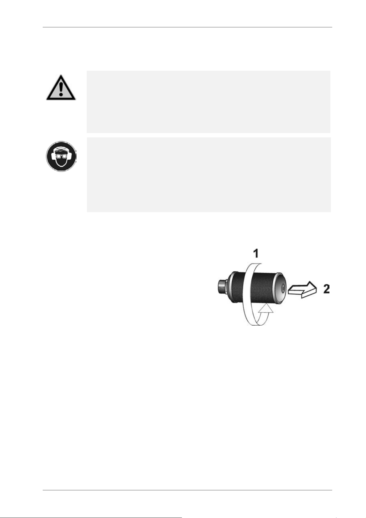
Renew muffler
► Depressurise the dryer and shut it down (see page 43).
► Unscrew muffler as shown in the
opposite figure.
► Replace muffler and secure it.
Undo muffler
► Restart dryer (see page 44).
HDK350_EN_01_2005-05-10 49

Maintenance work to be completed every 12 months
Recalibration of dewpoint sensor (optional)
In order to ensure accurate dewpoint measuring, we recommend
recalibrating the dewpoint sensor
at least every 12 months. The
recalibration must be carried out
by the manufacturer. This period
depends however on the actual
application and might thus be
extended accordingly.
Dewpoint sensor (1)
Warning!
The dew point sensor is a sensitive measuring dev ice. It can be damaged if
subjected to forceful vibrations or shocks. Therefore, please handle the
dew point sensor w ith great care at all times.
For calibration, the pressure dewpoint sensor must be dismantled. In order to
limit the impact on the dryer operation to a minimum, we recommend that you
contact the manufacturer well in advance (for contact details, see page 9) and
order a new dewpoint sensor. Upon receipt of your old pressure dewpoint sensor,
we will issue a credit note.
After receipt of the new pressure dewpoint sensor, replace the sensor as follows:
► Hold the box of the dewpoint sensor ready.
► Release pressure from dryer and shut down the unit (see page 43).
Installing / dismantling pressure dewpoint sensor
50 HDK350_EN_01_2005-05-10

Maintenance and repair of the dryer
► Loosen the screw at the adapter (1) and disconnect signal cable with the
adapter and seal.
► Remove dewpoint sensor from the sensor cell (3) by turning the nut (2).
► Take the new dewpoint sensor (2) from the box, remove the protective caps
(4, 5) and screw it into the sensor chamber (3).
► Place seal onto sealing face; connect adapter (1) and secure it by tightening
the screw.
► If no other maintenance work is to be carried out: Restart the dryer (see
page 44).
Note:
For posting, the dewpoint sensor must be equipped w ith protective
caps and placed in a solid box.
► Place the protective caps (4, 5) onto the old dewpoint sensor and pack it
properly in the box.
► Send the old dewpoint sensor to the manufacturer.
Clean or replace check valves
Check valves are wear parts and should be cleaned, or replaced, every 12
mo nt hs.
► Release pressure from dryer and shut down the unit (see page 43).
► Remove check valves from the pipe bridge by opening the threaded joints.
Observe direction of rotation for upper (1) and lower (2) pipe bridge (see
figures below).
Dismantling of check valves
► Disassemble check valves and clean all parts.
► Worn or damaged check valves must be replaced.
► Remount the check valve in the pipe bridge.
► If no other maintenance work is to be carried out: Restart dryer (see page
44). Check co nnection for tightness.
HDK350_EN_01_2005-05-10 51

Maintenance work to be completed every 48 months
Maintenance work to be completed every 48 months
To complete the following maintenance tasks, yo u must dismantle the pipe
bridges and the vessels. We therefore recommend that you carry out these tasks
together.
Note:
In accordance with national regulations, a pressure vessel inspection
may be prescribed to be carried out at regular intervals by an
independent supervisory office.
For an inspection of the pressure vessels, the drying agent must be
removed as described as follows.
When inspecting the pressure vessels, it is recommended to check the
condition of all fittings such as e.g. sieve bottoms and dust sieves,
including gaskets. If necessary, these fittings must be cleaned or
renew ed.
In the event of comprehensive maintenance or repair tasks, contact
the manufacturer (see page 9).
Renew drying agent
The service life of the drying agent is usually approx. 3 to 5 years. However, in
favourable installation conditions, the change of drying agent may be carried out
at a substantially later date (for notes on the installation site, see also page 24).
The change interval depends very significantly from the degree of contamination
in the compressed air (or the quality of the compressed air upstream filters). Oil,
dust, and dirt particles cover the drying agent surface and reduce its effective
surface, in part quite irreversibly.
If in doubt, have a sample of your drying agent assessed by specialists. Send a
sample of approx. 200 g to the manufacturer (for address, see page 9).
Note:
The vessels are equipped with dust sieves that hold back drying agent
dust particles. If these dust sieves are blocked, back pressure is built
up, which might affect the proper functioning of the dryer.
We therefore recommend cleaning, or replacing, the dust sieves each
time the drying agent is replaced.
Comply with the following safety notes when changi ng the drying agent:
52 HDK350_EN_01_2005-05-10

Maintenance and repair of the dryer
Wear eye protection and dust mask due to increased dust generation!
When emptying the drying agent, increased dust generation may occur.
In order to avoid any eye irritations, w ear protective goggles!
In order to avoid any dust inhalation, w ear dust mask!
Risk of skidding!
If drying agent has been spilt on the floor, there is a risk of skidding
caused by the drying agent beads. Therefore, spilt drying agent must
always be taken up immediately.
Remove used drying agent
► Depressurise dryer and take out of service (see page 43).
► Place a suitable collecting vessel underneath the unit.
► Disconnect the control block from the upstream filter (1).
► Loosen the connection between the lower pipe bridge and the vessels (2).
► Disconnect the solenoid valve block (3).
Dismantling of the lower pipe bridge
► Remove the dust sieves from the vessels.
► Clean dust sieves with compressed air or a wire brush. If necessary, replace
the dust sieves.
► Drain drying agent into the collecting vessel. Remove all residue from the
vessels, using an industrial vacuum cleaner.
► Insert cleaned or new dust sieves.
► Reconnect all pipelines and cables.
HDK350_EN_01_2005-05-10 53
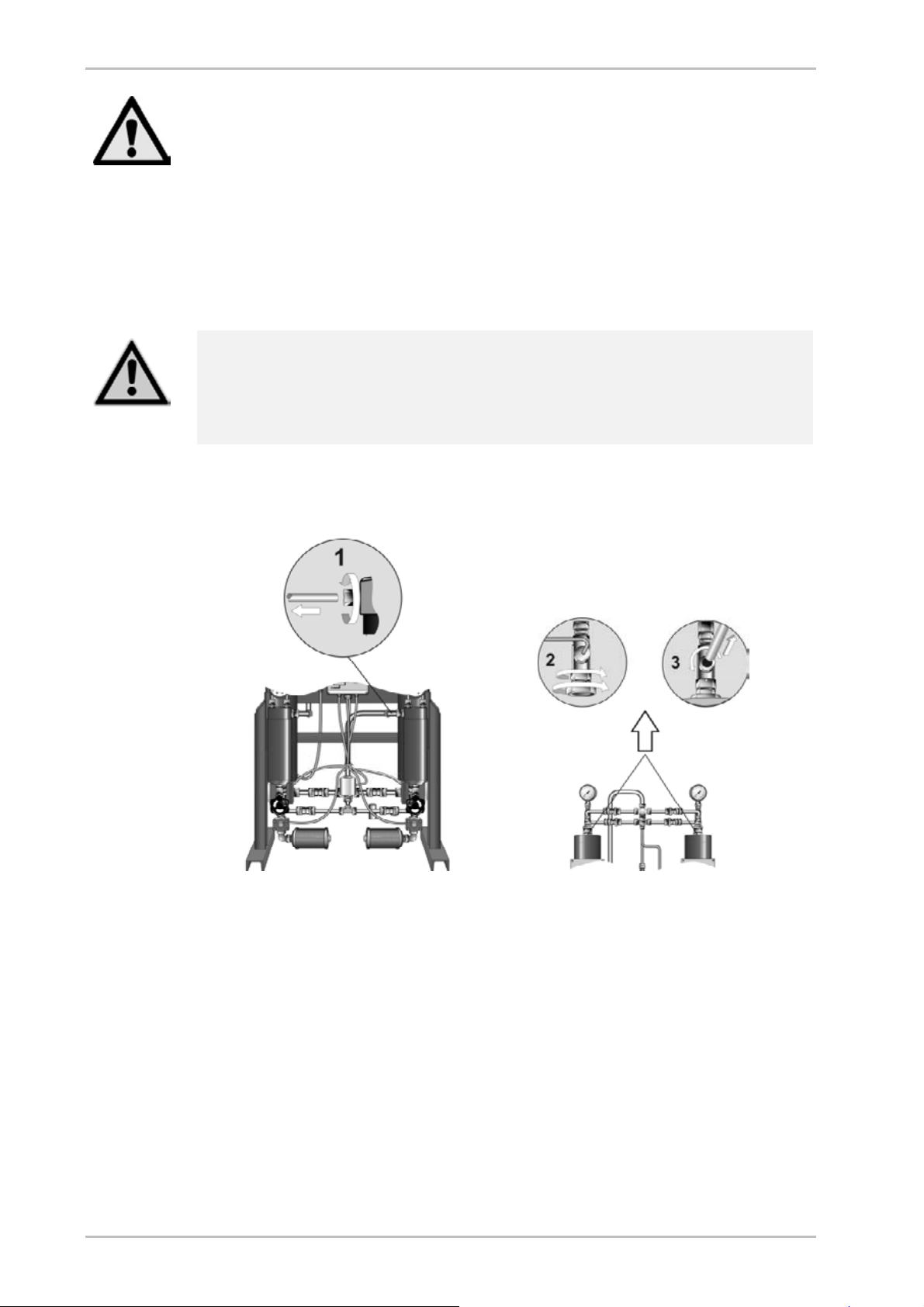
Maintenance work to be completed every 48 months
Warning!
If the dryer is not used within specifications, the drying agent can be contaminated with pollutants. Always take this into account for the environmentally
safe disposal of the drying agent. The waste code numbers of the drying agent
can be obtained from the manufacturer (see page 9).
► Dispose of the used drying agent in accordance with all applicable
regulatio ns.
Fill with new drying agent
Risk of falls!
The dryer must not be misused as a climbing aid! The components have
not been designed for such loads and could fracture.
Only use approved climbing aids when filling the vessels.
► Loosen connection at the pressure plate (1).
► Loosen connection at the pressure reducer (2).
► Disconnect the upper pipe bridge from the vessels (3).
Dismantling of upper pipe bridge
► Remove the dust sieves from the vessels.
► Clean dust siev es with compressed air or a wire brush. If necessary, replace
the dust sieves.
► Fill the several drying agents in as separate layers (according to the technical
data in the appendix).
► If necessary, use a funnel. Take special note of the next step:
► Provide for a high bulk density in the vessel.
54 HDK350_EN_01_2005-05-10

Maintenance and repair of the dryer
Note:
To achieve an optimum bulk density, we recommend using a
"snowstorm" filling pipe available from the manufacturer.
► Otherwise use a rubber hammer to tap regularly against the vessel wall
during filling or use a rod to distribute and compact the drying agent through
the vessel opening.
► Repeat the process on the seco nd vessel.
► Insert cleaned or new dust sieves.
► Reconnect all pipelines.
► Restart dryer (see page 44). C heck that the connection is leak tight.
► Complete two dryer cycles, the shut down the unit.
► Replace muffler as described on page 49.
HDK350_EN_01_2005-05-10 55

Summary of faults
Identify and eliminate faults
The following table provides information on what designatory abbreviations are to
be used for the various components. These designations are also found in the
technical documentation.
Used abbreviation Component
B1/B2 Vessel
PDI Differential pressure gauge
PI Pressure gauge
V1, V2
V3, V4, V5, V6, V10, V11
V9
V7, V8 Expa nsio n va lve
Summary of faults
There are different fault types. In the case of most electrical faults (e. g. short
circuit, defective fuse etc.) the mai n valves close. In the case of some process
faults, the dryer will continue to operate for some time. Faults o n the dryer
become noticeable e.g. due to unusual noises and dam pressures.
The following table shows who is allowed to remedy a fault: the owner's specialist
personnel or the manufacturer's service engineer.
Table of possible faults
Certain faults must be due to valves that are not properly opened/closed. For
measures to be taken i n such cases, please refer to the bottom of the table.
Main valves
Check valves
Pressure build-up valve
56 HDK350_EN_01_2005-05-10

Fault Possible cause Remedy
Dewpoint is not reached
Operating pressure too low Increase operating pressure
Excessive differential pressure at
upstream filter
Compressed air volume flow too high Reduce compressed air volume flow.
Inlet temperature of compressed air
too high
Condensate trap (optional) at the
upstream filter is not working properly
Drying agent contaminated or out of
date
Control board defective Check fuses (switchbox, supply line);
Insufficient regeneration gas Check function of valve V7/V8 and
Check differential pressure at the
upstream filter; replace filter element, if
necessary.
Reduce inlet temperature of
compressed air or install preliminary
compressed air cooler.
Check condensate trap (optional); clean
or replace, if necessary.
Inspect upstream filter for
contamination; replace filter element, if
necessary.
Inspect drying agent for contamination;
replace, if necessary.
replace board, if necessary.
muffler; replace filter element of muffler,
if necessary.
Identify and eliminate faults
Specialised
personnel
Service technician
z
z
z
zz
zz
z
zz
z
zz
Pressure in vessel too
low
Backpressure during
regeneration too high
No pressure build-up
Excessive compressed
air consumption
Dryer fails to switch over
Excessive differential pressure at
upstream filter
Muffler contaminated Check muffler for contamination; clean
Valve V7/V8 does not open properly see *
Dust filters blocked
Compressed pressure system
upstream from the dryer is not
pressurised
Valve V1/V2 or V9 does not open
properly.
Condensate trap (optional) at the
upstream filter is not working properly
Valve V7/V8 does not open properly see *
Compressor is switched off Check compressor synchronisation.
Power supply interrupted, cable
broken.
Valve V1/V2 does not open properly see *
Error in control programme Restart programme. z
Control board defective Check fuses (switchbox, supply line);
Check differential pressure at the
upstream filter; replace filter element, if
necessary.
or replace, if necessary.
Clean or replace dust filters..
Check whether the compressed
pressure system upstream from the
dryer is pressurised. Eliminate any
faults in the compressed air system.
see *
Check condensate trap (optional); clean
or replace, if necessary.
Reconnect the unit to the power supply.
replace board, if necessary.
z
zz
zz
z
zz
z
z
zz
HDK350_EN_01_2005-05-10 57

Summary of faults
Fault Possible cause Remedy
No expansion in
chamber
Valve V7/V8 does not open properly see *
Specialised
personnel
Service technician
Valve V7/V8 does not close properlyDryer is continuously
bled
Dryer is bled excessively Valves V1/V2, V3, V4, V5, V6 do not
* Valve fails to open or close properly
Valve V1/V2 does not close properly
close properly
Check supply voltage.
Check whether coil is properly mounted.
Inspect valve for contamination; clean
or replace, if necessary.
Check voltage at cables, contacts and
coils; replace, if necessary.
With dewpoint-sensing control (optional)
Fault code Description of fault Possible cause Remedy
+20
999
sens
or
–999
Upper measuring range
limit exceeded
Dewpoint sensor
defective
Sensor not powered, or
cable or sensor defective
Drying capacity
exceeded.
Error in programme. Restart programme. z
Sensor defective or
irreversibly
contaminated.
Sensor, sensor cable
or sensor adapter
defective.
See instructions for commissioning.
If the drying agent is wet, replace it.
Replace sensor.
Visual inspection; check power
supply (24 V to terminals 4 and 6).
Replace defective component(s).
see *
see *
zz
zz
zz
z
Specialised
personnel
Service technician
z
z
z
58 HDK350_EN_01_2005-05-10

Index
A
Abbreviation
components.......................................................... 56
Address, manufacturer............................................... 9
Adsorption, explanation............................................ 19
air ejection
hazard .................................................................. 13
Auxiliary heater.........................................................21
B
Bolt connections....................................................... 28
Build no. ................................................................... 45
C
Changing cycle mode
explanation........................................................... 39
Check valves
maintenance interval............................................ 46
Components............................................................. 56
Compressed air.................................................. 14, 19
Compressor synchronisation.................................... 21
option ...................................................................21
Compressor synchronisation line
installation ............................................................ 30
Connection lines....................................................... 29
Connector
electrical............................................................... 30
Consumables ............................................................. 9
Control
dewpoint-sensing ................................................. 21
Control cabinet......................................................... 18
Control system
pneumatic............................................................. 21
signalling contacts................................................ 21
Conversions ............................................................. 14
Cycle
fixed...................................................................... 21
variable................................................................. 21
Cycle mode change
explanation........................................................... 39
Index
Design
paint compatible ................................................... 22
Dew point sensor
maintenance interval ............................................ 46
Dewpoint-sensing control.........................................21
Digital display
explanation...........................................................35
Documentation, technical.........................................62
Dryer
maintenance interval ............................................ 46
drying agent
service life ............................................................52
Drying agent
charging................................................................21
maintenance interval ............................................ 46
storage .................................................................27
drying agents
handling................................................................ 14
dust generation...................................................14, 53
dust mask.................................................................14
Dust sieves
maintenance interval ............................................ 46
E
Ear protection.....................................................16, 36
electrical voltage, hazard..........................................13
Example for installation ............................................ 29
Expansion, explanation ............................................ 19
F
Fabrication no.............................................................5
Factory settings........................................................16
Filter elements
maintenance interval ............................................ 46
Fixed cycle................................................................21
Flow diagram............................................................ 70
Fluid group ...............................................................64
H
hazard areas.............................................................13
Humidity....................................................................64
D
Danger notes
Danger! ................................................................11
Danger warning, maintenance ................................. 47
Date of manufacture................................................... 5
Dehumidification
explanation........................................................... 19
HDK350_EN_01_2005-05-10 59
I
Installation area........................................................24
Installation example..................................................29
Installation site, requirements...................................24

L
LEDs
explanation........................................................... 34
Liability..................................................................... 10
lifting gear .......................................................... 15, 23
Limits, permissible.............................................. 16, 37
M
Machine damage, prevention................................... 12
Machine passport....................................................... 5
Mains voltage........................................................... 64
Maintenance
check valves ........................................................ 51
dam pressure....................................................... 47
differential pressure ............................................. 48
drying agent ......................................................... 52
Muffler.................................................................. 49
replacement of filter element................................ 48
sensor .................................................................. 50
Maintenance contract............................................... 45
Maintenance, danger warnings................................ 47
Manometer
pressure reducer.................................................. 36
Media
aggressive............................................................ 10
Misuse...................................................................... 14
Misuse, suspected ................................................... 14
Modifications on the dryer........................................ 14
Muffler
maintenance interval............................................ 46
N
Noise level ............................................................... 64
Notes
safe, efficient handling ......................................... 11
O
On/Off switch
explanation........................................................... 33
On/Off-Switch........................................................... 18
Operating instructions.............................................. 10
safe place............................................................. 11
safety notes.......................................................... 12
target group.......................................................... 11
Operating overpressure
minimum, maximum............................................. 64
Operating pressure .................................................. 38
permissible............................................................. 5
safety device........................................................ 28
Operating signalling contact
installation............................................................ 31
Operation signalling
contact.................................................................. 21
Original replacement parts................................. 17, 45
Outside installation................................................... 20
overpressure, hazard ............................................... 13
P
Packaging ................................................................23
Parameters
preset ................................................................... 10
Personnel qualification........................... 10, 12, 14, 47
Power supply
interrupted............................................................ 42
Pressure build-up
explanation........................................................... 20
sudden .................................................................37
Pressure reducer
maintenance interval............................................ 46
pressure vessel.................................................. 16, 45
Programme
sequence, steps................................................... 68
Protection class........................................................ 64
R
Regeneration, explanation ....................................... 19
Regulations for accident prevention......................... 23
Repairs, telephone number........................................ 9
Replacement parts............................................. 17, 45
Restart
pressure conditions.............................................. 44
S
Safety notes ............................................................. 12
general ................................................................. 14
operating phases.................................................. 15
Warning!............................................................... 11
Safety valves...................................................... 28, 32
Service, telephone number ........................................ 9
Shutdown valves...................................................... 29
Shutting down ..........................................................43
emergency............................................................43
Signalling lines
external.................................................................30
skid risk .................................................................... 13
Skidding risk
charging drying agent........................................... 53
Snowstorm filling pipe
charging drying agent........................................... 55
Specialist personnel........................................... 11, 28
Stand profiles ........................................................... 25
Standard equipment................................................. 10
Start-up device......................................................... 20
Start-up, requirements..............................................32
Storage room
60 HDK350_EN_01_2005-05-10

Index
requirements ........................................................ 26
Supply cable, electrical ............................................29
Supply lines.............................................................. 28
Switching off............................................................. 42
symbols, explanation................................................ 13
T
Target group ............................................................ 11
Temperature, ambient
minimum, maximum ............................................. 64
Transport damage.................................................... 23
Type plate ................................................................12
U
Use, intended........................................................... 14
Use, safe .................................................................. 11
V
Variable cycle...........................................................21
Vessel pressure gauge
maintenance interval ............................................ 46
vibration dampers..................................................... 26
Visual inspection.......................................................47
Voltage
electrical ............................................................... 29
W
Warranty................................................................... 10
Waste code numbers................................................17
HDK350_EN_01_2005-05-10 61

Annex with technical documentation
This annex comprises the following information and technical documentation:
Technical data
Replacement and wear parts list
Logic control diagram
Flow diagram
Dimensional drawing
62 HDK350_EN_01_2005-05-10

Technical data
Annex with technical documentation
Capacity* Length Height Width Weight
Type
HDK 50/100 50 635 1155 400 100
HDK 80/100 80 635 1205 400 110
HDK 140/100 115 685 1220 400 110
HDK 250/100 240 740 1350 450 144
HDK 400/100 370 810 1410 450 200
HDK 600/100 580 870 1710 450 275
HDK 50/250 80 635 1155 400 110
HDK 80/250 140 635 1205 400 115
HDK 140/250 205 685 1220 400 132
HDK 250/250 420 740 1350 450 195
HDK 400/250 655 810 1410 450 245
m3/h mm mm mm kg
100 bar
250 bar
HDK 600/250 1020 870 1710 450 375
350 bar
HDK 50/350 130 635 1155 400 110
HDK 80/350 180 635 1205 400 115
HDK 140/350 255 685 1220 400 145
HDK 350/350 520 740 1350 450 225
HDK 400/350 367 810 1410 450 280
HDK 600/350 1280 870 1710 450 415
* relative to 1 bar (abs.) and 20 °C (68 °F) at 7 bar operating pressure and a feed temperature of 35 °C (95 °F).
HDK350_EN_01_2005-05-10 63

Technical data
Type HDK 50/100–600/350
Fluid group (acc. to 97/23/EC) 2
max. operating overpressure 100/250/350 bar
min. operating overpressure 10 bar
min. ambient temperature ≥+1 °C (33,8 ° F)
max. ambient temperature ≤+50 °C (122 ° F)
Rel. humidity ≤ 60 %
Noise level : +3 dB (A) relative to free field measurement, 1 m surr.
65 – 95 dB(A)
field
Mains voltage (see type plate)
Protection class IP 65
Filling quantity Drying agent per vessel
Top MS512 80 %
Bottom Ecosorb IIa 20 %
64 HDK350_EN_01_2005-05-10

Annex with technical documentation
Replacement and wear parts list
Items see dimensio n drawing.
Type HDK 100/250/350 bar
Item Designation 50/... 80/... 140/... 250/...
1 Vessel
5 Ecosorb IIa 675010025502
6 Molecular screen MS512 675010051201
7 Dust sieve 799020002003 799020003202
2 Upstream filter G3XP G5XP G7XP G9XP
2.3 Filter element 1050 XP 211010010508 — — —
2.3 Filter element 1070 XP — 211010010706 — —
2.3 Filter element 1140 XP — — 211010011411 —
2.3 Filterelement 2010 XP — — — 211010020110
Manual drain EV05 631120008001
Condensate trap (optional)
Trap 2/250
Trap 2/400
Differential pressure gauge
HZD80, 420 bar 104000008000
104100000016
104100000018
3 Downstream filter G3V G5V G7V G9V
3.3 Filter element 1050 V 211040010500 — — —
3.3 Filter element 1070 V — 211040010700 — —
3.3 Filter element 1140 V — — 211040011410 —
3.3 Filter element 2010 V — — — 211040020110
Manual drain EV05 631120008001
Differential pressure gauge
HZD80, 420 bar 104000008000
12 Control system
95 Dew point sensor (option) 655000010001
17 Pressure reducer
21 Muffler, complete
657500010010
672200001501
HDK350_EN_01_2005-05-10 65

Replacement and wear parts list
Type HDK 100/250/350 bar
Item Designation 50/... 80/... 140/... 250/...
Valves
9 Pressure build up valve, Expansion
valves, DN 6
10 Main valve DN 12 641400023001
13 Check valve ø 16 620300001629
14 Check valve ø 8 620300000825
15 Check valve ø 8 620300000840
641400023001
Manometer
18 Vessel manometer
50-250/100 bar 50-250/250 bar 50-250/350 bar
650200032221 650200032521 650200032621
66 HDK350_EN_01_2005-05-10

Annex with technical documentation
Type HDK 100/250/350 bar
Item Designation 400/... 600/...
1 Vessel
5 Ecosorb IIa 675010025502
6 Molecular screen MS512 675010051201
7 Dust sieve 799020003202
2 Upstream filter G7XP G11XP
2.3 Filter element 1140 XP 211010011411 —
2.3 Filter element 2020 XP — 211010020208
Manual drain EV05 631120008001
Condensate trap (optional)
Trap 2/250
Trap 2/400
Differential pressure gauge
HZD80, 420 bar 104000008000
104100000016
104100000018
3 Downstream filter G7V G11V
3.3 Filter element 1140 V 211040011410 —
3.3 Filter element 2020 V — 211040020200
Manual drain EV05 631120008001
Differential pressure gauge
HZD80, 420 bar 104000008000
12 Control system
95 Dew point sensor (option) 655000010001
17 Pressure reducer
21 Muffler, complete
657500010010
672200001501
Valves
9 Pressure build up valve,
Expansion valves, DN 6
10 Main valve DN 12 641400023002
13 Check valve ø 20 620300002010
14 Check valve ø 8 620300000825
15 Check valve ø 8 620300000840
641400023001
Manometer
18 Vessel manometer
400-600/100 bar 400-600/250 bar 400-600/350 bar
650200032222 650200032521 650200032622
HDK350_EN_01_2005-05-10 67

Logic control diagram
Logic control diagram
Adsorption in B1 and regeneration in B2
68 HDK350_EN_01_2005-05-10

Regeneration in B1 and adsorption in B2
Annex with technical documentation
HDK350_EN_01_2005-05-10 69

Flow diagram
Flow diagram
Item Designation Item Designation
1 Vessel 12 Control cabinet
2 Upstream filter 13, 14, 15 Check valves
3 Downstream filter 17 Pressure reducer
7 Dust sieve 18 Vessel manometer
9 Pressure build up valve 21 Muffler
10 Main valve
70 HDK350_EN_01_2005-05-10

Dimensional drawing
Annex with technical documentation
Dimensions (mm)
Connection G 1/2 “ G 1/2 “ G 1/2 “ G 1/2 “ G 3/4 “ G 3/4 “
Type HDK 100/250/350 bar
50/... 80/... 140/... 250/... 400/... 600/...
A 640 640 640 775 845 905
B 1155 1205 1220 1350 1410 1710
C 400 400 400 450 450 450
HDK350_EN_01_2005-05-10 71

Dimensional drawing
Items
Option
72 HDK350_EN_01_2005-05-10
 Loading...