

Page 1

INSTALLATION,
OPERATION
&
MAINTENANCE
MANUAL
VERTICAL PACKAGED UNITS
'PV' SERIES
MODELS: PV036 - PV060
Page 2

INDEX
Contents Page
General
Model decoding ...................................................................................................................................................... 2
General statement .................................................................................................................................................. 3
Warranty ................................................................................................................................................................. 3
Safety issues .......................................................................................................................................................... 3
Inspection for damage ............................................................................................................................................ 3
Installation instructions
General................................................................................................................................................................... 3
Location of unit ....................................................................................................................................................... 3
Condensate drain connection................................................................................................................................. 4
Duct connection...................................................................................................................................................... 4
Electrical controls ................................................................................................................................................... 4
Cable size............................................................................................................................................................... 4
Unit dimensions ...................................................................................................................................................... 5
Access details ........................................................................................................................................................ 6
Operation instructions
Start-up inspection & check list .............................................................................................................................. 7
Electrical data ......................................................................................................................................................... 8
Maintenance instructions
Crankcase heater ................................................................................................................................................... 9
Cleaning of coils & filters ........................................................................................................................................ 9
Preventive maintenance schedule ....................................................................................................................... 10
Trouble shooting chart ..................................................................................................................................... 11-12
Typical schematic wiring diagram....................................................................................................................13-14
Parts list ................................................................................................................................................................ 15
CONTINUING RESEARCH RESULTS IN STEADY IMPROVEMENTS.
THEREFORE, THESE SPECIFICATIONS ARE SUBJECT TO CHANGE WITHOUT NOTICE.
1
Page 3
20
ACCESS
19
DIS-
AIR)
CHARGE
(SUPPLY
R :RH
F: FRONT
L :LH
18
OPTIONS
17
APPLICATIONS
16
UNIT
ACCESSORIES
15
FILTER
14
COIL
CONDENSER
13
COIL
EVAPORATOR
12
COND.
MOTOR
N : STD.
APPLICATION
TION
N : STANDARD
C :COMMUNICA-
N : STD. UNIT
2"
PLEATED
FILTER
N :NO
G:
A :ALUMINUM
FIN
B : COATED
A :ALUMINUM
FIN
B : COATED
N :STD.
SHELTER
APPLICATION
FILTER
ALUMINUM
FIN
C :COPPER
ALUMINUM
FIN
C :COPPER FIN
FIN
11
HEATER
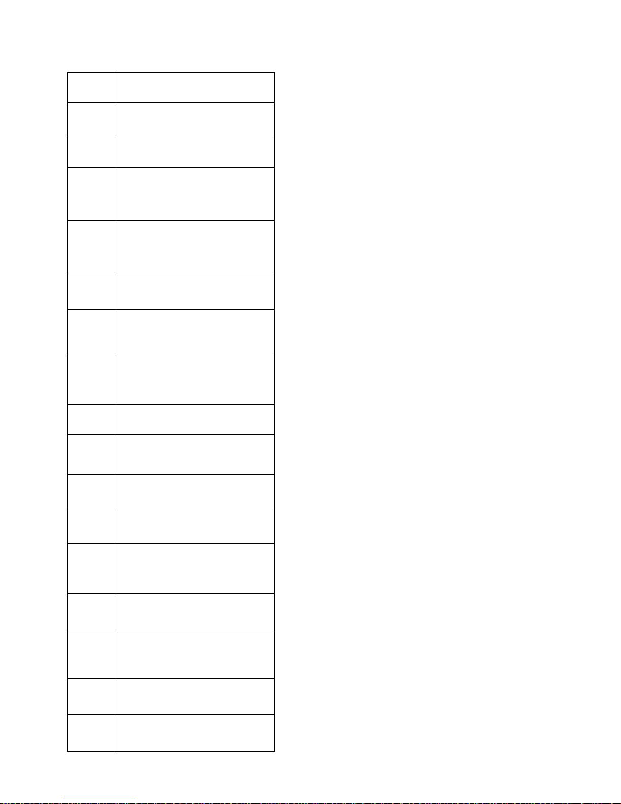
MODEL DECODING
10
DRIVE
9
BLOWER
8
COMPRESSOR
OPTIONS
MOTOR
TYPE
N :NO
HEATER
N :DIRECT
DRIVE
MOTOR
V : STD.
HERMETIC
S : SCROLL
CATING
HERMETIC
R :RECIPRO-
7
RATION
CIRCUIT
REFRIGE-
S : SINGLE
*
6
SUPPLY
( V-Ph-Hz )
ELECTRICAL
3, 4 & 5
NOMINAL
COOLING
CAPACITY
1& 2
BASIC
(MBH)
(4 WIRE)
H :208/230-3-60
M: 380-3-60
036
048
060
PV
UNIT
VERTICAL
PACKAGED
Not available for PV036.
*
NOTE:
2
Page 4
GENERAL
GENERAL STATEMENT
This unit is from the PV series that was designed & built for the optimum performance. However, it is required that you become well
acquainted with good practices for the proper installation/operation/and maintenance procedures in order to ensure a safe trouble free
operation, year after year.
Please read through the whole manual contents before you attempt to install/operate/ and maintain the unit.
Most of the procedures described in this manual require certain skills and experience. The installation and other maintenance procedures
should be performed only by highly skilled and experienced technicians. The end user’s role should be limited to the cleaning of the
filter. Please consult your nearest "Zamil" representative for further information.
WARRANTY
All of the PV series of Vertical Packaged Units are covered by the standard warranty terms against any manufacturer defect. Should
you encounter any problem that falls under the warranty terms please contact your nearest "Zamil" representative.
SAFETY ISSUES
There are three degrees of safety hazards that are identified throughout this manual as WARNING (where the situation will result in
personal injury), CAUTION (where personal injury might occur), and ATTENTION (where minor personal injury and/or property damage could happen). Please understand and respect those identifications.
WARNING: The PV units operate on a high voltage with moving parts (at high speed) which can lead to serious injuries and/
or damage to the unit. Never attempt to service the unit unless the main electrical power supply has been disconnected.
CAUTION: Extra care should be observed when installing, test running, adjusting, servicing, or maintaining the unit as the
hazard of explosion, fire, electrical shock, and potential personal injury and property damage are present.
When performing any task pertaining to the installation and maintenance of the unit, the skilled technician should observe all the
applicable safety measures (wear of safety helmet, boots, gloves, and goggles. Use of proper handling materials for brazing and use
of wet cloth for quenching. A fire extinguisher should be easily accessible etc.). He should also read all the instructions and information
in this Manual prior to attempting to perform any installation or servicing of the unit. All applicable local codes should also be observed.
INSPECTION FOR DAMAGE
The unit should be carefully inspected visually for any sign of physical damage due to mishandling. Whenever a damage is detected,
please indicate it on the corresponding delivery note before you sign it and inform your nearest "Zamil" office.
INSTALLATION INSTRUCTIONS
GENERAL
These units are shipped completely assembled, charged and wired. They do not require any field installation of refrigerant tubing.
Units require external power, thermostat wiring, condensate drain piping and ducting as applicable.
Size of unit for an installation should be based on a heat gain calculation made according to applicable standards. Units must also be
installed in accordance with regulations of the "National Fire Protection Association" and local electrical codes. Where local regulations
conflicts with the instructions in this manual, installer should adhere to local standards.
These units are wall mounted outside the building and proper openings in the wall should be given for return & supply air flows. Unit
should be installed and erected properly to prevent it from falling down.
LOCATION OF UNIT
When selecting the location for the unit, the following points should be kept in mind:
1. Provisions to fix the unit on walls.
2. That the terrain allows for drainage away from the unit.
3. Availability of electric power.
4. To position the unit for unrestricted air circulation of the condenser air inlet on the free side.
5. Check minimum clearances required for your unit, with regard to walls, or other obstructions.
6. Care should be taken to prevent air from other sources from entering condenser, if this air is at a high temperature.
7. Level the unit on its final location and be sure that the levelling tolerance is ±5 mm per linear meter in any direction.
CAUTION: Do not install the unit as indoor unit, install it in an open area, and unit air inlets must not be located near exhaust
vents or other source of contaminated air.
3
Page 5
CONDENSATE DRAIN CONNECTION
• Use standard PVC pipe with NPT connection for the condensate drain. The plastic drain pan has an internal built-in trap. Accord-
ingly there will be no need for external 'P' trap.
• Piping has to be sloped away from the unit.
• Remember to remove the drain hole plug before operating the unit. Avoid bends & elbows.
DUCT CONNECTION
The units can be connected to the ducting in either vertical or horizontal configuration. Just remove the dummy panels and connect
using flexible duct connection. The duct should be properly designed and the drive package should match the required CFM &
corresponding external static pressure.
ELECTRICAL CONTROLS
1. For normal air-conditioning applications
This packaged unit control consists of Systemizer
(a) Compressor Lockout. If any of the unit’s safety controls trips due to abnormal conditions the Electronic Controls lockout the
compressor, preventing restart, unless attended by service personnel. The unit can be re-started only by reset of thermostat after
ensuring safe system conditions.
(b) Anti recycle timer for compressor safety in case of accidental manual reset or immediate recycling of thermostat due to load
demand.
(c) Indicator LED lights:
Green – Power ON.
Red – Fault indication.
(d) Typical single stage thermostats to be ordered (part number 800-645-31).
2. For communication shelter applications (To be ordered separately)
The set of two PV units (when used for communication shelter applications) is provided with a dedicated control with the following features:
(a) Auto-reset High Pressure Switch: Built in lockout circuit with auto reset. Provides protection to the compressor.
(b) Auto reset Low Pressure Switch: Built in lockout circuit and low-pressure timed bypass circuit.
(c) Microprocessor based electronic board provides the compressor lockout, if any of the unit safety controls trip due to abnormal conditions.
(d) Auto lead/lag controller: The Auto lead/lag controller is a complete control package designed to operate a fully or partially
redundant air conditioning system having two units paired together. It consists of a thermostat and solid state timer with selectable
change-over intervals (typical 7 days). This control unit is factory-wired, tested and mounted in separate enclosure for quick
installation inside the air-conditioned space.
(e) Low ambient control: By using automatic condenser fan speed controls.
TM
Microprocessor Based Electronic Control Board, incorporating the following features:
CABLE SIZE
• All wiring should be in accordance with local standards.
• Before making any connection, check the electric power supply, it must have the same characteristics as what is displayed in the nameplate.
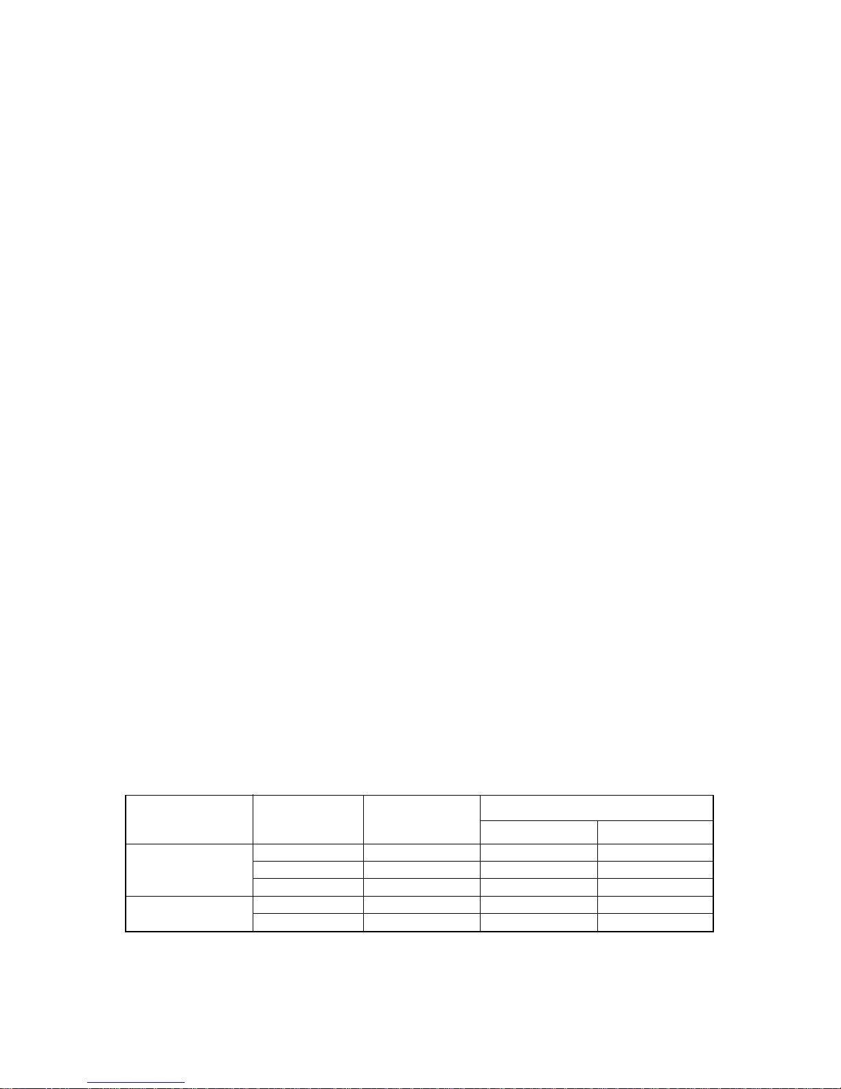
• For selecting cable size, refer to wire ampacity table at different MCA (Minimum Circuit Amps) provided in unit electrical data, which
is listed as a guideline (see table below).
• Wiring connection to the unit must have suitable insulation of a minimum temperature of 60
POWER SUPPL Y
208/230V-3Ph-60Hz
380V-3Ph-60Hz
LEGEND: MCA - Minimum Circuit Amps
NOTES: 1. Customer is to select cable size also with cross reference as per cable manufacturer data for voltage reduction per unit
length. The above cable ampacity table is for guidance only.
2. The selected cables for specified units is as per following characteristics:
a. Unit without electric heaters.
b. Any extra electrical accessories shall add to MCA rate, for more information, refer to unit electrical tables in the catalog.
MODEL No. MCA
0
C.
CONDUCTOR SIZE
PV036 19.7 14 2.5
PV048 27.2 10 6.0
PV060 32.6 10 6.0
PV048 18.3 14 2.5
PV060 20.0 14 2.5
4
AWG - MCM METRIC - MMSQ
Page 6
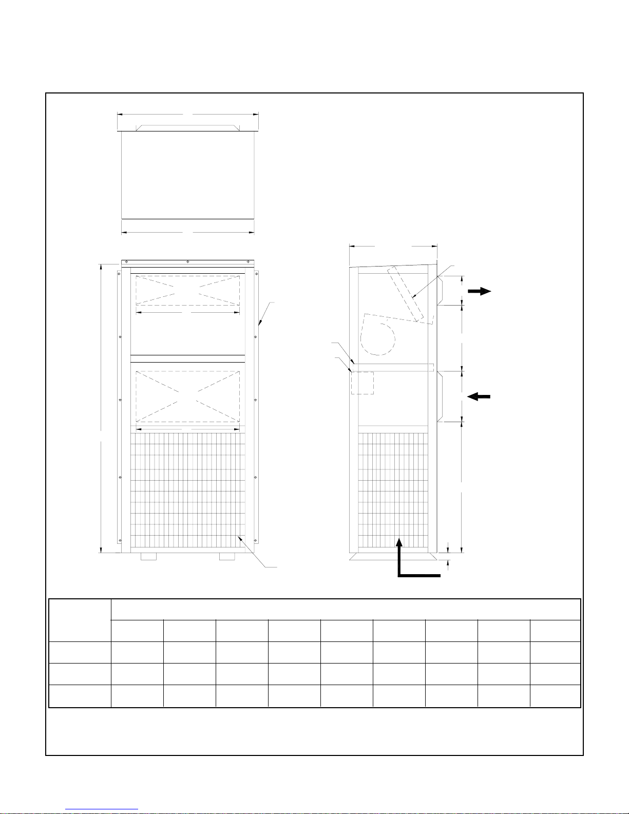
DIMENSIONS
B
C
TOP VIEW
SUPPLY AIR OPENING
F
RETURN AIR OPENING
PV036 - PV060
MOUNTING FLANGE
FILTER
CONTROL BOX
610 [24]
EVAPORATOR COIL
G
SUPPLY AIR
E
I
RETURN AIR
H
CONDENSER COIL
DIMENSIONS
BCDE
980 (38.6)
1143 (45)
1143 (45)
920 (36.2)
1067 (42)
1067 (42)
908 (35.8)
662 (26.1)
662 (26.1)
457 (18)
762 (30)
762 (30)
END VIEW
FH
762 (30)
767 (30.2)
767 (30.2)
D
51 [2]
COND. AIR INLET
G I
203 (8)
251 (9.9)
251 (9.9)
762 (30)
759 (29.9)
759 (29.9)
MODEL
NUMBER
PV036
PV048
PV060
A
FRONT VIEW
A
2000 (78.7)
2134 (84)
2134 (84)
NOTES:
1. All dimensions are in millimeters, (dimensions in brackets are in inches).
2. Service clearance should be 915 mm (3 feet) on all sides (other than the front supply & return air opening side).
350 (13.8)
403 (15.9)
403 (15.9)
5
Page 7
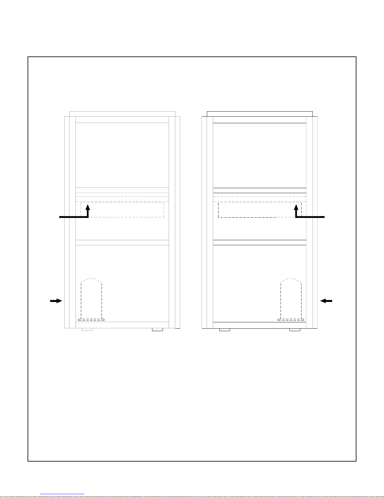
ACCESS DETAILS
PV036 - PV060
FILTER & ELE. CON T RO LS
(FROM BACK SIDE)
COMPRESSOR ACCESS
(FROM SIDE)
LEFT SIDE ACCESS
RIGHT SIDE ACCESS
FILTER & ELE. CONTROLS
(FROM BACK SIDE)
COMPRESSOR ACCESS
(FROM SIDE)
6
Page 8

OPERATION INSTRUCTIONS
START-UP INSPECTION & CHECK LIST
After the installation is completed in all respect, the following points should be covered before the system is switched on for operation.
1. Check unit location as per installation instructions.
2. Make sure all electrical fasteners/connections are tight and clean.
3. All controls are set according to manufacturer's instructions (low & high pressure switch, fan cycling switch, etc...)
4. Follow all the instructions from the warning tags and stickers.
5. Check if condenser & blower fan are free to turn without wobbling.
6. Remove straps & wooden pieces that holds the compressor in place during transportation.
7. Compressor crankcase heater should be energized for 24 hours prior to system start-up.
8. Circuit breaker/fused disconnect switch.
9. All piping, piping insulation and piping supports are properly installed.
10. Thermostat is the right one and installed properly.
11. Connect the manifold gauge to suction & discharge line access valves. Prepare recommended instruments for checking Voltage,
Amps, RPM, CFM, static pressure, etc.
12. Start the blower fan and condenser fan. Check the amperage against the nameplate ampere.
13. Start the compressor & observe the compressor discharge and suction pressures. If not within system design limits, determine
why & take corrective action.
7
Page 9
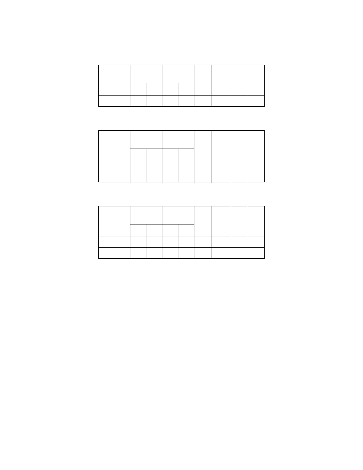
ELECTRICAL DATA
MODEL No.: PV036
POWER
SUPPLY
(V-Ph-Hz)
208/230-3-60 187 253 11.4 77 1.9 3.6 19.7 30
VOLTAGE
RANGE
MIN. MAX. RLA LRA
COMPRESSOR
*
FAN
MOTOR
FLA
*
BLOWER
MOTOR
FLA
MCA MOCP
MODEL No.: PV048
POWER
SUPPLY
(V-Ph-Hz)
208/230-3-60 187 253 16.4 91 2.1 4.6 27.2 40
380-3-60
(4 WIRE)
VOLTAGE
RANGE
MIN. MAX. RLA LRA
342 418 9.3 54 2.1 4.6 18.3 25
COMPRESSOR
*
FAN
MOTOR
FLA
*
BLOWER
MOTOR
FLA
MCA MOCP
MODEL No.: PV060
POWER
SUPPLY
(V-Ph-Hz)
208/230-3-60 187 253 20.7 139 2.1 4.6 32.6 50
380-3-60
(4 WIRE)
VOLTAGE
RANGE
MIN. MAX. RLA LRA
342 418 10.7 64 2.1 4.6 20 30
COMPRESSOR
*
FAN
MOTOR
FLA
*
BLOWER
MOTOR
FLA
MCA MOCP
LEGEND:
FLA – Full Load Amps
RLA – Rated Load Amps
LRA – Locked Rotor Amps
MOCP – Maximum Over Current Protection
MCA – Minimum Circuit Amps
* Single phase motors
8
Page 10

MAINTENANCE INSTRUCTIONS
CRANKCASE HEATER
The function of crankcase heater is to hold the compressor oil reservoir at higher temperature than the coldest part in the system.
• Power must be supplied to crankcase heater for a minimum of 12-hours prior to system start-up. If power is off for 6-hours or more,
crankcase heater must be energized for 12-hours before operating the system. Otherwise compressor damage may result.
• Periodic checking for proper operation or crankcase heater is highly recommended as follows:
a) Check continuity of the heater using multimeter device.
b) Check grounding of the heater by Megger device (to prevent electrical hazards).
c) Observe whether the heater is warming down the compressor near the oil sump.
CLEANING OF COILS & FILTERS
• Turn off the power supply.
• Take out access panel of evaporator coil.
• Remove the filter by sliding out.
• Protect electrical components and motors from water washing.
• Clean the coil by flushing water by pressure washer followed by compressed air from supply to return direction.
• Filter shall be cleaned every month, in some hygienic application it is recommended for replacement.
• Cleaning drain pan and trap is recommended once in three months to prevent bacteria growing under the coil.
9
Page 11
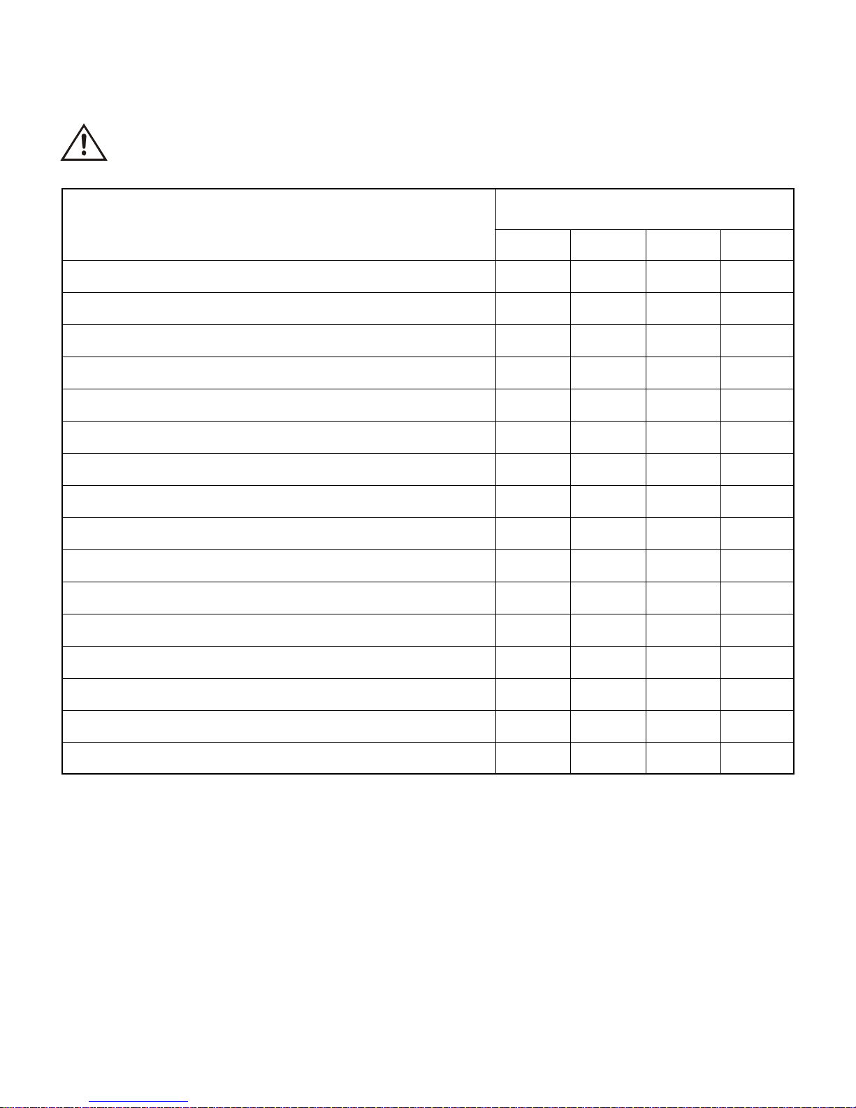
PREVENTIVE MAINTENANCE SCHEDULE
CAUTION: Disconnect power supply and allow all rotating parts to stop before servicing the unit.
I T E M
Clean air filters & replace if required.
Clean evaporator coil, drain pan & drain line.
Clean condenser coil.
Lubricate blower motor/condenser motor.
Check/clean electrical connections, controls & control box.
Check motors, fans and blower bearings & lubricate it.
Check all electrical control components, wiring terminals etc. for spark,
overheating & loose connections. Replace/correct as necessary.
Check insulation flanking. Repair/replace as required.
Check loose bolts/screws & tight as necessary.
Check for rusted/dented/damaged body parts & repair/repaint as necessary.
Check mountings/rubber pads. Repair/replace as necessary.
FREQUENCY OF MAINTENANCE, MONTHS
1
X
X
X
X
3
X
X
X
6
X
X
12
X
X
Run test all motors and check the amperage, abnormality etc.
Run test compressors and check the amperage, noise, oil level, pressure
etc. and correct them accordingly.
Check the thermostat/control devices for correct operation, calibrate/re- adjust as required.
Apply corrosion inhibitor/contact cleaner as required.
Check all pressures/temperatures as applicable and satisfy the operation & performance.
NOTE: Always observe for abnormal noise or vibration.
X
X
X
X
X
MAINTENANCE TOOLS/EQUIPMENT REQUIRED
STANDARD : Screw drivers (Slot & Phillips), adjustable wrenches, pliers, refrigeration wrenches & socket set wrenches, pulley
puller, etc.
SPECIAL : Manifold gauge set, R-22 charging cylinder, belt tension checker, leak detector, vacuum pump with electronic gauges,
thermometer & hook type ammeter/voltmeter/ohmmeter.
10
Page 12
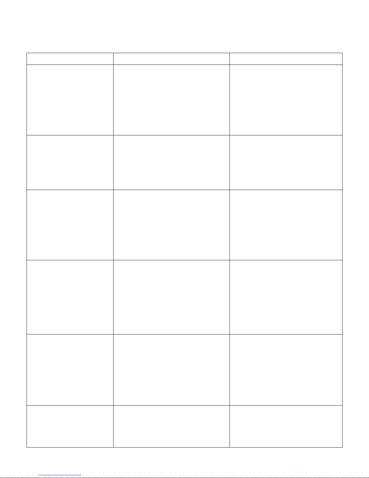
TROUBLE SHOOTING CHART
SYMPTOM CAUSES CHECK & CORRECTIVE MEASURE
Compressor will not start – no hum.
Compressor will not start – hums but
trips on overload protector.
1. Line disconnect switch open.
2. Fuse removed or blown.
3. Overload protector tripped.
4. Control stuck in open position.
5. Control off due to cold location.
6. Wiring improper or loose.
7. Thermostat defective or improperly installed.
8. Control circuit open.
9. Burned/open circuit motor winding.
1. Improperly wired.
2. Low voltage to unit.
3. Compressor motor has a winding open or
shorted.
4. Internal mechanical trouble in compressor.
5. Liquid refrigerant in compressor.
6. High discharge pressure.
1. Close start or disconnect switch.
2. Replace fuse.
3. Refer to electrical section.
4. Repair or replace control.
5. Relocate control.
6. Check wiring against diagram.
7. Replace or relocate.
8.
Trace control circuit with wiring diagram and repair.
9. Replace the compressor with all precautions.
1. Check wiring against diagram.
2. Determine reason and correct.
3. Replace compressor.
4. Replace compressor.
5. Check crankcase heater.
6. Unequalized pressure in the system.
Compressor starts and runs, but short
cycles on overload protector.
Units runs OK, but short cycles on. 1. Check the cause.
Unit operates long or continuously. 1. Shortage of refrigerant.
1. Additional current passing through overload protector.
2. Low voltage to unit (or unbalanced if three
phase).
3. Overload protector defective.
4. Excessive discharge pressure.
5. Suction pressure too high.
6. Compressor too hot - return gas hot.
7. Compressor motor has a winding shorted.
1. Overload protector.
2. Thermostat.
3. High pressure cut-out due to:
(a) Insufficient air.
(b) Overcharge.
(c) Air in system.
4. Low pressure cut-out due to:
(a) Undercharge.
(b) Restriction in expansion device.
2. Control contacts stuck or frozen closed.
3. Refrigerated or air conditioned space has excessive load or poor insulation.
4. System inadequate to handle load.
5. Evaporator coil iced.
6. Restriction in refrigeration system.
7. Dirty condenser.
8. Filter dirty.
1. Check wiring diagram. Check for added fan motors,
pumps, etc. connected to wrong side of protector.
2. Determine the reason and correct.
3. Check current, replace protector.
4. Check airflow across the condenser coil, restrictions in refrigeration system.
5. Check for possibility of misapplication. Use stronger unit.
6. Check refrigerant charge (fix leak), add if necessary.
7. Replace compressor.
2. Differential set too close - widen.
3. (a) Check airflow to the condenser - correct.
(b) Reduce refrigerant charge.
(c) Purge.
4. (a) Fix leak, add refrigerant.
(b) Replace device.
1. Fix leak, add charge.
2. Clean contacts or replace control.
3. Determine the fault and correct.
4. Replace with larger system.
5. Defrost.
6. Determine location and remove.
7. Clean condenser.
8. Clean or replace.
Suction line frosted or sweating. 1. Expansion valve passing excess refrigerant or
2. Expansion valve stuck open.
3. Evaporator fan not running.
4. Overcharge of refrigerant.
is oversized.
1. Re-adjust valve or replace with smaller valve.
2. Clean valve of foreign particles, replace if necessary.
3. Determine reason and correct.
4. Correct charge.
11
Page 13
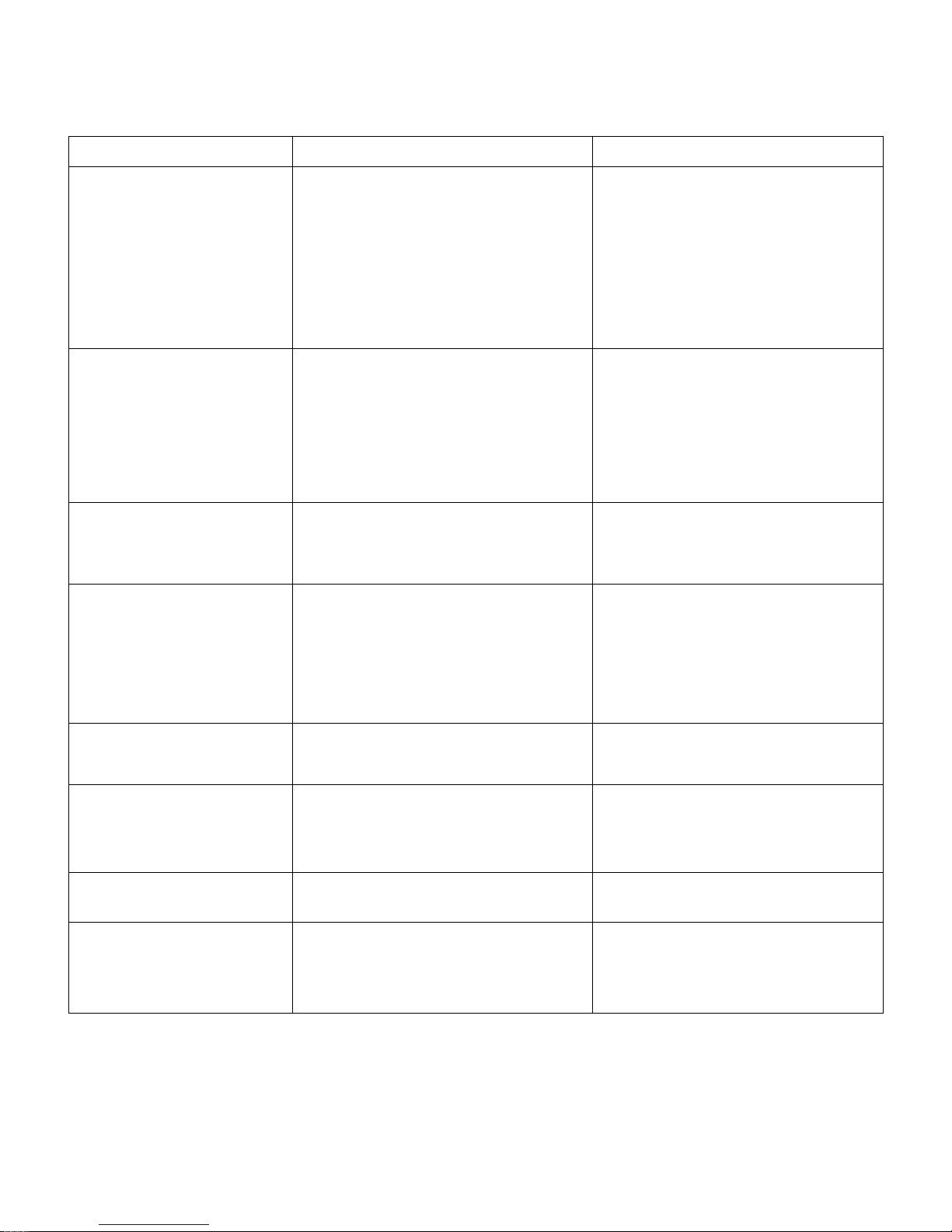
TROUBLE SHOOTING CHART
SYMPTOM CAUSES CHECK & CORRECTIVE MEASURE
Evaporator ices up.
1. Restricted airflow.
2. Dirty air filter.
3. Short of refrigerant.
4. Low air volume.
5. Restricted distributor tube.
6. Restricted liquid line/low liquid line pressure.
1. Check for dirt or lint on coil.
2. Clean or replace. Advice customer on periodic
cleaning of filter.
3. Check system pressure. Take superheat reading. Add refrigerant.
4. Check for dirty air filter or loose belt.
5. Check for warm distributor tube.
6. Check for restriction in lines/improve liquid line
pressure by proper charging or installing fan
cycle switch, etc.
Head pressure too high.
Head pressure too low. 1. Low ambient temperatures (air-cooled).
High suction pressure.
Run capacitor open, shorted or
blown.
Space temperature too high. 1. Control setting too high.
1. Refrigerant overcharge.
2. Air in system.
3. Dirty condenser.
4. Malfunction of condenser fan (air-cooled).
5. Excessive air temperature entering condenser.
6. Restriction in discharge line.
2. Refrigerant shortage.
3. Damaged valves in compressor.
1. High load on evaporator. Load in excess of design conditions.
2. Unbalanced system. Oversized air handling unit
matched with under sized condensing unit.
3. Compressor discharge valve leaking.
4. Expansion valve widely open.
5. Improper bulb location or installation.
1. Improper capacitor.
2. Excessively high line voltage (110% of rated
max.)
2. Expansion valve too small.
3. Cooling coils too small.
4. Inadequate air circulation.
1. Correct the refrigerant charge.
2. Recharge the system after a thorough triple
evacuation.
3. Clean.
4. Check and correct or replace.
5. Check for short circuiting of condenser discharge air, correct it.
6. Correct it.
1. Install fan cycling switch, if not provided. Check
the setting and operation, if provided.
2. Correct the refrigerant charge after leak testing.
3. Repair/replace the compressor.
1. Check the design.
2. Follow manufacturer's guide line and correct it.
3. Repair/replace compressor.
4. Check and adjust the superheat accordingly.
5. Check the expansion valve bulb is properly
tighten at correct location.
1. Determine correct size and replace.
2. Determine reason and correct.
1. Reset control.
2. Use larger valve.
3. Add surface or replace.
4. Improve air movement.
Liquid line frosted or sweating.
Unit noisy.
1. Restriction in dehydrator or strainer.
2. Liquid shut-off valve partially closed.
1. Loose parts or mountings.
2. Tubing rattle.
3. Bent fan blade causing vibration.
4. Fan motor bearings worn.
1. Replace part.
2. Open valve fully.
1. Find and tighten.
2. Tighten the pipe support.
3. Replace blade.
4. Replace motor.
12
Page 14
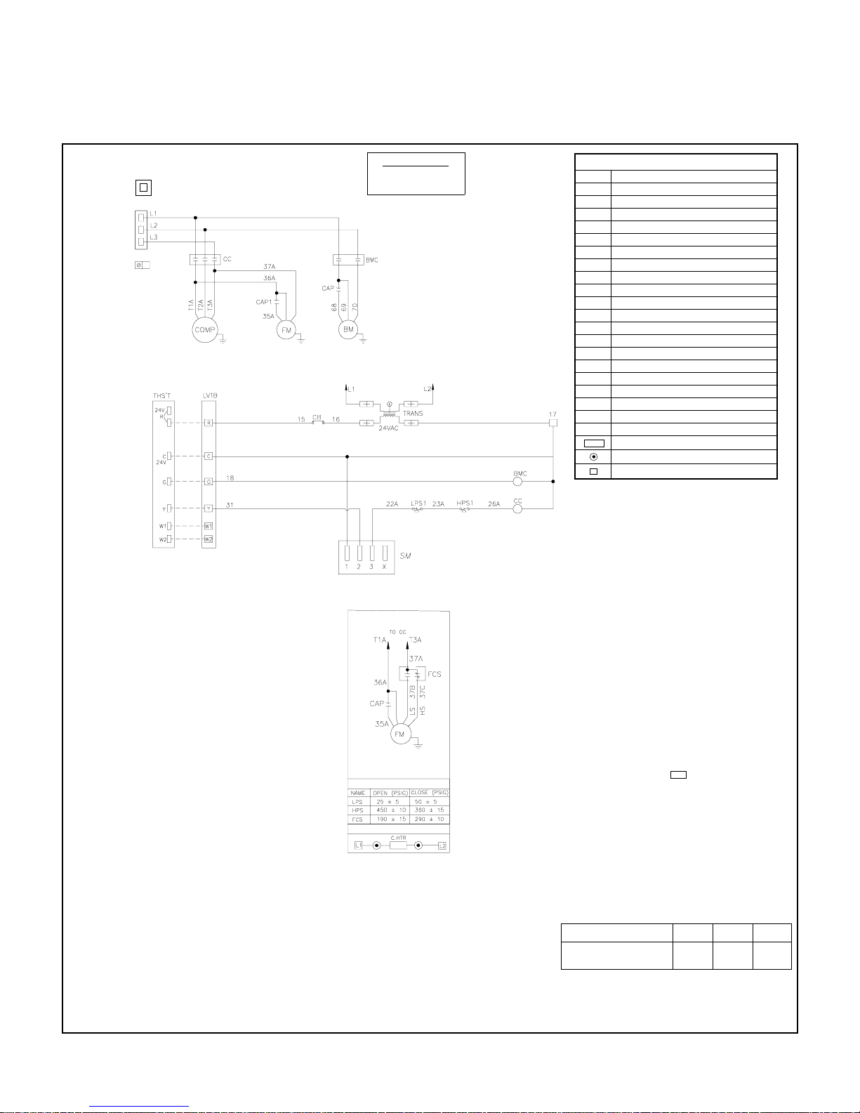
TYPICAL SCHEMATIC WIRING DIAGRAM
(For normal air-conditioning applications)
REFER TO UNIT
NAMEPLATE FOR
POWER SUPPLY
NTB
(SEE NOTE -11)
HVTB
LUG
WIRING DGM SUITS
230V/3PH/60HZ [&]
380V/3PH/60HZ UNIT
NOTE:
1. NTB IS APPLICABLE FOR 380V/3PH/60Hz UNITS
2. FOR UNITS WITH ABOVE VOLTAGE CONNECT 37A OF FM,
L2 OF BM & L2 OF TRANS TO NTB
LOW AMBIENT OPTION
SET POINTS
CRANKCASE HEATER CONNECTION
LEGEND
BM BLOWER MOTOR
BMC BLOWER MOTOR CONTACTOR
CAP CAPACITOR
CC COMPRESSOR CONTACTOR
CB CIRCUIT BREAKER
C. HTR CRANKCASE HEATER
COMP COMPRESSOR
FM FAN MOTOR (CONDENSER)
FCS FAN CYCLING SWITCH
HPS HIGH PRESSURE SWITCH
HVTB HIGH VOLTAGE TERMINAL BLOCK
LPS LOW PRESSURE SWITCH
LVTB LOW VOLTAGE TERMINAL BLOCK
L1 LINE 1
L2 LINE 2
L3 LINE 3
LUG LUG GROUND
NTB NEUTRAL TERMINAL BLOCK
SM SYSTEMIZER
TRANS TRANSFORMER
_ _ _
FIELD WIRING
+
DISCONNECT TAB
SPLICE-CLOSED END
TERMINAL BLOCK OR TERMINATION POINT
NOTES
1. POWER SUPPLY, REFER TO UNIT NAMEPLATE.
THERMOSTAT CONTROL VOLTAGE - 24VAC.
2. ANY WIRE REPLACEMENT SHOULD BE OF THE 900C
OR ITS EQUIVALENT.
USE COPPER CONDUCTOR WIRES ONLY.
3. POWER MUST BE SUPPLIED TO CRANKCASE HEATER FOR
MINIMUM OF 12 HOURS PRIOR TO SYSTEM START UP.
IF POWER IS OFF 6 HOURS OR MORE, CRANKCASE
HEATER MUST BE ON FOR 12 HOURS BEFORE OPERATING THE SYSTEM.
FAILURE TO FOLLOW THESE INSTRUCTIONS MAY RESULT IN COMPRESSOR DAMAGE.
4. A 3 TO 4 MINUTE (APPROX.) BUILT-IN SHORT CYCLE
PROTECTION FOR COMPRESSOR IS AVAILABLE IN
ZAMIL ELECTRONIC THERMOSTAT.
5. FUSED DISCONNECT SWITCH OR CIRCUIT BREAKER
TO BE PROVIDED BY CONSUMER WITH RATING AS
RECOMMENDED BY ZAMIL.
6. COMPRESSOR IS PROVIDED WITH INTERNAL OVERLOAD.
7. USE DISCONNECT TAB OR SPLICE ONLY WHERE
EVER REQUIRED FOR EXTENSION OF ORIGINAL WIRE.
8. FOR ANY SAFETY TRIP OF COMP. (FAULT), VOLTAGE
ACROSS TERMINAL 1 & X OF ECB (SYSTEMIZER) IS
24VAC. ALSO, COMPRESSOR LOCKOUT LIGHT IS ON.
9. FREE END OF MOTOR LEADS TO BE CAPPED WITH
CRIMPABLE WIRE NUT.
10.SM HAS 3 TO 5 MINUTES PROVISION FOR COMPRESSOR ANTI-RECYCLING TIMER.
11.NEUTRAL LINE REQUIRED ON 380V-3Ph-60Hz POWER
SUPPLY ONLY.
MODEL PV036 PV048 PV060
FACTORY INSTALLED
BM SPEED (WIRE COLOR)
+
BLK BLU BLK
13
Page 15
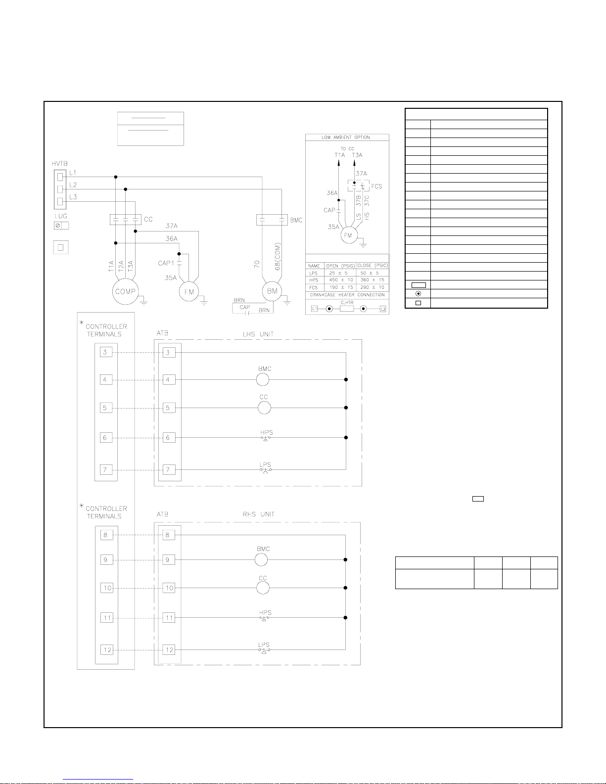
TYPICAL SCHEMATIC WIRING DIAGRAM
(For communication shelter applications)
NTB
POWER SUPPLY
PLS. REFER UNIT NAME PLATE
WIRING DG M SUITS
230V/3PH/60Hz
380V/3PH/60Hz
NOTE:
1. NTB IS APPLIC A BL E FOR 380V/3PH/60Hz UNITS
2. FOR UNITS WITH ABOVE VOLTAGE CONNECT 37A OF FM &
L2 OF BM TO NTB
SET POINTS
LEGEND
ATB AUXILIARY TERMINAL BLOCK
BM BLOWER MOTOR
BMC BLOWER MOTOR CONTACTOR
CC COMPRESSOR CONTACTOR
CAP CAPACITOR
C. HTR CRANKCASE HEATER
COMP COMPRESSOR
FM FAN MOTOR (CONDENSER)
FCS FAN CYCLING SWITCH
HPS HIGH PRESSURE SWITCH
HVTB HIGH VOLTAGE TERMINAL BLOCK
L1 LINE 1
L2 LINE 2
L3 LINE 3
LPS LOW PRESSURE SWITCH
LUG LUG GROUND
NTB NEUTRAL TERMINAL BLOCK
_ _ _
FIELD WIRING
+
DISCONNECT TAB
SPLICE-CLOSED END
TERMINAL BLOCK OR TERMINATION POINT
NOTES
1. POWER SUPPLY, REFER TO UNIT NAMEPLATE.
THERMOSTAT CONTROL VOLTAGE - 24VAC.
2. ANY WIRE REPLACEMENT SHOULD BE OF THE 900C
OR ITS EQUIVALENT.
USE COPPER CONDUCTOR WIRES ONLY.
3. POWER MUST BE SUPPLIED TO CRANKCASE HEATER FOR
MINIMUM OF 12 HOURS PRIOR TO SYSTEM START UP.
IF POWER IS OFF 6 HOURS OR MORE, CRANKCASE
HEATER MUST BE ON FOR 12 HOURS BEFORE OPERATING THE SYSTEM.
FAILURE TO FOLLOW THESE INSTRUCTIONS MAY RESULT IN COMPRESSOR DAMAGE.
4. FUSED DISCONNECT SWITCH OR CIRCUIT BREAKER
TO BE PROVIDED BY CONSUMER WITH RATING AS
RECOMMENDED BY ZAMIL.
5. COMPRESSOR IS PROVIDED WITH INTERNAL OVERLOAD.
6. USE DISCONNECT TAB OR SPLICE ONLY WHERE
EVER REQUIRED FOR EXTENSION OF ORIGINAL WIRE.
7. FREE END OF MOTOR LEADS TO BE CAPPED WITH
CRIMPABLE WIRE NUT.
8. NEUTRAL LINE REQUIRED ON 380V-3Ph-60Hz POWER
SUPPLY ONLY.
MODEL PV036 PV048 PV060
FACTORY INSTALLED
BM SPEED (WIRE COLOR)
+
BLK BLU BLK
* CONTROLLER SETUP IS FOR 2 UNITS.
14
Page 16
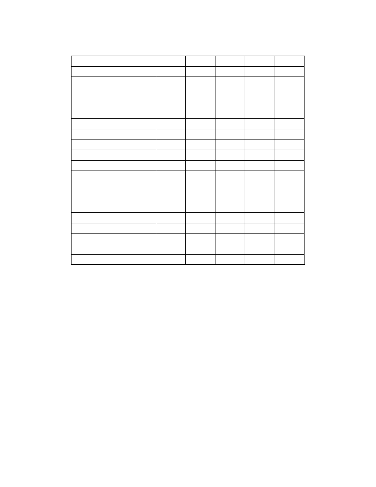
PARTS LIST
MODEL NUMBER PV036H PV048H PV048M PV060H PV060M
COMPRESSOR 800-674-26 800-674-20 800-674-21 800-674-13 800-674-14
CONDENSER FAN MOTOR 800-545-97 800-547-40 800-547-40 800-547-40 800-547-40
FAN MOTOR CAPACITOR 800-353-15 800-353-15 800-353-15 800-353-15 800-353-15
BLOWER MOTOR 800-547-52 800-555-29 800-555-29 800-555-29 800-555-29
BLOWER (SCROLL+WHEEL) 800-711-52* 800-089-63 800-089-63 800-089-63 800-089-63
CONDENSER FAN (PROPELLER) 800-941-41 800-225-01 800-225-01 800-225-01 800-225-01
CONDENSER FAN CYCLING SWITCH
CONTACTOR COMPRESSOR 800-095-00 800-097-00 800-095-00 800-097-00 800-095-00
CONTACTOR BLOWER MOTOR 800-736-01 800-736-01 800-736-01 800-736-01 800-736-01
TRANSFORMER (24V.) 800-012-30 800-012-30 800-012-30 800-012-30 800-012-30
EXPANSION VALVE 800-184-01 800-183-01 800-183-01 800-181-00 800-181-00
DISTRIBUTOR 800-198-01 800-198-02 800-198-02 800-198-02 800-198-02
LOW PRESSURE CONTROL 800-557-00 800-557-00 800-557-00 800-557-00 800-557-00
HIGH PRESSURE CONTROL 800-558-00 800-558-00 800-558-00 800-558-00 800-558-00
CONDENSER MOTOR MOUNT N.A. 800-154-15 800-154-15 800-154-15 800-154-15
FILTER DRIER 800-531-08 800-531-08 800-531-08 800-531-08 800-531-08
RETURN AIR PLEATED FILTER 800-240-58 800-240-51 800-240-51 800-240-51 800-240-51
SUPPLY AIR GRILLE 800-622-60 800-622-55 800-622-55 800-622-55 800-622-55
RETURN AIR GRILLE 800-622-87 800-622-83 800-622-83 800-622-83 800-622-83
N.A. 800-557-31 800-557-31 800-557-31 800-557-31
* BLOWER WHEEL ONLY
15
 Loading...