

YZ WM3-96 Technical data
Energy Management
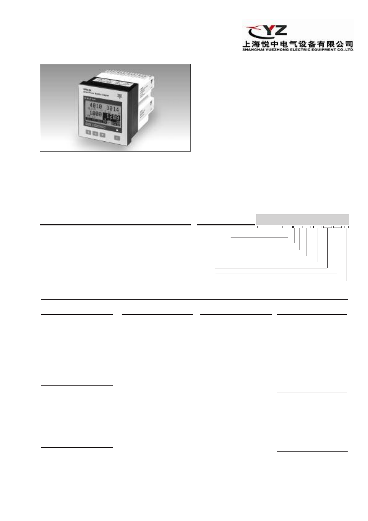
Modular Smart Power Quality Analyzer
Type WM3-96
• Class 0.5 (current/voltage)
2-bit µP-based modular smart power quality analyzer
• 3
• Graph display (128x64 dots)
• Front size: 96x96 mm
Measurements of single phase and system variables: W , Wdmd,
•
var , VA, VAdmd, PF, PFavg, V, A, An dmd (for all of them max. and
min. values). Energies: kWh and kvarh on 4 quadrants.
• Neutral current measurement
• TRMS measurement of distorted waves (voltage/current)
• Current and voltage inputs with autoranging capability
x4-dgt instantaneous variable read-out
• 4
• 4x9-dgt total energies read-out
• 4x6-dgt partial energies read-out
• 48 independent energy meters to be used as single,
dual, multi-time energy management
isplay refresh time: 100 msec @ 50 Hz
• D
• Harmonic distorsion analysis (FFT) up to 50th harmonic
with both graph and numerical indication (of current
and voltage)
• Harmonics source detection
• Optional RS232 + real time clock function with data
logging of alarm and MIN/MAX events, monthly energy
metering recording
• Degree of protection (front):IP 65
• Up to 4 optional alarm setpoints
• Up to 4 optional pulse outputs
• Up to 4 optional analogue outputs
• Optional serial RS 422/485 output
Universal power supply: 18 to 60VAC/DC - 90 to 260 VAC/DC
•
• MODBUS RTU, JBUS, (N2 MET ASYS protocols on r equest)
Product Description
32-bit µP-based smart power
quality analizer with a built-in
configuration key-pad.
The housing is for panel
mounting and ensures a
degree of protection (front) of
IP 65. The instrument is par-
Type Selection
Range code
240/415 VAC -
AV5:
1/5 AAC
(max. 300 V (L-N)/
520 V (L-L) - 6 A)
(standard)
AV7: 400/690VAC -
1/5 AAC
(max. 480V (L-N) /
830 V (L-L) / 6 A
System
3:
One phase, threephase system
(3 or 4 wires, balanced load)
Three phase system
(3 or 4 wires, unbalanced load)
Power supply
L:
18 to 60VAC/DC
H: 90 to 260VAC/DC
1)
On request
1)
1)
ticularly indicated for those
application where there is the
need to control the power
supply quality. The variables
being displayed are more
than 400.
Slot A (signal r
XX:
A1:
etransmission)
None
Single analogue output,
20mADC (standard)
A2:
Single analogue output,
5mADC
±
A3:
Single analogue output,
±10mADC
A4:
Single analogue output,
±20mADC
B1:
Dual analogue output,
1)
1)
1)
20mADC (standard)
B2: Dual analogue output,
±
5mADC
B3: Dual analogue output,
10mADC
±
B4: Dual analogue output,
20mADC
±
1)
1)
1)
V1: Single analogue output,
10VDC (standar
V2: Single analogue output,
±1VDC
V3: Single analogue output,
±5VDC
V4: Single analogue output,
10VDC
±
d)
1)
1)
1)
W1: Dual analogue output,
10VDC (standard)
W2: Dual analogue output,
±1VDC
W3: Dual analogue output,
±
W4: Dual analogue output,
±10VDC
5VDC
1)
1)
1)
Ordering Key
WM3-96AV53H XX XX XX XX X
Model
Range code
System
Power supply
Slot A
Slot B
Slot C
Slot D
Options
Slot B (signal r
XX:
B1:
etransmission)
None
Dual analogue output,
20mADC (standard)
B2: Dual analogue output,
±5mADC
B3: Dual analogue output,
10mADC
±
B4: Dual analogue output,
±20mADC
1)
1)
1)
W1: Dual analogue output,
10VDC (standard)
W2: Dual analogue output,
±1VDC
W3: Dual analogue output,
±5VDC
W4: Dual analogue output,
10VDC
±
1)
1)
1)
S1: Serial port,
RS485 multidr
bidirectional
1)
op,
NNoottee::
Slot A + Slot B
Max 4 analogue outputs
Slot C + Slot D
max 4 digital outputs
Slot C (alarm or pulse out)
XX:
None
R1:
Single relay output,
(AC1-8AAC, 250VAC)
R2: Dual relay output,
(AC1-8AAC, 250VAC)
O1:
Single open collector
1)
1)
output (30V/100mADC)
O2:
Dual open collector output (30V/100mADC)
D1:
3 digital inputs
1)
1)
Slot D (alarm or pulse out)
XX:
None
R2: Dual relay output,
(AC1-8AAC, 250V
O2:
Dual open collector out
put (30V/100mADC)
O4:
4 open collector out
puts (30V/100mADC)
AC)
1)
1)
1)
Options
X: None
S: Serial RS232 + RTC
N: With N2 Metasys protocol
C: options: S+N
1)
-
-
1

WM3-96
Input Specifications
umber of inputs
N
Current 2 (system: single phase)
6 (system: 3-phase)
Voltage 2 (system: single phase
4 (system: 3-phase)
Digital 3 free of voltage contacts
for Wdmd, VAdmd,
An dmd, PFavg synchronization
Reading voltage/current:
7.5 to 25VDC/<8mA
1
Accuracy
urrent (A
C
(displa y, RS232, RS4 8 5) In: 5A, If.s.: 6A, start-up I: 15mA
A
A
,
,
1
L
)
2
3
L
L
±0.5% RDG (0.2 to1.2 In)
±5mA (0.02 to 0.2 In)
Current (A
) ±1% RDG (0.2 to 1.2 In)
n
@ 40 to 100 Hz
Voltage AV5 range: ±0.5% RDG (48 to 300 V
±1% RDG (84 to 519 V
AV7 range: ±0.5% RDG (80 to 480 V
1% RDG (139 to 830 V
±
includes also:
frequency , power supply
and output load influences
Frequency ±0.1% RDG (40 to 440 Hz)
Active power
(@ 25°C ± 5°C, R.H. ≤ 60%) ±0.5% (RDG + FS) (PF 0.5 L/C,
0.1 to 1.2 In, AV5 range) or
±1% RDG (PF 0.5 L/C,
0.1 to 1.2 In, AV5 range)
Reactive power
(@ 25°C ± 5°C, R.H. ≤ 60%) ±0.5% (RDG + FS) (PF 0.5 L/C,
0.1 to 1.2 In, AV5 range) or
±1% RDG (PF 0.5 L/C,
0.1 to 1.2 In, AV5 range)
Apparent power
(@ 25°C ± 5°C, R.H. ≤ 60%) ±0.5% (RDG + FS)
(0.1 to 1.2 In, AV5 range) or
±1% RDG
(0.1 to 1.2 In, AV5 range)
gies
Ener
(@ 25°C ± 5°C, R.H. ≤ 60%) Active: class 1 according to
EN61036
Reactive: class 2 accor
to EN61268
Ib: 5A, Imax: 6A
0.1Ib: 500mA
Start up current: 20mA
Un: 240V (AV5), 400V (A V7)
Harmonic distorsion 1% FS (FS: 100%)
(@ 25°C ± 5°C, R.H. ≤ 60%) phase: ±2°; Imin: 0.1Arms;
Imax: 15Ap; Umin: 50Vrms;
Umax: 500Vp
Sampling frequency
6400 samples/s @ 50Hz
Additional errors
0.3%RDG, 60% to 90% R.H.
Humidity
≤
Input frequency ≤ 0.4%RDG, 62 to 400 Hz
L-N
)
L-L
L
L-L
ding
agnetic field ≤ 0.5%RDG, @ 400 A/m
M
Temperature drift
ampling rate
S
≤200ppm/°C
400 samples/s @ 50Hz
6
Display Graph LCD, 128x64pixel,
back-lighted. Selectable
read-out for the instantaneous variables: 4x4-dgt or
1
4x3
/2-dgt
otal Energies: 4x9-dgt;
T
artial: 4x6-dgt
P
Max. and min. indication Max. 9999 (999,999,999),
Min. -9999 (–999,999,999)
Measurements Current, voltage, power,
energy, harmonic distortion
)
)
-N
)
(see “Display pages” table).
TRMS measurement of a distorted wave (voltage/current).
Coupling type: Direct
Crest factor: ≤3
(max. 15Ap/500Vp (V L-N)
or 15Ap/800Vp (V L-N)
Ranges (impedances)
AV5 58/100 V (>500 kΩ) -
1 AAC (≤
0.3 VA)
58/100 V (>500 kΩ) 5 AAC (≤ 0.3 VA)
240/415 V (>500 kΩ) 1 AAC (≤ 0.3 VA)
240/415 V (>500 kΩ
5 AAC (≤ 0.3 VA)
AV7 100/170 V ((>500 kΩ)
1 AAC (≤ 0.3 VA)
100/170 V (>500 kΩ) 5 AAC (≤ 0.3 VA)
400/690 V (>500 k
1 AAC (≤ 0.3 VA)
400/690 V (>500 kΩ) 5 AAC (≤ 0.3 VA)
equency range
Fr
-load protection
Over
Continuous: voltage/current AV5: 300 V
40 to 440 Hz
AV7: 480 V
LN
LN
For 1 s
AV5 600 V
/1040 VLL/120A
LN
AV7 960 VLN/1660 VLL/120A
Keypad 4 keys:
”S” for enter programming
phase and password confirmation,
”UP” and “DOWN” for
value programming/function
selection, page scr
“F” for special functions
) -
) -
Ω
/520 VLL/6A
/830 VLL/6A
olling
Output Specifications
Analogue outputs (on r
Number of outputs Up to 4 (on request)
Accuracy ±0.2% FS
Range 0 to 20 mADC,
2
equest)
°C ±5°C, R.H. ≤60%)
(@ 25
0 to ±20 mADC
10 mADC,
±
0 to
0 to ±5 mADC
0 to 10 VDC,
10 VDC
±
0 to
5 VDC
±
0 to
0 to ±1 VDC

WM3-96
Output Specifications (cont.)
Scaling factor Programmable within the
hole r a n g e of retransmis-
w
ion; it allows the retrans-
s
mission management of all
values from:
0 to 20 mADC,
0 to ±20 mADC
0 to ±10 mADC,
0 to ±5 mADC
0 to 10 VDC,
0 to ±10 VDC
to ±5 VDC
0
0 to ±1 VDC
Variables to be retransmitted
All (see table“List of the variables
that can be connected to:”...)
Response time ≤ 200 ms typical
(filter excluded, FFT excluded
3 1/2 dgt indication)
Ripple
≤ 1% according to IEC 60688-1
and EN 60688-1
emperature drift 200 ppm/°C
T
Load: 20 mA output ≤ 600 Ω
±20 mA output ≤ 550 Ω
±10 mA output ≤ 1100 Ω
± 5 mA output ≤ 2200 Ω
10 V output ≥
10 kΩ
±10 V output ≥ 10 kΩ
± 5 V output ≥ 10 kΩ
± 1 V output ≥ 10 kΩ
Insulation By means of optocouplers,
4000V
output to
MS
R
measuring input
4000V
output to supply input
RMS
RS422/RS485 output
(on request) Multidrop
bidirectional (static and
dynamic variables)
Connections 4 wires, max. distance
1200m, termination directly
on the module
Addresses 1 to 255, selectable by key-pad
Protocol MODBUS RTU /JBUS,
(N2 METASYS on request)
Data (bidirectional)
Dynamic (r
eading only) All display variables (see also
the table, “List of the variables
that can be connected to”...)
Static (writing only)
All configuration parameters,
reset of energy, activation of
digital output
Stored energy (EEPROM)
max. 999.999.999 kWh/kvarh
Data format 1-start bit, 8-data bit, no
,
, 1 stop bit
Baud-rate
parity/even parity
odd parity
1200, 2400, 4800 and 9600
selectable bauds
Insulation By means of optocouplers,
4000 V
RMS
output to
measuring inputs
4000 V
output to
RMS
supply input
RS232 output (on r
equest)
ectional (static and
Bidir
dynamic variables)
Connections 3 wires, max. distance 15m,
Data format 1-start bit, 8-data bit,
no parity, 1-stop bit
Baud-rate 9600 bauds
Protocol MODBUS (JBUS)
Other data as for RS422/485
igital outputs (on request)
D
p to 4 outputs (combina-
U
tion of alarms and pulse
outputs)
The working of the outputs:
pulse or alarm or both of
them is fully programmable
and is independent from the
chosen output module.
puts remotely controlled by
the serial communication port
Pulse outputs (on request)
Number of outputs Up to 4, independent
Type
From 1 to 1000 programmable
pulses for K-M-G Wh, K-M-G varh,
open collector (NPN transistor)
1.2 VDC/ max. 100 mA
V
N
O
V
30 VDC max.
OFF
Outputs connectable to total
and partial energy meters
Pulse duration
220 ms (ON), ≥
220 ms (OFF)
According to DIN43864
Insulation By means of optocouplers,
4000 V
output to
rms
measuring input,
4000V
output to supply input.
rms
Note The outputs can be either
open collector type or relay
type (for this latter one see
the characteristics men-
tioned in the ALARMS).
Alarms outputs (on request)
Number of setpoints
Up to 4, independent
Alarm type Up alarm, down alarm, up
alarm with latch, down alarm
with latch, phase assymetry
phase loss, neutral loss
Variables to be controlled
All (see table“List of the variables
that can be connected to:”...)
Setpoint adjustment
Hysteresis
On-time delay
0 to 100% of the electrical scale
0 to 100% of the electrical scale
0 to 255 s
Relay status Selectable, Normally de-
energized, normally energized
Output type Relay
, SPDT
AC 1-8A, 250VAC
DC 12-5A, 24VDC
AC 15-2.5A, 250VAC
DC 13-2.5A, 24VDC
Min. response time ≤ 150 ms, filter excluded,
FFT excluded,
setpoint on-time delay: ”0s”
Insulation 4000 V
RMS
output to
measuring input,
4000V
output to supply input
RMS
Note The outputs can be either
relay type or open collector
type (for this latter one, see
the characteristics mentio-
in the PULSE OUTPUTS).
ned
Out-
,
3

WM3-96
Software Functions
Password Numeric code of max. 3 di-
1st level Password “0”, no protection
nd level Password from 1 to 499, all
2
Transformer ratio For CT up to 30000 A,
Scaling factor
Operating mode Electrical scale: compression/
Electrical range Programmable within the
Filter
Filter operating range 0 to 99.9% of the
Filtering coefficient 1 to 255
gits; 2 protection levels of
the programming data
ata are protected
d
For VT up to 600 kV
expansion of the input scale
to be connected to up to 4
analogue outputs.
whole measuring range
input electrical scale
Supply Specifications
Filter action Display, alarm, analogue
Event logging Only with RS232 + RTC
age Variables
P
Display language English, Italian, French, Ger-
and serial outputs
(fundamental variable s:
, A, W and their derived ones)
V
module. The alarms max/min
alues will be stored with
v
ime (hh:mm:ss) and date
t
dd:mm:yy) references
(
Max. capacity: 480 events
ax. 4/page, one freely prog.
M
page + 26 variable pages +
ing to the kind of
d
accor
period selection: up to 12
energy meter pages.
man, Spanish
AC/DC voltage 90 to 260VAC/DC (standard),
18 to 60VAC/DC (on request),
General Specifications
Operating temperatur
Storage temperatur
Insulation reference voltage 300 V
Insulation 4000 V
Dielectric strength 4000 V
Noise rejection
CMRR 100 dB, 48 to 62 Hz
EMC EN 50081-2, EN 50082-2
Other standards
Safety requirements: IEC 61010-1, EN 61010-1
Product requirements: IEC 60688-1, EN 60688-1
e
e
0 to +50
(R.H. < 90% non-condensing)
-10 to +60
(R.H. < 90% non-condensing)
outputs to gr
C (32 to 122°F)
°
14 to 140
C (
°
to ground (AV5 input)
RMS
betweenall inputs/
RMS
ound
for 1 minute
RMS
F)
°
Power consumption ≤30VA/12W (90to 260V)
equirements Energy measurements:
oduct r
Pr
Pulse output:
ovals
Appr
Connector Scr ew-type,
Housing
Dimensions 96x96x140 mm
Material
Degree of protection Front: IP65, NEMA4x, NEMA12
Weight Approx. 600 g
20VA/12W (18 to 60V)
≤
EN61036, EN61268.
DIN43864
CE,
UL, CSA
max. 2.5 mm2wir
ABS,
self-extinguishing: UL 94 V-0
(packing included)
es x 2
4
 Loading...