

Page 1

Yuneec™
SMARTRADIO™
ST24™ Quick Start Guide
Page 2

Features
Transmitter and Ground Station – All in One
The ST24 is not only an advanced 24-channel RC transmitter – it’s also a powerful
Personal Ground Station (PGS) that includes built-in hardware and functionality for
First-Person View (FPV), a flight simulator and an Android™ tablet/pad. With the
convenient and portable ST24 it’s no longer necessary to use separate components to
view and even record real-time video during flight.
Improved Radio Diversity and Range
Dual 2.4GHz antennas are installed in the ST24 to improve radio transmission diversity
and range. The result is a more reliable radio link with range that exceeds typical line of
sight operations.
Two-Way Communication With Telemetry
The ST24 not only transmits control information, it also downloads vital aircraft status
information. During flight the pilot can see telemetry data including real-time battery
voltage, signal strength, aircraft altitude, airspeed, distance from home and more right on
the screen.
Extended-Range Video Downlink
The built-in 5.8GHz video downlink makes it possible to view real-time video on the
ST24’s 7” LCD screen. And when used in conjunction with the Yuneec C-GO1 camera or
other Flying Eyes downlink transmitters, range can be up to 2,600 feet (800 meters) or
more.
Universal Channel Control System
The Universal Channel Control System offers an innovative and revolutionary way to view,
set and adjust every channel. From input devices and hardware to output channels and
functions, every setting and adjustment including reversing, dual rates, mixing and more is
found in a single menu. No longer do you need to struggle with cumbersome sub-menus
or difficult to understand abbreviations – the ST24 makes it easier to see and customize
more channel settings than any transmitter before.
Built-In Flight Simulator
You can use the built-in Android™ app based flight simulator to enjoy the convenience
and benefit of learning or practicing to fly using the same transmitter and controls you’ll
actually be flying with.
Built-in Android™ Tablet/Pad
The built-in Android tablet/p ad makes it possible to listen to music, watch videos, run app s
and more. And when you’re connected to WiFi you can even check email, surf the web
and upload your latest photos and videos without the need for a separate device. This
2
Page 3

means you have more functionality, flexibility and convenience packed into your very own
Personal Ground Station (PGS).
3
Page 4

IMPORTANT NOTE: This Quick Start Guide is NOT intended to replace
the complete content included in the ST24 instruction manual. Although
the following information covers some of the basic details you need to
know we strongly recommend reading through the instruction manual
completely before charging/using the ST24.
Charging Your ST24
Use a suitable power source/supply (1.5A and 5V MAX output) and a cable with a Micro
USB connector to charge the 3.7V Li-Ion battery installed in the ST24. The time it takes to
fully charge the battery will depend on the current voltage/charge state of the battery and
the charge rate of your chosen power source/supply. For reference it will typically take
approximately 6 hours to charge a near fully discharged battery at the maximum
recommended charge rate of 1.5 amps.
1. Connect the cable with the Micro USB connector to the suitable power
source/supply
2. Connect the Micro USB connector to the corresponding port on the bottom of the
ST24
3. When the transmitter is turned on the battery icon located in the upper right-hand
corner of the screen (in select menus) will show a ‘plug’ inside while the battery is
charging
You can also remove the battery from the back of the ST24 and charge it separately using
a suitable Li-Ion battery charger and a lead with a compatible 2-pin JST connector (at a
maximum recommended charge rate of 1.5 amps).
IMPORTANT NOTE: Charging the Li-Ion battery using an incompatible charger
(such as a NiCd or NiMH battery charger), or even a compatible battery charger with
the incorrect settings, may result in damage to the battery or even fire resulting in
property damage and/or personal injury.
Using Your ST24
In the Radio Control (RC) Mode
For RC-only (non-FPV/camera-equipped) models
1. Power on the ST24 and enter RC mode
Slide the Power Switch to the left to power on the ST24
NOTE: The switch does not extend beyond the surface of the transmitter to
4
Page 5
minimize the risk of accidentally powering the transmitter off during use
Tap the RC button/icon
Power Switch
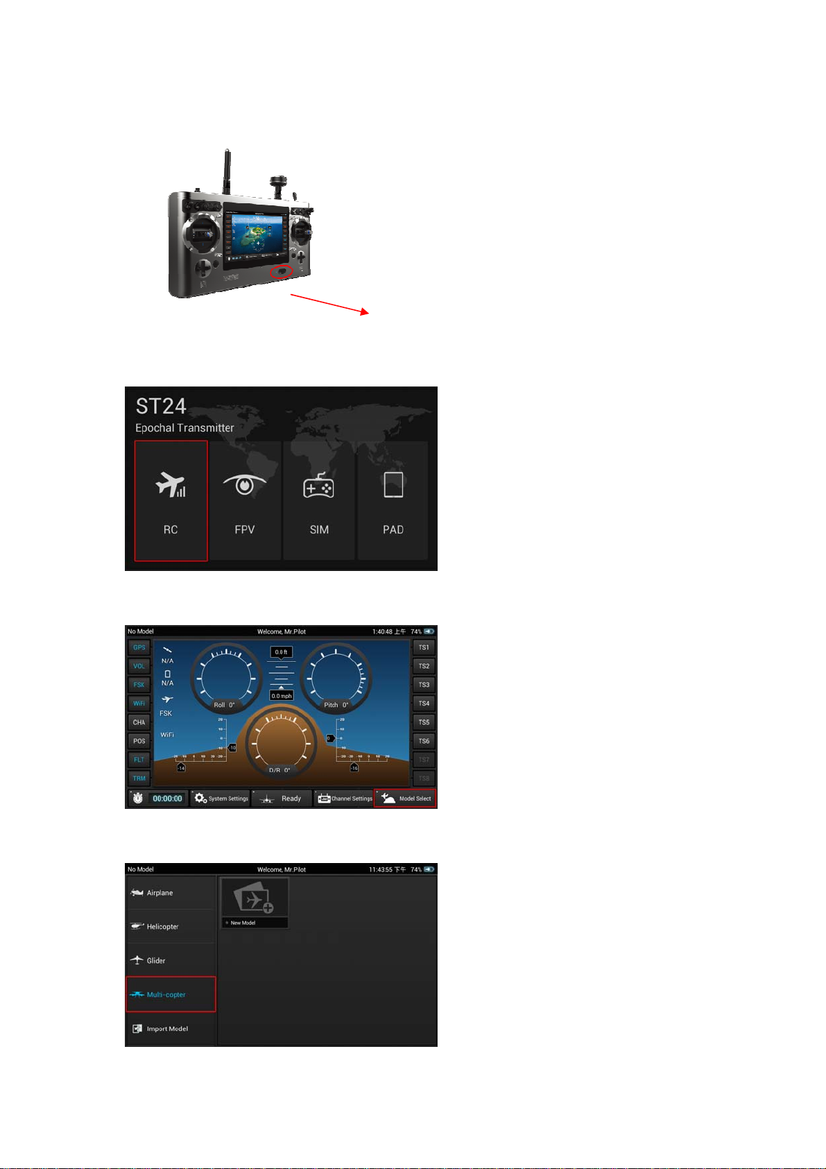
Tap the Model Select button/icon
Select the type of model (Multi-copter, Airplane, etc.) you’d like to create or load
5
Page 6
Select an existing model or create a New Model
To create a new model tap the New Model button/icon
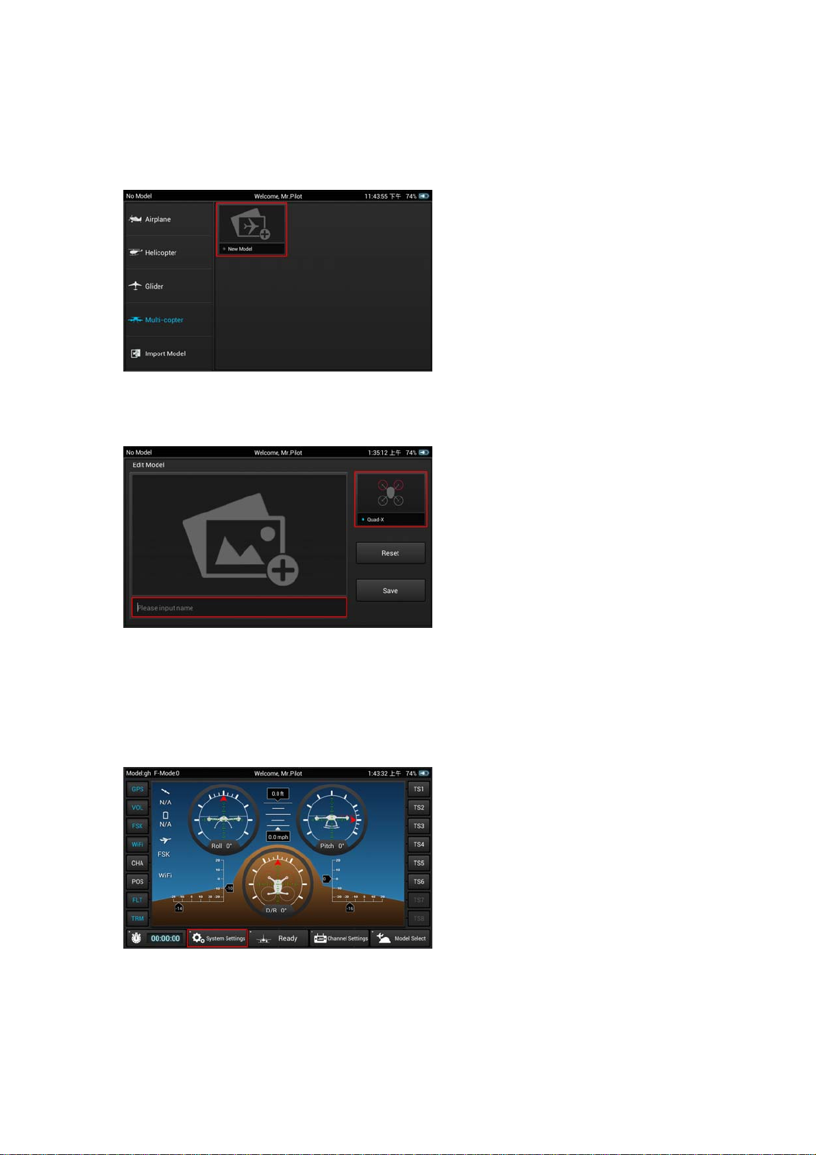
Give the new model a name, take or select an image (optional), select a type (if
applicable) then Save the new model
2. Bind the ST24 to your receiver/model
Follow the instructions included with your receiver/model to enter the bind mode
Tap the System Settings button/icon
6
Page 7

Tap the Refresh button/icon
Select the corresponding ID of the receiver/model
Tap the Bind button/icon
The receiver/model should now be bound to the ST24. Or, if the receiver/model
was not bound successfully repeat the steps outlined above to complete the
binding process.
3. Define the channels
Return to the main RC Mode screen (tap the ’Back’ or ‘Home’ icons located near
the bottom of the screen as needed)
7
Page 8

Tap the Channel Settings button/icon
NOTE: If the ST24 did not recognize the receiver/model and automatically identify
the number and type of channels a corresponding menu will pop-up and you will
be prompted to set the number of analog and switch channels accordingly
Select the output channel/function (Thr, A01, etc) you’d like to view
If you prefer to change the default input device/hardware (J1, K2, S3, etc.) set to
control the selected output channel/function, tap the corresponding input
device/hardware button then tap Deactivate and proceed to the following steps
Select the new input device/hardware to control the selected output
channel/function by tapping the desired input device/hardware button, then tap
Edit to adjust the corresponding details (reverse, travel adjustment/rate, speed,
etc.)
NOTE: You can set Priority, Edit, Deactivate or view the Properties of each channel.
8
Page 9
You can also define which switch controls the Flight Mode.
There are multiple levels of mixing priorities. The highest level input
device/hardware will be processed first.
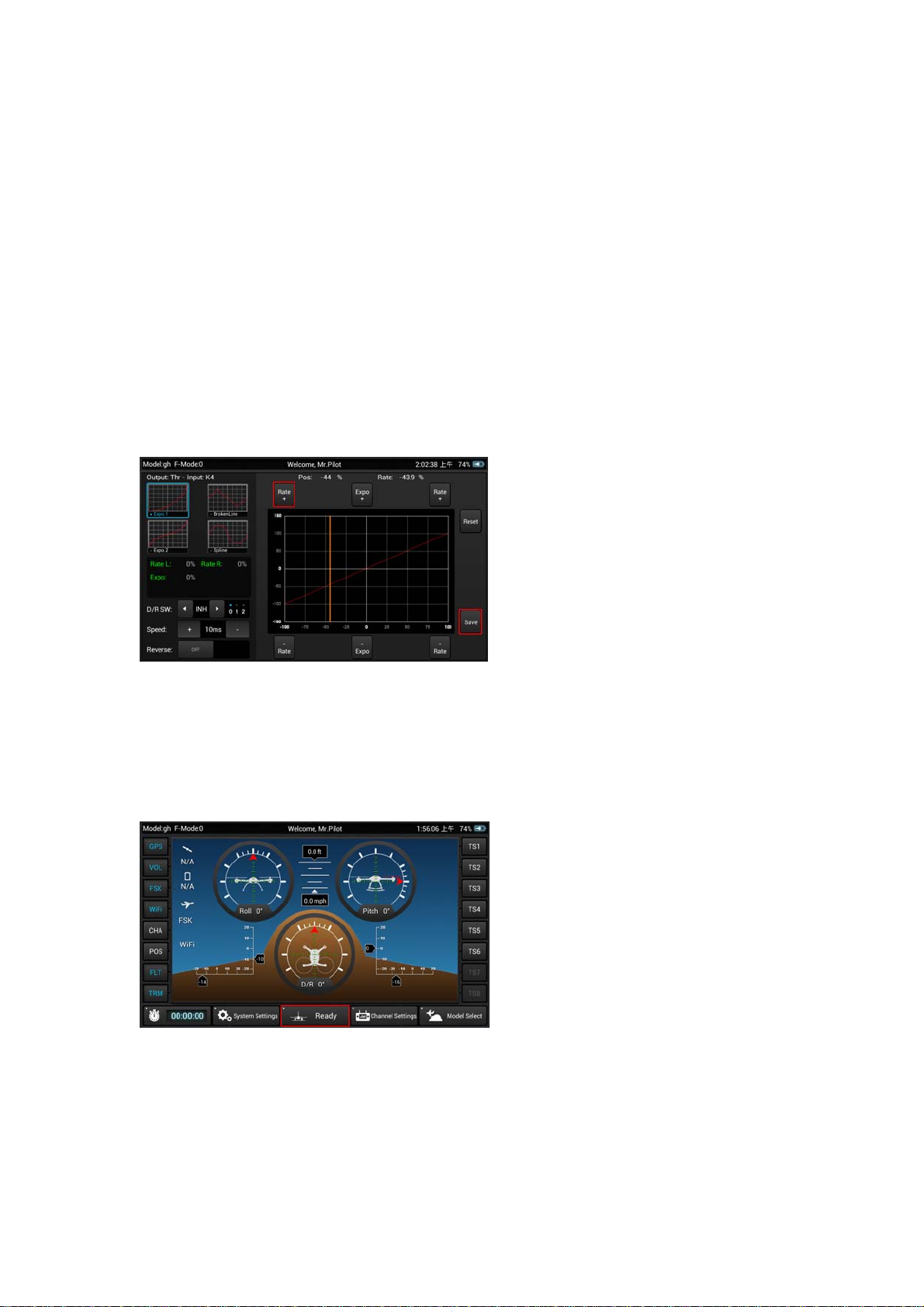
There a re m ultiple types of basic expo and control curves that can be selected fo r
each output channel/function. If you want to adjust any curve you can use the
buttons above and below the graph or you can touch the curve on the graph
directly.
Reverse, Dual Rate (D/R) and even output Speed can be changed as
needed/preferred.
After making any changes you MUST tap the Save button to save them.
Return to the main RC Mode screen (tap the ’Back’ or ‘Home’ icons located near
the bottom of the screen as needed)
Tap the Ready button/icon when you are ready to fly
9
Page 10

Using Your ST24
In the First-Person View (FPV) Mode
For FPV/camera-equipped models
1. Power on the ST24 and enter RC mode
Slide the Power Switch to the left to power on the ST24
NOTE: The switch does not extend beyond the surface of the transmitter to
minimize the risk of accidentally powering the transmitter off during use
Tap the FPV button/icon
Tap the Model Select button/icon
Power Switch
10
Page 11

Select the type of model (Multi-copter, Airplane, etc.) you’d like to create or load
Select an existing model or create a New Model
To create a new model tap the New Model button/icon
Give the new model a name, take or select an image (optional), select a type (if
applicable) then Save the new model
2. Bind the ST24 to your receiver/model
Follow the instructions included with your receiver/model to enter the bind mode
11
Page 12

Tap the System Settings button/icon
Tap the FPV button/icon then press the Refresh button/icon
Select the corresponding ID of the receiver/model
12
Page 13

Select the corresponding ID of the camera and/or downlink transmitter associated
with your aircraft
NOTE: Follow the instructions included with your camera and/or downlink
transmitter if needed to ensure they’re already bound to or that they can be bound
to the ST24
Tap the Bind button/icon
The receiver/model should now be bound to the ST24. Or, if the receiver/model
was not bound successfully repeat the steps outlined above to complete the
binding process.
3. Define the channels
Return to the main FPV Mode screen (tap the ’Back’ or ‘Home’ icons located near
the bottom of the screen as needed)
13
Page 14

Tap the Channel Settings button/icon
NOTE: If the ST24 did not recognize the receiver/model and automatically identify
the number and type of channels a corresponding menu will pop-up and you will
be prompted to set the number of analog and switch channels accordingly
Select the output channel/function (Thr, A01, etc) you’d like to view
If you prefer to change the default input device/hardware (J1, K2, S3, etc.) set to
control the selected output channel/function, tap the corresponding input
device/hardware button then tap Deactivate and proceed to the following steps
Select the new input device/hardware to control the selected output
channel/function by tapping the desired input device/hardware button, then tap
Edit to adjust the corresponding details (reverse, travel adjustment/rate, speed,
etc.)
14
Page 15

NOTE: You can set Priority, Edit, Deactivate or view the Properties of each channel.
You can also define which switch controls the Flight Mode.
There are multiple levels of mixing priorities. The highest level input
device/hardware will be processed first.
There a re m ultiple types of basic expo and control curves that can be selected fo r
each output channel/function. If you want to adjust any curve you can use the
buttons above and below the graph or you can touch the curve on the graph
directly.
Reverse, Dual Rate (D/R) and even output Speed can be changed as
needed/preferred.
After making any changes you MUST tap the Save button to save them.
Return to the main FPV Mode screen (tap the ’Back’ or ‘Home’ icons located near
the bottom of the screen as needed)
Tap the Take Off button/icon when you are ready to fly
15
Page 16

Using Your ST24
In the Simulator (SIM) Mode
Power on the ST24 and enter SIM mode
Slide the Power Switch to the left to power on the ST24
Power Switch
Tap the SIM button/icon
Follow the on-screen instructions
Using Your ST24
In the Tablet/Pad (PAD) Mode
Power on the ST24 and enter PAD mode
Slide the Power Switch to the left to power on the ST24
Power Switch
16
Page 17

Tap the PAD button/icon
Use the LCD screen as a typical Android™ tablet/pad
©2014
FCC STATEMENT
1. This device complies with Part 15 of the FCC Rules. Operation is subject to the following two
conditions:
(1) This device may not cause harmful interference.
(2) This device must accept any interference received, including interference that may cause
undesired operation.
2. Changes or modifications not expressly approved by the party responsible for compliance could
void the user's authority to operate the equipment.
NOTE: This equipment has been tested and found to comply with the limits for a Class B digital
device, pursuant to Part 15 of the FCC Rules. These limits are designed to provide reasonable
protection against harmful interference in a residential installation.
This equipment generates uses and can radiate radio frequency energy and, if not installed and
used in accordance with the instructions, may cause harmful interference to radio communications.
However, there is no guarantee that interference will not occur in a particular installation. If this
equipment does cause harmful interference to radio or television reception, which can be
determined by turning the equipment off and on, the user is encouraged to try to correct the
interference by one or more of the following measures:
Reorient or relocate the receiving antenna.
Increase the separation between the equipment and receiver.
Connect the equipment into an outlet on a circuit different from that to which the receiver is
connected.
Consult the dealer or an experienced radio/TV technician for help.
RF warning statement:
The device has been evaluated to meet general RF exposure requirement. The device can be used
in portable exposure condition without restriction.
17
 Loading...