

Page 1
Page 1 of 12 Mezzo Hanging Patio Heater 29/10/10
MEZZO
Hanging Patio Heater
August 2010
OPERATIONS, MAINTENANCE &
WARRANTY INFORMATION
www.yunca.co.nz
Page 2

Page 2 of 12 Mezzo Hanging Patio Heater 29/10/10
CONTENTS
Introduction Pg. 2
Installation Pg. 3
Operating Instructions Pg. 7
Servicing Pg. 7
Trouble Shooting Pg. 9
Warranty Information Pg. 10
Packing Parts Pg. 11
Warranty Registration Pg. 12
INTRODUCTION
Congratulations on purchasing your YUNCA MEZZO HANGING PATIO HEATER.
CAUTION: This unit must be installed so as it is not exposed to moisture.
This unit is designed to be mounted to a ceiling and out of the rain. The
operation is controlled by electronic 24 volt Microprocessor based direct spark
ignition control. The heater is started by turning on a switch.
WARNING: The Gas supply shall be fitted and commissioned by a registered Gas Fitter.
WARNING: The Electrical wiring shall be completed by an Qualified Electrician to
applicable Local Body and/or National standards.
WARNING: The controller uses voltages of shock hazard potential.
WARNING: Only authorised service technicians should undertake any repairs or
maintenance on this product.
It is recommended that the Heater has an annual maintenance check to ensure
its long term correct operation.
WARNING: Do not store or use aerosols or other flammable materials near this
appliance.
WARNING: The Yunca MEZZO Hanging Patio Heater is an unflued gas appliance
so adequate ventilation must always be provided to ensure safe and efficient use.
Each Yunca MEZZO Hanging Patio Heater is factory set to the appropriate operating
pressure for the gas type. Operating pressure is adjusted at either the LPG or NG in
line regulator.
This instruction booklet should stay with the appliance, and is for the reference of the
user and service person.
Please fill out and return the warranty registration card promptly (back page).
Page 3
Page 3 of 12 Mezzo Hanging Patio Heater 29/10/10
INSTALLATION
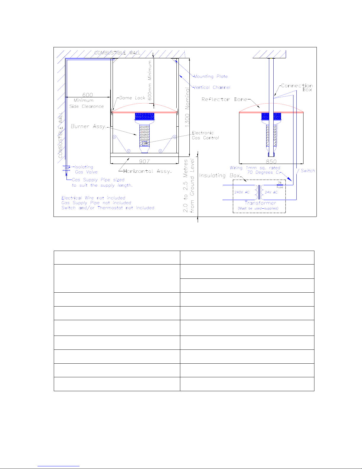
Fig 1
Features Specifications
Large Aluminum Parabolic, 2mm Reflective
Dome
Electronic Ignition – Microprocessor
Based Direct Spark Ignition Control
Gas Types: LPG and NG
Custom prepurge and interpurge timings Pressures: 2.75Kpa LPG, 1.0Kpa NG
Multiple tries Main Jet Sizes: 1.7mm(LPG); 2.8mm(NG)
Easily Assembled
Main Burner Worgas Stainless Steel,
Atmospheric.
System Diagnostic LED
Input Power: 18-30 VAC
Flame sense test pins Gas Valve: 2.0A @ 24VAC
Stainless Heater assembly
0.7µA Maximum
Powder coated Frame Flame Failure Response Time: 0.8 sec.
Page 4
Page 4 of 12 Mezzo Hanging Patio Heater 29/10/10
Selection of Position
WARNING: Yunca MEZZO Hanging Patio Heater is an unflued appliance, adequate
ventilation must always be provided. The Hanging Patio Heater has to be securely mounted
to a suitable beam or stand and be mounted away from the rain or any other moisture.
The heater should only be used when wind speeds are below 8km/h when heater is turned
down, or 16km/h when heater is on full.
The heater will effectively heat a radius of around 3m so its position should be chosen to
allow efficient use of heat.
Unpack and check that all parts are included. Refer to Table 1.
The following parts are NOT supplied:
M8 Bolts (x8) for attaching Mounting Plates to support
M8 Washers (x8) for attaching Mounting Plates to support
M8 Nuts (x8) for attaching Mounting Plates to support
Gas Pipe and fittings
Wire and fittings for the 240 volt supply
1mm Sq. wiring and fittings from the Transformer to the connection box at the vertical
channel. (24 volt side). Maximum length of 50 metres.
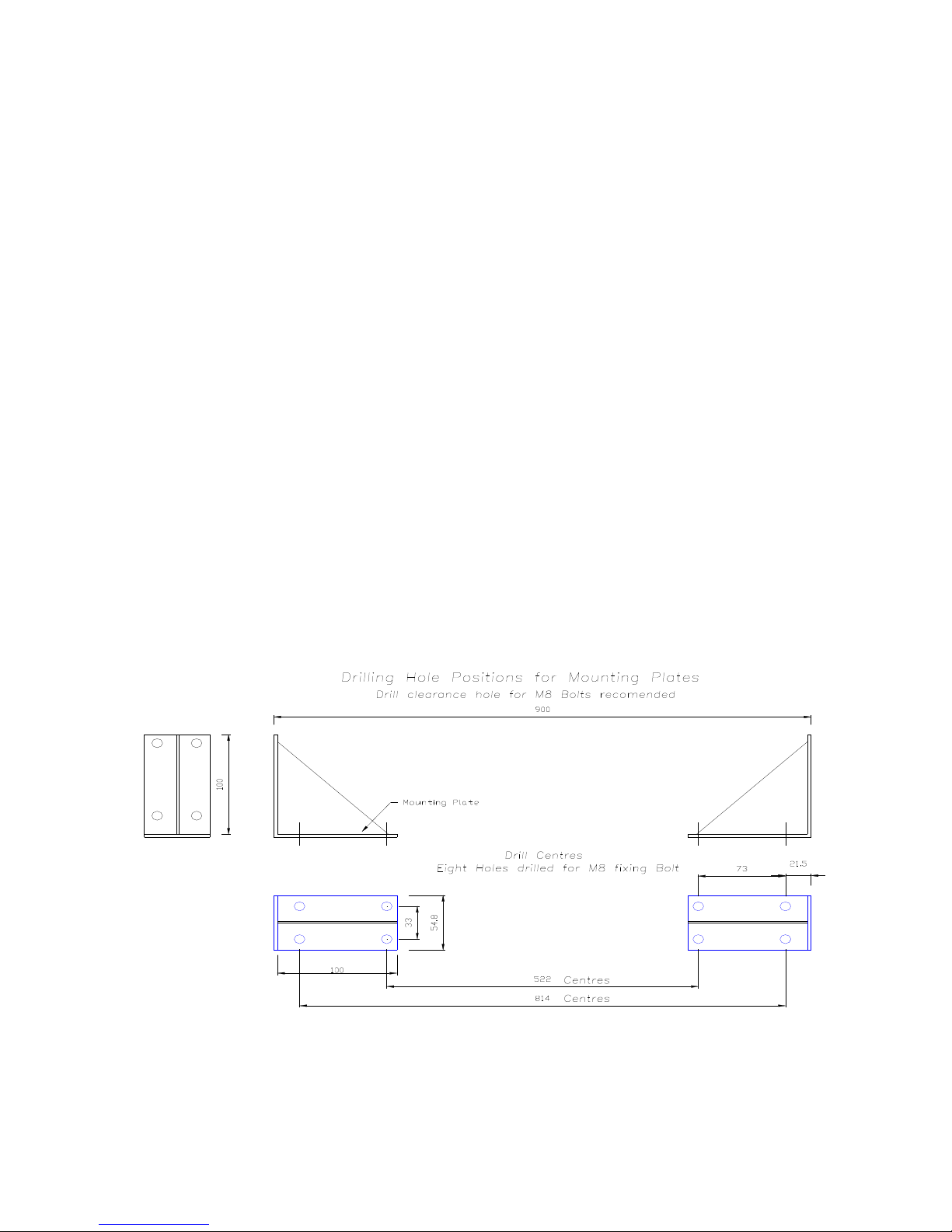
Bolting Holes:
Selection of the position to support the Yunca MEZZO Hanging Patio that offers a solid
base to bolt the Mounting plates too and be ideally 3.3 to 3.8 metres from the ground.
It is recommended to bolt the mounting plate in to position.
Mark out and drill suitable clearance holes for M8 Bolts. See Fig 2
Fig 2
Attach Mounting Plate: Bolt Mounting plates in to place as shown in Fig 2
Page 5
Page 5 of 12 Mezzo Hanging Patio Heater 29/10/10
Attach Channels:
Attach Vertical Channels to the Horizontal Assembly with M6 Bolts ensuring the channel
with the cable tie is bolted to the Arm with the cable tie.
Gas Piping.
Remove the two bolts from the holder clamp. Place the Burner assembly in to holder of
Horizontal Assembly. Make and Bend up the gas pipe to neatly fit in to the channel.
Remove the Burner assembly and gas pipe.
Make the gas joint.
Bolt Assembly in to place:
Bolt Horizontal Assembly with Vertical Arms on to the Mounting Plates. Care is required to
not damage the vertical arms with the assembly hanging from one side only during this
process.
Electrical supply:
WARNING: The controller uses voltages of shock hazard potential.
The Insulating box is supplied with Transformer mounted inside with a 2A fuse in a fuse
carrier.
The Insulating Box shall be positioned to allow future maintenance and access. Care is
required in removing the cut outs for the wire
Install the electrical wiring for the 240V supply to transformer and 24Volt system from the
24 volt side of the transformer to where the Connect Box will be mounted, positioning the
control switch and/or thermostat in required position.
24 Volt system, maximum length 50 metres (@ 1sq. mm).
Position Burner Assembly:
Position the burner assembly with Gas Pipe attached in to the Holder. Bolting tight with the
two bolts ensuring it is vertically positioned.
Electrical Connection:
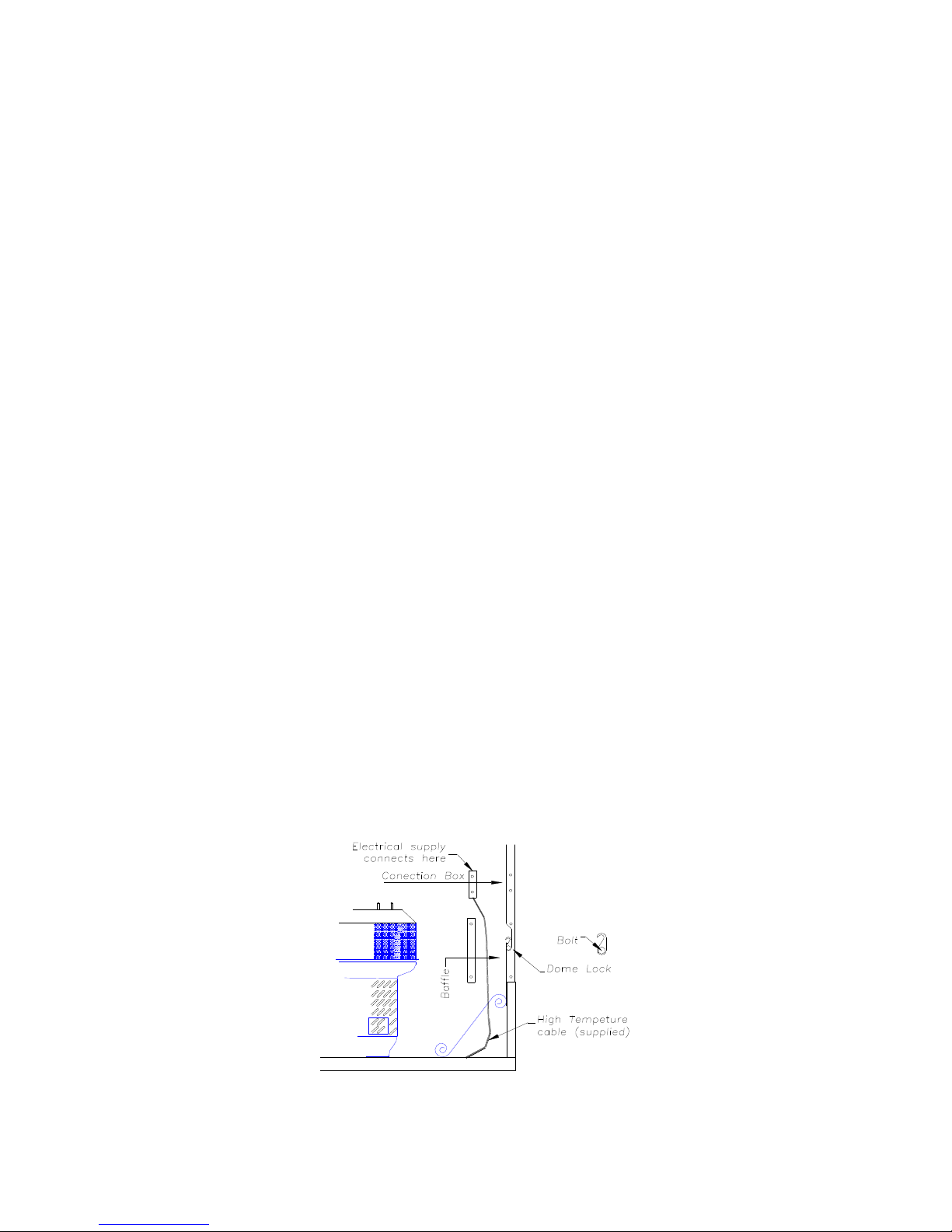
Make the 24 volt supply connection within the connection box, position the grommet into
place. (Fig 3). Remove the Baffle from the vertical Channel where the cord will go.
Position the Connection Box in to the vertical channel and screw in place.
Run the cable down from the connection box ensuring the cable is held close to the
channel, using the cable ties to hold in place.
Replace the baffle and screw in place ensuring the cable is not touching the
baffle.
Fig 3
Page 6
Page 6 of 12 Mezzo Hanging Patio Heater 29/10/10
Gas Connection:
A Gas Isolating valve must be positioned so it can be readily operated in an emergency. All
joints must be checked for leaks
Dome Fitting:
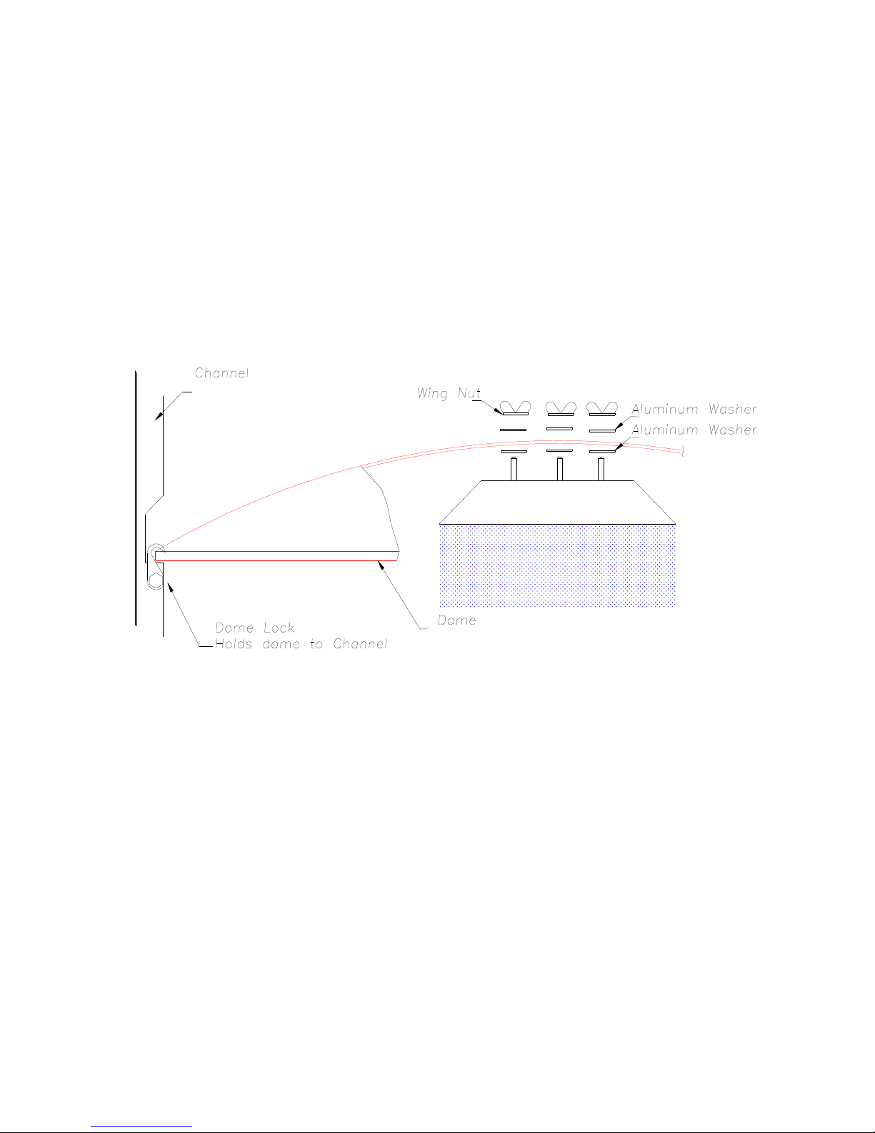
Remove the Dome Locks by unscrewing the bolts. Place one of the aluminium washers on
each of the studs. (Fig 4).
Position the Aluminium Reflective Dome between the vertical channels while aligning the
studs with the holes. Place the second washer on, followed by the wing nut and tighten
firmly.
Check the Burner is vertical, Position the four dome locks over the Dome and using the
bolts firmly attach the Dome to the vertical channel. (Fig 4)
Fig 4
TESTING:
WARNING:
Initial operation must be done by a qualified Gas fitter or service
technician.
Gas supply pressure is tested from a test point on the solenoid valve, this is
found inside the square cover on the Burner Assembly.
All Gas joints are to be checked.
All electrical wiring shall be checked by an Electrician.
Page 7

Page 7 of 12 Mezzo Hanging Patio Heater 29/10/10
OPERATING
Lighting instructions
WARNING: Do not operate if any covers are removed.
1. Ensure that Gas Supply is connected and supply valve open.
2. Ensure the Mains supply is connected and switched on.
3. Turn on, the on/off switch, the micro-processor starts its pre purge lighting
sequence. Spark is initiated after about 8 seconds and continue to spark for 4
seconds to ignite the gas.
Turning off instructions
1. Turn off the on/off switch, the valve will de-energised so stopping the gas supply.
Abnormal performance.
If at any time the Patio Heater exhibits any problem or abnormal noise it should
be immediately turned off. The MEZZO Hanging Patio heater should be
checked and tested by authorised service technician before being used.
SERVICING
CAUTION: Only authorised service technicians should undertake any repairs or
Maintenance on this product.
To access components there are covers that can be removed from the perforated stainless
steel cylinder that surrounds the control. This is done by removing the screws on these
covers.
As with all gas appliances, regular servicing will improve the trouble free operation of this
appliance. This service should cover the following
- Leak test all joints
- Check operating pressures
- Clean main gas orifices
- Clean main burner venturi as insects and dirt may gather there.
- Brush any soot etc. that may have gathered on stainless steel mesh.
Page 8

Page 8 of 12 Mezzo Hanging Patio Heater 29/10/10
Wiring Diagram
Fig 5
Flame Sensor Current Check
Flame current is the current which passes through the flame from the sensor to ground.
The minimum flame current necessary to keep the system from lockout is 0.7 microamps.
To measure flame current, connect an analog DC microampmeter to the FC- and FC+
terminals. Meter should read 0.7 µA or Higher. If the meter reads “0” on scale meter leads
are reversed. Disconnect power and reconnect meter leads for proper polarity.
CONTROLLER OPERATION
Heat Mode
When a call for heat is received from the Switch or Thermostat supplying 24 volts to TH/W,
the control will reset, perform a self check routine, flash the diagnostic LED for up to four
seconds, and a pre-purge delay begins. Following the pre-purge period the gas valve is
energised and sparks commence for the trial for ignition period.
When flame is detected during the trial for ignition, sparks are shutoff immediately and the
gas valve remains energised. The thermostat and main burner flame are constantly
monitored to assure the system continues to operate properly. When the thermostat is
satisfied and the demand for heat ends, the main valve de-energised immediately.
Failure to light - Lockout
Should the main burner fail to light, or flame is not detected during the trial for ignition
period, the control will go into lockout and the valve will be turned off immediately.
Recovery from lockout requires a manual reset by either resetting the thermostat or
removing 24 volts for a period of 5 seconds.
If the thermostat is still is still calling for heat after one hour the control will automatically
reset the attempt to ignite the burner again.
Page 9
Page 9 of 12 Mezzo Hanging Patio Heater 29/10/10
Flame Failure – Re-ignition
If the established flame signal is lost while the burner is operating, the control will
respond within 0.8 seconds. The HV spark will be energised for a trial for ignition
period in an attempt to relight the burner. If the burner does not light the control will
de-energize the gas valve. If the burner does not relight the control will go into
lockout as noted above in “Failure to light”. If flame is re-established, normal
operation resumes.
TROUBLE SHOOTING
Fault Conditions
ERROR MODE LED indication
Internal Control Failure Steady on
Flame Sense Fault 2 flashes
Ignition Lockout 3 Flashes
The LED will flash on for ¼ second, then off for ¼ second during a fault condition.
The pause between fault codes is 3 seconds.
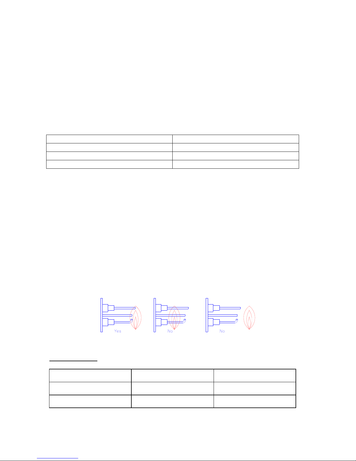
Proper Electrode Location
Proper location of the electrode assembly is important for optimum system
performance. The electrode assembly be located so that the tips are inside the
flame envelope and about ½ inch (1cm) above the base of the flame (Fig 6).
CAUTIONS
1. Ceramic insulators should not be in or close to the flame
2. Electrode assemblies should not be adjusted or disassembled. Electrodes
should have a gap spacing of 3.1 +/- 0.8mm. If this spacing is not correct, the
assembly must be replaced. Electrodes are NOT field adjustable.
3. Exceeding the temperature limits can cause nuisance lockouts and premature
electrode failure.
Fig 6
Injector Sizes:
GAS TYPE
MAIN JET
PILOT JET
NATURAL
2.80mm diameter
0.35mm diameter
L.P.G.
1.60mm diameter
0.23mm diameter
Page 10
Page 10 of 12 Mezzo Hanging Patio Heater 29/10/10
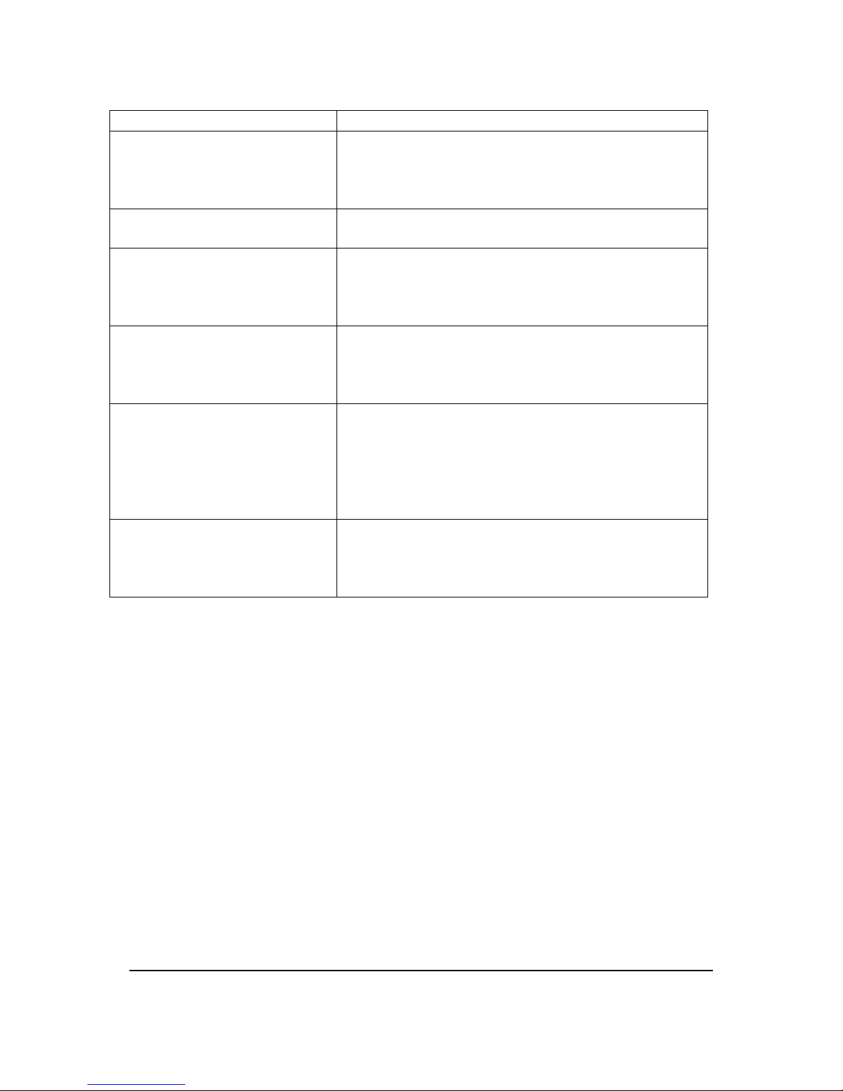
Service Checks
Symptom Cause/Cure
Electrically Dead 1. Miswired
2. Transformer bad
3. Fuse/Circuit breaker bad
4. Bad control (check LED for steady on)
Thermostat on – no spark 1. Miswired
2. Bad thermostat no voltage @ Terminal TH.
Valve on, no spark 1. Shorted electrode
2. Open HV cable
3. Miswired
4. Bad Control
Spark on, no valve 1. Valve coil open
2. Open valve wire
3. Bad control (check Voltage between V1 and
V2)
Spark on, gas supplied, no
ignition of the gas
1. Position of the spark is not in line with the
gas holes in the burner. Rotate the burner to
align the Flame to engulf the electrodes see
Fig 6
2. Adjust the Burner to bring the electrode to
with in 3 to 5mm of the burner.
Flame okay during TF, no
flame sense (after TFI)
1. Bad Electrode
2. Bad S1 or HV wire
3. Poor ground at burner
4. Poor flame (check flame current)
Warranty:
The Yunca MEZZO Hanging Patio Heater is covered by a limited two-year Warranty
against defects in materials and workmanship.
All gas components including control, burner, pilot assembly, tubing, regulator and
hose, are warranted for a period of one year from date of purchase.
Damage caused by neglect, improper use, acts of God, theft, or any other indirect,
incidental cause are not covered by this warranty.
This warranty is void if the recommended service schedule is not implemented as
suggested in this manual, and not carried out by a suitably qualified person.
Limitation of Liabilities
Yunca Heating hereby waivers any liability for incidental and consequential damage
directly or indirectly sustained, or for any loss caused by the application of this
product not in accordance with the current printed instructions.
Our liability is expressly limited to replacement of defective goods as per above
warranty. Any claim shall be deemed waived unless made in writing to us within 30
days from the date that it was or reasonably should have been discovered.
Page 11
Page 11 of 12 Mezzo Hanging Patio Heater 29/10/10
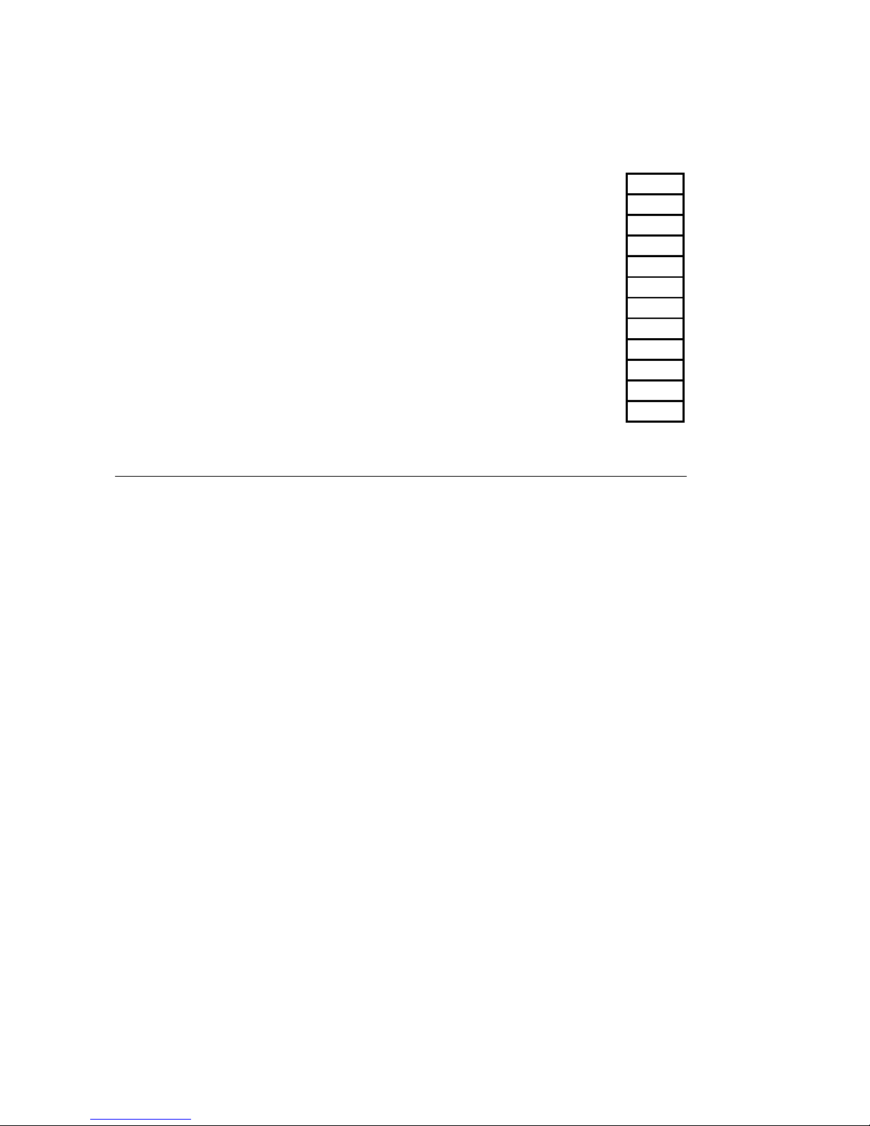
Table 1
PACKING PARTS HANGING PATIO HEATER
TICK
6524 Aluminium Reflective Dome
Horizontal Assy.
Vertical Channel x2 (one with Cable Ties)
6568PH Mounting Plate x2
Burner Assembly
Insulating Box with Transformer and fuse Carrier
M6 x 20mm Bolts x12
6mm Washers x12
M6 Nuts x12
0036C M6 X 26MM ALLOY FLAT WASHER (DOME, x6)
0007D M6 S/S WING NUT FOR DOME (X3)
Installation Instructions
DATE: SIGNED:
Page 12

Page 12 of 12 Mezzo Hanging Patio Heater 29/10/10
CUSTOMER COPY
YUNCA Mezzo Hanging Patio Heater WARRANTY REGISTRATION:
Serial No. Gas type. Purchase Date
Purchaser’s Name:
Purchaser’s Address:
City: Post Code: Telephone:
Where Purchased:
Installed By: Date:
Electrician: Phone:
Yunca Gas
PO Box 500, Dunedin 9054
Ph (03) 488 4342
Email [email protected]
Web Site www yunca.co.nz
Cut along this line
This section must be returned within 10 days of purchase.
YUNCA Mezzo Hanging Patio Heater WARRANTY REGISTRATION:
Serial No. Gas type. Purchase Date
Purchaser’s Name:
Purchaser’s Address:
City: Post Code: Telephone:
Where Purchased:
Installed By: Date:
Electrician: Phone:
Return to : Yunca Heating
PO Box 932
Invercargill 9840
 Loading...