

Page 1
Page 1 of 4
A division of Terry Young Ltd , New Zealand
INSTALLATION INSTRUCTIONS for
FITZROY FREESTANDING WOODBURNER
APRIL 2007
TESTED in compliance with AS/NZS 2918: 2001
A. Yunca recommends that competent trades persons carry out all installations (e.g. NZHHA
Registered Installer), to obtain maximum performance and safe, efficient heating.
B. A permit is required and we suggest you check with local building inspectors as by-laws do
vary from area to area.
Also notify your Insurance Company that a solid fuel heater has been installed.
C. Floor Protector –
1. Must extend a minimum of 300mm in front of the door aperture.
2. Must extend at least 100mm from each side of the heater.
3. Ash Floor Protector must be constructed of non-combustible materials, with a
minimum thickness of 12mm
D. Seismic restraint – Heater must be restrained from seismic movement as required by NZS
7421. 10mm diameter bolting holes in the feet of the HOBSON allow restraint.
E. Manufacturers’ recommended tested minimum clearances from combustible walls:
Tested to AS/NZS 2918 : 2001 by APPLIED RESEARCH SERVICES Clearance
Rear Clearance – from rear of top lip (with YUNCA flue mounted shield fitted)
- N.B. clearance from rear panel is 120mm
100 mm
Side Clearance (with YUNCA flue mounted shield fitted) 300 mm
Corner Clearance (with YUNCA flue mounted shield fitted) 130 mm
F. YUNCA Flue Kit (Tested to AS/NZS 2918:2001 Appendix F): Fig A, B & E
1. 4.2m x 150mm stainless steel flue 4. 1 x insulation boundary shield.
2. 2.4m x 250mm galvanised liner. 5. 3 x spider brackets.
3. 1 x ceiling tile. 6. 1 x weather cap & cowl.
Please Note: All joints must be sealed with flue sealing compound. Use stainless steel
screws or rivets to join the flue pipe (three equally spaced places at each joint). The first
length of flue pipe must be screwed to flue spigot. The required minimum flue termination
height is 4.6 m above the floor protector.
G. FITZROY Flue Mounted Shield (Flue Guard) Kit (Tested to AS/NZS 2918:2001): Fig A
1 x 1200mm length lined back guard plus an adjustable 900mm extension.
1 x 1200mm length perforated front guard
1 x 1200mm length tertiary back guard with spacer tabs.
1 x Top front deflector shield (half round shape, angled when installed). Optional.
Please Note: The minimum Flue Mounted Shield height Is 1200mm. Extension accessory
shields are also available.
Page 2
Page 2 of 4
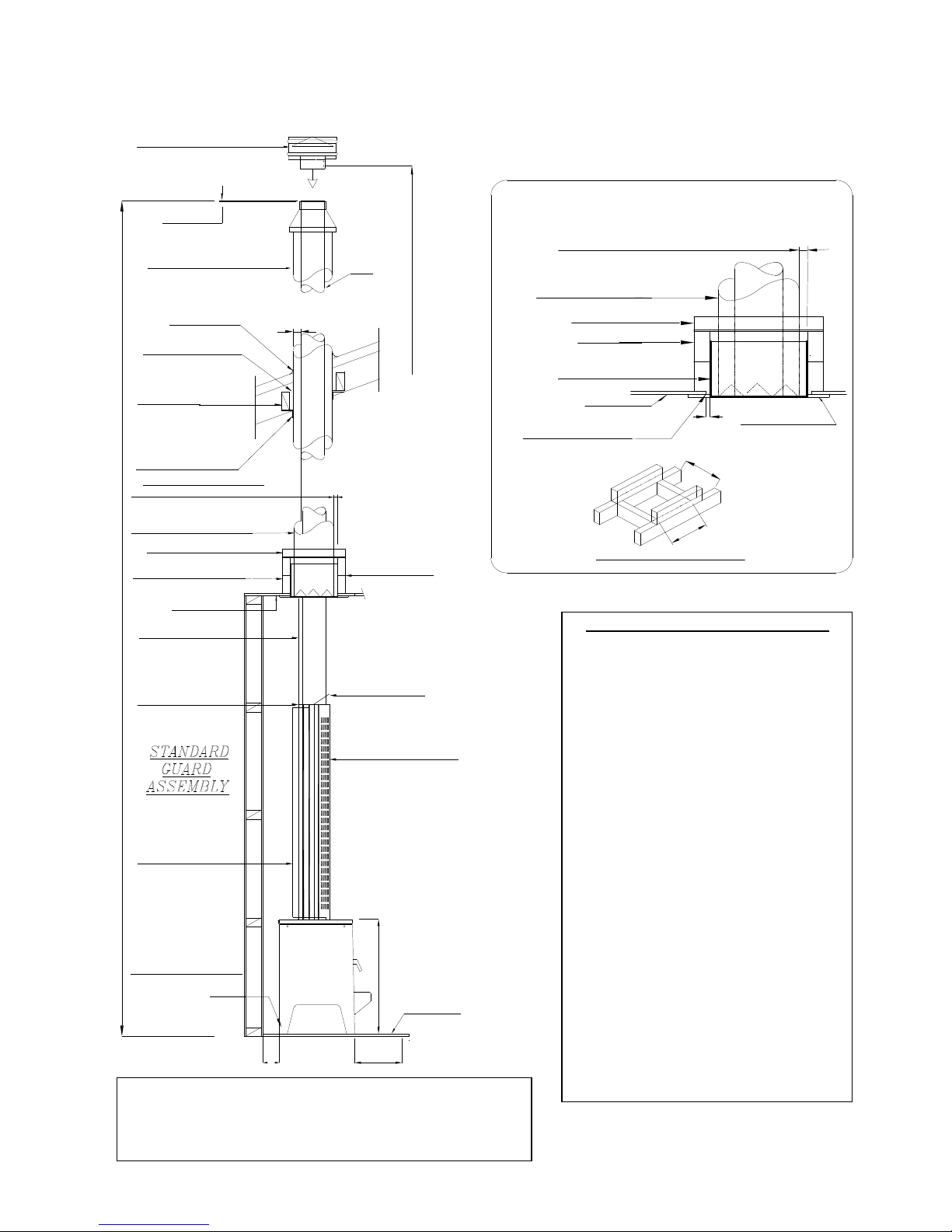
FITZROY – TYPICAL FLUE INSTALLATION (not drawn to scale)
FIG A FIG B
5mm Max
50
LINER POSITIONED BY SPIDER
BRACKETS. TOP/BOTTOM
FLUE
TOP CAP (Fits inside flue)
FLASHING
25 MM BETWEEN LINER
AND ANY TIMBER.
TIMBER RAILS
SUPPORT ANGLES
25 mm min BETWEEN LINER
& ANY TIMBER
LINER POSITIONED BY SPIDER
BRACKETS TOP & BOTTOM.
SUPPORT ANGLES
300mm sq TIMBER FRAME
CEILING
1200mm BACK GUARD
BACK GUARD
( Tertiary )
TWO SEISMIC RESTRAINT
attachment points.
cover with caps.
600mm ABOVE THE RIDGE LINE (MIN) *
* If within 3.0m of ridge line*
1200mm FRONT GUARD
4.6 M. MINIMUM
Note: All Dimensions are in millimetres.
ASH FLOOR
PROTECTOR
650
300
120
900 Extention
Top Front
Angled
Lined
Deflector
( Optional )
CONDITIONS FOR FLUES
(Refer Fig. E)
The FLUE shall extend to:
1.
Not less than 600mm above the highest
point on the roof if within 3.0m of that
point.
Not less than 1000mm above the
intersection point with the roof and not
lower than any point of the roof within
3.0m.
In any case the length of the flue shall not
be less than 4.6m from the ash floor
protector.
In some situations the Local Council may
vary the above requirements.
2. All parts of the chimney exposed to the
outside air shall be suitably insulated in
accordance with the manufacturers'
recommendations.
When loose- fill insulation is used in the
adjacent ceiling space, maintain clearance
between the secondary shield and the
loose-fill insulation by provision of a
boundary extending 200mm above the
ceiling top surface.
This non-combustible boundary shield
shall be capable of preventing accidental
migration of the loose-fill by any action of
wind or by persons moving in the ceiling
space.
Note: All measurements are in millimetres
The rear clearance from the top lip of the fire is 100mm,
i.e. 120mm from the (recessed) rear panel.
CEI LIN G PLA TE
25m m min . BE TWEE N L INER & ANY T IMBER
ENLA RG E ME NT O F CE ILING A SS EMB LY
3
0
0
300 mm Sq. TI MB ER FRA ME
TIM BER R AIL S
SUP PORT AN GL ES
LIN ER PO SITION ED BY SPIDE R
BRA CKET S. T OP/BO TTOM
LO OSE FILL BO UND ARY
SEC ONDA RY SH EIL D.
CUT CEIL ING MA TERIA L
BAC K 25m m CLE AR
OF BO UN DARY SH EIL D.
CE ILIN G
25
3
0
0
Page 3
Page 3 of 4
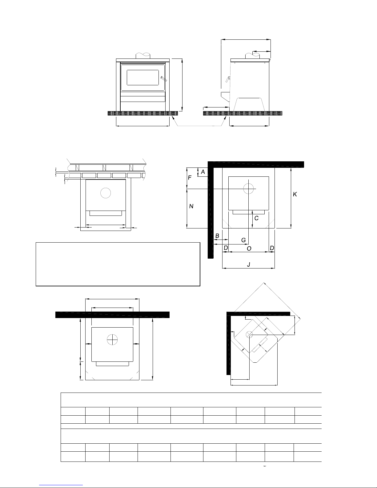
FIG C: HEATER DIMENSIONS – Fitzroy (Drawings on this page not drawn to scale)
640
Ash Floor Protector
490
300
650
560
225
FIG D: HEATER POSITION.
* N.B. Measurement “A” is taken from the top lip at the rear of the fire.
25
25
100
640
100
J
P
C
DD
O
K
C
N
H
M
L
E
E
D
D
H
FIG D: MINIMUM FIRE TO COMBUSTABLE WALL CLEARANCES - FITZROY
(WITH YUNCA FLUE MOUNTED SHIELD FITTED). Measurements in millimetres.
A B E F G H
100 300 130 325 620 501
FIG D: MINIMUM FLOOR PROTECTION MEASUREMENTS
(WITH YUNCA FLUE MOUNTED SHIELD FITTED). Measurements in millimetres.
C D J K L M N O P
300 100 840 910 1274 1150 575 640 610
Above: Non combustible wall clearances
. Brick lining
from floor to within 25mm of ceiling. Leave air vents at the
bottom to allow airflow in the cavity. If Yunca flue mounted
shield is fitted, brickwork may be 1200mm high as long as
all vertical joints in top and bottom of brickwork are left out to
allow airflow when brickwork is capped.
Page 4
Page 4 of 4
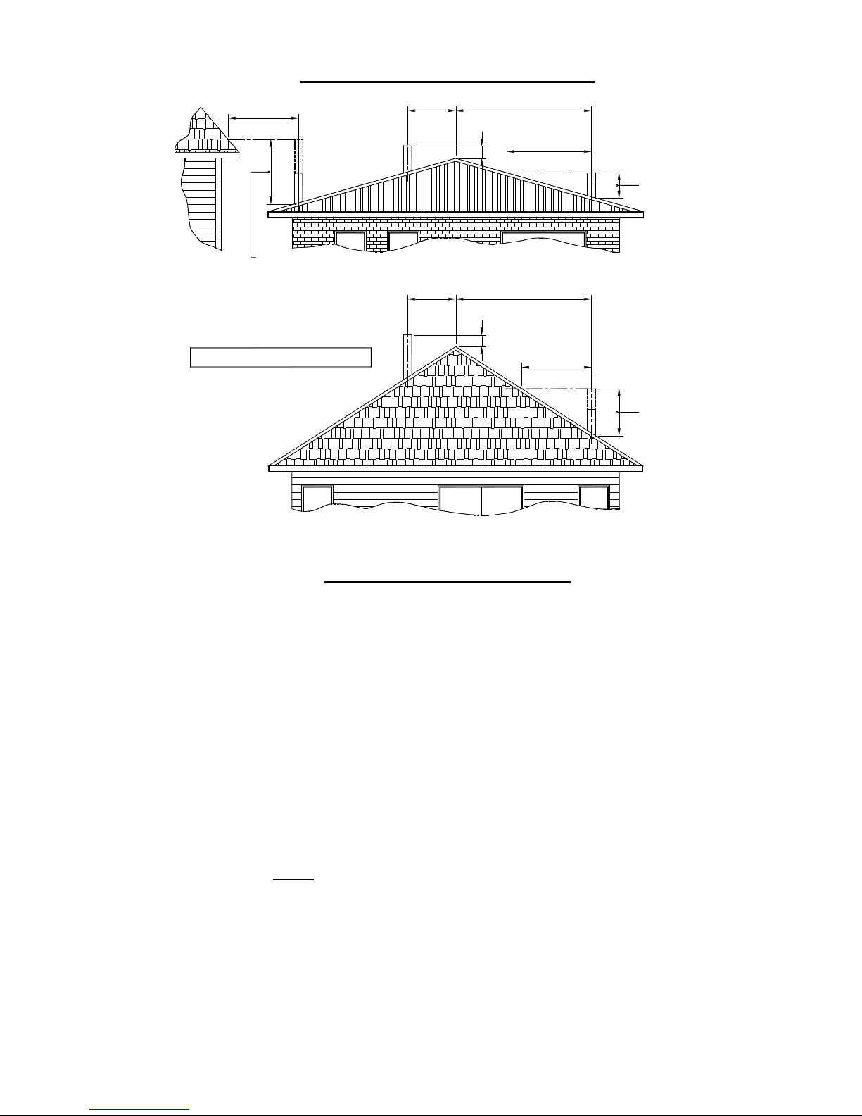
FLUE SYSTEM REQUIREMENTS FIG. E
More than 30003000
or less
600 min.
3000
1000 min. if clear
within 3000 of
flue top
.
3000
Any nearby
structure
.
1000 min. if clear
within 3000 of
flue top
MINIMUM HEIGHT OF FLUE SYSTEM EXIT
NOTE : Dimensions are in millimetres
3000
or less
600 min.
More than 3000
3000
.
Increase from
1000 min. until
clear within
3000 of flue top
IMPORTANT INFORMATION
A. The appliance and flue system shall be installed in compliance with AS/NZS 2918 and the appropriate
requirements of the relevant building code or codes.
B. Appliances installed in accordance with this standard shall comply with the requirements of AS/NZS
4013 where required by the regulatory authority i.e. the appliance shall be identifiable by a compliance
plate with the marking “TESTED TO AS/NZS 4013”
C. Any modification of the appliance that has not been approved in writing by the testing authority is
considered to be in breach of the approval granted for compliance with AS/NZS 4013
D. Mixing of appliance or flue system components from different sources or modifying the dimensional
specification of components may result in hazardous conditions. Where such action is considered, the
manufacturer should be consulted in the first instance.
E. Cracked and broken components e.g. glass panels or fire bricks, may render the installation unsafe.
IF THE A WATERBOOSTER IS FITTED:
Note: A water booster cannot be fitted to the Sub 1.0 Clean Air model Fitzroy
A. Do not connect to an unvented hot water system
B. Install in accordance with AS 3500.4.1 or NZS 4603 and the appropriate requirements of the relevant
building codes.
Seismic Restraint
Secure the heater base to the hearth or sub-framing with dynabolts or similar through the holes provided.
Follow local Council’s Specifications.
 Loading...