

Page 1

Product Manual
Applicable model: MF20
Laser Marking Machine
I
Page 2

Copyright Statement
GD Han’s Yueming Laser Technology co.,Ltd.
All rights reserved.
GD Han’s Yueming Laser Technology co.,Ltd (Han’s Yueming Laser hereafter) reserves
the right to modify the products and product specifications described in this manual without
advance notice.
Han’s Yueming Laser is not responsible to any direct, indirect, or consequential damage or
liability caused by improper use of this manual or the product.
Han’s Yueming Laser owns the patent, copyright or any other intellectual property right of
this product and the related software. No one shall duplicate, reproduce, process or use this
product and its parts, unless authorized by Han’s Yueming Laser.
All the name refered in this manual only for identification, if belongs to other company’s
registered trademark or copyright, proprietary rights of the name belongs to their respective
holder.
II
Page 3

Disclaimer and Responsibility Statement
Whole using the machine from our company, users are required to ensure integrity and
independence of the product including but not limited to: mechanical, electrical, optical, control
software and accessories. Unauthorized modification is strictly prohibited. It is a must to satisfy
operating environment and operating specifications specified in the owner’s manual.For the
followings:
Machine modified with no authorization (including but not limited to: add, remove,
modify, unauthorized disassembly, replacing parts);
Use the machine in the environment failing to satisfy the operating requirements;
Operate disobeying the specifications of our company;
Unauthorized use the machine parts, accessories and auxiliaries on to other machine or
in other places;
Viciously disassemble, destroy, decode hardware and software of the machine from
our company
Our company shall not undertake any direct, indirect or joint responsibility. Our company
reserves the rights to ascertain legal responsibility for the serious consequences or economic
losses or reputation losses caused by what mentioned above.
III
Page 4
Foreword
Alarm
Special Attention: User must follow and perform as the manual. Otherwise, it
could lead to errors or relatively serious problem.
Note
Note: User should comply with the attention and suggestion in this manual. it
could bring much easier operation.
Thanks for purchasing the laser engraving machine control system of our company.
Before operating, please read this manual carefully to ensure proper operation.
Please keep the manual properly for reference.
Since the configs are different, certain models do not have the functions listed in this
manual. Please refer to the specific functions for details.
Due to the constantly tech update, the specification for reference only, subject to the real
standard.
Tags in this book:
IV
Page 5
Safety Precautions
Attention
▴Before using the machine, users are required to carefully read this manual and other operating
requirements, strictly abide by the operating specifications. Professional are required for operating
the machine.
Attention
▴ The machine uses class 4 laser (strong laser radiation). The laser radiation may possibly cause
the following accidents: ① emblaze the surrounded flammable materials; ② generate other
radiations and toxic or hazardous gas by processed objects during laser processing; ③ direct
irradiation of laser radiation cause harm to human body. Therefore, firefighting devices are
required in the operating place of the machine. Stacking flammable or explosive objects near the
machine is strictly prohibited. Good ventilation is a must. Only the qualified personnel are
authorized to approach the machine.
Attention
▴ The processed objects and discharged materials are required to satisfy requirements as per local
laws and regulations.
Attention
Laser processing is with potential risks. Users should carefully make sure if the processed
objects are suitable for laser processing.
There is high voltage and potential risk in the laser machine. Unauthorized disassembly by
unqualified personnel is prohibited.
Reliable earthing is required for the machine and related other machine before power-on.
During operating, removing any cover of the machine is strictly prohibited.
During operating, the operators are required to observe working status of the machine all the
time. In case of any abnormality, it is immediately to disconnect power supply and take active
and corresponding measures.
After power-on, special personnel are required for monitoring. Unauthorized leaving is strictly
prohibited.
It is a must to disconnect the power supply before leaving.
Attention
It is strictly prohibited to placing any unrelated all-reflective or diffusion reflective objects in
the machine to prevent laser reflecting to human body or flammable materials.
Attention
The environment for the machine should be dry, free of interference and influences from
pollution, vibration, high voltage and strong magnet. The operating ambient temperature
ranges 5-40℃, and the humidity ranges 5-95% (no dew);
The machine should be far from electric appliances sensitive to electromagnetic interference;
Operating voltage: AC220V, 50Hz. Power-on is strictly prohibited in case of unstable voltage
of the power grid or unspecified voltage.
Attention
Chapter two of this manual is for Safety Rules. Please refer to the chapter more details
concerning safe operation of the machine. Users are required to carefully read and abide by
all the requirements of safety.
V
Page 6

Table of Contents
Copyright Statement ......................................................................................................... II
Disclaimer and Responsibility Statement ......................................................................... III
Foreword .......................................................................................................................... IV
Safety Precautions ............................................................................................................. V
Table of Contents ............................................................................................................. VI
Equipment Overview .................................................................................. 1 Chapter 1
1.1 Equipment Composition ......................................................................................... 2
1.1.1 Overall Components ....................................................................................... 2
1.1.2 Mechanical Components ................................................................................ 4
1.1.3 Optical Components ....................................................................................... 5
1.1.4 Electrical Components .................................................................................... 6
1.2 Equipment Parameters ........................................................................................... 8
1.3 Product Configuration ............................................................................................. 9
1.4 Operating Environment......................................................................................... 10
1.5 Suitable Materials ................................................................................................. 10
1.6 Application ............................................................................................................ 10
Safety Rules ............................................................................................... 11 Chapter 2
chapter2..................................................................................................................... 11
2.1 Warning and signs ................................................................................................. 11
2.2 Product safety ....................................................................................................... 11
2.3 Safe equipment ..................................................................................................... 11
2.4 Safety awarenes .................................................................................................... 12
2.5 Requirements for personnel ................................................................................. 12
2.5.1 Definition of terms ........................................................................................ 12
VI
Page 7

2.5.2 Qualifications ................................................................................................ 13
2.5.3 Responsibility ................................................................................................ 13
2.5.4 Personal protective devices .......................................................................... 13
2.6 Special product risks ............................................................................................. 13
2.6.1 Laser radiation risk ........................................................................................ 13
2.6.1.1 Common mode .............................................................................................. 14
2.6.1.2 Direct laser .................................................................................................... 14
2.6.1.3 Reflection and diffuse radiation .................................................................... 14
2.6.2 High voltage risk ............................................................................................ 15
2.6.3 Risk of electric shock ..................................................................................... 15
2.6.4 Risk of process by product ............................................................................ 16
2.6.5 Risk of optical system .................................................................................... 17
2.6.5.1 Routine operation ......................................................................................... 17
2.6.5.2 Warning for fire accident .............................................................................. 18
2.6.6 Other risks ..................................................................................................... 18
2.6.7 Measures for emergency .............................................................................. 18
2.6.7.1 Measures for personal injury ........................................................................ 18
2.6.7.2 Measures for fire accident ............................................................................ 18
chapter3. Equipment Installation and Commissioning ............................................. 19
3.1 Equipment Installation .......................................................................................... 19
3.1.1.1 Unpacking Steps ............................................................................................ 19
3.1.1.2 Unpacking ...................................................................................................... 20
3.1.1.3 Preparation ................................................................................................... 21
3.1.2 Installation Steps ........................................................................................... 21
3.1.2.1 Installing Fiber Laser Marking Cavity ............................................................ 21
3.1.2.2 Installing Computer, Keyboard & Mouse ...................................................... 22
VII
Page 8

3.1.2.3 Installing Scanning Focus Lens ...................................................................... 22
3.1.2.4 Connecting Galvanometer Cable .................................................................. 23
3.1.2.5 Installing Footswitch ..................................................................................... 23
3.1.2.6 Installing Sensor and Encoder (marking on the fly optional) ........................ 23
3.1.2.7 Equipment Grounding ................................................................................... 23
3.2 Buttons and Indicators Description....................................................................... 26
3.2.1 Installing Other Accessories .......................................................................... 27
3.3 Equipment Debugging ........................................................................................... 28
3.3.1 Switch sequence ........................................................................................... 28
3.3.2 Galvanometer Marking Test ......................................................................... 28
3.3.3 Laser Test ...................................................................................................... 28
3.3.4 IO Test ........................................................................................................... 28
3.3.5 Sensor and Encoder Test (optional) .............................................................. 29
chapter4. System Maintenance ................................................................................ 30
4.1 Mechanical Maintenance ...................................................................................... 30
4.2 Electrical Maintenance .......................................................................................... 30
4.3 Maintenance of Optical Path and Optical Devices ................................................ 30
4.4 Auxiliary Machine Maintenance ........................................................................... 32
chapter5. Troubleshooting ........................................................................................ 33
Appendix .......................................................................................................................... 35
Appendix 1 Electrical Control System Block Diagram of Main Power ......................... 35
5.1.1 ...................................................................................................................... 35
Post .................................................................................................................................. 36
VIII
Page 9
Equipment Overview Chapter 1
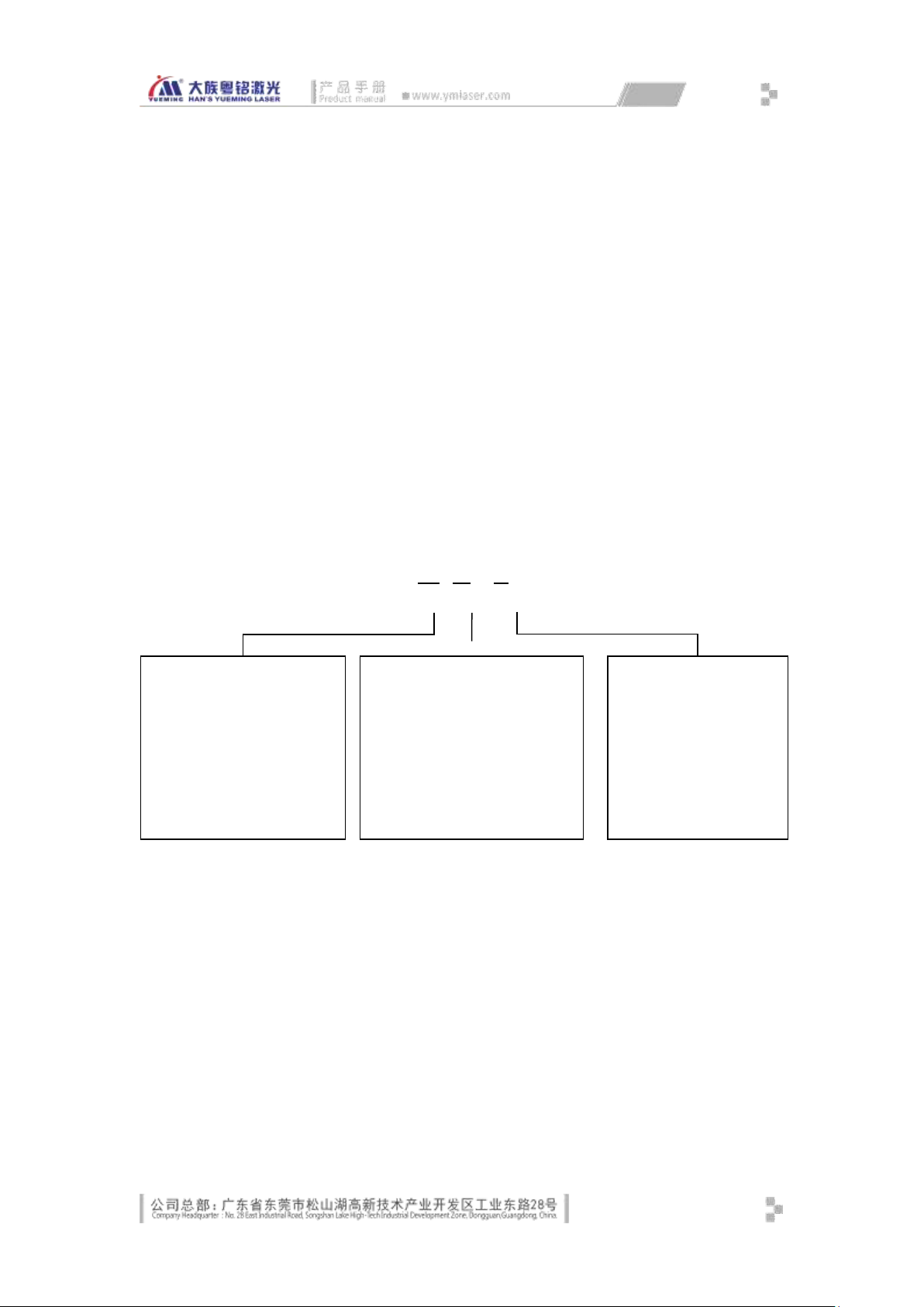
P: Portable
MF
XX
-A
MF20 is a new generation fiber laser marking machine, which adopts modular design. The
optical bench, working platform and elevating working platform are separated and also can be
freely combined, which greatly improve the product's adaptability and flexibility. It is configured
with the new digital marking control system and powerful upper machine software, which can
meet the marking applications of different industries. It applies to stationary work surface
marking, rotary marking, mobile stitching marking, as well as assembly line marking on the fly.
The optical bench features multiple DOF adjustment functions (6 DOF), allows multi-directional
multi-angle rotation, and applies to the marking on different work surfaces. The core laser and
optical system are imported high-performance foreign products, which ensure that the machine
features better marking performance, higher accuracy, faster and more stable.
Description of equipment model:
Equipment series:
MF: Fiber laser marking
machine
……
Laser power:
20: 20W
……
Fig. 1-1 Description of Equipment Model
Auxiliary model
description:
A: Common
B: Offline embedded
C: Europe and America
1
Page 10
1.1 Equipment Composition
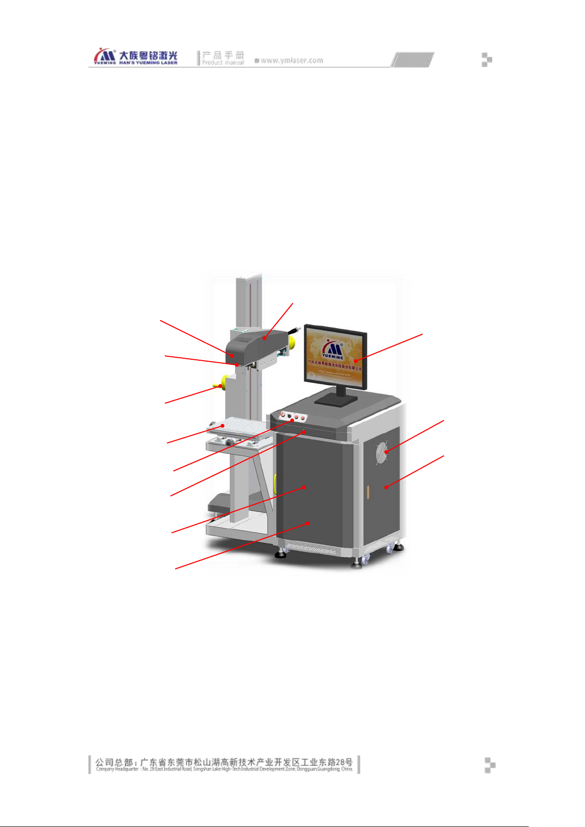
① Optical scanner galvanometer
② Optical scanner
field lens
③ Elevating
handwheel
④ XY adjustment platform
⑤ Operation panel
⑥ Keyboard drawer
⑦ Host computer
(internal)
⑧ Fiber laser (internal)
⑨ Fiber output head
⑩ Monitor
⑪ Cooling fan
⑫ Electrical box (internal)
○
2 ○1 ○9 ○3 ○4 ○10
○
5 ○7
○
8
○
11
○
12 ○6
Due to different machine models and product update, some models may have different
appearances and details. The actual product shall prevail. Below is the equipment composition of
MF20.
1.1.1 Overall Components
The front view of the machine is as shown in Fig. 1-2:
Fig. 1-2 FRONT VIEW
2
Page 11
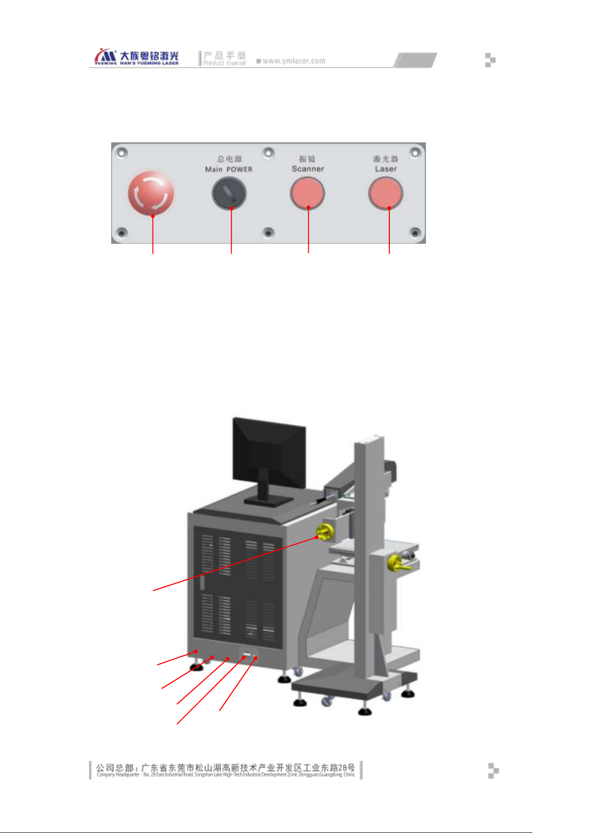
① Emergency stop button
② Main power key switch
③ Galvanometer
self-locking illuminated
pushbutton
④ Laser self-locking
illuminated pushbutton
①
⑤
⑥
②
③
④
② ③ ④ ⑥ ⑤
The operation panel is as shown in Fig. 1-3:
Fig. 1-3 Operation Panel
The rear view of the machine is as shown in Fig. 1-4:
3
Page 12
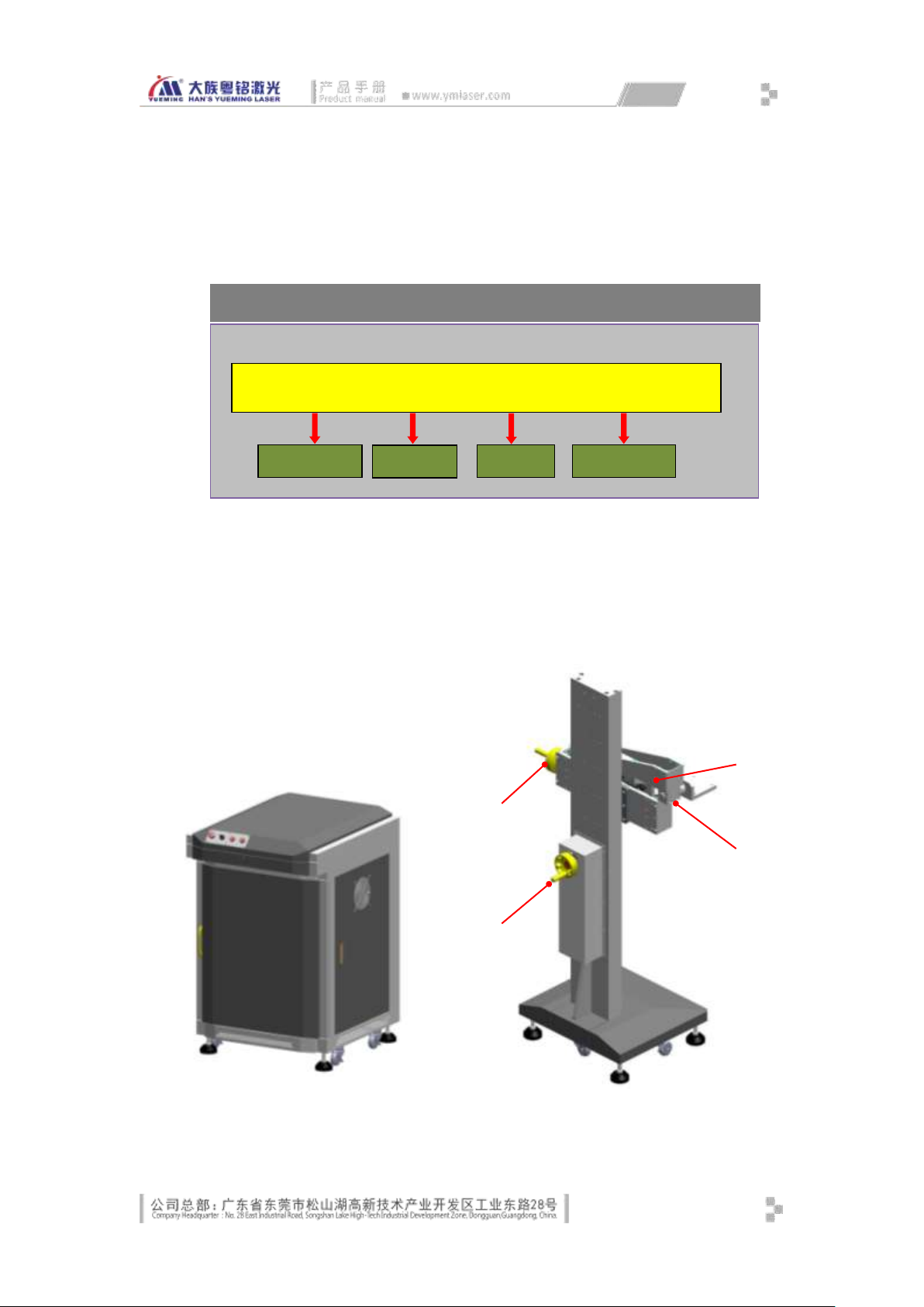
Fig. 1-4 Rear View
① Front & rear hand wheel
② Main power cord port
③ Sensor aviation plug
④ Encoder aviation plug
⑤ Corrugated pipe inlet port
⑥ Fiber optic cable port
① Front & rear adjustment
② Up & down adjustment
③ Pitch angle adjustment
②
③
①
④
Machine Structure
Optical
Marking on the
Control System
Rotating
Galvanometer
The overall control schematic drawing of the machine is as shown in Fig. 1-5 below:
Fig. 1-5 Overall Machine Control Diagram
1.1.2 Mechanical Components
The mechanical part consists of the console, base, workbench with XY adjustment
platform (optional), assembly line (optional), and rotating platform (optional).
Fig. 1-6 Console Diagram Fig. 1-7 Base Diagram
4
Page 13
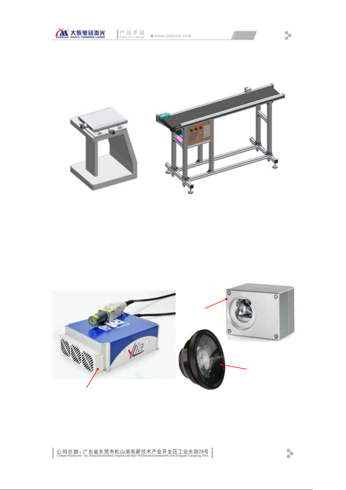
④ Rotation angle
① Fiber laser
② 2D scanning
③ Scanning
①
②
③
Fig. 1-8 Workbench Diagram
(optional)
1.1.3 Optical Components
Fig. 1-9 Assembly Line Diagram
(optional)
Fig. 1-10 Optical Mechanism of the Machine
5
Page 14
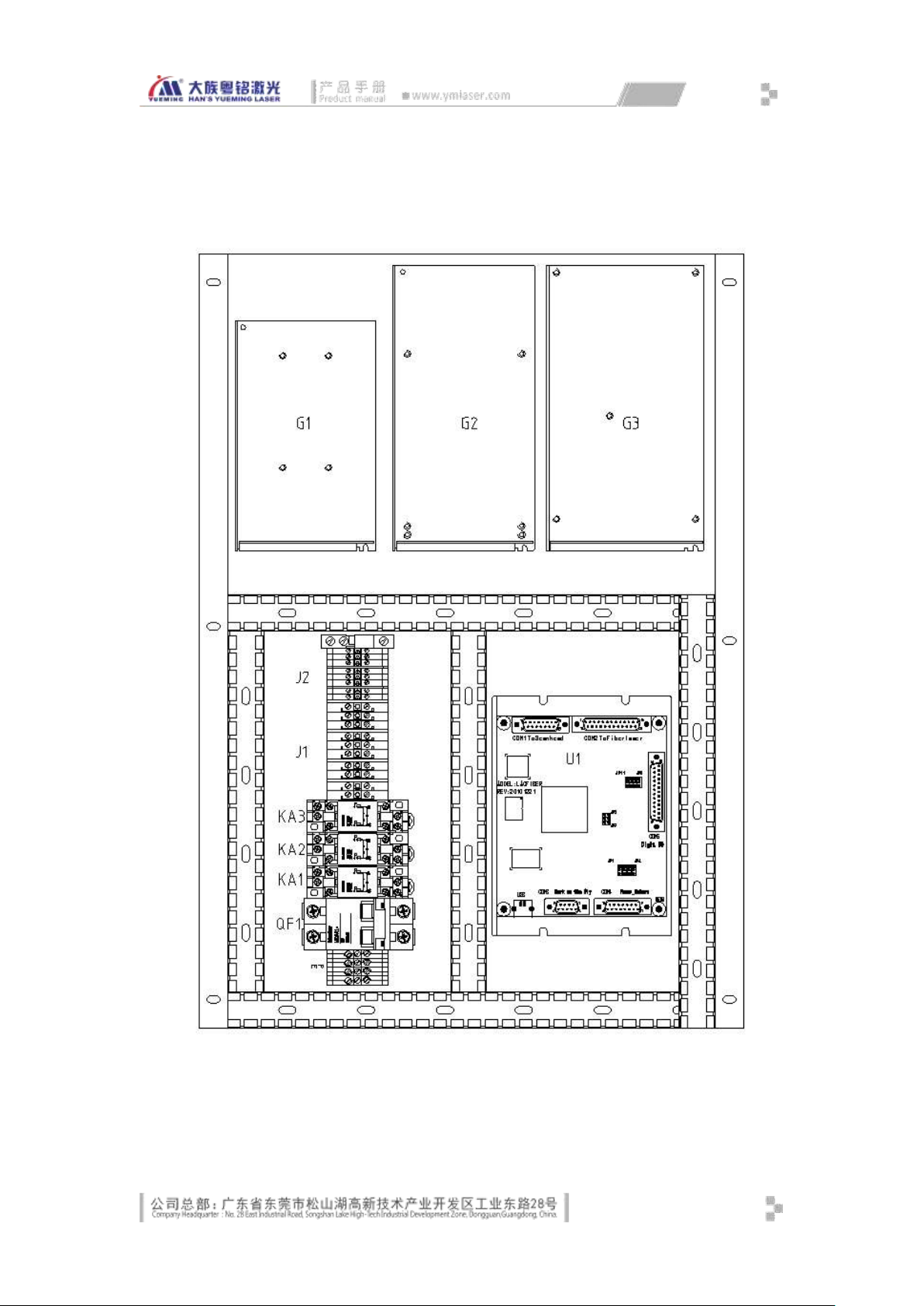
1.1.4 Electrical Components
Layout of electric control box
Fig. 1-11 Layout of Electric Control Box
6
Page 15
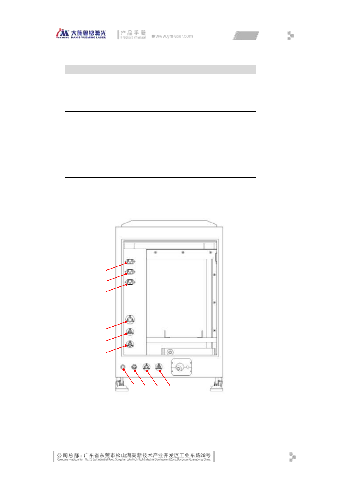
Components of the electrical control box
Component
Name
Function
G1
Switching power supply
Control loop & marking card power
supply
G2
Switching power supply
2D scanning galvanometer power
supply
G3
Switching power supply
Fiber laser power supply
U1
Fiber laser marking card
USB marking card
J2
Terminal
Control loop power distribution
J1
Terminal
Main loop power distribution
KA3
Intermediate relay
Laser power control
KA2
Intermediate relay
Galvanometer power control
KA1
Intermediate relay
Main loop power control
QF1
Breaker
Main loop energization control
PE
Ground terminal
① Computer
② Monitor
③ AC output
④ DC output
⑤ Galvanometer
power supply
⑥ Reserved
⑦ AC input
⑧ Pedal input
①
②
③
④
⑤
⑥
⑦ ⑧ ⑨
⑩
Description of electrical control box connector
Fig. 1-12 Electrical Control Box Connector Diagram
7
Page 16

⑨ Sensor input
⑩ Encoder input
1.2 Equipment Parameters
Series of laser equipment
Model: MF20
110 X 110 MM
10%50/60Hz_______
1000 W
___________________________
Website: http://www.ymlaser.com
The equipment parameters are different due to the model and configuration. The actual
product nameplate and attached factory parameters shall prevail. The nameplate is usually on
the back or the left side of the machine. Below is the nameplate of MF20:
Laser Type: Fibe
Laser Power: 20W
Operating Area:
Power Supply::_______220V±
Total Power: <
Manufacturing No:
Date of Manufacture: June, 2013
Manufacturer:Guangdong Han’s Yueming Laser Tech Co.,
Ltd.
Tel:0769-89838888, 89839999
Han’s Yueming Laser Equipment
Model: MF20
Resolution:
Laser Type: Fiber
Laser Power: 20W
Operating Area: 110×110mm
Power Supply: AC220V±10% 50HZ/60HZ
Total Power: < 1000W
Manufacturing No.:
Date of Manufacture: June, 2013
Manufacturer: Guangdong Han’s Yueming Laser Tech Co., Ltd.
Tel: 0769-89838888, 89839999
8
Page 17
Website: http://www.ymlaser.com
Master
Unit
No.
Item
Configuration
Specification
Qty.
Manufacturer
Matching
Item
Remark
1
Laser ● 20W
1
Quantel
2
Galvanometer
●
Raylase
1
Imported 1
3
Field lens
●
SL-1064-112-163G
1
Wavelength
Marking format: 110mm
× 110mm, f = 163mm
4 ○ SL-1064-140-210
1
Wavelength
Marking format: 140mm
× 140mm, f = 210mm
5 ○ SL-1064-70-100
1
Wavelength
Marking format: 70mm ×
70mm, f = 100mm
6
Working
platform
○
X/Y moving
platform
1
Han's
Yueming
Moving distance is about
50mm
7
○
Assembly line
workbench
1
Han's
Yueming
This workbench is made
to order
8 ○ Rotating claw plate
1
Han's
Yueming
9
○
Rotating disk
workbench
1
Han's
Yueming
Disc diameter 300mm
10
Lifting frame ○
1
Han's
Yueming
Lifting range is about
600mm
E-mail: [email protected]
Fig. 1-13 Machine Nameplate
The machine parameters on the nameplate are as follows:
Model: The machine model; see Section 1.1 for details (Fig. 1-1);
Laser Type: Laser type of the machine, mainly fiber laser;
Laser Power: Rated power of the laser;
Operating Area: Processing range of the equipment;
Power Supply: The total input power of the equipment, typically AC 220V; export
models vary by country;
Total Power: The rated power of the equipment while operating;
Manufacturing No.: a unique number of each machine;
Date of Manufacture: The production date of the machine;
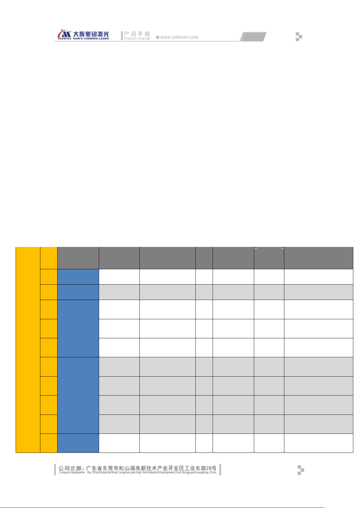
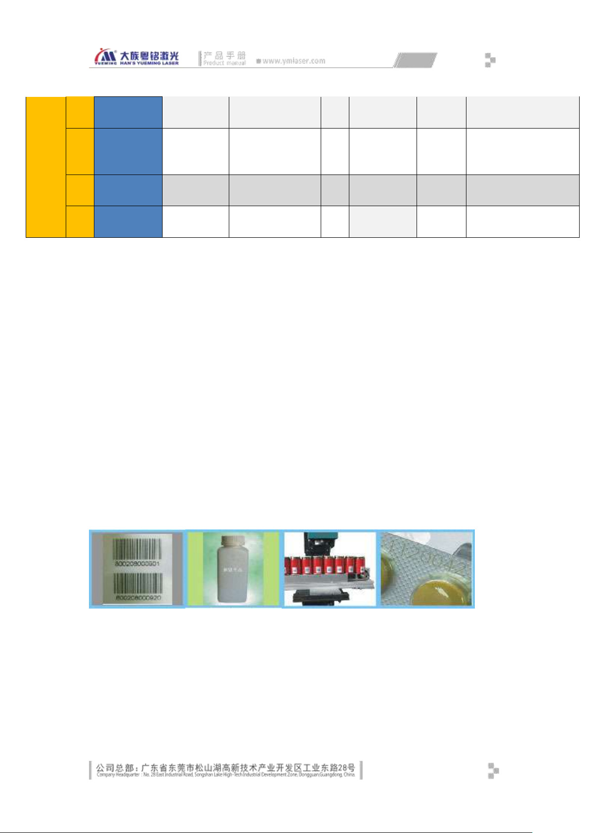
1.3 Product Configuration
9
Page 18
11
Control box ●
1
Han's
Yueming
12
Computer ●
1
Lenovo
English Win7
Professional Edition is
optional
13
Control board
●
MM
1
Han's
Yueming
14
PC software
●
SmartScanner
1
Han's
Yueming
●: Standard configuration; ○: Optional configuration; △: Configuration can be added; ▲: Used in conjunction with other items;
╳: No such configuration
Table 1-1 Configuration Table
1.4 Operating Environment
Humidity: ≥ 80% (non-condensing)
Temperature: 24℃±2℃
Power supply: AC220V; 50/60Hz
Grounding: ground resistance should be less than 5Ω
Equipment environment should be dry, smokeless, no dust, no strong magnetic field
interference
1.5 Suitable Materials
Plastic, metal surface, oxide layer
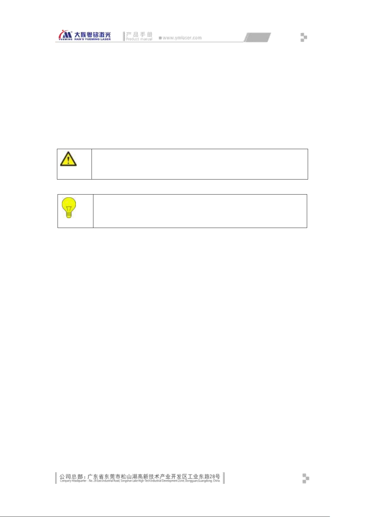
1.6 Application
It is widely used in food and beverage, pharmaceutical, tobacco, leather, packaging,
building materials, cosmetics, electronic components and other industries, featuring low
consumption, non-toxic and non-polluting. It can be used with our assembly line workbench
or existing assembly line of the company.
10
Page 19
Safety Rules Chapter 2
Warning
May possibly cause serious harm to human body or danger to life and property
Note
What the operator and maintenance personnel should pay attention to
This chapter mainly introduces safety warnings for protecting personnel and the machine,
and makes an introduction to signs used in the owner’s manual. The machine is already equipped
with sufficient safety guarantee, yet it is still with certain risk. All the operators are required to
carefully read through and well understand the safety rules.
2.1 Warning and signs
2.2 Product safety
The following conditions are required to be satisfied to ensure safe work:
Abide by operation manual and instruction signs;
Operators and maintenance personnel have received training held by machine
manufacture;
In case of operation by couples of person at the same time, division of responsibility
should be made and followed;
No admission to the working area for the unauthorized personnel;
Avoid any working method breaking the safety rules;
Timely eliminate all the failures possibly causing lower safety coefficient;
Abide by maintenance regulations of the machine.
2.3 Safe equipment
Safety equipments are used for protecting personnel, and unauthorized disassembly,
bridge-group or by-pass connection are strictly prohibited; in case of failure with the safety
machine, professional are required for repair. If part replacement is needed, the product with
same model, specification and from the same manufacture is required; otherwise, written
consent from the manufacturer is required.
11
Page 20

2.4 Safety awarenes
The machine can be operated only by skilled personnel or under supervision of them.
Improper use or operation may possibly be very dangerous and cause damage to the machine.
Therefore, the followings are strictly prohibited:
Placing heavy objects or stepping on the working table of the machine;
Used for processing the materials unapproved by manufacturer;
Staying of unauthorized personnel in the dangerous area (It is the responsibility of
operators to ensure keeping unauthorized personnel away from the working area.);
Block of using emergency stop button (Regular check is required to ensure a good
condition for the emergency stop button.)
2.5 Requirements for personnel
After trail operation, maintenance personnel from the manufacturer may perform training
on the operators.
It is the responsibility of machine owner to have operators trained at corresponding level.
We have prepared ready a series of training course for your option. Please make phone call
to our Customer Training Center for details.
2.5.1 Definition of terms
All the personnel using or operating the machine are called User in the manual;
Different requirements are for different users. Users are classified into the followings:
Owner
Owner means the authorized person or representative to sign contract with the
manufacturer. With authorization, the owner has rights to sign the agreement with binding force
of law;
Operator
Operator means the personnel trained for operating the machine. Training of the operator
includes participation of training held by the manufacturer.
Maintenance personnel
Maintenance personnel mean the technicians having received formal training for
machine and electric engineering. The maintenance personnel are responsible for daily
maintenance of the machine, and repair at low level if needed. Training on the maintenance
personnel contains participation training held by manufacturer.
12
Page 21
2.5.2 Qualifications
Note
Personal protective devices shall not be provided together with the laser marking
machine.
The operator is required to accept guidance and training of the owner, and the operator is
responsible for the safety of a third party in the working area; the personnel required for further
training and guidance are required work or operate the machine under supervision of the
operators.
2.5.3 Responsibility
It is a must to clarify the related responsibilities of each performance (operation,
maintenance, parameter setting), and carry it out. Unclarified responsibilities will cause safety
hidden risks.
Owner is required to provide operation manual for the operators and maintenance
personnel, and ensure that they have read and understood the operation manual.
2.5.4 Personal protective devices
When technology or measures fail to absolutely avoid risk of health, the owner is required
to provide personal protective devices for operator and maintenance personnel. For example,
Protective gloves;
Laser-proof goggle;
Light respirator
2.6 Special product risks
2.6.1 Laser radiation risk
Based on level of potential risk of laser radiation, the national standard GB 7247.1-2001
makes classification for them. Laser class applicable for this laser marking machine depends on
operation mode. The followings are abstract of laser device classification prescribed by the state:
Class 1: safe laser device under reasonable and foreseeable working conditions
Class 2: laser device is emitting visible light at wave length of 400nm-700nm. Generally,
avoidance response including blink reflection provides protection.
Class 3A: safe laser light visible to naked eyes. Generally, avoidance response including blink
reflection provides protection. Harm to naked eyes of other wave lengths will be less Class 1
13
Page 22
laser device. Class 3A light beam internal observation with optical device (e.g. glasses, telescope,
Note
This machine is a class 4 laser device. Placing high reflection objects (e.g. glass, mirror)
in eth laser working table is prohibited.
Note
Common working mode must ensure:
Laser light route is in safety protection mode;
Correct operation of the laser marking machine;
Materials to be processed have been verified suitable for laser processing with 10.6μm
wave band
and microscope) may be dangerous.
Class 3B: dangerous laser device is to directly and internally see light beam. Generally,
observation of diffuse reflection is safe.
Class 4: laser device with diffuse reflection causes danger. They may possibly cause skin
burn, or fire accident. Great care is required to use this kind of laser device.
2.6.1.1 Common mode
In the normal operating mode, the laser marking cutting machine equals to Class 4 laser
radiation. In this operating mode, there will harm of laser radiation to eyes and skin; you are
required to wear goggles with antiglare filter.
2.6.1.2 Direct laser
You are required to pay attention to the followings while operating the laser machine:
It is strictly prohibited to directly expose any parts of human body, explosive object and
flammable objects to direct laser;
Modification of fasteners on the optical parts is strictly prohibited;
Unauthorized change of light route is strictly prohibited;
Abide by all instructions prescribed in the operation manual.
2.6.1.3 Reflection and diffuse radiation
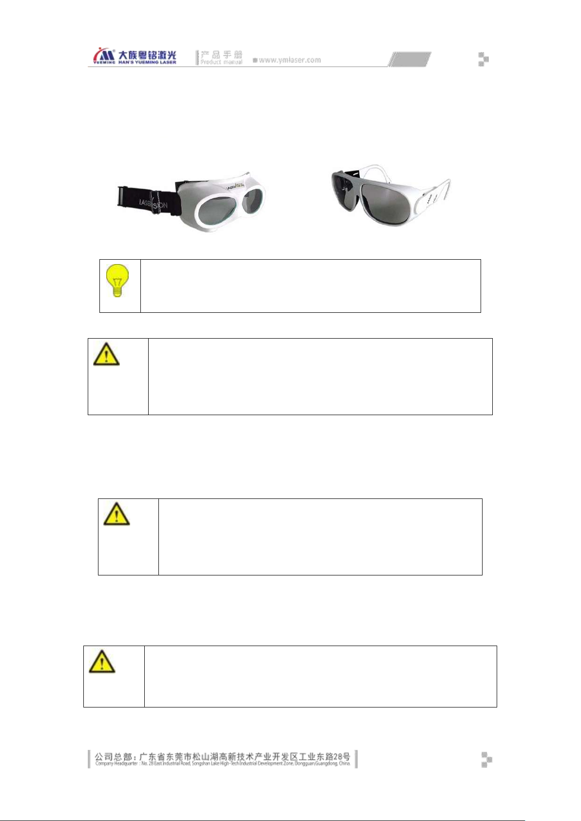
Avoid exposing eyes and skin to mirror reflection and diffuse radiation. In the maintenance
mode, the maintenance personnel are required to wear laser-proof glasses, and the laser-proof
glasses should satisfy the requirements as per EU standard EN207A1:2002.
14
Page 23
Note
Wavelength of CO2 laser device of this class is 10.6μm and it is a class 4 laser device;
You are recommended to use SD-5 type of protective glasses made by Shield
Company.
Warming
You are prohibited to directly watch strong light and laser even with laser-proof glasses
on;
Laser-proof glasses are made from high polymer material, and dipping into organic
solvent or cleaning with it are prohibited;
It is a must to replace the laser-proof glasses at the expiration.
Warming
High voltage 220V!
The voltage over 50V and the current over 20mA are with the risk of danger and
may cause death.
Only the maintenance personnel from the manufacturer are permitted to
perform operation on the inner parts
Warming
While operating electric machine or device, mis-operation or neglect during operation
may possibly cause serious hurt or human body or even death;
Technicians with related qualifications are required for operating the electric machine or
device or perform operation under their supervision.
Version of glasses wearing
Standard design
2.6.2 High voltage risk
The external power supply is at 220V.
2.6.3 Risk of electric shock
The followings are required for operating of installing the electric machine:
15
Page 24

It is a must to use the specified fuse provided by the manufacture;
Immediate pressing the emergency stop button is required in case of power failure;
Unless otherwise prescribed, power disconnection of the electric part is required for
maintenance;
First check if there is live power on the insulated part, and then perform the treatment
of earthing and open circuit, and perform insulation for the nearby live (charge) parts;
Make regular check on the electric machine. Timely correct failure like poor contact or
burnt power cord;
While operating live (charge) parts, minimum two persons are required at the site for
pressing the emergency stop button or disconnecting power supply if necessary; Mark
the working area with red-and-white band and warning sign;
It is a must to use insulation tools.
2.6.4 Risk of process by product
During laser processing, outgrowth may possibly generate, and their hazard must satisfy the
requirements specified in Appendix A for example of processing outgrowth as national standard
GB 18490-2001 laser processing machine. The abstract is as below:
A1.1 china processing
The oxide of Al2O3, Mg, Ca and Si; BeO (virulent).
A1.2 silicon slice processing
Crumb of silicon and silicon monoxide suspended in the air (possibly breathed into lungs
causing silicosis);
A1.3 metal processing
In a view of medicine, the following metals and their compounds are influential: Mn, Cr, Ni,
Co, Al, Zn, Cu, Be, Pb, Sb
Medical influences are as below:
Toxic Cr6-,Mn,Co
Allergic reaction, burn caused by metal smoke Zn,Cu
Lung fibrosis Be
carcinogenic Cr6+,NiO
Metal beryllium is very dangerous, especially cutting alloy or metal containing Zn in
atmosphere will generate heavy metal smoke.
A1.4 plastic cutting
Various kinds of substances with potential risks may be generated when cutting the plastic.
At lower temperature, aliphatic hydrocarbon will be produced; at higher temperature, aromatic
hydrocarbon (e.g. benzene PAH) and polyhalo-polynuclear hydrocarbon (e.g. dioxin, furan) will
be increased. Some of these substances may possibly generate cyanide, isocyanate (PU), acrylate
(PMMA) and hydrogen chloride (PVC).
Medical influences include:
--------Toxic: Cyanide, CO, derivative of benzene
16
Page 25
--------Allergy source/irritation: isocyanate, acrylate
Attention
During laser cutting, the smoke generated may be very toxic. The smoke is
removed by upper exhaust blower system;
Cutting with abnormal blower system is prohibited.
Note
Make frequent check on the ventilation system;
Clean and maintenance the blowing system regularly;
Foreign matter coming into duct of the blowing system is strictly prohibited;
Ensure a good ventilation and the exhaust gas expel from the working room;
Ensure a necessary disposal of the exhaust gas to satisfy emission requirements
prescribed by the state and local government
Note
During cleaning, please wear on goggle and gloves. The damaged parts must be sealed in a
container and properly packaged, and then returned to the manufacturer.
Good ventilation is required in case of any damage of the parts.
--------Respiratory stimulating: formaldehyde, acrolein, amine;
--------Carcinogenesis: benzene, some PAH substances
A1.6 Surface modification
Generally, there is no noticeable outgrowth, but sometimes heavy metal steam is
generated.
A1.8 paper and wood cutting
General fibrin outgrowth, ester, acid ethanol, benzene 一
2.6.5 Risk of optical system
2.6.5.1 Routine operation
The reflector of the optical system adopts glass as reflector medium, and the focus lens of
the marking head is made of selenium zinc material. In normal condition, these optical parts are
free of danger.
However, polluted focus or focus with damaged coating will cause thermal reducing by laser
beam over 400℃, the xic smoke is generated. At this time, the laser device must be powered off,
mechanical movement must be stopped and blowing air to the lens. At this moment, cleaning
and parts replacement should be performed after the dust subsiding please do not raise dust.
17
Page 26

2.6.5.2 Warning for fire accident
Attention
Atomizer or flammable or explosive substances are strictly prohibited to approach the machine,
make regular check on the fire extinguishers to ensure a good condition.
Damaged machine or improper operation of the machine will cause risk of fire accident. Fire
extinguisher must be equipped according to fire control regulations prescribed by the state.
2.6.6 Other risks
To ensure safety, modification or changing use of the machine with no consent from the
manufacturer is strictly prohibited; any change of operating software or function to the machine
is strictly prohibited, or it is strictly prohibited to perform integration of the machine with other
system.
2.6.7 Measures for emergency
2.6.7.1 Measures for personal injury
In case of personal injury, the followings should be performed:
Stop hurting (e.g. stop the machine, disconnect the power supply);
It is a must to take first aid measures;
Notify professional medical personnel;
Notify the competent management department;
Abide by the related regulations prescribed by the state and the company
2.6.7.2 Measures for fire accident
In case of fire accident, the following measures should be taken:
Emergency stop of the machine, disconnection of power supply;
Control of fire with the fire extinguisher, evacuation of personnel;
Notify the competent management department;
Abide by the related regulations prescribed by the state and the company
18
Page 27
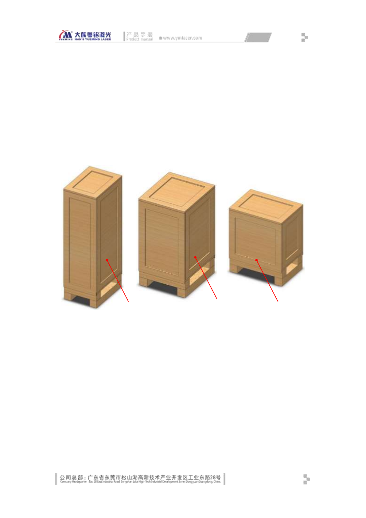
chapter3. Equipment Installation and
① Base packing case
② Control cabinet packing
③ Workbench packing case
①
②
③
Commissioning
3.1 Equipment Installation
3.1.1.1 Unpacking Steps
Before installation, disassemble the wooden for the machine in the following steps:
Fig. 3-1 Equipment Packing Case
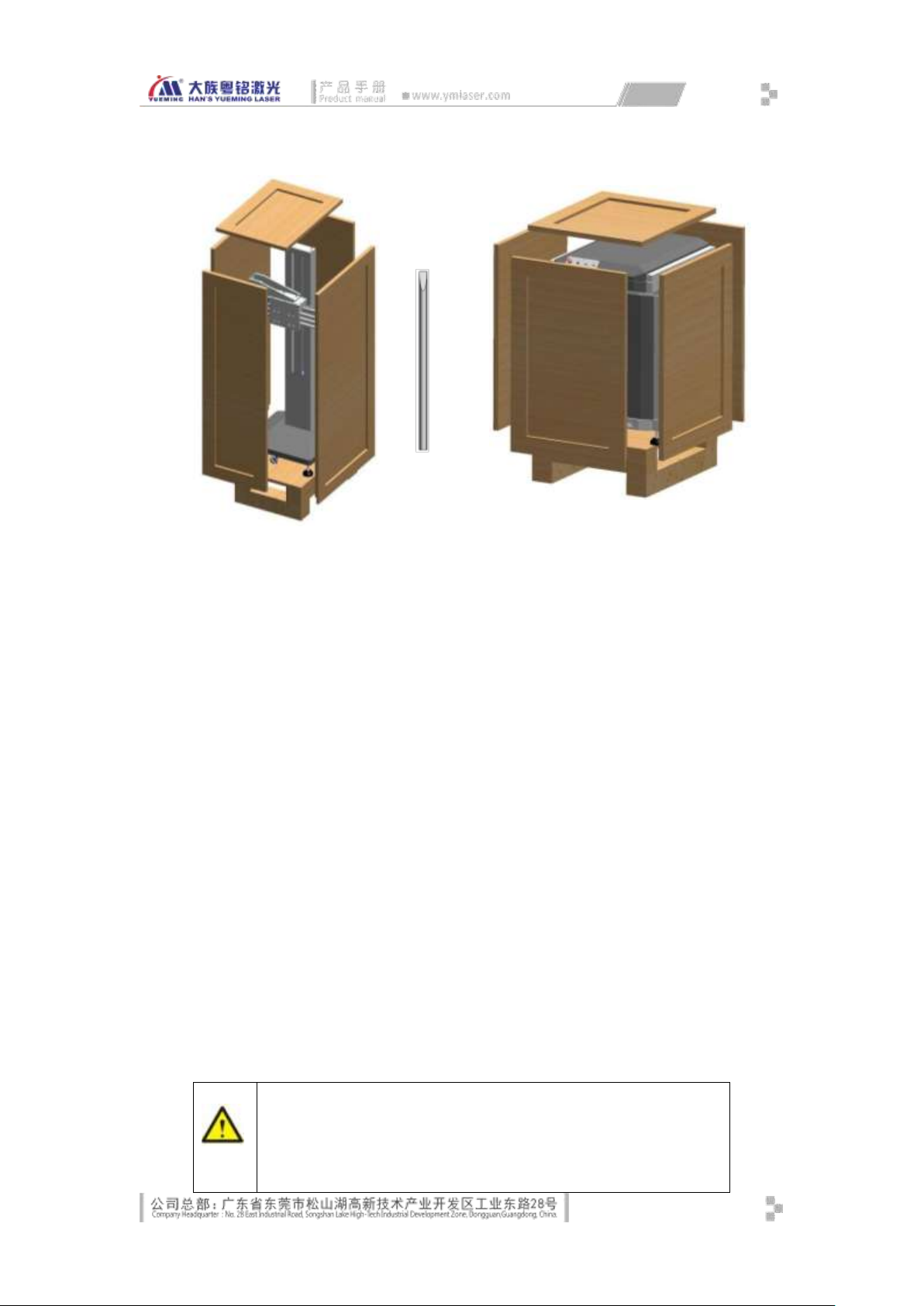
Prize up the packing case of the machine with a crowbar. Unpack in the following order:
top cover, left and right side covers, front and rear side covers, fastening ropes or fixing
plate.
19
Page 28
Note
Do not attempt to unpack without permission
If you want to unpack, first obtain the consent of our customer service or
business personnel, or else we will assume no responsibility for the
unexpected events.
Crowbar
Fig. 3-2 Machine Packing Case
Fork the machine from the pallet with a forklift with a load over 1 ton, transport to the
destination, and place in order.
3.1.1.2 Unpacking
After unpacking, check the equipment and auxiliary fittings to ensure that the product
wasn’t damaged during transport. Check the following items:
Equipment model
Please confirm that the equipment model is the one you ordered.
Appearance
Please check if the appearance has scratches, breakage, deformation or corrosion.
Chassis
Open the top cover, left and right cover, and check if the equipment has detached parts,
thread or internal damage.
Spare parts and accessories
Open the packing case of auxiliary machine, check the parts and accessories according to
the packing list, and check if the parts are damaged or deformed.
20
Page 29
Note
If any problem occurs after unpacking, please inform our
customer service or business personnel, or call the company
directly
Do not attempt to handle without permission
Note
The customer shall accompany in the whole course when the customer service
personnel install the equipment. The installation and commissioning are part of
the training, and the user shall master.
3.1.1.3 Preparation
The preparations required before installation are as follows:
Site
Please check if the site conditions and working environment for the laser equipment
comply with the requirements in Section 1.4 and the requirements of our company.
Personnel
The equipment must be installed by our professional service personnel. If the customer
wants to install the machine, the installer must have received the full installation training
and have mastered the key points of laser equipment installation.
Tools
The installation tools have been provided. In addition, the user should prepare some
installation and testing tools if necessary, such as screwdrivers, multimeter, etc.
Others
The user needs to prepare the water, electricity, smoke exhaust channels, proofing
materials, computer and power outlets associated with the equipment.
3.1.2 Installation Steps
3.1.2.1 Installing Fiber Laser Marking Cavity
Take out the fiber marking cavity embedded in the control cabinet, and fix it on the
rotating plate of the base with four M5 hexagon socket screws, as shown in Fig. 3-3:
21
Page 30

Fig. 3-3 Installation and Fixation Diagram of Fiber Marking Cavity
3.1.2.2 Installing Computer, Keyboard & Mouse
Take out the computer, open the front door of the control cabinet, insert the computer
into the guide slot, and insert the 3-pin power cord plug into the power port of the
computer.
Take out the monitor, snap in the monitor base, place on the control cabinet, connect
the video cable to the host, and insert the 3-pin power cord plug into the power port.
Take out the mouse and keyboard, put in the corresponding position and insert the
cords into the mouse and keyboard ports respectively.
Connect the USB cable of the control card to the USB port of the host computer.
3.1.2.3 Installing Scanning Focus Lens
Take out the optical scanning focus lens carefully from the packaging case, remove the
protective plastic cover, and screw the threaded end of the lens gently into the field
lens ring in the marking head. In the installation process, do not touch the lens with
hands or other objects to ensure clean and avoid damage.
22
Page 31
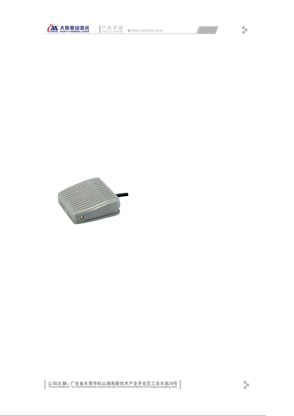
Fig. 3-4 Scanning Focus Lens Installation Diagram
3.1.2.4 Connecting Galvanometer Cable
Insert the galvanometer signal cable DB15-pin rectangular connector to the marking
control card CON1 [TO Scanhead] hole rectangular connector in the electric control
board.
Insert the galvanometer power cord with 4-hole circular connector into the
[Galvanometer Power] circular connector socket on the electrical control box, and fix.
3.1.2.5 Installing Footswitch
Place the foot switch in the lower side of the machine in order for the operator to
trigger the processing with foot, as shown in Fig. 3-5:
Connect the foot switch cable to the aviation plug socket of the [Footswitch input] of
the machine.
Fig. 3-5 Footswitch
3.1.2.6 Installing Sensor and Encoder (marking on the fly optional)
Fix the encoder on the assembly line in accordance with the mechanical installation
requirements, and connect the 6-hole circular connector plug to the circular connector
socket identified as [encoder] on the console, and fix.
Fix the sensor on the assembly line in accordance with the mechanical installation
requirements, connect the 4-hole circular connector plug to the circular connector
socket identified as [sensor] on the console, and fix; then, adjust the sensor testing
height and sensitivity according to the surface of customer workpiece.
3.1.2.7 Equipment Grounding
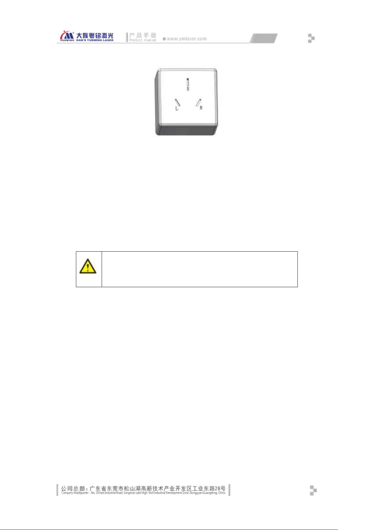
MF20 laser equipment has strict requirements on safe grounding of user power system,
which must comply with local safety standards:
23
Page 32
Note
Improper grounding can cause high failure rate, and may lead to other accidents!
The Company assumes no responsibility and obligation for such failures and
accidents
Fig. 3-6
L: 220V mains system phase line; must be equipped with safety electrical switch
(switch must be installed in the phase line).
N: commonly known as the neutral line, supply power to the equipment with the phase
line.
E: earth wire; the enclosures (earth terminals) of all electrical equipment are
connected to this wire to ensure safety. Resistance to earth should be less than 5Ω.
The user must consult professional electrical installer (electrician), and ask the electrician to
check and ensure that the earth wire is securely connected!
If the power supply system does not have earth wire, ask the electrician to install grounding
grid according to the following method:
The grounding device must be knocked into a humid place around the house with 2-4
pieces of 4×35×1500mm angle steel, the distance between each other is 1m, then lead
each piece of angle steel out of the earth with 3×30mm flat iron and form a grounding
grid.
Lay the ground grid properly, and measure its resistance to ground with the instrument
(standard resistance: 3-5 ohms).
The machine is equipped with a piece of RVV2.5mm
2
yellow-green copper wire, of
which one end is connected to the grounding line terminal and the other end is
connected to the earth wire of the etching machine, as shown below:
24
Page 33
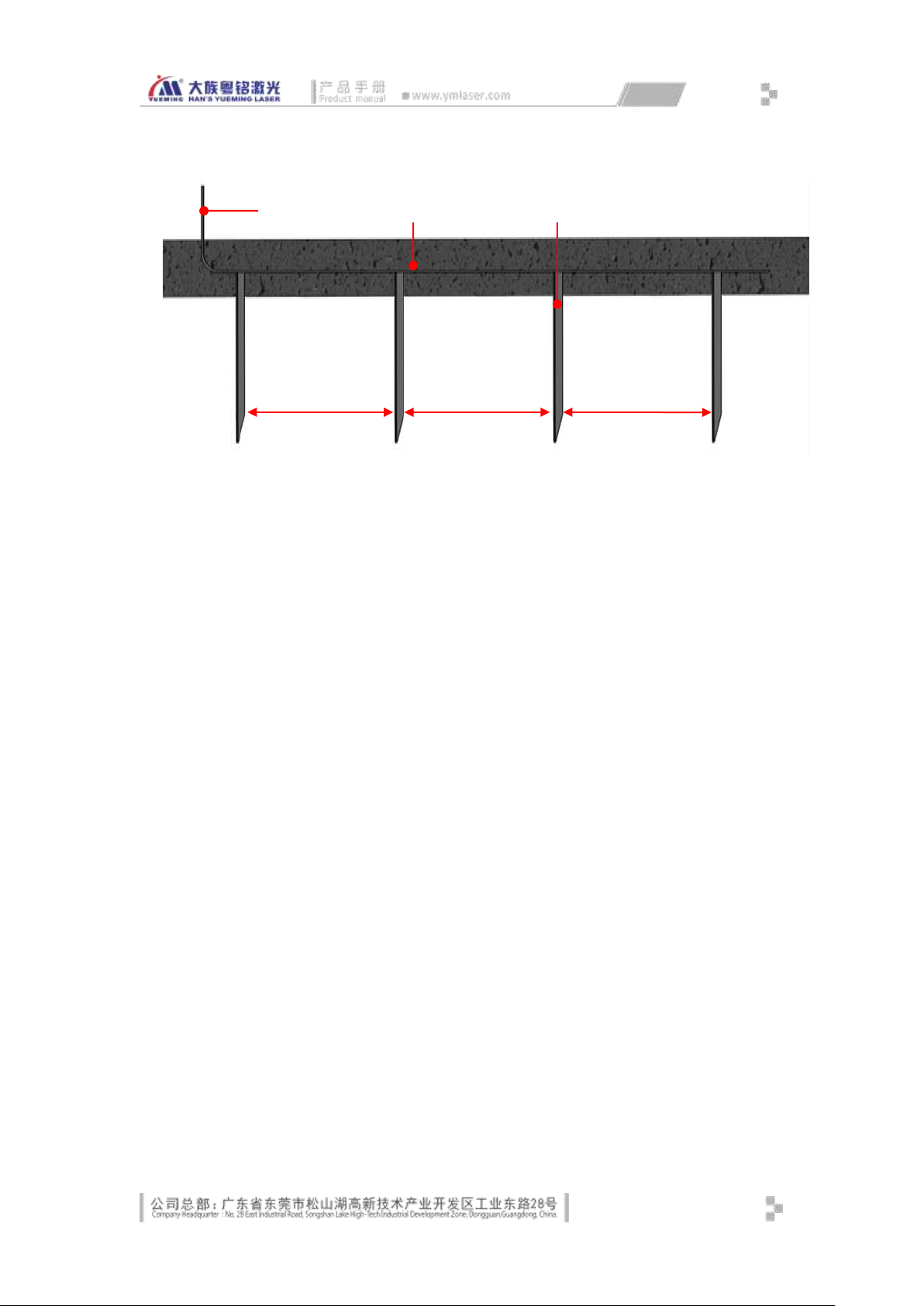
① 3*30 FLAT STEEL ② GROUND ③ 4*35*1500 ANGLE STEEL
①
③
②
1m
1m
1m
Fig. 3-7 Equipment Grounding Diagram
25
Page 34
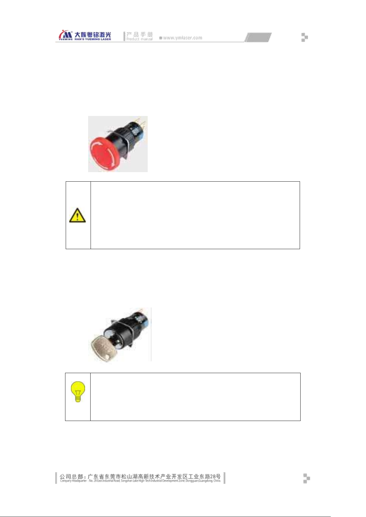
3.2 Buttons and Indicators Description
Note
Press the emergency stop button, the system will only prohibit scanning
galvanometer marking and laser light emission, and the main circuit and control
circuit won’t be turned off. To cut off the power of the machine where necessary,
turn off the main power switch off and unplug the power cord.
Release the emergency stop button and continue to operate the machine only
when emergency situations have been eliminated and all defects have been
corrected or repaired.
Prompt
Only when the key switch is turned on, the galvanometer and the laser
will power on and work; the cooling fan will energize and dissipate heat.
The power of the computer and the monitor is not controlled by this key
switch.
Emergency stop button
Emergency stop button is mounted in the first hole on the control panel. When there is an
emergency, press this button, the system will stop marking processing and light emission.
Key switch (main power)
Key switch is mounted in the second hole on the control panel. When the key switch is
rotated 90 degrees clockwise, the main loop powers on, when the key switch is rotated 90
degrees counterclockwise, the main loop powers off.
Self-locking illuminated button (galvanometer)
26
Page 35
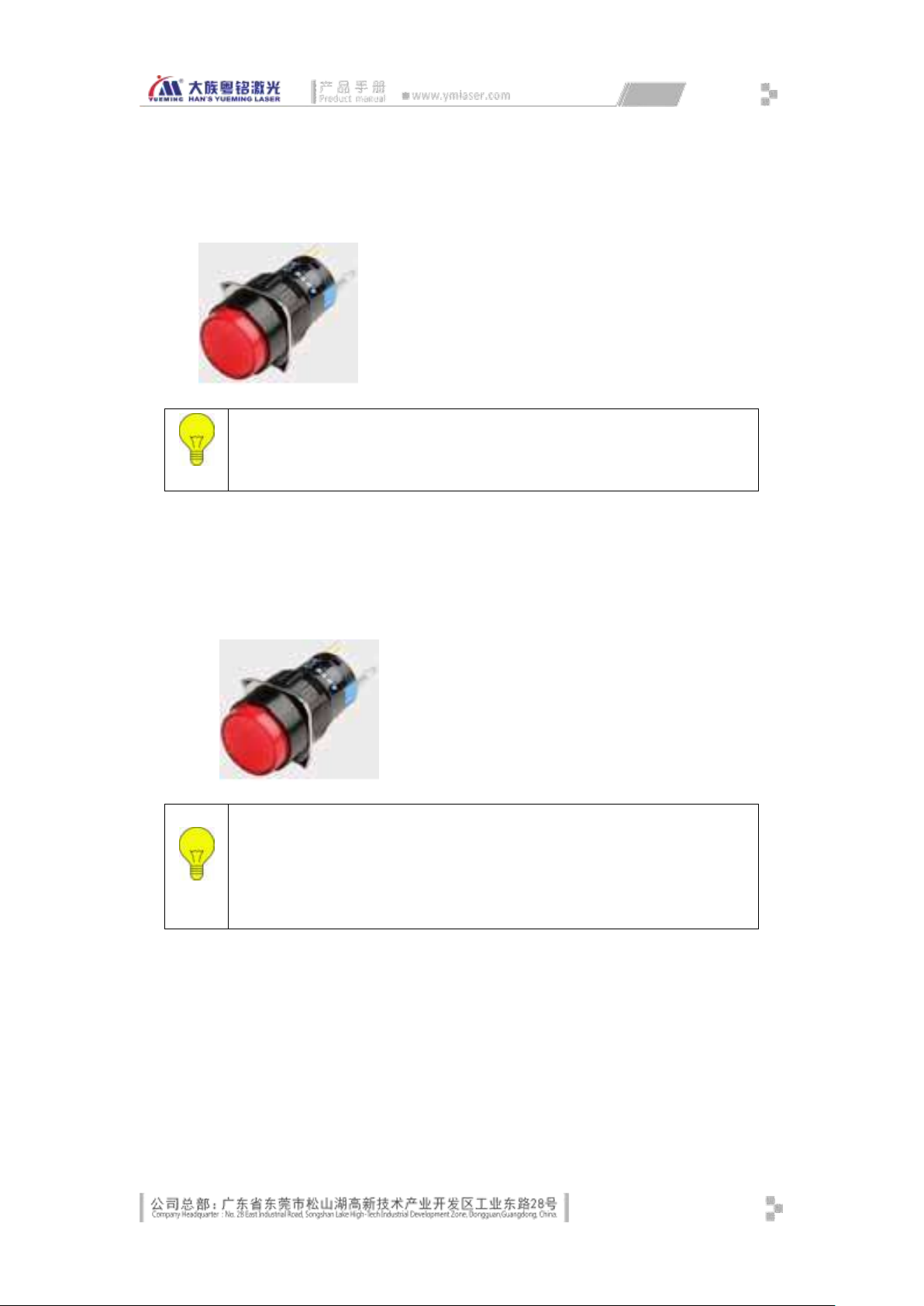
Self-locking illuminated button (galvanometer) is mounted in the third hole on the control
Prompt
To examine the galvanometer or check the scanning lens surface, turn
off this button.
Prompt
When the laser powers on, wait 7-8 seconds to let the laser initialize.
After power on, the laser is in emission ready state. Be careful to avoid
emission due to misuse and result in personal injury and product
damage
panel. When you press this button, the galvanometer powers on, the built-in LED turns to
red, and the scanning lens automatically returns to zero.
Self-locking illuminated button (laser)
Self-locking illuminated button (laser) is mounted in the fourth hole on the control panel.
When you press this button, the laser powers on, the built-in LED turns to red, and the
internal cooling fan of the laser starts working.
3.2.1 Installing Other Accessories
Some models also come with other accessories and should be installed by our customer
service personnel. In addition, the optional scanner, printer and other equipment should be
installed by the customer.
27
Page 36

3.3 Equipment Debugging
3.3.1 Switch sequence
After installation, equipment commissioning and processing test should be done.
Switch sequence
The sequence of switching on:
Circuit breaker -> computer / monitor power -> galvanometer power -> laser power -> other
auxiliary equipment.
The sequence of switching off:
Other auxiliary equipment -> laser power -> galvanometer off -> computer -> circuit
breaker.
3.3.2 Galvanometer Marking Test
Open the marking software, and draw a simple graphics, such as rectangle. Set the
appropriate parameters and click [Preview], the laser emits red light, which is scanned into red
rectangle box consistent with the graphics by the scanning galvanometer, indicating that the
galvanometer scanning is normal. If the galvanometer has transition, sawtooth, lack of edge or
deformation, immediately turn off the galvanometer power, and check the failure.
3.3.3 Laser Test
Open the marking software, and draw a simple graphics, such as rectangle. Put the metal
surface material below the optical scanning lens, click [Mark] and the laser emits laser, adjust the
handwheel to factory working distance, laser acts on the metal material, and emits light and
sparks, accompanied by marking sound. Adjust the power value to change the laser energy;
adjust the frequency value to change the laser energy and the sound effect on the material. Test
if the laser is normal in the above method. If the laser can’t emit light, check if the power is
normal, if the wiring is loose, if the emergency stop has been pressed, if the parameters are
correct, and if in the focal length.
3.3.4 IO Test
Connect the footswitch, step on lightly and check if the marking software triggers
marking; if not, check if the wiring is loose and if the marking port is correct.
Draw a graphics and test the marking. In the normal marking process, press the
emergency stop button and check if the emission and marking stop. If not, check if the
wiring is loose and if the corresponding IO port is correct.
Above are the basic processing steps; for specific operation, refer to the host software
manual.
28
Page 37

3.3.5 Sensor and Encoder Test (optional)
After connecting the sensor cable, open the marking software, draw a graphics, set the
appropriate parameters, check Continuous Marking, click [Mark], sway under the
sensor with the object, check if the software triggers marking; if not, check if the wiring
is loose, if the port settings are correct, if the sensor test height is correct, and if the
sensor sensitivity is appropriate.
After connecting the encoder cable, open the marking software, open marking on the
fly dialog box, check and set the appropriate parameters, start the assembly line work,
and check if the line body speed is displayed on the marking on the fly dialog correctly.
If not, check if the wiring is loose, if the parameters are set correctly, if the fly system is
correct, synchronization between encoder and assembly line, and if contact between
the encoder wheel and the assembly line is too tight or too loose.
29
Page 38

chapter4. System Maintenance
The stable and normal working of the machine depends on the correct operation and
routine maintenance. This chapter describes the daily maintenance of the equipment.
4.1 Mechanical Maintenance
The mechanical design of this machine is designed in the concept of 10 years
maintenance-free.
If mechanical failure is caused by unpredictable external factors, please contact the
manufacturer.
4.2 Electrical Maintenance
The electrical maintenance mainly includes electrical components, buttons, marking control
card, and sensors.
Regularly check if the power indicator of the electrical box switch is normal, if the
wiring is loose, if the cable is aging, if the output voltage meets the specifications,
check the heat dissipation, if there is contamination or blockage, and resolve in
sequence.
Regularly check the contact sticking of the intermediate relay, if the wiring is loose and
if the indicator is normal.
Regularly check the air volume of the cooling fan is normal, if the speed is normal, if
there is abnormal sound, if there is contamination or blockage, and resolve in
sequence.
Regularly check if the marking control card LED is normal, if the chip cooling is in
reasonable limit, if the connector is loose, if PCB is contaminated and resolve in
sequence.
Regularly check if the sensor fiber optic cable has any mechanical or corrosion damage,
if the indicator is correct, if fiber head is contaminated and resolve in sequence.
Regularly check the computer and monitor hardware maintenance and system
maintenance to ensure the normal operation of the software.
4.3 Maintenance of Optical Path and Optical Devices
The optical system of the fiber laser marking machine consists of fiber laser, optical
scanning galvanometer and optical scanning field lens.
It is inevitable for the optical element to contact with the suspensions when the laser is
operating. When the laser is cutting, engraving or marking the material, the build surface will
30
Page 39

release a lot of gas and splashes, which will damage the lens. When the contaminant falls on the
lens surface, it will absorb energy from the laser beam, resulting in thermal lens effect. If the lens
hasn’t formed thermal stress, the operator can disassemble and clean it. The method should
avoid damage to the lens and further contamination.
General Operation Principles
In the installation and cleaning process of lens, any sticky material, even nail print or oil
droplets, will increase the absorption rate of the lens and reduce service life.
Therefore, the following precautions are required:
Do not use suction device or inflatable equipment to avoid scratching the lens
surface;
Hold the edge of the lens rather than the film when take lens;
The lens should be stored in a dry and clean place for testing and cleaning. A good
console should have several layers of cleaning tissue or lens tissue on the surface;
The operator should avoid talking over the lens, and keep food, beverages and
other potential contaminants away from the working environment.
The correct cleaning method
In the process of cleaning the lens, the only purpose is to remove the contaminants, and
avoid further contamination and damage. To achieve this goal, people tend to use an approach
with relatively small risk. The following procedure is established for this purpose.
First, first blow the floating material off the lens surface with air ball, particularly the fine
particles and wadding material on the lens surface. But do not use compressed air on the
production line, because the air will contain oil and water droplets, which will deepen the lens
contamination.
Secondly, clean the lens with acetone or anhydrous alcohol (reduce the possibility of lens
contamination)
Dip the lens paper in acetone and clean the lens in the light, and move circularly. Once the
lens paper is dirty, it must be replaced. The cleaning must be finished in one time to avoid
scratching.
Some contaminants and lens damage can’t be removed by washing, for example, film burn
due to dirt, stripping caused by condensation. In order to restore perfect performance, the only
way is to replace the lens.
31
Page 40

4.4 Auxiliary Machine Maintenance
No related auxiliary machine maintenance is available. If any auxiliary machine is optional,
follow the technical description of the auxiliary machine for maintenance.
32
Page 41
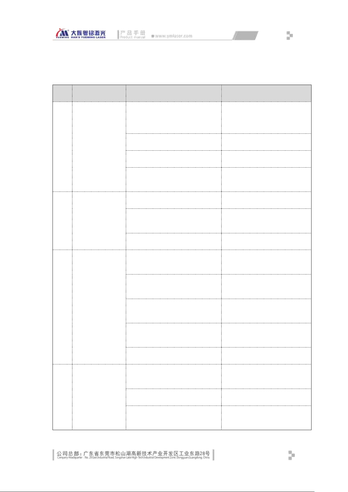
chapter5. Troubleshooting
No.
Failure
Reason
Solution
1
Can’t turn on the
equipment
The circuit breaker in the
electrical control box isn’t turned
on
Turn on the circuit breaker
Key switch is damaged
Replace the key switch
Intermediate relay is damaged
Replace the intermediate relay
System short circuit
Check and repair the short
circuit
2
Can’t turn on the
laser /
galvanometer
Control button is damaged
Replace the control button
Control switching power supply is
damaged
Replace the switching power
supply of same model
Intermediate relay is damaged
Replace the intermediate relay
3
Can’t find the
control card
External switching power supply
is damaged
Replace the switching power
supply
Control card power cord plug is
loose
Reseat connector plug
USB cable isn’t plugged in
properly
Reinsert the USB cable properly
Driver is uninstalled or not
installed
Reinstall the driver
Control card is damaged
Replace the control card
4
Marking graph
deformed
Correction parameter is incorrect
Modify the correction
parameters
Scale is incorrect
Modify the scale parameter
Galvanometer signal cable isn’t
plugged in properly
Check the signal cable interface
and plug properly
33
Page 42

5
No laser ray
Laser control plug isn’t plugged
in properly
Insert laser control plug properly
Laser switching power supply is
damaged
Replace the switching power
supply
Laser heat dissipation poor
Check the operation of the
cooling fan
Laser failure
Replace or repair the laser
34
Page 43
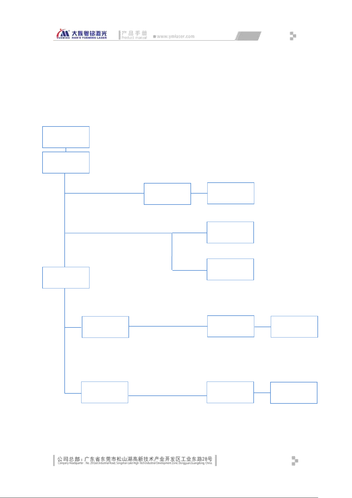
Appendix
Scanning
galvanometer
Control card &
control loop
AC220V 50HZ
Main power
switch
Switching
power supply
Switching
power supply
Intermediate
relay
Intermediate
relay
Intermediate
relay
Switching
power supply
Appendix 1 Electrical Control System Block Diagram of Main
Power
5.1.1
Computer
Monitor
Fiber laser
35
Page 44

Post
Final explanation right belongs to Hans YueMing Laser Technology Co. Ltd of GuangDong.
We reserve the right to make changes on our machines without notice to users.
The above icon is the registered trademark of Hans YueMing Company.
Copyrights belong to Hans YueMing Tech. Co. Ltd. It is forbidden to pirate or copy any part
of our machines without our permission. Violators will be prosecuted to the full extent of
applicable law.
07020101000
RMB:50.00
32
 Loading...