

Page 1
1
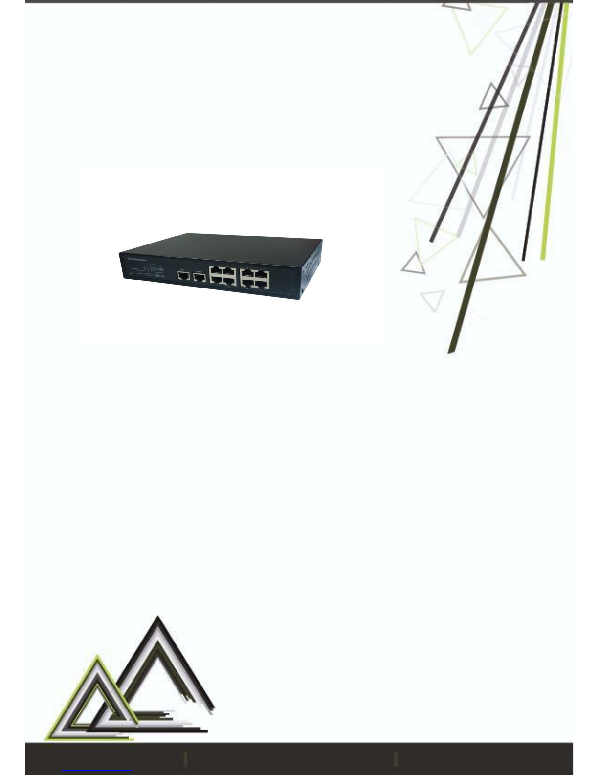
4/8 CHANNELS
SMART PoE SWITCH
V1.0_1608
User Manual
Page 2
2
Preface
Smart PoE Switch is designed to enhance a more convenient RJ45 internet
connection with network devices without having to establish extra power
connection. It is a PoE switch that comes with smart features. The user can
configure settings including User management, Port Management, VLAN
Setting, Per Port Counter, QoS setting, Security, Spanning Tree, Trunking,
DHCP Relay Agent, Backup/Recovery, Miscellaneous, SNMP Settings, Logout,
and so on
Enter the Configuration Page
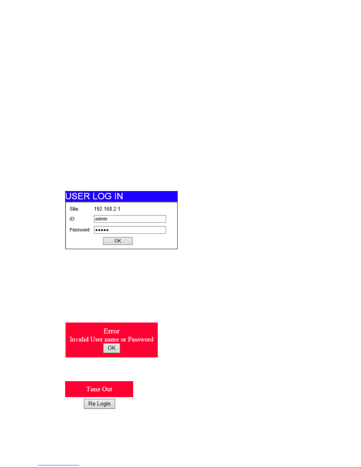
Enter the correct administrator name and password after the login page shows up.
Default IP address: 192.168.2.1
Default administrator name: admin
Default password: admin
Press “OK” to login.
Note: the administrator name and password fields are case-sensitive. The
higher case characters will be recognized as different characters. For example:
“ADMIN” will be recognized as the different character from “admin”.
If you input the incorrect administrator name or password, the following
warning message will show up and you must click “OK” to go back to the login
page.
The system will require the user to login again if it is left unoccupied.
Page 3

3
i. Specification …………………………...........................................................5
ii. Hardware Overview …...............................................................................6
* Front Panel (4-port) .............................................................................6
* Front Panel (8-port) .............................................................................6
* Back Panel ….......................................................................................7
iii. Administrator ……......................................................................................7
* Authentication Configuration ............................................................7
* System IP Configuration .....................................................................7
* System Status .......................................................................................8
* Load default setting ............................................................................8
* Firmware Update ................................................................................8
* Reboot Device ....................................................................................9
iv. PoE .............................................................................................................9
* PoE Status .............................................................................................9
* PoE Setting …………...........................................................................10
* PoE Event Counter .............................................................................11
* PoE Power Delay ...............................................................................11
* PoE Scheduling .................................................................................12
* PoE Auto Check ................................................................................12
* NTP Setting .........................................................................................13
v. Port Management ...................................................................................14
* Port Configuration .............................................................................14
* Port Mirroring .....................................................................................14
* Bandwidth Control ............................................................................15
* Broadcast Storm Control ..................................................................17
vi. VLAN Setting ………………......................................................................18
* VLAN mode .......................................................................................18
* VLAN Member Setting ......................................................................19
* Multi-to-1 Setting ...............................................................................21
* Non-Association Port Setting ...........................................................22
vii. Per Port Counter .....................................................................................22
Page 4

4
viii. QoS setting ............................................................................................23
* Priority Mode .....................................................................................23
* Class of Service Configuration ........................................................24
* Class of Service .................................................................................24
ix. Security ....................................................................................................26
* MAC Address Binding .......................................................................26
* TCP/UDP Filter ....................................................................................27
x. Spanning Tree ..........................................................................................28
* STP Bridge Settings ............................................................................28
* STP Port Settings .................................................................................29
* Loopback Detection Settings ..........................................................30
xi. Trunking ...................................................................................................31
xii. DHCP Relay Agent .................................................................................32
* Relay Agent Configuration ..............................................................32
* Server IP List .......................................................................................33
* VLAN to Server IP Map ......................................................................33
xiii. Backup/Recovery ................................................................................33
xiv. Miscellaneous Settings .........................................................................34
* Output Queue Aging Time ...............................................................35
* VLAN Striding .....................................................................................35
* IGMP Snooping .................................................................................35
* VLAN Uplink .......................................................................................35
xv. SNMP Settings .........................................................................................36
xvi. Logout ....................................................................................................37
xvii. Load Default Setting – Hardware Based ............................................37
Page 5

5
4-port:
8-port:
1 x 10/100/1000 BaseT RJ45 ports
2 x 10/100/1000 BaseT RJ45 ports
Support 802.3at PoE supply
Power isolation to ensure the equipment stability
Working temperature: -20~60℃
Semi-industrial: working temperature -20~60℃
Plug& play with smart NVR series
Management functions
Hardware Interface
RJ45 Port
4 port 10/100BaseT with PSE
1 port 10/100/1000BaseT(X)
8 port 10/100BaseT with PSE
2 port 10/100/1000BaseT(X)
Led Indicator
Ethernet Link/Act ; PoE Status
Communications
Standards
IEEE 802.3 10BaseT; IEEE 802.3u 100BaseTX
IEEE 802.ab 1000BaseT; IEEE 802.3x Flow Control
IEEE 802.3at Power Over Ethernet (PoE+)
IEEE 802.3ad Link Aggregation Control Protocol
IEEE 802.1p Class of Service; IEEE 802.1Q VLAN
Transmission Data
10BaseT Cat. 3, 4, 5 UTP/STP; 100BaseTX Cat. 5 UTP/STP
1000BaseT Cat. 5/5E,6 UTP/STP
Power
Power Output
PoE 802.3at compliant
30W Max. per Port
Total PoE power output
capacity: 60W
PoE 802.3at compliant
30W Max. per Port
Total PoE power output
capacity: 120W
Power Input
100~240V/AC, 50~60Hz
Network management
Security
MAC Address Binding, TCP/UDP Filter
VLAN
802.1Q Tagged based, Port based
Traffic control
IGMP Snooping, Port Trunk, QoS/CoS (TCP/UDP port number,
IP TOS/DS, 802.1p priority tag and physical port)
Environment
Operating Temperature
-20 ~ 60℃
Humidity
0~80% RH (Non-condensing)
Dimension (W x H x D)
219x44x159 mm
Weight
1150g
i. Specification
Page 6
6
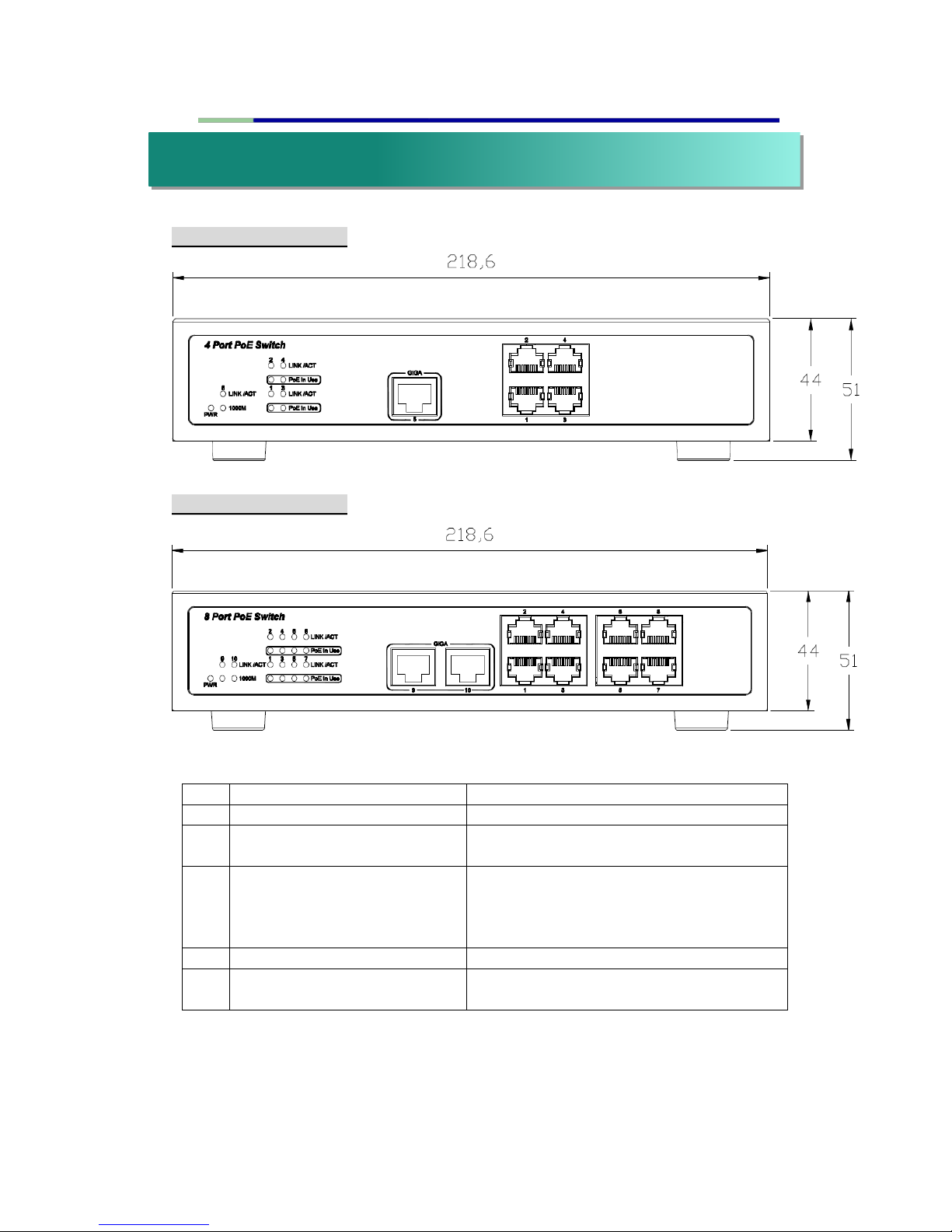
* Front Panel (4-port)
* Front Panel (8-port)
NO.
LABEL
OPERATION
1
PWR
Power Supply Status indicator
2
LINK/ACT 1~4/1~8 PoE In
Use
Ethernet Link/Act Status LED indicator
3
LINK/ACT 5/9,10 1000M
(Gigabit)
Ethernet Connection Status LED
indicator for PC/LAN. Upper LED glows
for 10/100M connection, lower LED
glows for 1000M connection.
4
GIGA 5/GIGA 9,10
RJ45 connector for PC/LAN
5
1~4
RJ45 connector for PoE (Each one
supplies up to 30w, total up to 50w)
ii. Hardware Overview
Page 7
7
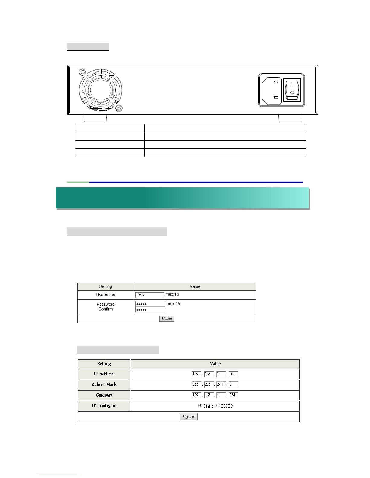
* Back Panel
LABEL
OPERATION
a
FAN
b
Power adapter (100~240V/AC) input
c
Switch button
* Authentication Configuration
This page allows the administrator to change the administrator name and
the password. You can input up to 15 characters for each field. The default
username and password is both admin. Note: The legal characters for
these fields are “a~z”, “A~Z”, “0~9”, “_“, “+”, “-”, “=”.
* System IP Configuration
iii. Administrator
a b c
Page 8
8
This page shows system configuration including the current IP address and
sub-net mask and Gateway. IP address, Subnet Mask, and Gateway at
system IP Configuration can be configured by the administrator. The smart
switch also supports DHCP method to allow the dynamic IP address
allocated by DHCP server.
* System Status
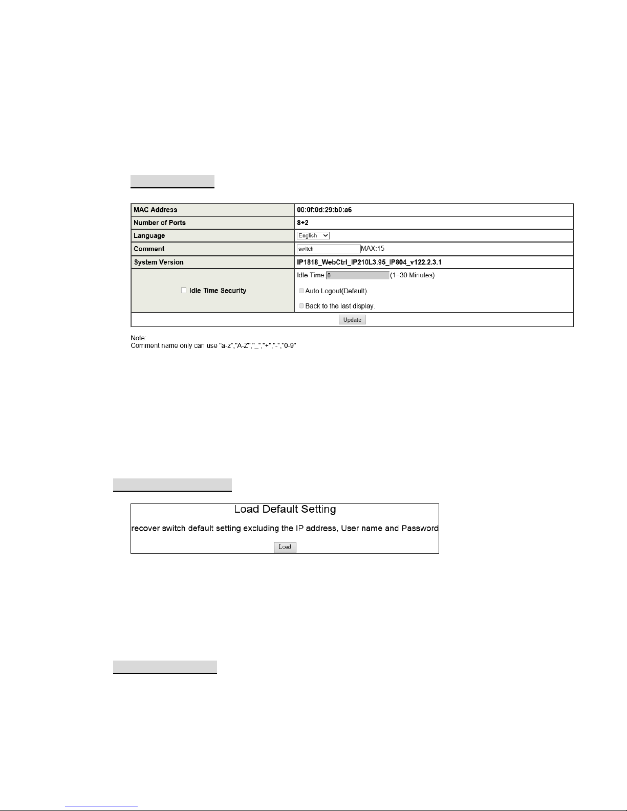
This page allows the administrator to check the status of switch, including switch
MAC address and software version. The comment field allows the network
administrator to input an easy-to-remember nickname for this switch. The legal
characters are “a~z”, “A~Z”, “0~9”, “_“, “+”, “-”, “=”, excluding special character.
The Idle time field allows the administrator to set a timer for auto logout. When the
system detects no web page activity for a pre-defined time, it will auto-logout.
* Load default setting
Clicking the “Load” button will make the switch go back to the original
configuration.
Note: this change only concerns the switch behavior, excluding the change
for IP Address, User Name and password. After Load Default is executed,
the all settings will be restored to default setting.
* Firmware Update
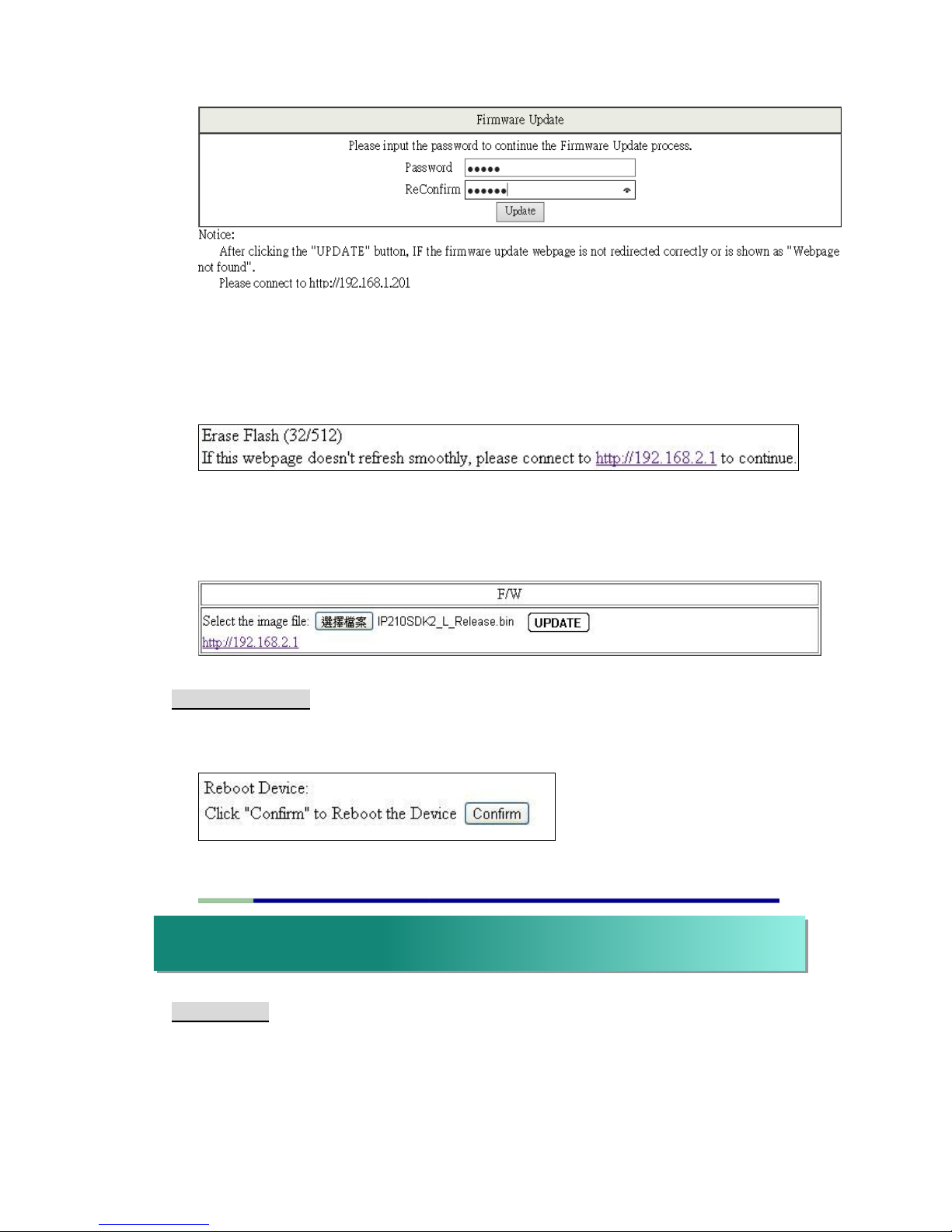
Before the firmware update procedure is executed, you should enter the
login password twice and then press “Update” button.
Page 9
9
There is a self-protection mechanism in the BootLoader, so the BootLoader
will keep intact. Even though the power is turned off or the cable link fails
during the firmware update procedure, the BootLoader will restore the code
to firmware update page.
After you press “Update” button, the old web code will be erased. After
completing, you should select the image file and press “Update” button to
take effect.
* Reboot Device
This page is used to reboot device. No hardware reset is executed by
means of executing “Reboot Device”.
* PoE Status
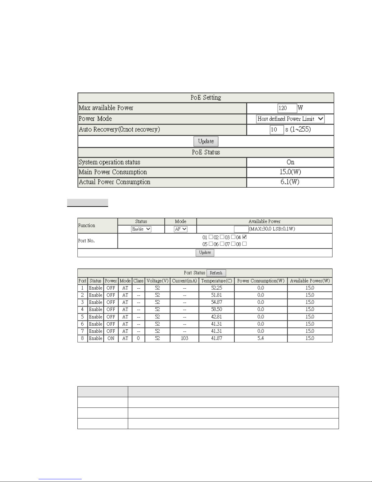
This page allows the administrator to check PoE status of this Switch,
including Max available Power, System operation status, Main Power
Consumption and all Device Temperature.
iv. PoE
Page 10
10
The Max available Power field allows the administrator to input a number of
maximum available power supply of all PSE device for this Switch.
Numbers available from “0” to “999” watts depend on the power supplies
capability. If power consumption reaches this threshold, the lowest priority
ports will be disconnected.
* PoE Setting
This page allows the administrator to configure PoE setting of the physical port.
After selecting the settings, you should press “Update” button to take effect.
The setting will be reflected at Port Status window.
Field
Description
Status
Set all ports enable or disable PoE feature.
Mode
Supports both 802.3at and 802.3af.
Power Budget
Set all ports power supplies watts, the maximum watts is “36W”.
Page 11
11
* PoE Event Counter
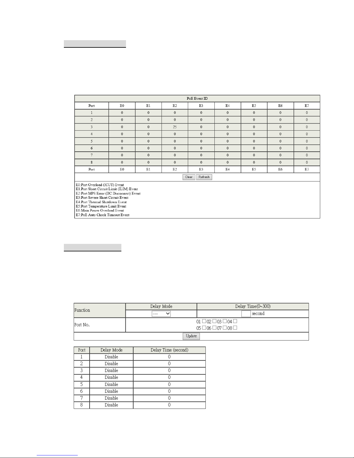
This page manages to display how many times a digital signal is counted
when its state changes. Any error event will also be recorded and displayed
in this page. The user can identify the type of signal according to the event
ID type explained below.
* PoE Power Delay
This page allows the administrator to configure the PoE power delay time
for all physical ports in the Switch boot. After selecting the settings, you
should press “Update” button to take effect. The setting will be reflected at
the following window.
Page 12
12
Field
Description
Delay Mode
Set all ports enable or disable power delay feature.
Delay Time
Set all ports power supplies delay time. This delay time
is counted starting from the Switch boot. When the port
is enabled this function and delay time is up, the PSW
will begin supplies power.
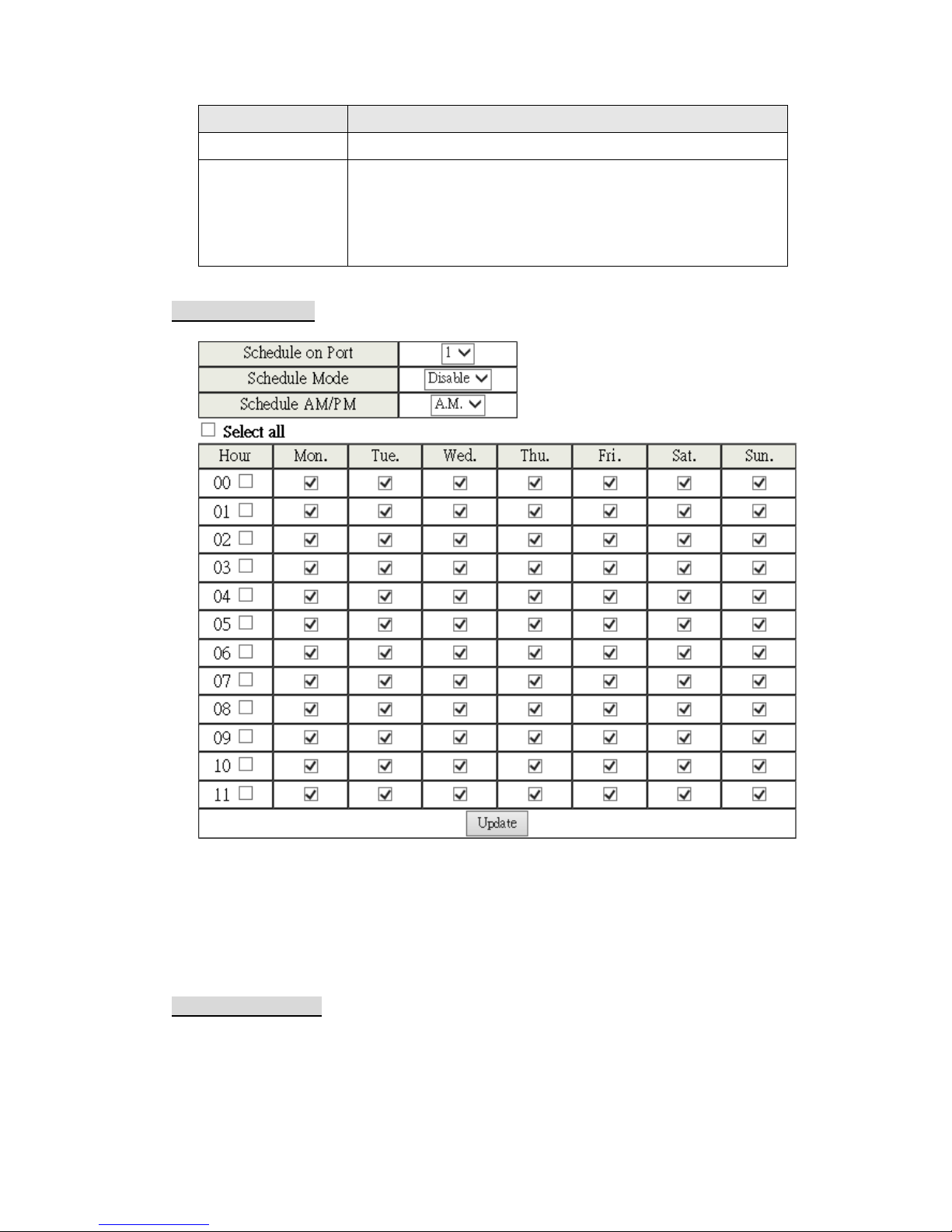
* PoE Scheduling
This page allows the administrator to configure schedule to begin supplies
power of the PSE for all physical ports. After selecting the settings, you
should press “Update” button to take effect.
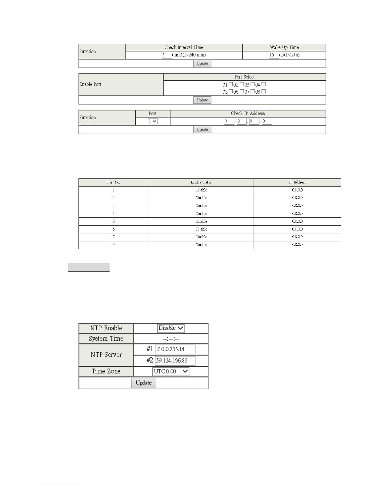
* PoE Auto Check
The user can assign the Check Interval time and Wake Up Time to each
port. Click on the checkbox of each port from Port Select section, and click
update to enable the setting.
Page 13
13
Enter the IP address of each device connected to each port in Check IP
Address field, click Update to continue check on the connecting details of
each port.
* NTP Setting
This page allows the administrator to configure NTP Server and Time Zone
to get Universal Time Coordinate. After selecting the settings, you should
press “Update” button to take effect. This time will be reflected at the
System Time window.
Page 14
14
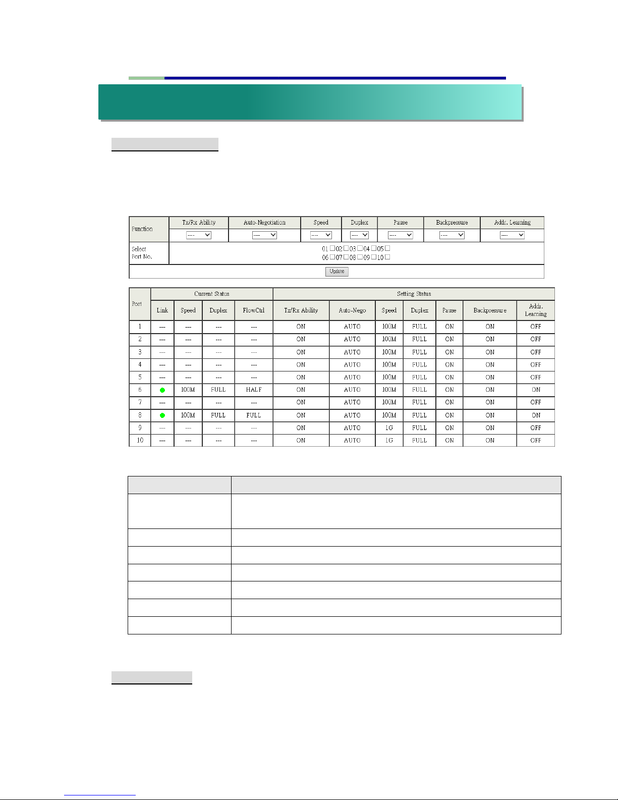
* Port Configuration
This page allows the administrator to configure operating mode of the
physical port. After selecting the settings, you should press “Update” button
to take effect. The setting will be reflected at current status window.
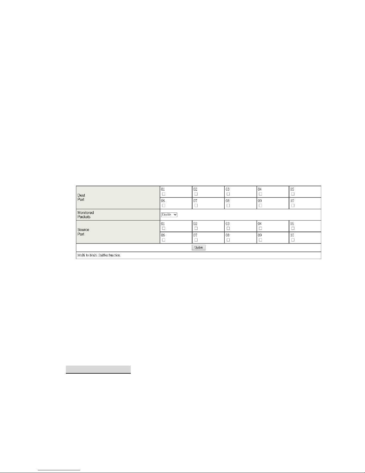
* Port Mirroring
The port mirroring function is accomplished by setting the following items.
Field
Description
Tx/Rx Ability
Enable: Set this port normal operating mode.
Disable: Shut down this port.
Auto-Negotiation
Enable/Disable Auto-negotiation.
Speed
Select 1Gbps, 100Mbps or 10Mbps
Duplex
Select Half duplex or Full duplex
Pause
Enable/Disable symmetric pause ability
Backpressure
Enable/Disable backpressure flow control in half duplex mode
Addr. Learning
Enable/Disable MAC address learning ability
v. Port Management
Page 15
15
(a) Destination port: Theoretically it’s possible to set more than one
destination port in a network. Actually the port mirroring function will
lower the network throughput, and therefore it’s recommended to
set ”only one” destination port in a network.
(b) Source port: the traffic source that will be copied to the destination port.
(c) Monitored method:
Disable: means this function is disabled.
Rx: means copy the incoming packets of the selected source port to
the selected destination port.
Tx: means copy the outgoing packets of the selected source port to
the selected destination port.
Tx & Rx: means the combination of Tx and Rx.
Take the following configuration as an example.
(a) Destination Port: Port 9 ~Port 12
(b) Source port: Port 1 ~ Port 4
(c) Mirrored method: Rx
This means all packets received at port 1 ~port 4 will be copied to port 9,
port 10, port 11 and port 12. Care should be taken that the more source
ports and destination ports is set, the lower network throughput is available
for normal traffic.
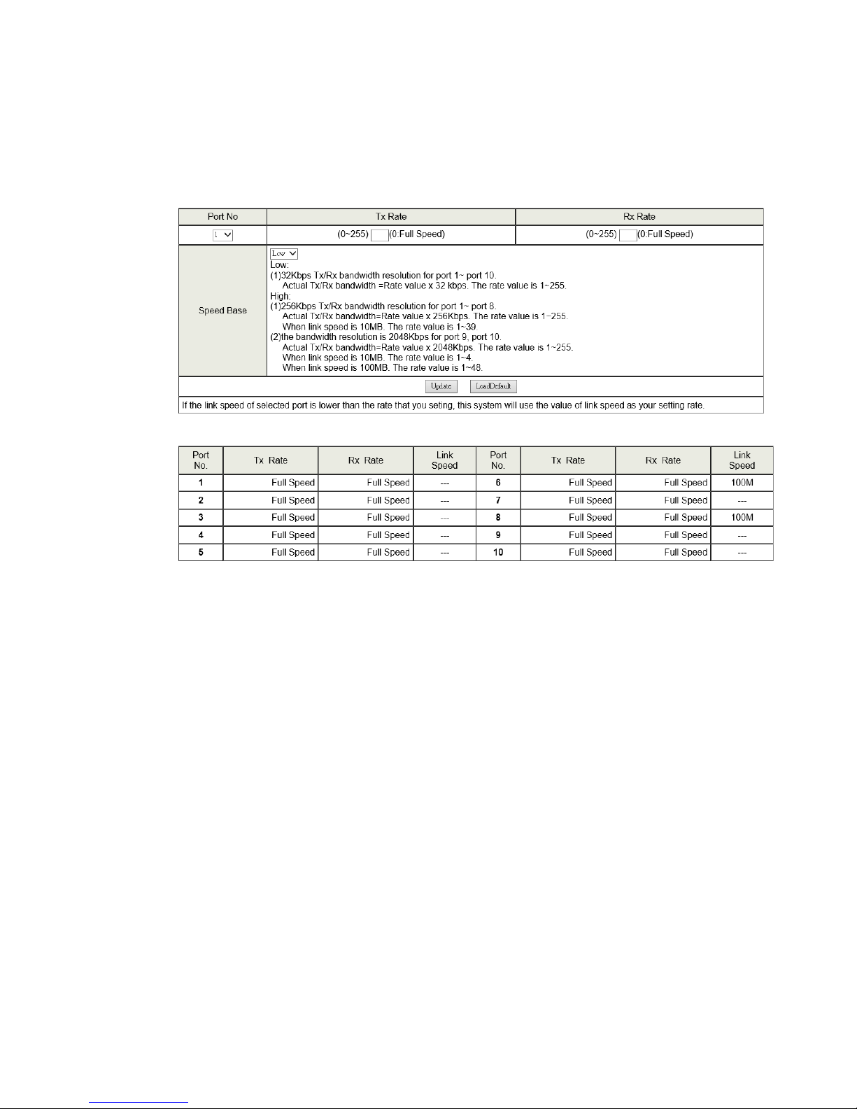
* Bandwidth Control
This page allows the setting of the bandwidth for each port. The Tx rate and
Rx rate can be filled with the number ranging from 1 to 255. This number
should be multiplied by the selected bandwidth resolution to get the actual
bandwidth.
Page 16
16
In the “Low” mode, the Tx/Rx bandwidth resolution is 32Kbps for port 1~
port 26. In the “High” mode, the Tx/Rx bandwidth resolution is 256Kbps for
port 1 ~ port 24, and 2048Kbps for port 25, port 26.
(a) Low bandwidth for TX
Example 1: The TX number of the port1~4 is set to 10, 20, 30, 40
respectively, and Speed base is set to “Low”. The real bandwidth comes
from the formula of 32Kbps*10, 32Kbps*20, 32Kbps*30 and 32Kbps*40
respectively. After the “Update” button is executed, the real bandwidth
will show up in TX fields.
(b) High bandwidth for TX
Example 2: The TX number of the port1~4 is set to 10, 20, 30, 40
respectively, and Speed base is set to “High”. The real bandwidth
comes from the formula of 256Kbps*10, 256Kbps*20, 256Kbps*30 and
256Kbps*40 respectively. After the “Update” button is executed, the real
bandwidth will show up in TX fields.
(c) Low bandwidth for Rx
Example 3: The RX bandwidth number of the port 5~ port 8 is set to 50,
60, 70, 80 respectively, and Speed base is set to “Low”. The real
bandwidth comes from the formula of 32Kbps*50, 32Kbps*60,
Page 17
17
32Kbps*70 and 32Kbps*80 respectively. After the “Update” button is
executed, the real bandwidth will show up in RX fields.
(d) High bandwidth for RX
Example 4: The RX bandwidth number of the port 5~ port 8 is set to 50,
60, 70, 80 respectively, and Speed base is set to “High”.
The real bandwidth comes from the formula of 256Kbps*50,
256Kbps*60, 256Kbps*70 and 256Kbps*80 respectively. After the
“Update” button is executed, the real bandwidth will show up in RX
fields.
The limitation of the bandwidth control
The actual bandwidth should be less than link speed of the port.
100Mbps link speed for port 25 and port 26, the bandwidth setting
should be less than 48 if the bandwidth is set to “High”. 10Mbps link
speed for port 25 and port 26, the bandwidth setting should be less
than 4 if the bandwidth base is set to “High”.
10Mbps link speed for port 1 ~ port 24, the bandwidth setting should
be less than 39 if the bandwidth base is set to “High”.
Setting the bandwidth to “0” will make the switch running at the “Full
Speed”.
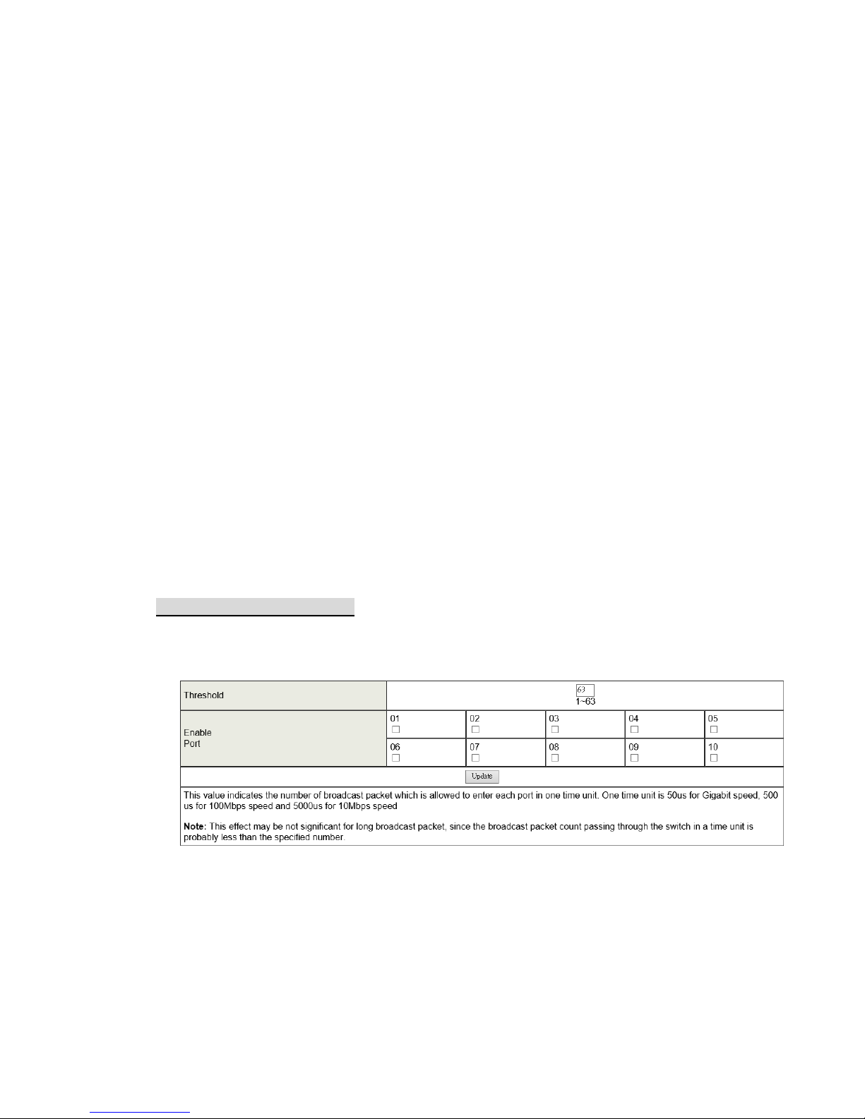
* Broadcast Storm Control
The broadcast storm control is used to block the excessive broadcast packets
received during the specified time unit. The valid number ranges from 1 to 63.
The broadcast packet is only checked at the selected port and the number
of broadcast packets is counted in every time unit.
There are 3 options for the selection of the time unit, as the figure shown
above. Once the broadcast storm protection is enabled, the excessive
broadcast packet will be discarded. For those broadcast packets incoming
from the un-selected port, the switch treats it as the normal traffic.
Page 18
18
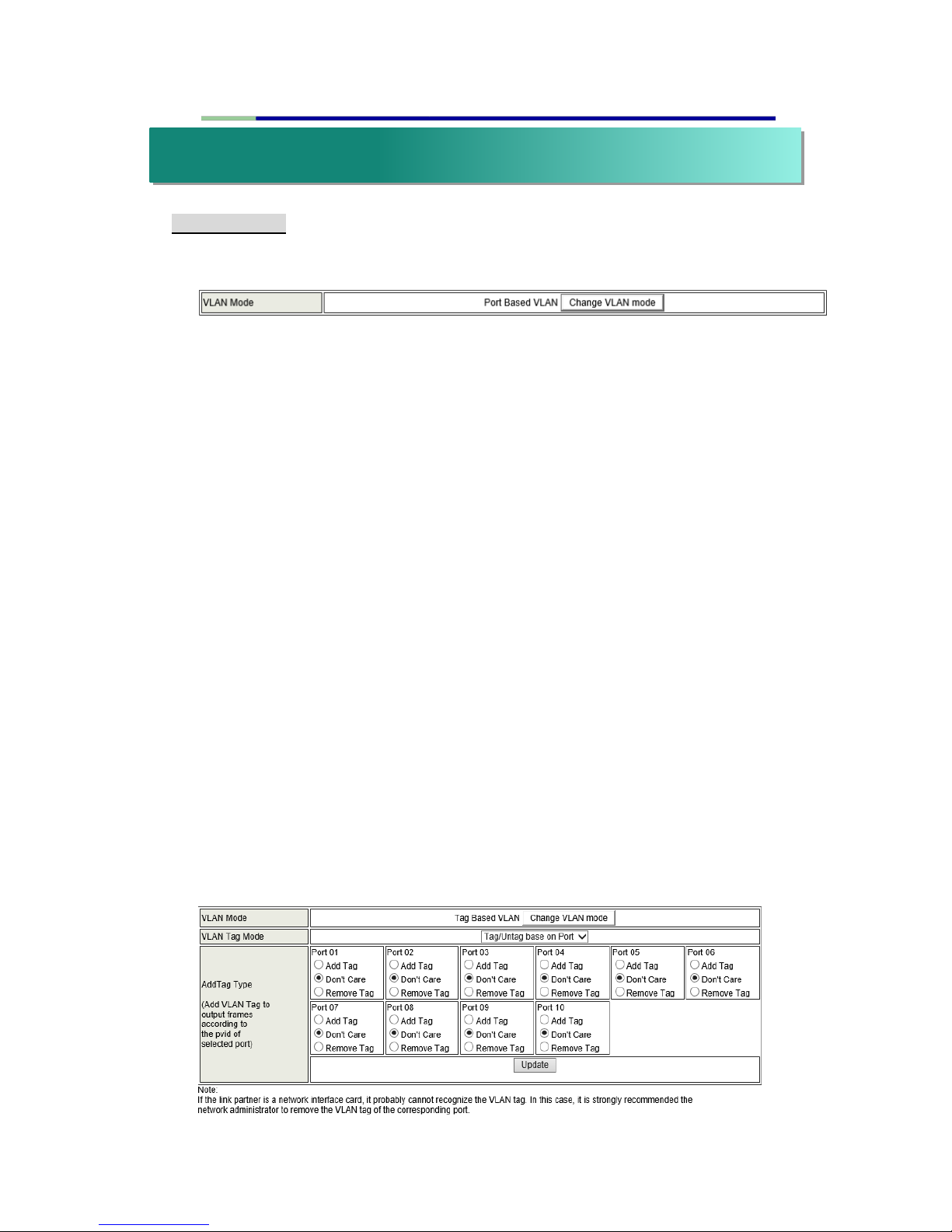
* VLAN mode
The smart switch supports two VLAN modes, tag based and port based. Only
one VLAN mode can be enabled at one time.
When the tag based VLAN is selected, the administrator can define the
handling method of a VLAN tag to the specified port, including “Add Tag”,
“don’t care” or “Remove Tag”. Add tag/Don’t Care/Remove tag definitions are
as follows.
“Add Tag” means the outgoing packet should contain a 802.1Q tag.
The 802.1Q tag will be inserted to the outgoing packet of the
selected port if the packet received at the source port does not
contain 802.1Q tag.
The original 802.1Q tag will be kept if the source port received a
packet with 802.1Q tag.
“Don’t care” means the outgoing packet of the selected port keep the original
packet format of the source port.
“Remove Tag” means the outgoing packet should not contain a 802.1Q tag.
The 802.1Q tag of the outgoing packet of the selected port will be
removed if the incoming packet received at the source packet
contains 802.1Q tag.
The packet format of the source port will be kept if the packet does
not contain the 802.1Q tag.
Note: In tag based VLAN mode, adding tag on the port which is used to
configure this switch is not allowed, because some NICs cannot recognize
802.1Q tag.
Example:
Port 1: The 802.1Q tag of every packet outgoing from this port will be
removed.
Port 4: The 802.1Q tag of every packet outgoing from this port should be
included.
Other ports: keep every outgoing packet intact.
vi. VLAN Setting
Page 19
19
* VLAN Member Setting
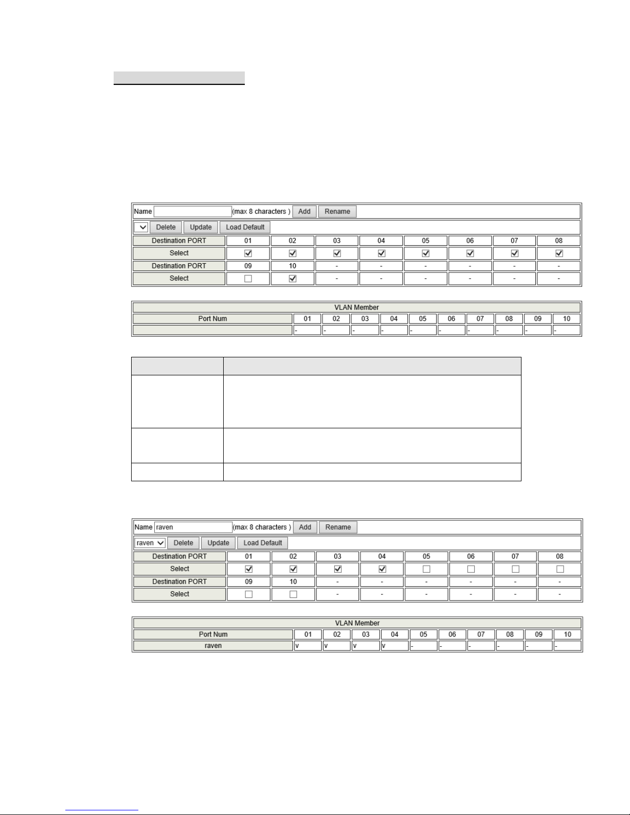
Port based VLAN
This web page is designed based on the VLAN member of each port. The
following examples illustrate how to configure VLAN in this mode.
The Table is configuring the port-based VLAN member of each port. When the
port received the packets allows only forwarded to the VLAN member of this port.
The function for each button shown on this page is displayed below.
Field
Description
Read
Select the port number which you want to read VLAN
member of this port.
Press “Read” button
Update
Select the VLAN member which you want to update.
Press “Update”
LoadDefault
Press this button to load default VLAN setting.
Example:
(a) Port 1 received packets can only forwarded to port 2, port 3 and port 4.
(b) Port 2 received packets, can only forwarded to port 1, port 3, port 4 and port 5.
(c) Port 3 received packets, can only forwarded to port 1 and port 2.
Page 20
20
Tag based VLAN on Port
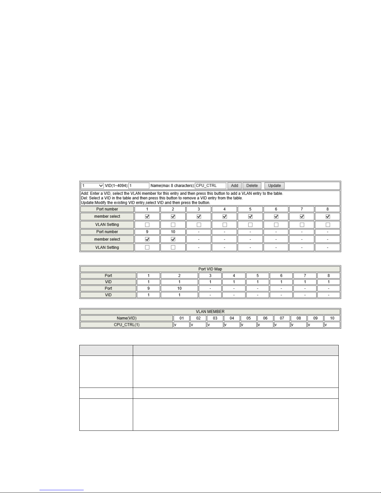
This web page allows the administrator configure to Tag-based VLAN
member of VID table of 32-entry and Port VID(PVID) source index of each
Port.
When a tagged packet is received, the Switch compares the tag in the
packet with the one defined in the VID table. The setting will be reflected at
VLAN MEMBER window.
When an un-tagged packet is received, the Switch searches for the PVID
source index. This PVID will be inserted to the received packet and then it
will be forwarded to the destination port according to the VLAN
membership corresponding to this PVID. The setting will be reflected at
Port VID Map window.
The function for each button shown on this page is expressed below.
Field
Description
Add a VLAN
Enter a VID, select the VLAN member and click the VID source
port and then enter a group name. Finally press “Add” button to
send this command. The VLAN will be added to the list.
Delete a VLAN
Select a VID and press “Delete” to remove a VLAN.
Modify a VLAN
Select a VID which you want to modify. After the web page
shows up, select the VLAN member and VID source port and
then press “Update”.
Page 21
21
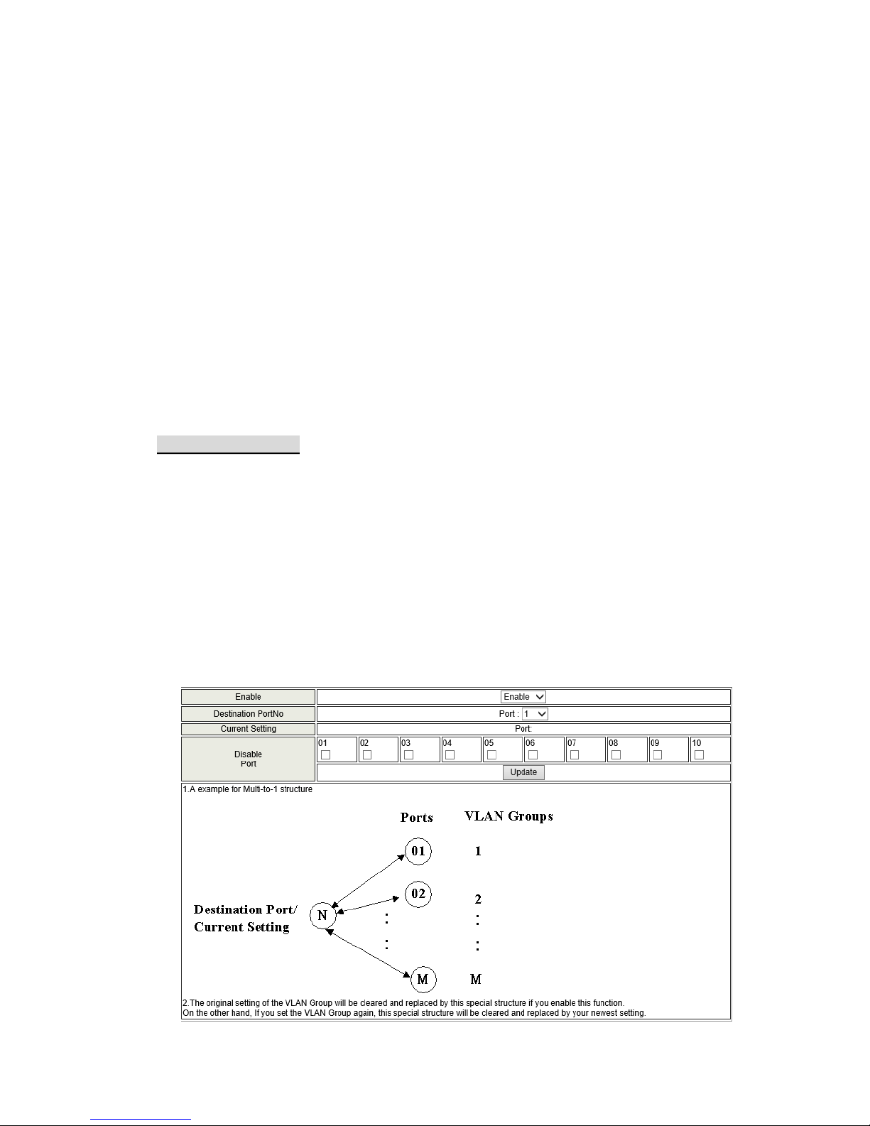
Add a VLAN Group
Step 1: Enter VID. The following example shows VID=45
Step 2: Select VLAN member
Step 3: Select the source port corresponds to this VID. You can select more
than one port for a VID.
Step 4: Press “Add” to add a VLAN group.
Modify a VLAN Group
Step 1: Select/De-select the VLAN ID
Step 2: Select/De-select VID source corresponding to this VID
Step 3: Press “Update”
* Multi-to-1 Setting
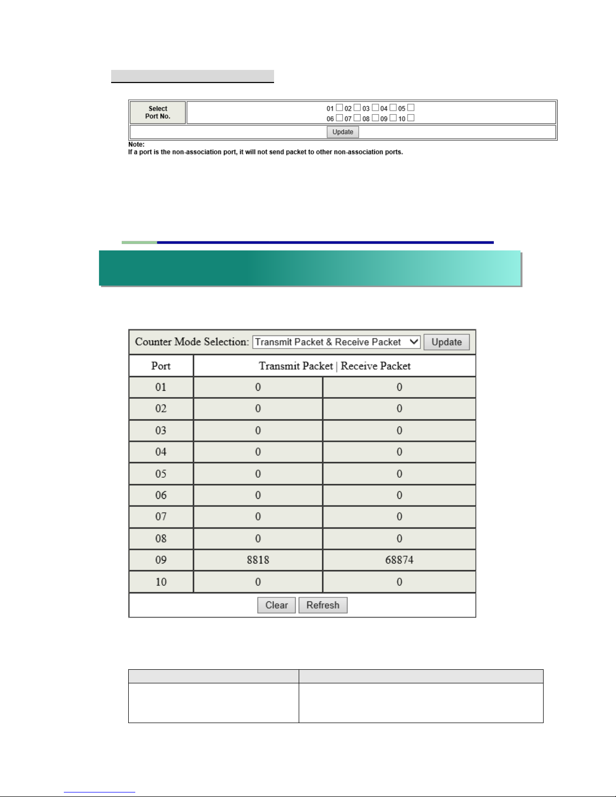
Multi-to-1 VLAN is used in CPE side of Ethernet-to-the-Home and is
exclusive to VLAN setting on ”VLAN member setting“. In the other words,
once multi-to-1 is set, the previous VLAN setting will be overridden.
The “disable port” means the port which will be excluded in this setting. All
ports excluded in this setting are treated as the same VLAN group.
In the following example, port 3, port 4, port 6, port 7, port 8 and port 9 are
excluded in this VLAN Furthermore these ports are treated as the member
of other VLAN. All ports which are not specified in this table only
communicate with port 1.
Page 22
22
* Non-Association Port Setting
Create port isolation. When marking 1~9 checkboxes with your mouse, the
inter-transmission between port 1~9 will not be permitted but to only
connect port 10 which is not marked with its checkbox.
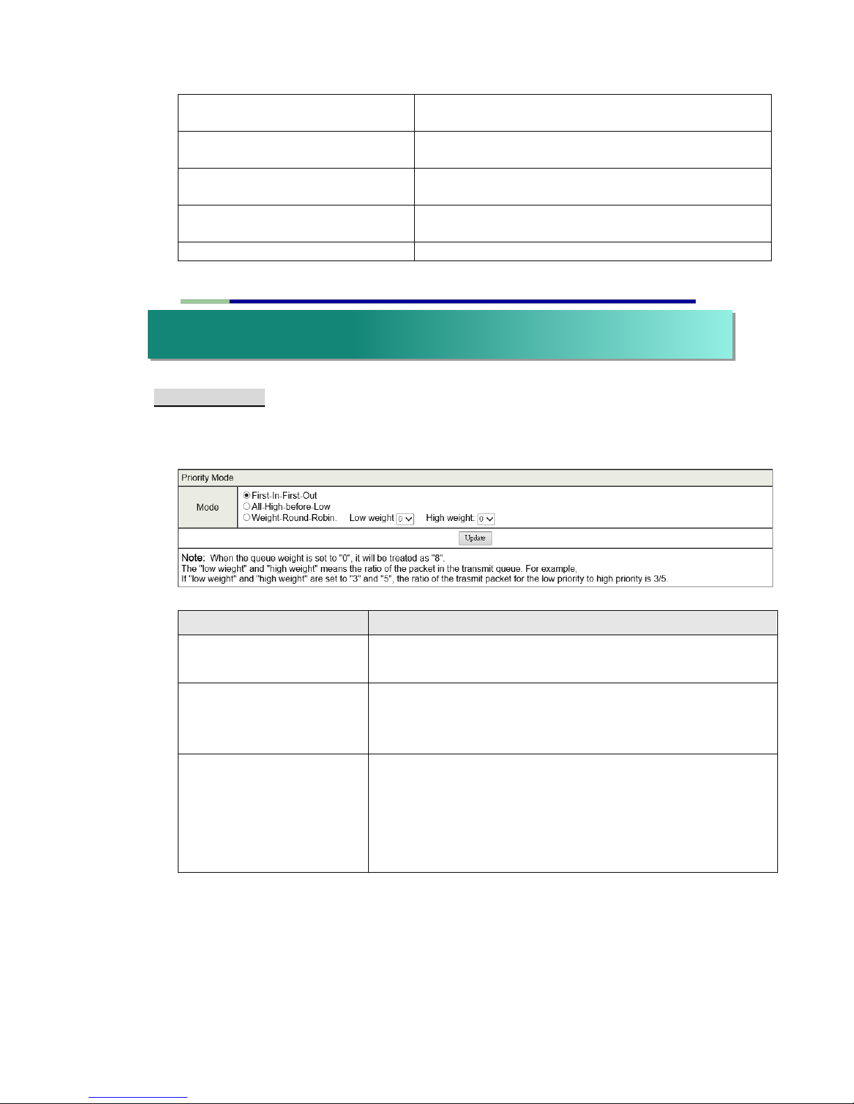
Counter Category
This page provides port counter for each port. There are 4 groups of
statistics in total. These 4 categories cannot work simultaneously. Once
you change the counter category, the counter will be cleared automatically.
Field
Description
Transmit Packet & Receive
Packet
This category shows both the received packet
count (excluding the incorrect packet) and the
transmitted packet count.
vii. Per Port Counter
Page 23
23
Collision Count & Transmit
Packet
This category shows the packets outgoing from
the switch and the count of collision.
Drop Packet & Receive Packet
This category shows the number of received valid
packet and the number of dropped packet.
CRC error Packet & Receive
Packet
This category shows the received correct packet
and received CRC error.
Refresh
Press “Refresh” button will aggregate the number
of the counter for all ports.
Clear
Press “Clear” button will clear all counters.
* Priority Mode
This page allows the administrator to set the scheduling mode for the TX
packets at each port.
Field
Description
First-In-First-Out
(FIFO)
All output packet are queued to one queue, first comes
first out.
All-High-before-Low
(Strict priority)
All packets will be assigned to either high priority queue
or low priority queue. The low priority packet will not be
forwarded until the high priority queue is empty.
Weight-Round-Robin
(WRR)
There are 2 priority queues for
Weighted-and-round-robin (WRR) mode. When this
mode is selected, the traffic will be forwarded according
to the number set in each queue. The queue ID has
nothing to do with the priority.
Example: If High, Low queue are set to 5, 3, then the traffic at the specific
port will go out in the following sequence. 5 packets stored in High queue, 3
packets stored in Low queue, 5 packets stored in High queue, 3 packets
stored in Low queue ……
viii. QoS setting
Page 24

24
* Class of Service Configuration
There are 4 types of CoS for this setting; ie, TCP/UDP port number, IP
TOS/DS, 802.1p priority tag and physical port. The administrator can select
more than one item for each port.
Please note that if more than one type of CoS is selected, the switch will
arrange the packet to the assigned queue according the following priority:
TCP/UDP port number the first, IP ToS/DS the second, 802.1p priority tag
the third and physical port the last. This means TCP/UDP port number will
override other CoS setting.
For 802.1p priority tag, the following table is used to map the 802.1p field to
the priory queue.
For IP TOS/DS priority, there are 7 kinds of TOS field can be assigned to
High or Low queues. i.e; 6’b101110, 6’b001010, 6’b010010, 6’b011010,
6’b100010, 6’b110000 and 6’b111000.
* Class of Service
The administrator can select the protocol that will be forwarded as the
specified mode. There are 3 administrator-defined UDP/TCP port groups
and many well-known TCP/UDP ports. The administrator-defined port
number may be a range or a specific number, depending on the mask.
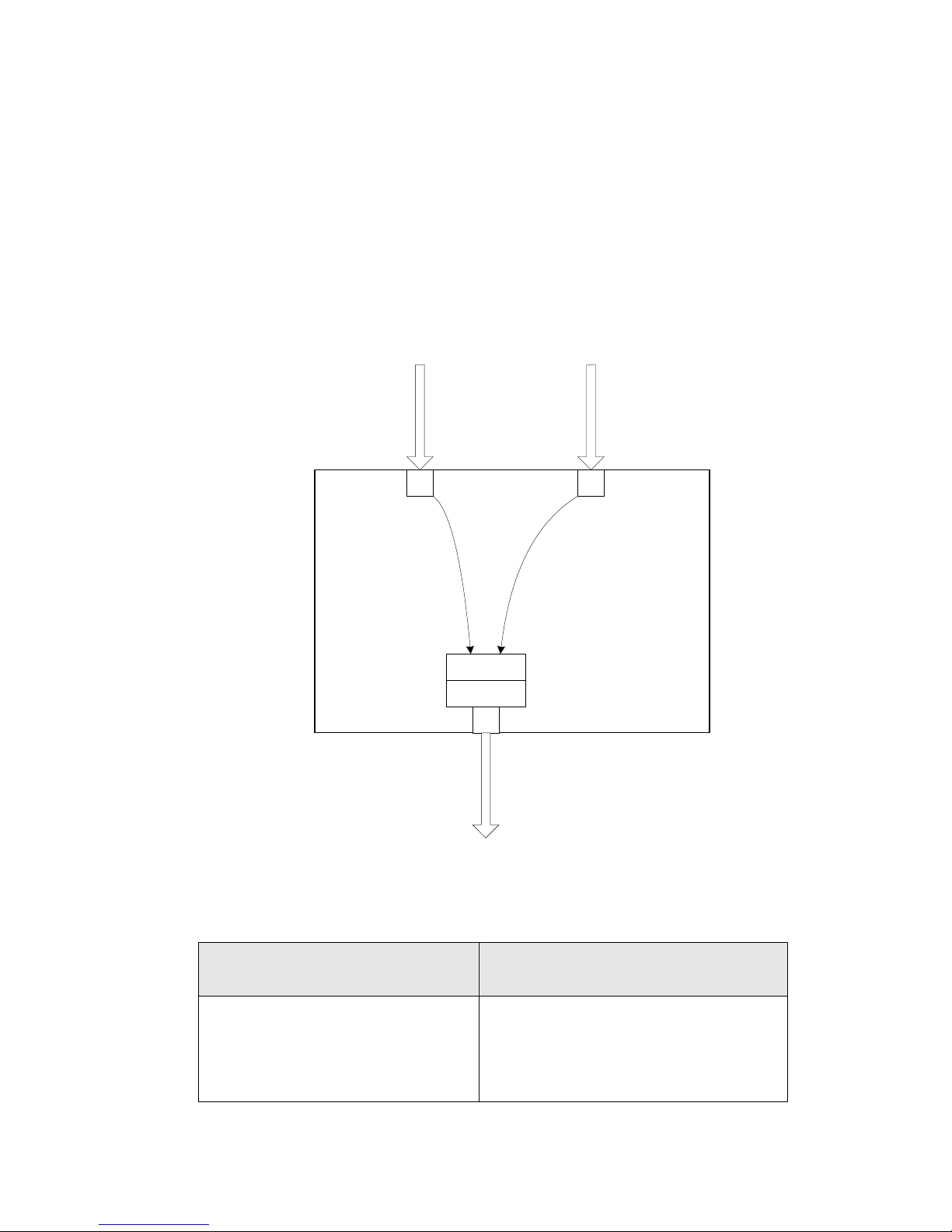
The operating theory for all 4 CoS types can be illustrated by the following
figure and table. TCP/UDP CoS, IP TOS/DS, 802.1p are global setting for
all ports and has no relation with the physical port.
Example:
(a) Priority Mode: WRR. High weight=4; Low weight=2
(b) TCP/UDP CoS: P2 FTP =>High queue; P5 SMTP => Low queue
Priory Field
Priority Queue
4,5,6,7
High
0,1,2,3
Low
Page 25
25
(c) TOS/DS setting: P5 TOS 6’b010010=High queue; P2 TOS
6’b100010=Low queue
(d) 802.1p: P2 802.1p = 6(High queue); P5 802.1p =1(Low queue)
(e) Physical port: P5=High queue; P2=Low queue
According to the rule described above, the CoS will be executed in the
following sequence.
TCP/UDP > TOS/DS > 802.1p > Physical
P 5
P 2
TOS/DS= 6'b010010
802.1p priority = 6
TOS/DS= 6'b100010
802.1p priority = 1
SMTP
Client 1
FTP
Client 2
P 3
High
Low
FTP Server,
SMTP Server
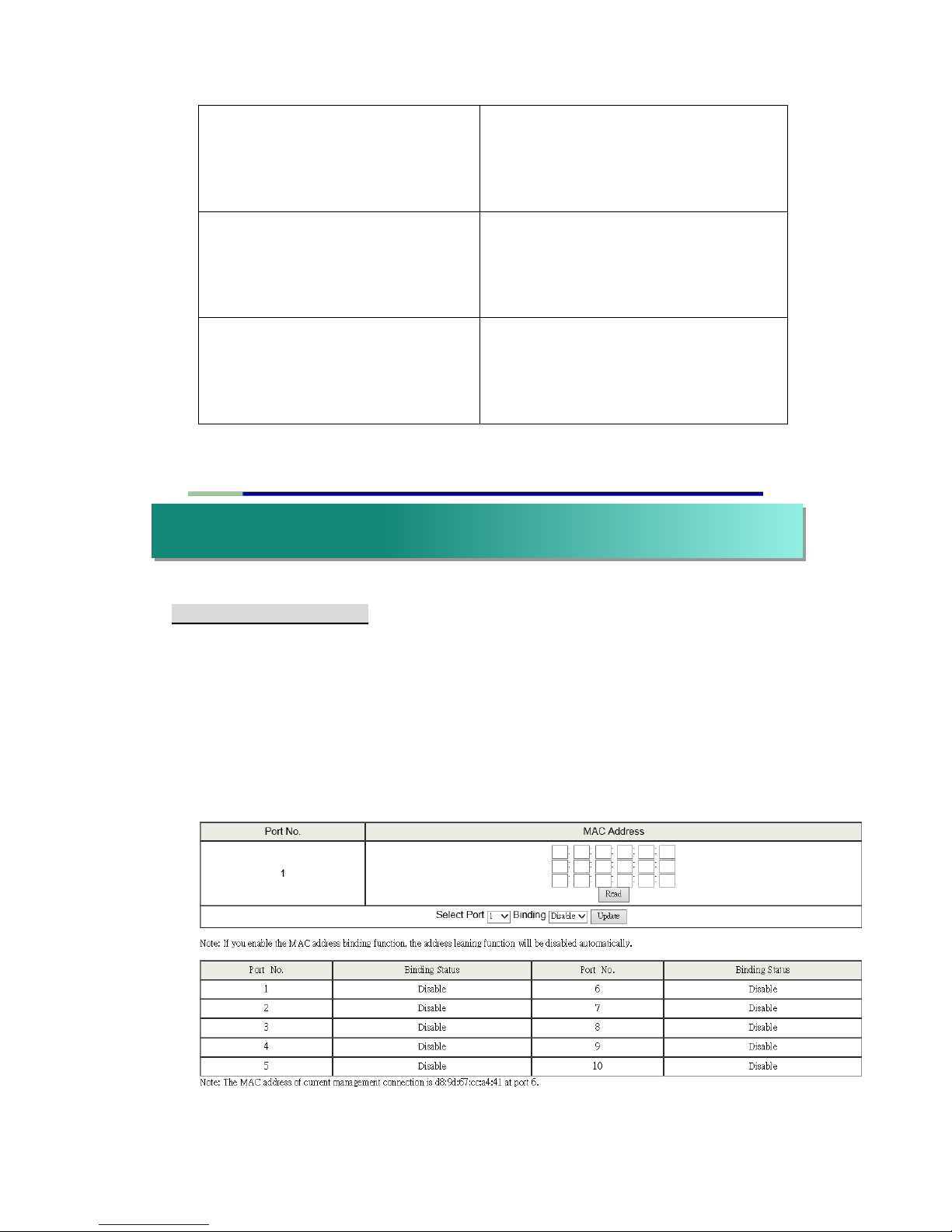
The actual CoS will behave like this table.
Switch Behavior Observed on
P3
Comment
4 packets coming from P2;
2 packets coming from P5;
4 packets coming from P2;
……….
If TCP/UDP CoS is enabled, the other
CoS setting will be ignored.
Page 26
26
2 packets coming from P2;
4 packets coming from P5;
2 packets coming from P2;
……….
If TCP/UDP CoS is disabled, the
switch will check TOS/DS CoS.
4 packet coming from P2;
2 packets coming from P5;
4 packets coming from P2;
……..
If TOS/DS CoS is disabled, the switch
will check the 802.1p field.
2 packet coming from P2;
4 packets coming from P5;
2 packet coming from P2;
……………..
If only physical port CoS is enabled,
the switch only check the physical
port CoS.
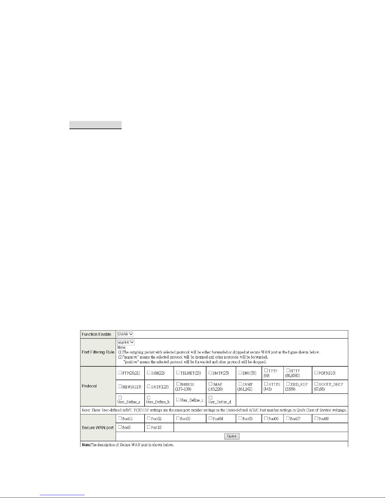
* MAC Address Binding
This function provides a method for the administrator to specify the relationship
between the physical port and the MAC address. Only the packet with specified
source MAC address can communicate with other port.
By specifying the MAC address to each port, the network administrator can
prevent the unauthorized administrator from accessing the switch. Each
port can bind up to 3 MAC addresses.
ix. Security
Page 27
27
To activate the port binding function, you should enter the correct MAC
address, select the port number, and set the port binding to “Enable” and
then press “Update”.
Note: Setting the multicast address to these fields is not allowed. A warning
message will show up if you do so.
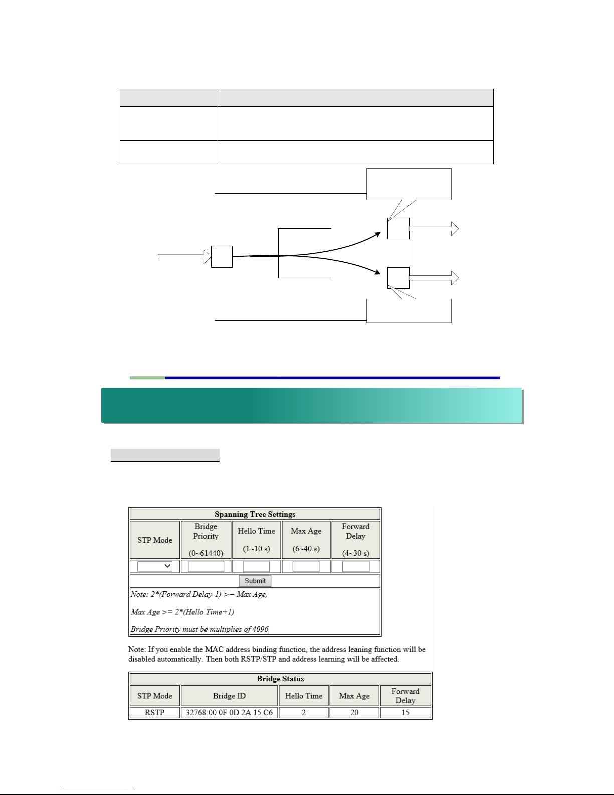
* TCP/UDP Filter
By selecting the TCP/UDP port, the network administrator can optionally
block some specific applications. There are two kinds of protocol filter
functions. The ”positive” function makes the switch forward the selected
protocol and drop other protocols.
The ”negative” function makes the switch drop the selected protocol and
forward other protocols. The protocol is checked at the secure WAN port.
And it should be set at the server side.
The figure shown below illustrates how this function is applied to the real
environment.
Example:
(a) Enable TCP/UDP Filter function.
(b) Select “positive” rule.
(c) Set port 5 as secure WAN port and select FTP and TELNET as the
filtering protocol.
(d) Place the server of the selected protocol at the secure WAN port.
Page 28
28
Result:
P 2
P 5
A Brief Description for Secure TCP/UDP Port
Check TCP/UDP
detination port at the
selected physical port.
Don't care the protocol
at these physical ports
Other
Ports
TELNET Client,
FTP Client,
HTTP Client
TELENT Server,
FTP Server,
HTTP Server
TELNET Server,
FTP Server,
HTTP Server
Switch
Engine
* STP Bridge Settings
The parameters concerning the configuration of RSTP/STP bridge are
described below.
Physical Port
The Behavior of Switch
Port 5
TELNET and FTP will be forwarded. Other protocol
will be discarded.
Other ports
All protocol will be forwarded as the normal packet.
x. Spanning Tree
Page 29
29
Field
Description
STP Mode
Disable: Disable RSTP/STP.
STP: Enable STP function.
RSTP: Enable RSTP function, including STP.
Bridge Priority
This field in conjunction with the MAC address forms
the Bridge ID. The lowest number of the Bridge ID in
a Spanning Tree domain will be selected as the root.
Enter a multiple of 4096 this field.
Hello Time, Max Age
and Forwarding Delay
These fields control how this device handles BPDU.
The relationship of these fields is listed below.
Note: 2*(Forward Delay-1) >= Max Age, Max Age >= 2*(Hello Time+1)
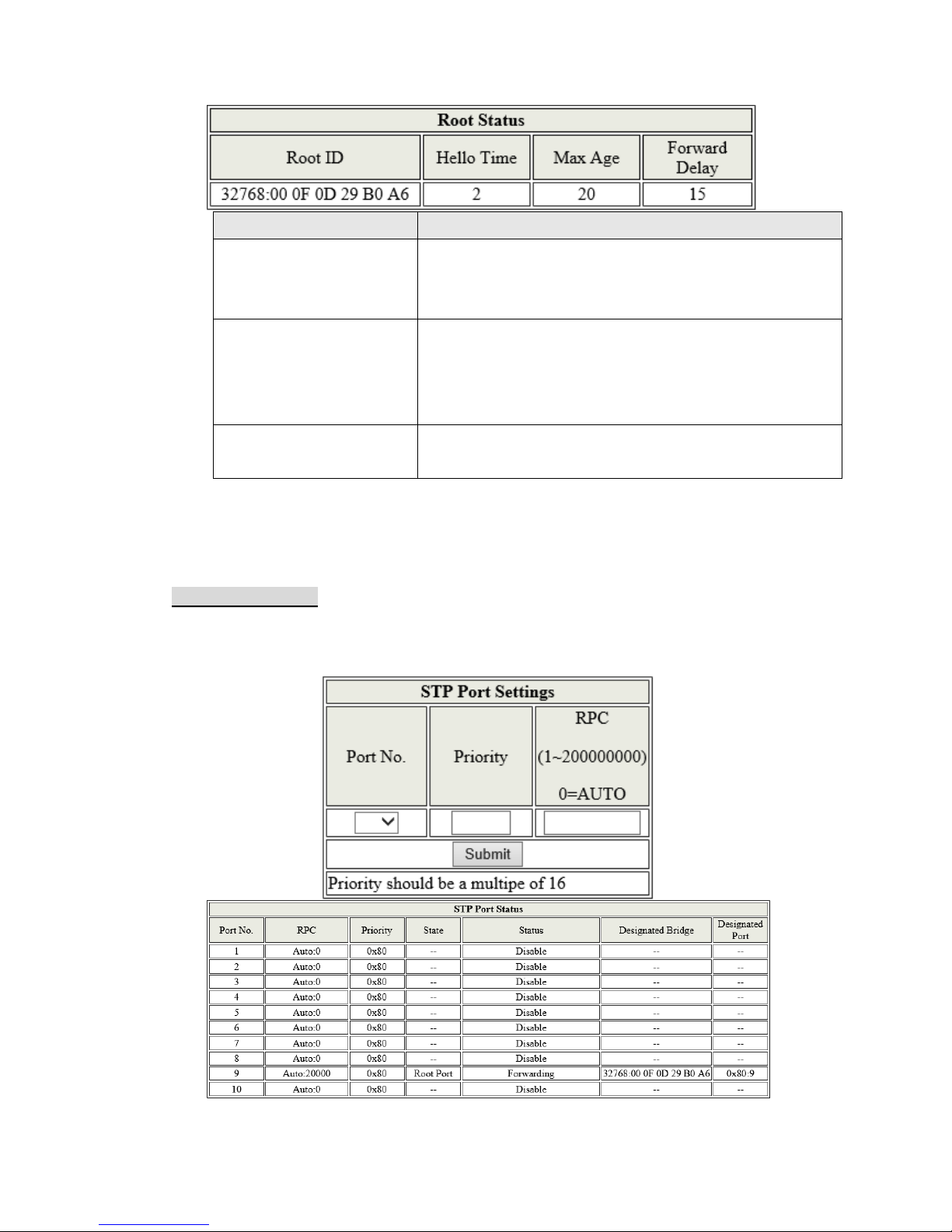
* STP Port Settings
This web page provides an interface for the administrator to set the
STP/RSTP port configuration.
Page 30
30
Field
Description
Port No.
To configure the parameters of RSTP/STP port, the
administrator should select a physical port number, assign a
priory number, enter the RPC and then press “Submit” button.
Priority (0~240)
Priority field defines the priority of the RSTP/STP port. The
lower the number is, the higher possibility it will become a root
port. There is a default value for each port.
RFC
(0~200000000)
RPC stands for “Root Path Cost”. The higher the cost is, the
lower possibility it become a root path. In the general case, the
physical port with the higher bandwidth will be assigned a lower
cost.
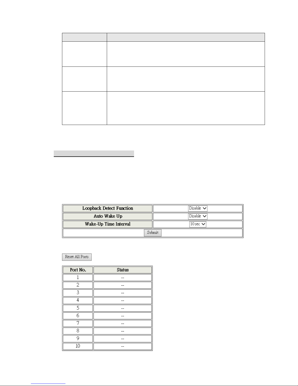
* Loopback Detection Settings
This web page provides loopback detection function. When loopback
detection function is enabled and a port received its own BPDU, the
detection agent drops the loopback BPDU and places the interface in
discarding mode. This loopback status can be released automatically, if
auto wake up function is enabled.
Page 31
31
Field
Description
Loopback Detect Function
Enable/Disable the loopback detect function.
Auto Wake Up
Enable/Disable auto wake up for loopback
detection of each ports.
Wake-Up Time Interval
Set auto wake up time value.
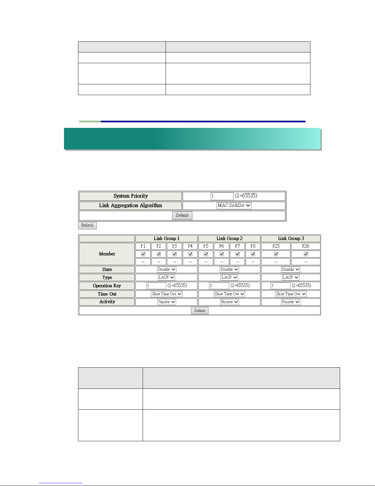
This page is used to set trunk group for load balance and cable link auto-backup.
There are 2 methods to set a trunk; i.e. Static and LACP.
The meaning of each field shown in the following table is explained as following.
The smart switch supports three trunk groups, which can set port 1 ~ port 8,
port25 and port 26, and trunk 1 consists of port 1 ~ port 4, trunk 2 consists of port
5 ~ port 8, trunk 3 consists of port 25, port 26. Trunk hash algorithm can be
selected according to 2 different methods.
Link Aggregation
Algorithm
Description
SA
Among the trunk member ports, the packet will be distributed
based on the source MAC address.
DA XOR SA
Among the trunk member ports, the packet will be distributed
based on the XOR calculation result of the source MAC
address and the destination MAC address.
xi. Trunking
Page 32
32
Field
Description
Member
There are three configurable trunk groups.
“--“ means the trunk has not been built on the corresponding
port. “A” means trunk has been built on the corresponding port.
State
Administrator can enable/disable the function of this trunk.
Type
Static: Static setting by manual.
LACP: Setting by ACP.
Operation Key
Assign an operation key for this device
Time out
Short Time Out: Re-configure LACP trunk every 1 second.
Long Time Out: Re-configure LACP trunk every 30 second.
Activity
You should set at least one side of each trunk to “Active” state. If
both sides of a trunk are all set to “Passive”, LACP trunk will never
be built up.
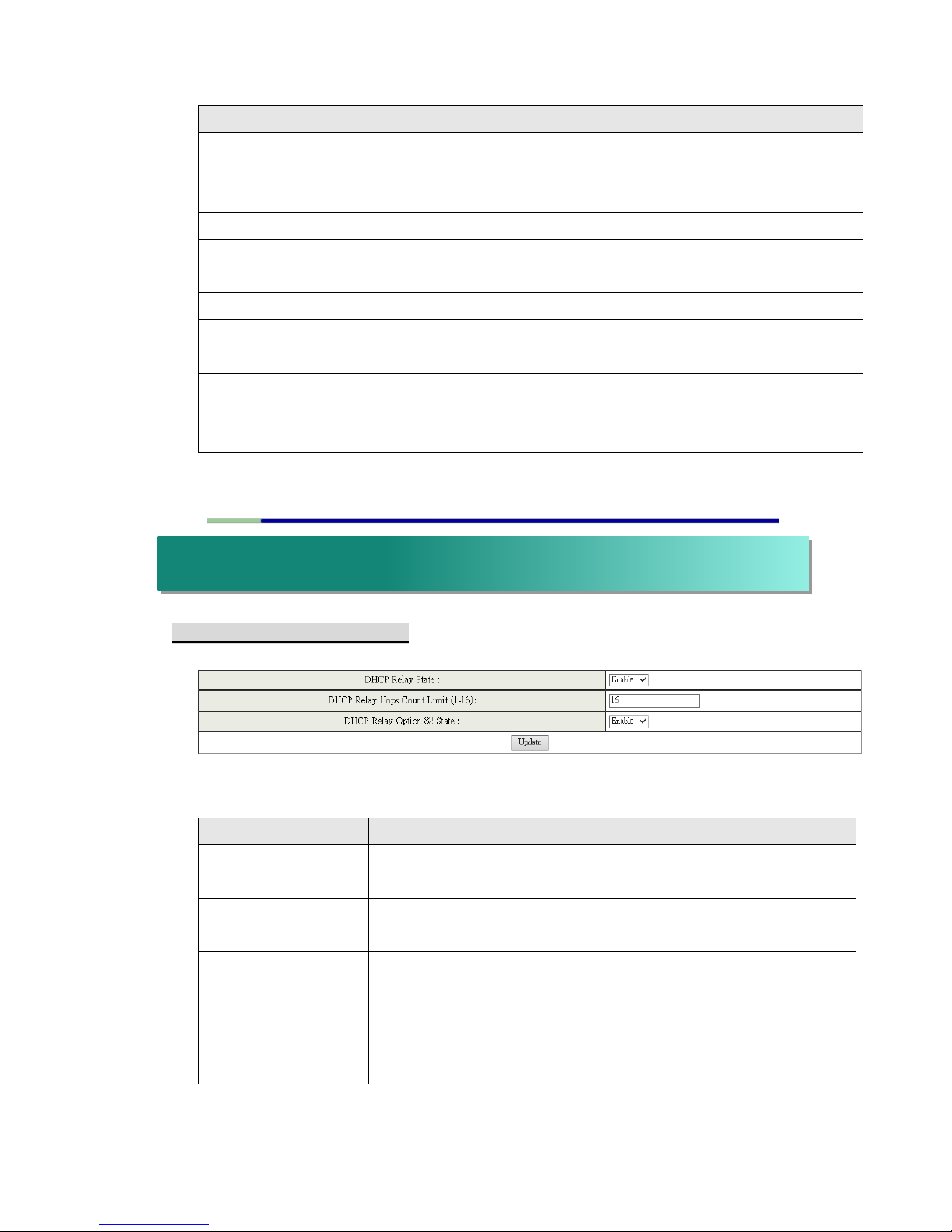
* Relay Agent Configuration
This web page allows the administrator to enable/disable DHCP Relay
Agent function. In addition, option 82 message is selectable by setting.
Field
Description
DHCP Relay State
Allow the administrator to enable/disable Relay Agent
function.
DHCP Relay Hops
Count Limit
Specify the maximum number of Relay Agent traveling from
DHCP agent to DHCP server.
DHCP Relay Option
82 State
The pre-condition for enabling/disabling this function is that
DHCP Relay State is set to “enable”. Once the Relay State is
set to “enable”, the administrator can enable/disable Option
82, depending on whether the Option 82 information is
required.
xii. DHCP Relay Agent
Page 33
33
* Server IP List
The IP address of DHCP server, which can be relayed by this Relay Agent,
should be specified on this web page.
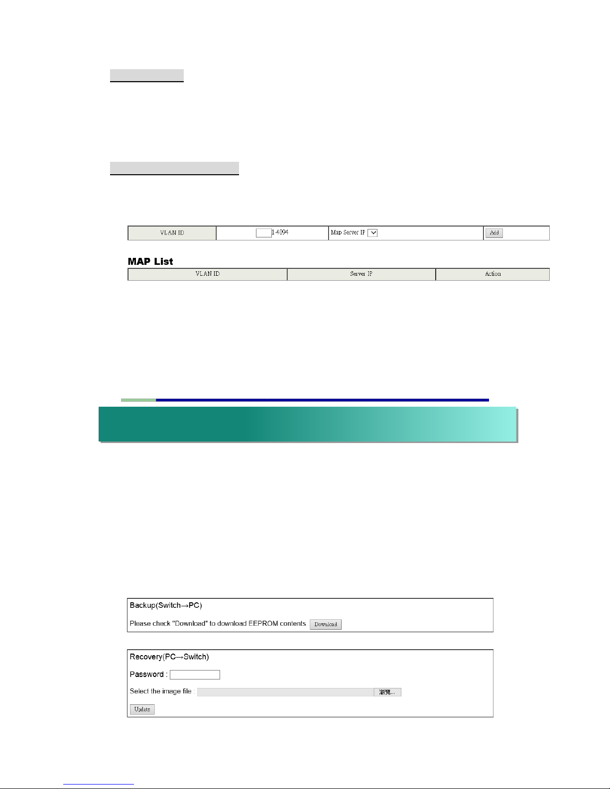
* VLAN to Server IP Map
This web page defines the relationship between the VLAN group and the
serve IP address.
Note: One server should belong to only one VLAN ID. If you set the same
server IP address to different VLAN ID, the warning message will show up,
as the figure shown below. You can set more than one server IP address in
a VLAN ID.
This function provides the administrator with a method to backup/recovery the
switch configuration. The administrator can save configuration file to a specified
file.
If the administrator wants to recover the original configuration, which is saved at
the specified path, just enter the password and then press the “Upload” button.
Finally the backup configuration of the switch will be recovered.
xiii. Backup/Recovery
Page 34
34
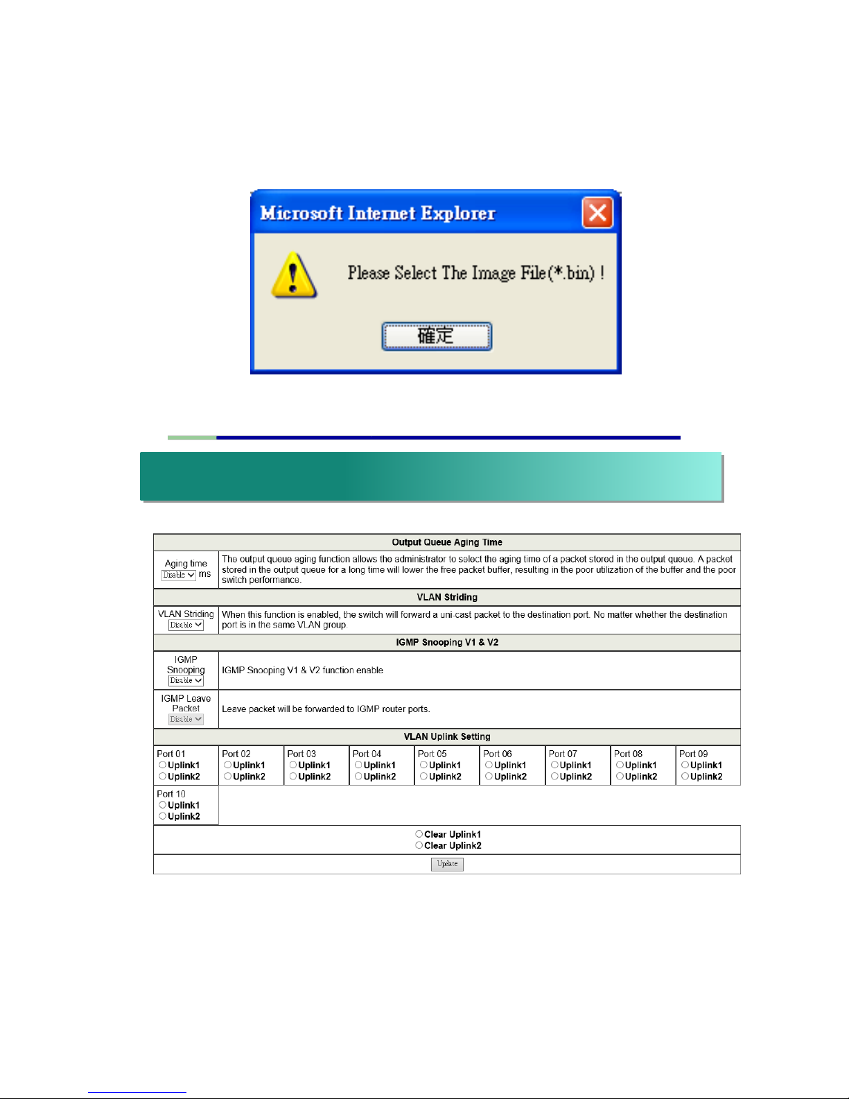
The switch will check whether or not the uploaded file is correct. If the
content of the uploaded file is incorrect, the switch will show a warning
message.
Miscellaneous setting is used to configure Output Queue Aging Time, VLAN
Striding, IGMP Snooping and VLAN Uplink.
xiv. Miscellaneous Settings
Page 35

35
* Output Queue Aging Time
This function is used to avoid the poor utilization of the switch. When a
packet is stored in a switch for a long time, the time slot defined by the
protocol will expire and this packet becomes useless.
To prevent these useless packets from wasting the bandwidth, this switch
provides an option to enable the queue aging function.
Once enabled, the switch will monitor the aging timer for each packet
before it is sent out. The packet which stays inside a queue for a long time
will be discarded.
* VLAN Striding
By selecting this function, the switch will forward uni-cast packets to the
destination port, no matter whether destination port is in the same VLAN.
* IGMP Snooping
When this function is enabled, the switch will execute IGMP snooping
version 1 and version 2 without the intervention of CPU. The IGMP report
packets are automatically handled by the switch.
When the user enable “Leave packet will be forwarded to IGMP router
ports” function. If members want to leave this multicast group, the IGMP
leave packet will be forwarded to the router ports.
* VLAN Uplink
In VLAN, the user can define the “Uplink port”. This is normally the port that
attached to the uplink router. This feature is similar to the “Router port”.
After that is set, any frame transferred to the other VLAN member is
forwarded only out the uplink port.
For example:
Step 1: set port 1, 2 and 3 are the same VLAN; set port 4, 5 and 6 are the
same VLAN.
Step 2: set port 1 is uplink port of Uplink 1, set port 4 is uplink port of Uplink
2, and press “Update” button.
Step 3: If port 2 want to send uni-case packet to port 5. The packet will be
transferred to the port 1.
Page 36
36
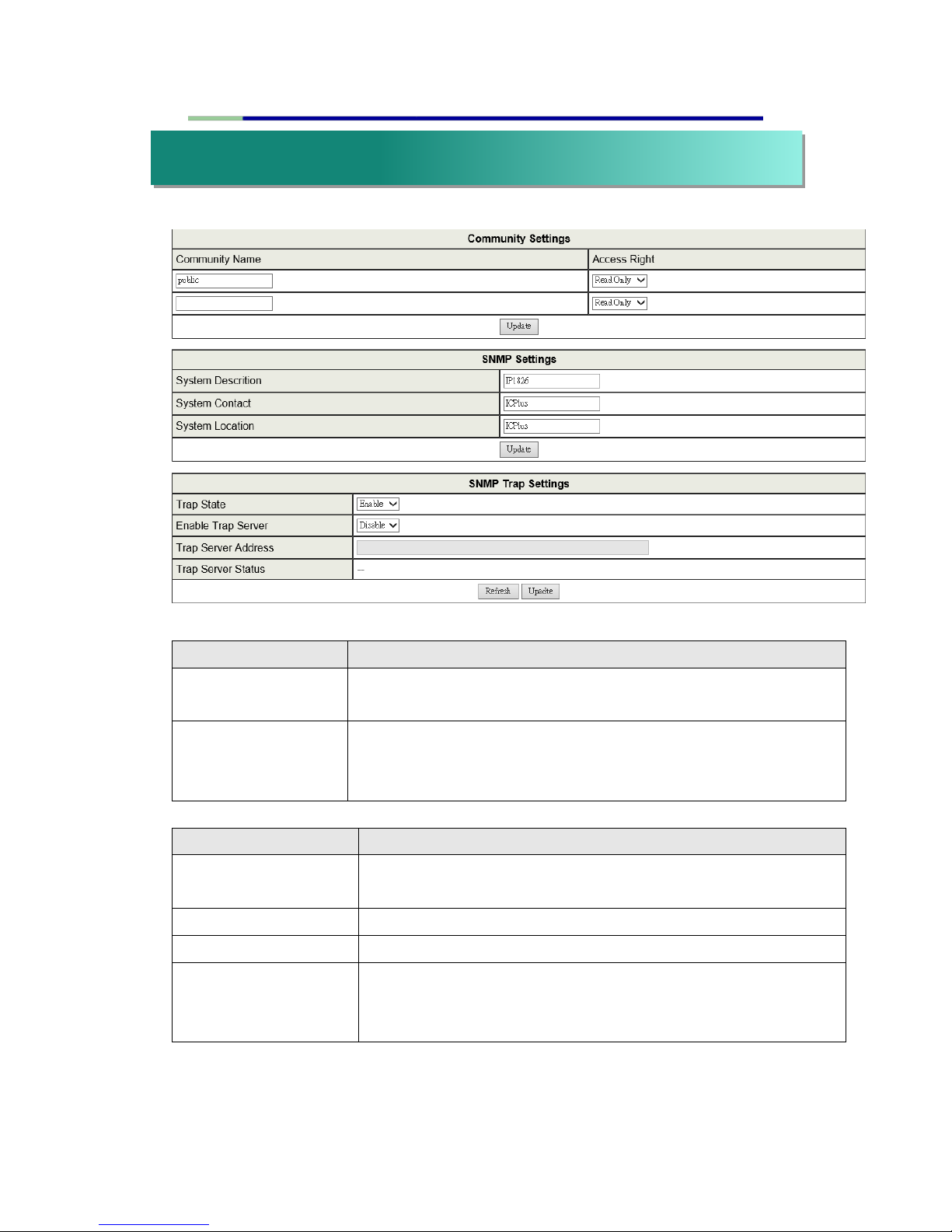
Field
Description
Community Name
This field allows the administrator to enter the community
name.
Access Right
This filed defines the access attribute. “Read only” means the
administrator can view this community only. “Read/Write”
means the administrator can view and modify this community.
Field
Description
System Description
The administrator can enter a device name for the
identification in the network.
System Contact
The contact person responsible for maintaining network.
System Location
The location of this device.
Trap State
Enable/Disable trapped event. The trapped event are:
Power up event.
Physical port status change event.
xv. SNMP Settings
Page 37
37
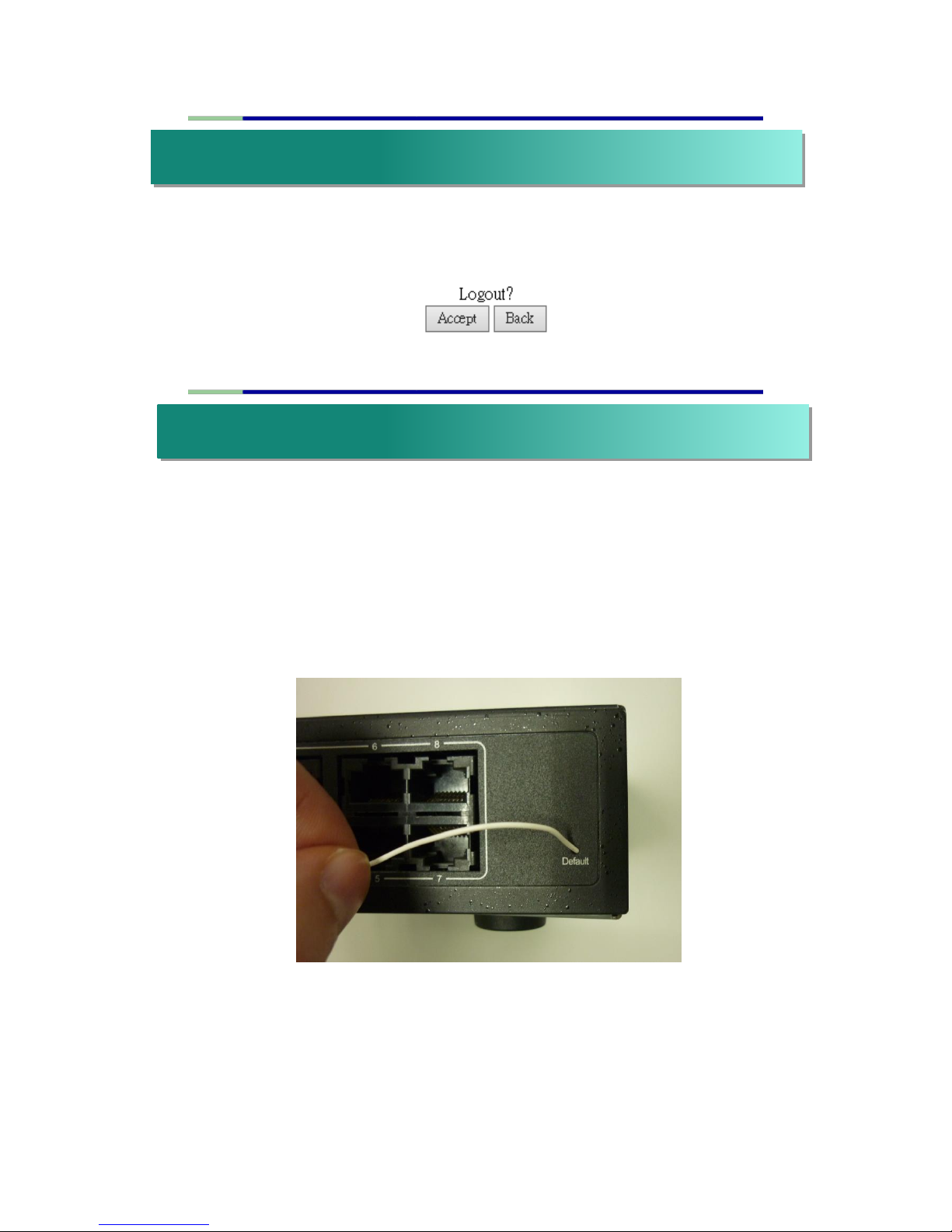
The page provides the administrator to logout web page. Press “Accept”
button to logout. Press “Back” button to browse the previous web page.
The purpose of this function is to provide a method for the network
administrator to restore all configurations to the default value.
(a) To activate this function, the administrator should follow the following
procedures.
(b) Take an electronic wire and plug it into the hole,
Press and hold the
button once it is reached. Do not release the button yet.
(c) After 30 seconds, remove the wire to release the default button from
inside.
After completing this procedure, all the factory default value will be restored.
This includes the IP address, the administrator name, the password and all
switch configurations.
xvi. Logout
xvii. Load Default Setting – Hardware Based
 Loading...