

Page 1
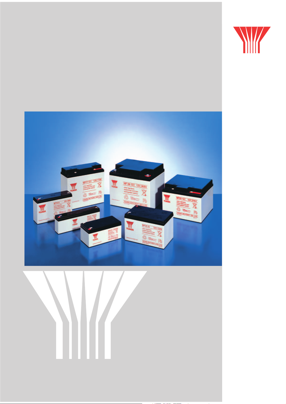
NP Baureihe – Series
Ventilgesteuerte Bleiakkumulatoren
Valve Regulated Lead-Acid Batteries
YUASA
YUASA BATTERY (EUROPE) GmbH
YUASA
Page 2
Ventilgesteuerte Bleisäureakkumulatoren
der Baureihe NP
YUASA
Valve Regulated Lead-Acid
Batteries NP
Yuasa als der in Europa marktbeherrschende Hersteller von wartungsfreien stationären
Industriebatterien hat die Baureihe NP, deren Produktion im letzten Jahrzehnt
bei über 40 Millionen Einheiten lag, technisch in betriebs- und zuverlässigkeitsbestimmenden
Eigenschaften permanent verbessert, so daß der Anwender ein absolut ausgereiftes
und kommerziell breit eingeführtes Produkt erwirbt, das in einer Vielzahl von Anwendungen
seine Zuverlässigkeit bewiesen hat.
Yuasa as leading manufacturer of valve regulated lead-acid batteries has been
improving all properties determining reliability and operational performance.
The effect is that the end-user acquires a fully mature and commercially accepted product,
which has proved its reliability in many various applications.
Allgemeine Produktmerkmale – General Features
• Lebensdauer: 3-5 Jahre nach Eurobat
Design life: 3-5 years according to Eurobat
• NP-Batterien können dauerhaft in Seitenlage betrieben werden
NP batteries can permanently be operated in any orientation excluding continuous use inverted.
• Schlag- und bruchfestes Kunststoffgehäuse aus ABS
Mechanically strong ABS - container
• FR-Gehäusematerial auf Wunsch schwer entflammbar gemäß UL 94 VO,
entsprechend EN 60707
Container material for FR batteries on special request is extremely flame-retardant according to
UL 94 VO, equivalent to EN 60707
• Fertigung der NP Batterien gemäß EN ISO 9001:2000 Qualitätsmanagementsystem und EN ISO
14001:2000 Umweltmanagementsystem
Manufacture of NP batteries according to EN ISO 9001:2000 Quality Management Systems
and EN ISO 14001:2000 Environment Management Systems
• Verlängerung der Gebrauchsdauer aufgrund einer speziellen Legierung der positiven Platte
Extension of service life by means of a special alloy
• VdS/UL Zulassungen
Certified by VdS and Underwriters Laboratories
• Temperaturbereiche: Aufladung: -15° C bis +50° C
Entladung: -15° C bis +60° C
Lagerung: -20° C bis +50° C
Temperature ranges: Charging: -15° C up to +50° C
Discharging:-15° C up to +60° C
Storage: -20° C up to +50° C
Besondere Produktmerkmale – Particular Features
• Ventilgesteuerte Konstruktion, nahezu 100%ige Sauerstoffrekombination bei jedem Aufladevorgang
Valve regulated design with nearly 100% gas recombination during float charging
• Elektrolyt in Glasfaservlies gebunden (AGM=Absorbing GlassMatt Technology)
AGM = Absorbing GlassMatt technology in which the electrolyte is fully absorbed
• Kein Auffüllen des Elektrolyts notwendig
No topping up of electrolyte necessary
• Korrosionsbeständige Hochleistungsgitterplatten mit Blei-Kalzium Legierung
High current drain grid being resistant to corrosion by virtue of a lead-calcium alloy
2
YUASA Battery (EUROPE) GmbH
Page 3
• Weiter Betriebstemperaturbereich bei entsprechender temperaturabhängiger Spannungskompensation
Wide range of operating temperatures with temperature compensated charging
• Sehr gute Ladeeffizienz
Very good charging efficiency
• Kein Gefahrgut gemäß IATA
Classified as “non-spillable“ and therefore exempt from IATA Dangerous Goods Regulations
• Konformität zu EN 61056
Conforming to EN 61056
• Hohe Lebensdauer bei geringer Selbstentladung, 3% pro Monat bei 20° C
Extended shelf life at low self-discharge level approximately 3% per month at 20° C
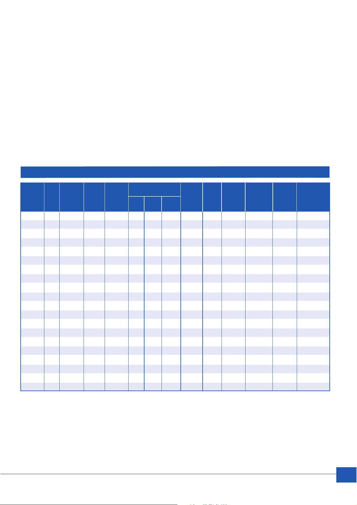
Allgemeine Spezifikation der Baureihe NP – NP Series General Specifications
FR Nenn- Kapazität Kapazität Gewicht Layout Pol-Typ Innenwider- Maximaler Kurzschlussstrom
BatterieType
Battery FR Nominal Capacity Capacity Länge/ Breite/ Höhe/ Weight Layout Terminal Internal Re- Maximum Short Circuit
Type Option Voltage [V] 20 h. 1,75V 10 h. 1,75V Length Width Height [kg] sistance mΩ Discharge Current Ik [A] acc.
NP1-6 x 6 1 0,9 51 42,5 54,5 0,25 5 A 179 7 36
NP1.2-6 6 1,2 1,1 97 25 54,5 0,31 1 A 147 8,4 44
NP3-6 6 3 2,8 134 34 64 0,57 1 A 59 21 109
NP4-6 6 4 3,7 70 47 105,5 0,85 5 A 44 28 145
NP7-6 x 6 7 6,5 151 34 97,5 1,35 1 A 25 49 254
NP10-6* x 6 10 9,3 151 50 97,5 1,93 1 A 18 70 363
NP12-6* 6 12 11,2 151 50 97,5 2,05 1 D 15 75 435
NP0.8-12 x 12 0,8 0,7 96 25 61,5 0,35 7 E 445 5,6 29
NP1.2-12* x 12 1,2 1,1 97 48 54,5 0,57 3 A 293 8,4 44
NP2-12 x 12 2 1,8 150 20 89 0,70 8 B 161 14 80
NP2.3-12* 12 2,3 2,1 178 34 64 0,94 1 A 155 16,1 83
NP3.2-12 x 12 3,2 3,0 134 67 64 1,17 3 A 111 22,4 116
NP4-12 x 12 4 3,7 90 70 106 1,70 1 A 89 28 145
NP7-12* x 12 7 6,5 151 65 97,5 2,65 4 A 51 49 254
NP7-12L x 12 7 6,5 151 65 97,5 2,65 4 D 51 49 254
NP12-12* x 12 12 11,2 151 98 97,5 4,09 4 D 30 84 435
NP17-12I* x 12 17 14,0 181 76 167 5,97 2 C 20 119 631
NP24-12I* x 12 24 22,3 166 175 125 8,92 2 C 15 168 871
NP38-12I* x 12 38 35,4 197 165 170 13,93 2 C 9 266 1.379
NP65-12I* x 12 65 60,5 350 166 174 22,82 2 C 5 455 2.395
Option spannung [V] 20 h. 1,75V 10 h. 1,75V [kg] stand mΩ Entladestrom Ik [A] gem
Abmessungen/
Dimensions [mm]
[A] IEC 896-2
Current [A] to IEC 896-2
* mit VdS-Zulassung
* with VdS-approval
FR = schwer entflammbarer Container
FR = flame retardant container
YUASA Battery (EUROPE) GmbH
3
Page 4
Anwendungsbereiche
Main Fields of Application
• Unterbrechungsfreie Stromversorgung (USV)
• Telekommunikation
• Feueralarm- und Sicherheitssysteme
• Medizinische Geräte
• Photovoltaische Anwendungen
• Steuer- und Regelungssysteme
• Elektronische Testgeräte
• Geophysikalische Geräte
• Marine Ausrüstungen – Bahn
• Uninterruptible Power Supply (UPS)
• Telecommunication
• Fire alarm and security systems
• Medical appliance
• Solar applications
• Electronic test equipment
• Electronic measuring devices
• Geophysical devices
• Marine equipment – Railway
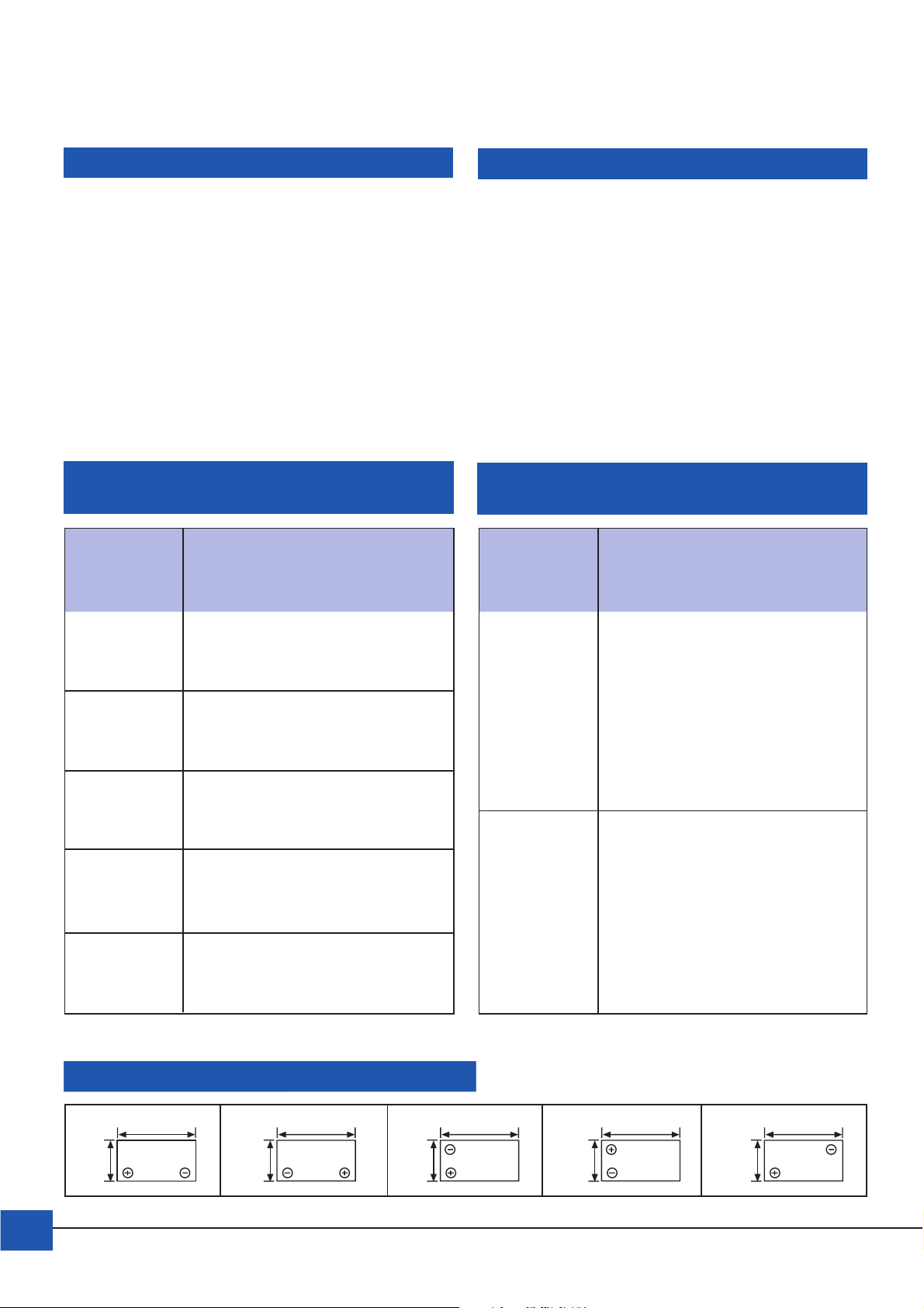
Empfohlene Entladeschlußspannung Top-Charging-Empfehlungen
Recommended Cut-off Voltage Top-Charging-Recommendation
Entladestrom Entladeschlußspannung Batteriealter Top-Charging
pro Zelle (V/Zelle) Lagerzeit Empfehlung
Discharge Cut-off Voltage/cell Battery Age Top-Charging
Current Storagetime Recommendation
<
0,10 CA 1,75 V/Zelle bis 6 Monate 4 – 6 Std. mit 0,1 C Konstantstrom
=
V/cell nach oder 15 bis 20 Stunden mit
Herstellung Konstantspannung 2,4V/Zelle
up to 6 months
0,17CA 1,70 V/Zelle
V/cell
0,26 CA 1,67 V/Zelle
V/cell
0,60 CA 1,60 V/Zelle Herstellung spannung 2,4 V/Zelle
V/cell
3 CA 1,50 V/Zelle
V/cell
Entladetiefe beeinträchtigt
die Lebensdauer
Depth of discharge
detrimental to service life
after date of
manufacture
bis 12 Monate 8 –10 Std. mit 0,1C Konstantstrom
nach oder 20 – 24 Stunden mit Konstant-
up to 12 months
after date of
manufacture
4 – 6 hours at 0,1 C constant current
or 15 – 20 hours at constant voltage
2,4V/cell
länger als 72 Std.
mit Konstantspannung 2,275 V/Zelle
more than 72 hours
at constant voltage 2,275 V/cell
8 – 10 hours at 0,1 C constant current
or 20 to 24 hours at constant voltage
2,4V/cell
48 – 144 Std. mit Konstantspannung
2,35 V/Zelle
48 – 144 hours
at constant voltage 2,35 V/cell
Position der Batteriepole – Terminal Location
12
n
M
n
M
4
3
n
YUASA Battery (EUROPE) GmbH
M
45
n
M
M
n
Page 5
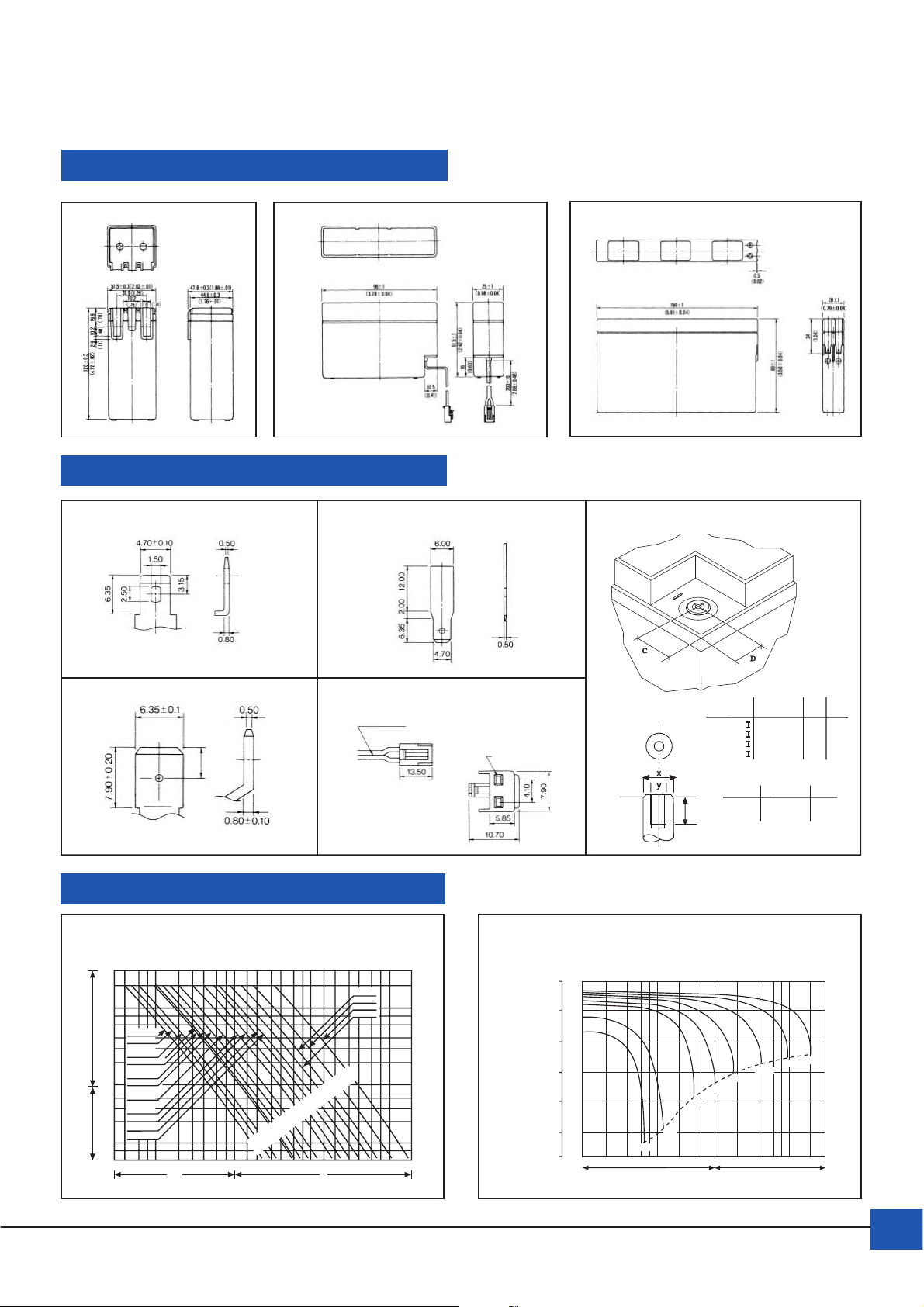
Abmessungen – Dimensions
6
Poltypen – Terminals
A
7
B
8
Polabstände – Terminal Design
C
DE
Kabel: AWG # 20 UL 1007
JST SVH-21T-P1.1
Spezifikationen – Specifications
hours
Stunden
minutes
Minuten
Entladekapazität
Capacity Selection Chart
20
10
8
6
NP0.8-12
4
NP1.2-6
NP1.2-6
3
NP1.2-12
NP1.9/2.1-12
2
NP2.8-6
NP2.8-12
NP3-6
60
NP4-6
NP4-12
40
NP6-12
30
NP7-12
20
NP10-6
NP12-6
10
8
6
60 80 200100 300 400 600 800 1000 2 3 4 6 8 10 20 30 40 60 80 100 200
30 40
mA A
0.8Ah
1.0Ah
1.2Ah
1.9Ah
2.1Ah
2.8Ah
3.0Ah
4.0Ah
6.0Ah
7.0Ah
10Ah
12Ah
17Ah
24Ah
38Ah
65Ah
NP24-12
NP38-12
NP65-12
NP17-12
20°C
Batterien/batteries
NP Entladecharakteristik bei 20°C
NP Discharge Characteristic Curves at 20°C
(V)
Für/for 12V
13.0
12.0
11.0
10.0
9.0
8.0
Gewinde/
NP
Thread
17 – 12
24 – 12
38 – 12
65 – 12
17 mm
z
20 mm
(V)
Für/for 6V
Batterien/batteries
6.5
6.0
5.5
5.0
0.6CA
4.5
4.0
3CA
124681020406024681020
1CA
2CA
Minuten/minutes
M5
M5
M5
M6
y z
x
M5 x 10
M6 x 16
0.2CA
0.4CA
Stunden/hours
0.1CA
Entladestrom/Discharge currentEntladestrom/Discharge current
C
12
12
22
23
4-5.5
20°C
0.05CA
Nm
2-3
D
43
40
19
30
YUASA Battery (EUROPE) GmbH
5
Page 6
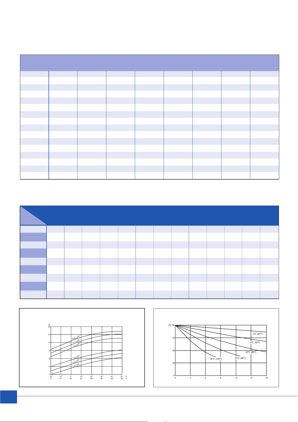
Entladestrom (Ampère) bei vorgegebener Entladerate
Discharge current (Ampères) at stipulated discharge rates
/hrs.
20 Std.
0,05C 0,1C 0,2C 0,4C 0,6C 1C 2C 3C
Kapazität
capacity
0,8 Ah
1
1,2 0,06 0,12 0,24 0,48 0,72 1,2 2,4 3,6
2 0,10 0,20 0,40 0,80 1,20 2 4 6
2,1 0,105 0,21 0,42 0,84 1,26 2,1 4,2 6,3
2,3 0,115 0,23 0,46 0,92 1,38 2,3 4,6 6,9
2,8 0,14 0,28 0,56 1,12 1,68 2,8 5,6 8,4
3 0,15 0,30 0,60 1,20 1,80 3 6 9
4 0,20 0,40 0,80 1,60 2,40 4 8 12
7 0,35 0,70 1,40 2,80 4,20 7 14 21
10 0,50 1,0 2,0 4,0 6,0 10 20 30
12 0,60 1,20 2,40 4,80 7,20 12 24 36
17 0,85 1,70 3,40 6,80 10 17 34 51
24 1,20 2,40 4,80 9,60 14 24 48 72
38 1,90 3,80 7,60 15 22 38 76 114
65 3,25 6,50 13 26 39 65 130 195
0,04 A 0,08 0,16 0,32 0,48 0,8 1,6 2,4
0,05 0,10 0,20 0,40 0,60 1 2 3
Konstant-Wattentnahme bei vorgegebener Entladeschlußspannung: Watt/Ah/Zelle bei 20° C
Power drain over time at stipulated cut-off voltages: Watt/Ah/Cell at 20° C
Entladezeit/
Discharge
V/Zelle
V/cell
1,6 5,421 3,884 3,074 2,554 2,211 1,943 1,767 1,621 1,490 1,201 0,721 0,524 0,346
1,63 5,303 3,864 3,016 2,533 2,191 1,938 1,747 1,611 1,471 1,198 0,716 0,521 0,343
1,65 5,268 3,806 2,984 2,513 2,178 1,914 1,743 1,602 1,458 1,194 0,713 0,518 0,341
1,67 5,173 3,740 2,952 2,503 2,159 1,895 1,728 1,589 1,445 1,186 0,708 0,515 0,339
1,69 5,056 3,712 2,922 2,477 2,128 1,881 1,705 1,580 1,432 1,174 0,704 0,513 0,337
1,7 4,945 3,632 2,907 2,467 2,116 1,872 1,702 1,567 1,422 1,171 0,700 0,511 0,335
1,75 4,692 3,551 2,822 2,372 2,048 1,819 1,648 1,517 1,373 1,151 0,682 0,496 0,326
1,8 4,493 3,389 2,559 2,272 1,964 1,754 1,579 1,444 1,318 1,086 0,658 0,478 0,314
1,85 4,130 3,163 2,526 2,144 1,857 1,655 1,482 1,350 1,240 1,023 0,622 0,459 0,300
Influence of temperature on battery capacity
5 M 10 M 15 M 20 M 25 M 30 M 35 M 40 M 45 M 60 M 2 Std. 3 Std. 5 Std.
time
Temperatureinfluß auf die Batteriekapazität
Selbstentladeverhalten bei verschiedenen Temperaturen
2 hrs. 3 hrs. 5 hrs.
NP Self Discharge Characteristics at various temperatures
available capacity %
percent of available capacity
Prozentsatz der verfügbaren Kapazität
Temperatur – temperature
6
YUASA Battery (EUROPE) GmbH
Verfügbare Kapazität %
Lagerzeit in Monaten – shelf life in months
Page 7
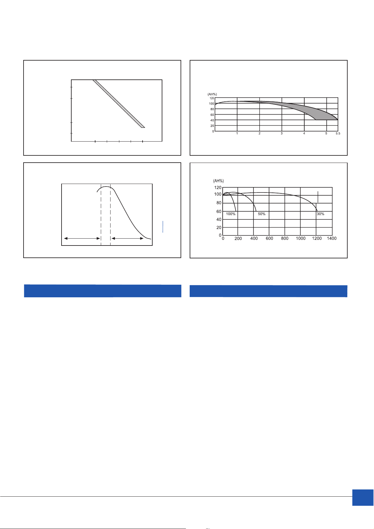
Temperatur/Gebrauchsdauercharakteristik der NP Batterien
Temperature/Life Characteristics of NP Batteries
Jahre – Years
100 %
75 %
33%
7%
Gebrauchsdauer (%)
Years of design life (%)
3%
20 30 40 50 60 °C
Temperatur – Temperature
Schwebeladespannung:
2,275 V/Zelle
bei 20°C Batterie Temperatur
Floating voltage:
2,275 V/cell
at 20°C battery temperature
Gebrauchsdauer im Schwebeladebetrieb (2,275 V/Zelle)
Service Life – Float Charge (2,275 V/cell)
bei/at 20°C
Percentage of capacity available
Prozentsatz der verfügbaren Kapazität
Lebensdauer (Jahre) – Life (years)
Gebrauchsdauer in Abhängigkeit
der Schwebeladespannungsvariabilität
100
Battery Life (%)
Batterie-Lebensdauer (%)
Schwebeladespannung (V/Zelle) – Float charge voltage (V/cells)
Float Charge/Battery Life
75
50
25
unterladen überladen
under charge
2,1 2,2 2,3 2,4 2,5
over charge
empfohlener Ladespannungsbereich 2,275V
recommended area of charging voltage
YUASA NP Serie, geprüfte Qualität
EN ISO Batterien aus unserer europäischen Produk-
9001:2000 tion werden nach Qualitätsstandard EN ISO
9001:2000 hergestellt
VdS- NP Akkumulatoren sind VdS geprüft
Zulassung
Anzahl der Zyklen im Verhältnis zur Entladetiefe
Cyclic Service Life in Relation to Depth of Discharge
bei/at 20°C
D.o.D. D.o.D. D.o.D.
Entladung/Discharge: 0,17 C(A)/1,7 vpc Anzahl der Zyklen
Percentage of capacity available
Ladung/Charge: 0,09 C (A) Number of cycles
Ladevolumen entnommene Kapazität/ DOD=Entladetiefe
Prozentsatz der verfügbaren Kapazität
Charging Volume of Discharge Capacity: 125% DOD=Depth of Discharge
YUASA NP Series Standardized Quality
EN ISO Batteries from our European factory are
9001:2000 manufactured in accordance
with EN ISO 9001:2000
VdS NP batteries are approved by VdS
Approval
IEC 61056/ Internationaler Standard für
IEC 60896-2 ventilgesteuerte Bleiakkumulatoren
DIN-Normen Wie DIN-43534; Akkumulatoren mit Gitter-
platten und festgelegtem Elektrolyt
DIN-Kurzzeichen: GiV
UL- Die Baureihe NP ist im UL-Sicherheits-
Anerkennung standard unter MH 12970 und MH
28018 registriert
IATA Yuasa NP Batterien sind kein Gefahrengut
gemäß IATA. Sie sind als auslaufsicher
klassifiziert.
YUASA Battery (EUROPE) GmbH
IEC 61056/ In accordance with International Standard
IEC 60896-2 for valve regulated lead-acid batteries
DIN Standards Like DIN-43534, accumulators with grid
plates and electrolyte absorbing glass-matt
UL-Approval Yuasa NP-series batteries are approved
and listed in UL Directory with file no.
MH 12970 and MH 28018.
IATA Yuasa NP series batteries are exempt
from IATA Dangerous Goods Regulations.
They are classified as non-spillable.
7
Page 8
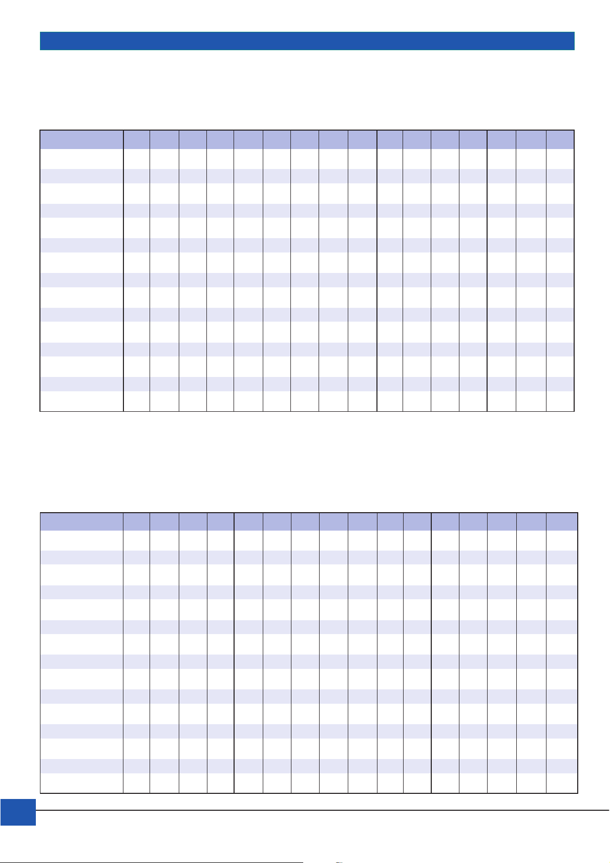
Konstant-Leistungs-/Strom-Entladedaten – Constant Power / Current Drain Discharge Data
NP Konstantleistungsentnahme (Watt/Zelle) bei 1,60 V/Zelle Entladeschlußspannung bei 20°C
NP Constant Power Discharge (Watt/cell) to 1.60 V/cell cut-off voltage at 20°C
Autonomie in Minuten
Autonomy in minutes
Typ – Type 51015202530354045123581020
NP 1-6 5,4 3,9 3,0 2,5 2,2 1,9 1,7 1,6 1,5 1,2 0,7 0,5 0,35 0,29 0,21 0,1
NP 1.2-6 / NP 1.2-12 6,5 4,7 3,6 3,0 2,6 2,3 2,1 1,9 1,8 1,4 0,9 0,6 0,4 0,3 0,25 0,12
NP 3-6 16,3 11,7 9,22 7,66 6,63 5,83 5,3 4,86 4,47 3,5 2,15 1,57 1,04 0,87 0,63 0,3
NP 4-6 / NP 4-12 21,7 15,5 12,3 10,2 8,8 7,8 7,1 6,5 5,9 4,8 2,9 2,1 1,4 0,96 0,75 0,4
NP 7-6 / NP7-12 37,9 27,2 21,5 17,9 15,5 13,6 12,4 11,3 10,4 8,4 5,0 3,7 2,4 1,56 1,27 0,71
NP 10-6 54,2 38,9 30,7 25,5 22,1 19,4 17,7 16,2 14,9 12 7,2 5,2 3,4 2,5 1,85 1,2
NP 12-6 / NP 12-12 65,1 46,6 36,9 30,6 26,5 23,3 21,5 19,4 17,8 14,4 8,6 6,3 4,1 2,7 2,25 1,34
NP 0.8-12 4,3 3,1 2,4 2 1,8 1,5 1,4 1,3 1,2 1,0 0,6 0,4 0,3 0,18 0,15 08
NP 2-12 10,8 7,7 6,1 5,1 4,5 3,9 3,5 3,3 2,9 2,4 1,5 1,2 0,63 0,48 0,37 0,2
NP 2.3-12 12,5 9,0 7,0 5,8 5,3 4,5 3,9 3,7 3,4 2,7 1,6 1,3 0,7 0,5 0,4 0,2
NP 3.2-12 17,4 12,4 9,8 8,1 7,0 6,3 5,7 5,2 4,8 3,8 2,3 1,7 1,1 0,78 0,58 0,33
NP 17-12I 92,1 66,1 52,2 43,4 37,6 33,0 30,0 27,5 25,4 20,4 12,2 8,8 5,9 4,1 3,1 1,74
NP 24-12I 130 93,2 73,8 61,3 53,1 46,6 42,4 38,9 35,8 28,8 17,3 12,6 8,3 5,76 4,53 2,5
NP 38-12I 206 148 117 97,1 84,1 73,8 67,1 61,6 56,6 45,6 27,4 19,9 13,1 9,22 7,9 3,84
NP 65-12I 352 253 200 166 144 126 115 105 96,9 78,1 46,9 34,1 22,5 15,7 12,0 6,5
Autonomie in Stunden
Autonomy in hours
NP Konstantleistungsentnahme (Watt/Zelle) bei 1,65 V/Zelle Entladeschlußspannung bei 20°C
NP Constant Power-Discharge (Watt/cell) to 1.65 V/cell cut-off voltage at 20°C
Autonomie in Minuten
Autonomy in minutes
Typ – Type 51015202530354045123581020
NP 1-6 5,3 3,8 3,0 2,5 2,2 1,9 1,7 1,6 1,5 1,2 0,7 0,5 0,35 0,27 0,2 0,1
NP 1.2-6 / NP 1.2-12 6,3 4,6 3,6 3,0 2,6 2,2 2,0 1,9 1,7 1,4 0,9 0,6 0,4 0,28 0,24 0,12
NP 3-6 15,8 11,4 8,95 7,54 6,53 5,74 5,23 4,81 4,37 3,58 2,14 1,55 1,02 0,81 0,6 0,3
NP 4-6 / NP 4-12 21,0 15,2 12,0 10,1 8,7 7,7 7,0 6,4 5,8 4,8 2,9 2,1 1,4 0,93 0,74 0,4
NP 7-6 / NP 7-12 36,9 26,6 20,9 17,6 15,2 13,4 12,2 11,2 10,2 8,3 5,0 3,7 2,4 1,55 1,27 0,7
NP 10-6 52,7 38,1 29,8 25,2 21,8 19,1 17,4 16 14,6 11,9 7,1 5,2 3,4 2,3 1,83 11
NP 12-6 / NP 12-12 63,2 45,6 35,8 30,0 26,0 23,0 20,9 19,2 17,5 14,3 8,5 6,2 4,1 2,7 2,21 1,26
NP 0.8-12 4,2 3,0 2,4 2,0 1,8 1,5 1,4 1,3 1,2 1,0 0,6 0,4 0,3 0,18 0,15 0,08
NP 2-12 10,5 7,5 6,0 5,0 4,5 3,9 3,5 3,2 2,9 2,4 1,5 1,2 0,63 0,46 0,37 0,2
NP 2.3-12 12,0 8,8 6,9 5,8 5,3 4,5 3,9 3,6 3,4 2,7 1,6 1,3 0,72 0,5 0,4 0,25
NP 3.2-12 16,9 12,1 9,5 8,0 6,9 6,2 5,6 5,1 4,7 3,8 2,3 1,7 1,1 0,74 0,58 0,33
NP 17-12I 89,6 64,6 50,7 42,7 36,8 32,5 29,5 27,1 24,8 20,2 12,1 8,8 5,8 4,9 3,1 1,71
NP 24-12I 126 91,2 71,5 60,2 52,0 45,8 41,7 38,3 35,1 28,5 17,1 12,5 8,2 5,6 4,4 2,4
NP 38-12I 200 144 113 99,6 82,5 72,7 66,2 60,7 55,5 45,2 27,1 19,7 13,0 8,9 7,0 3,8
NP 65-12I 343 247 194 163 141 125 114 104 94,8 77,3 46,3 33,7 22,2 15,0 11,9 6,5
Autonomie in Stunden
Autonomy in hours
8
YUASA Battery (EUROPE) GmbH
Page 9

NP Konstantleistungsentnahme (Watt/Zelle) bei 1,70 V/Zelle Entladeschlußspannung bei 20°C
NP Constant Power-Discharge (Watt/cell) to 1.70 V/cell cut-off voltage at 20°C
Autonomie in Minuten
Autonomy in minutes
Typ – Type 5 1015202530354045 1 2 3 5 8 1020
NP 1-6 4,9 3,69 2,9 2,5 2,1 1,9 1,7 1,6 1,4 1,2 0,7 0,5 0,3 0,22 0,18 0,1
NP 1.2-6 / NP 1.2-12 5,9 4,4 3,5 3,0 2,5 2,2 2,0 1,9 1,7 1,4 0,8 0,6 0,4 0,26 0,22 0,12
NP 3-6 14,8 10,9 8,72 7,4 6,35 5,62 5,11 4,7 4,27 3,51 2,1 1,53 1,0 0,66 0,54 0,3
NP 4-6 / NP 4-12 19,8 14,5 11,6 9,9 8,5 7,5 6,8 6,3 5,7 4,7 2,8 2,0 1,3 0,88 0,72 0,4
NP 7-6 / NP 7-12 34,6 25,4 20,3 17,3 14,8 13,1 11,9 11,0 9,9 8,2 4,9 3,6 2,3 1,54 1,27 0,7
NP 10-6 49,5 36,3 29,1 24,7 21,2 18,7 17,0 15,7 14,2 11,7 7,0 5,1 3,3 2,2 1,8 1,0
NP 12-6 / NP 12-12 59,3 43,6 34,9 29,6 25,4 22,5 20,4 18,8 17,1 14,1 8,4 6,1 4,1 2,64 2,18 1,18
NP 0.8-12 4,0 2,9 2,3 2,0 1,7 1,5 1,4 1,3 1,1 0,9 0,6 0,4 0,3 0,18 0,15 0,08
NP 2-12 10,0 7,63 5,8 4,9 4,5 3, 8 3,4 3,1 2,8 2,3 1,4 1,2 0,63 0,44 0,37 0,2
NP 2.3-12 11,4 8,3 6,7 5,7 5,3 4,38 3,8 3,5 3,29 2,6 1,5 1,3 0,7 0,5 0,4 0,23
NP 3.2-12 15,9 11,6 9,4 7,9 6,8 6,0 5,4 5,0 4,6 3,7 2,2 1,6 1,0 0,74 0,58 0,32
NP 17-12I 84,1 61,8 49,4 44,2 35,9 31,8 28,9 26,6 24,1 19,9 11,9 8,7 5,7 3,7 3,1 1,66
NP 24-12I 119 87,2 69,9 59,2 50,8 44,9 40,8 37,6 34,1 28,1 16,8 12,3 8,0 5,28 4,32 2,35
NP 38-12I 188 138 111 93,7 80,5 71,2 64,8 59,5 54,0 44,5 26,2 19,4 12,7 8,36 6,84 3,72
NP 65-12I 321 236 189 160 138 122 111 102 92,4 76,1 45,5 33,2 21,8 14,3 11,7 6,3
Autonomie in Stunden
Autonomy in hours
NP Konstantleistungsentnahme (Watt/Zelle) bei 1,75 V/Zelle Entladeschlußspannung bei 20°C
NP Constant Power-Discharge (Watt/cell) to 1.75 V/cell cut-off voltage at 20°C
Autonomie in Minuten
Autonomy in minutes
Typ – Type 5 1015202530354045 1 2 3 5 8 1020
NP 1-6 4,8 3,6 2,8 2,4 2,0 1,8 1,6 1,5 1,4 1,2 0,7 0,5 0,3 0,22 0,18 0,1
NP 1.2-6 / NP 1.2-12 5,6 4,3 3,4 2,8 2,5 2,2 2,0 1,8 1,6 1,4 0,8 0,6 0,4 0,26 0,22 0,12
NP 3-6 14,1 10,7 8,47 7,12 6,14 5,46 4,94 4,55 4,12 3,45 2,05 1,49 0,98 0,66 0,54 0,3
NP 4-6 / NP 4-12 18,8 14,2 11,3 9,5 8,2 7,3 6,6 6,1 5,5 4,6 2,7 2,0 1,3 0,87 0,71 0,41
NP 7-6 / NP 7-12 32,8 24,8 19,8 16,6 14,3 12,7 11,5 10,6 9,6 8,1 4,8 3,5 2,3 1,5 1,27 0,7
NP 10-6 46,9 35,5 28,2 23,7 20,5 18,2 16,5 15,2 13,7 11,5 6,8 5,0 3,3 2,2 1,8 1,0
NP 12-6 / NP12-12 56,3 42,6 33,9 28,5 24,6 21,8 19,8 18,2 16,5 13,8 8,2 6,0 3,9 2,6 2,18 1,22
NP 0.8-12 3,8 2,8 2,3 1,9 1,6 1,5 1,3 1,2 1,1 0,9 0,5 0,4 0,3 0,17 0,15 0,08
NP 2-12 9,3 7,1 5,7 4,7 4,1 3,7 3,3 3,1 2,7 2,3 1,4 0,9 0,63 0,43 0,36 0,2
NP 2.3-12 10,7 8,1 6,6 5,5 4,7 4,3 3,7 3,5 3,2 2,6 1,5 1,1 0,7 0,5 0,4 0,22
NP 3.2-12 15,0 11,3 10,9 7,6 6,5 5,8 5,3 4,8 4,4 3,7 2,2 1,6 1,0 0,74 0,58 0,32
NP 17-12I 79,8 60,4 48,0 40,3 34,8 31,0 28,0 25,8 23,3 19,6 11,6 8,6 5,6 3,7 3,1 1,66
NP 24-12I 113 85,2 67,7 56,9 49,2 43,7 39,6 36,4 32,9 27,6 16,4 12,0 7,8 5,2 4,31 2,35
NP 38-12I 178 135 107 90,1 77,8 69,2 62,6 57,6 52,2 43,7 25,4 18,8 12,4 8,3 6,9 3,72
NP 65-12I 305 231 183 154 133 118 107 98,6 89,2 74,8 44,3 32,2 21,2 14,2 11,8 6,3
Autonomie in Stunden
Autonomy in hours
YUASA Battery (EUROPE) GmbH
9
Page 10

NP Konstantleistungsentnahme (Watt/Zelle) bei 1,80 V/Zelle Entladeschlußspannung bei 20°C
NP Constant Power-Discharge (Watt/cell) to 1.80 V/cell cut-off voltage at 20°C
Autonomie in Minuten
Autonomy in minutes
Typ – Type 5 1015202530354045 1 2 3 5 8 10 20
NP 1-6 4,8 3,4 2,6 2,2 2,0 1,8 1,6 1,4 1,3 1,1 0,7 0,5 0,3 0,2 0,18 0,08
NP 1.2-6 / NP 1.2-12 5,4 4,1 3,1 2,7 2,4 2,1 1,9 1,7 1,6 1,3 0,8 0,6 0,4 0,26 0,21 0,12
NP 3-6 13,5 10,2 7,68 6,82 5,89 5,26 4,74 4,33 3,95 3,26 1,97 1,43 0,94 0,6 0,54 0,24
NP 4-6/NP 4-12 18 13,6 10,2 9,1 7,9 7,0 6,3 5,8 5,3 4,3 2,6 1,9 1,3 0,86 0,7 0,41
NP 7-6/NP 7-12 31,5 23,7 17,9 15,9 13,7 12,3 11,1 10,1 9,2 7,6 4,6 3,3 2,2 1,5 1,25 0,69
NP 10-6 44,6 33,9 25,6 22,7 19,6 17,5 15,8 14,4 13,2 10,9 6,6 4,8 3,1 2,1 1,8 1,0
NP 12-6 / NP 12-12 53,9 40,7 30,7 27,3 23,6 21,0 18,9 17,3 15,8 13,0 7,9 5,7 3,8 2,6 2,16 1,22
NP 0.8-12 3,6 2,7 2,0 1,8 1,6 1,4 1,3 1,2 1,1 0,9 0,5 0,4 0,3 0,17 0,14 0,08
NP 2-12 8,9 6,7 5,2 4,5 3,9 3,5 3,2 2,8 2,6 2,2 1,4 0,9 0,63 0,43 0,36 0,2
NP 2.3-12 10,3 7,8 5,9 5,3 4,5 3,9 3,6 3,3 3,1 2,5 1,5 1,1 0,7 0,5 0,4 0,23
NP 3.2-12 14,4 10,8 8,2 7,3 6,3 5,7 5,0 4,7 4,2 3,4 2,1 1,5 1,0 0,74 0,58 0,32
NP 17-12I 76,4 57,6 43,5 38,6 33,4 29,8 26,6 24,6 22,4 18,5 11,2 8,35 5,3 3,6 3,1 1,73
NP 24-12I 108 81,3 61,4 54,5 47,1 42,1 37,9 34,7 31,6 26,1 15,8 11,5 7,5 5,2 4,3 2,35
NP 38-12I 171 129 97,2 86,3 74,6 66,7 60,0 54,8 50,1 41,3 25,0 18,2 11,9 8,2 6,8 3,7
NP 65-12I 292 220 166 148 128 114 103 93,9 85,7 70,6 42,8 31,1 20,4 14,0 11,6 6,3
Autonomie in Stunden
Autonomy in hours
NP Konstantstromentnahme (Ampère) bei 1,60 V/Zelle Entladeschlußspannung (in Minuten/Stunden) bei 20°C
NP Constant Current Drain (Ampères) to 1.60 V/cell cut-off voltage (in minutes/hours) at 20°C
Autonomie in Minuten
Autonomy in minutes
Typ - Type 5 10 15 20 25 30 35 40 45 50 1 2 3 5 8 10 20
NP1-6 3,20 2,30 1,70 1,40 1,20 1,04 0,90 0,84 0,77 0,72 0,63 0,37 0,27 0,18 0,15 0,11 0,05
NP1.2-6 / NP1.2-12 3,90 2,80 2,00 1,64 1,41 1,25 1,10 1,01 0,92 0,86 0,75 0,47 0,32 0,21 0,15 0,12 0,06
NP3-6 9,38 6,38 5,0 4,11 3,53 3,13 2,7 2,52 2,31 2,16 1,88 1,11 0,81 0,54 0,36 0,29 0,16
NP4-6 / NP4-12 12,5 9,30 6,90 5,60 4,71 4,20 3,70 3,36 3,00 2,88 2,60 1,48 1,08 0,72 0,48 0,39 0,21
NP7-6 / NP7-12 22,7 16,2 12,1 9,70 8,30 7,29 6,40 5,88 5,30 5,04 4,50 2,59 2,00 1,25 0,83 0,69 0,37
NP10-6 32,5 23,2 17,2 13,9 11,8 10,4 9,20 8,40 7,60 7,19 6,25 3,80 2,70 1,79 1,30 0,94 0,53
NP12-6 / NP12-12 39,0 27,8 20,7 16,6 14,1 12,5 11,0 10,1 9,10 8,63 7,50 4,50 3,30 2,14 1,43 1,17 0,70
NP0.8-12 2,60 1,90 1,40 1,10 0,96 0,83 0,74 0,68 0,62 0,58 0,52 0,31 0,22 0,16 0,10 0,08 0,04
NP2-12 6,50 4,60 3,40 2,74 2,35 2,08 1,70 1,68 1,50 1,44 1,26 0,77 0,55 0,36 0,25 0,20 0,11
NP2.3-12 7,40 4,89 3,90 3,15 2,71 2,40 2,10 1,93 1,80 1,66 1,44 0,85 0,62 0,49 0,27 0,23 0,12
NP3.2-12 10,4 7,40 5,50 4,38 3,77 3,33 2,90 2,69 2,50 2,30 2,00 1,19 0,90 0,58 0,41 0,31 0,17
NP17-12I 55,3 39,5 29,3 23,6 20,0 17,7 15,5 14,3 13,0 12,2 10,6 6,29 4,60 3,10 2,02 1,67 0,90
NP24-12I 75,0 51,1 40,0 32,9 28,2 25,0 22,0 20,2 18,3 17,3 15,2 8,89 6,49 4,30 2,86 2,40 1,26
NP38-12I 119 80,9 63,3 52,1 44,7 39,6 34,8 31,9 29,1 27,3 24,1 14,1 10,3 6,80 4,52 3,80 1,98
NP65-12I 203 138 108 89,0 76,5 67,7 59,5 54,6 49,2 46,8 40,6 24,1 17,6 11,6 7,74 6,50 3,42
Autonomie in Stunden
Autonomy in hours
10
YUASA Battery (EUROPE) GmbH
Page 11
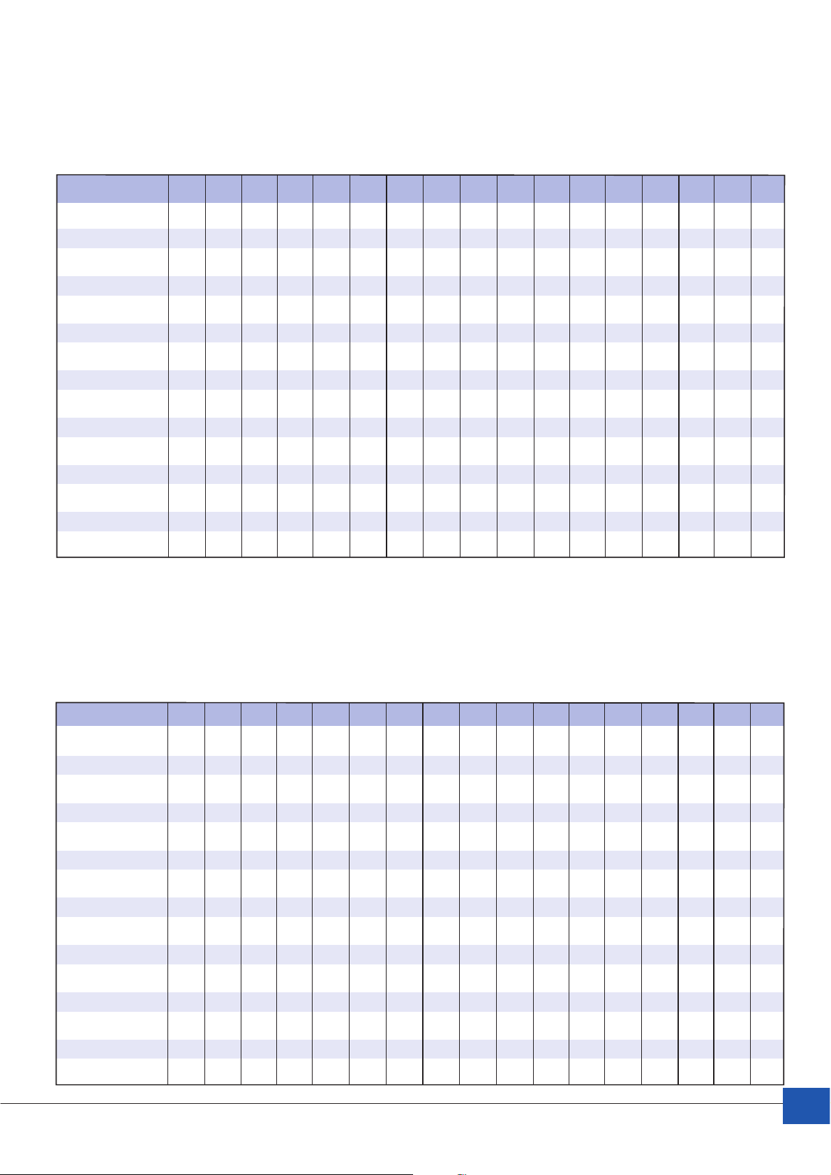
NP Konstantstromentnahme (Ampère) bei 1,65 V/Zelle Entladeschlußspannung (in Minuten/Stunden) bei 20°C
NP Constant Current Drain (Ampères) to 1.65 V/cell cut-off voltage (in minutes/hours) at 20°C
Autonomie in Minuten
Autonomy in minutes
Typ - Type 5 10 15 20 25 30 35 40 45 50 1 2 3 5 8 10 20
NP1-6 2,91 2,20 1,70 1,40 1,15 1,02 0,90 0,83 0,75 0,71 0,62 0,37 0,27 0,17 0,12 0,10 0,05
NP1.2-6 / NP1.2-12 3,60 2,60 2,00 1,60 1,40 1,22 1,10 1,00 0,90 0,85 0,74 0,44 0,32 0,21 0,14 0,12 0,06
NP3-6 8,72 6,09 4,80 4,00 3,45 3,06 2,70 2,48 2,25 2,12 1,85 1,09 0,80 0,52 0,35 0,29 0,15
NP4-6 / NP4-12 12,2 8,70 6,60 5,50 4,70 4,10 3,70 3,31 3,00 2,83 2,50 1,50 1,10 0,70 0,48 0,39 0,21
NP7-6 / NP7-12 21,2 15,2 11,6 9,60 8,10 7,14 6,40 5,79 5,20 4,95 4,40 2,56 1,86 1,22 0,82 0,68 0,36
NP10-6 30,5 21,8 16,7 13,7 11,6 10,2 9,10 8,26 7,50 7,07 6,15 3,65 2,65 1,80 1,17 0,97 0,52
NP12-6 / NP12-12 36,5 26,0 20,0 16,4 13,9 12,2 10,9 9,92 9,00 8,48 7,39 4,40 3,18 2,10 1,40 1,20 0,66
NP0.8-12 2,50 1,80 1,40 1,10 0,94 0,82 0,74 0,68 0,60 0,57 0,49 0,31 0,21 0,16 0,94 0,08 0,04
NP2-12 6,10 4,30 3,30 2,67 2,30 2,04 1,70 1,65 1,50 1,41 1,30 0,76 0,55 0,35 0,25 0,19 0,11
NP2.3-12 7,00 5,00 3,80 3,20 2,70 2,35 2,10 1,90 1,80 1,63 1,42 0,90 0,61 0,40 0,27 0,22 0,12
NP3.2-12 9,80 6,90 5,30 4,40 3,68 3,27 2,90 2,65 2,40 2,26 1,97 1,20 0,89 0,56 0,37 0,31 0,17
NP17-12I 52,6 37,1 27,4 23,3 19,7 17,3 15,4 14,1 12,8 12,0 10,5 6,20 4,60 2,97 2,10 1,65 0,89
NP24-12I 70,6 49,0 38,4 32,0 27,8 24,5 21,8 19,8 18,1 17,0 14,8 8,76 6,37 4,20 2,81 2,40 1,24
NP38-12I 112 77,5 60,8 50,7 43,7 38,8 34,4 31,4 28,5 26,9 23,4 13,9 10,1 6,64 4,45 3,80 1,96
NP65-12I 191 133 104 86,7 75,3 66,3 58,9 53,7 48,6 45,9 40,1 23,7 17,2 11,4 7,61 6,50 3,35
Autonomie in Stunden
Autonomy in hours
NP Konstantstromentnahme (Ampère) bei 1,70 V/Zelle Entladeschlußspannung (in Minuten/Stunden) bei 20°C
NP Constant Current Drain (Ampères) to 1.70 V/cell cut-off voltage (in minutes/hours) at 20°C
Autonomie in Minuten
Autonomy in minutes
Typ - Type 5 101520253035404550 1 2 3 5 8 1020
NP1-6 2,80 1,94 1,54 1,40 1,12 0,99 0,90 0,81 0,74 0,69 0,61 0,36 0,26 0,17 0,11 0,10 0,05
NP1.2-6 / NP1.2-12 3,29 2,40 1,90 1,56 1,35 1,19 1,10 0,97 0,88 0,83 0,73 0,43 0,31 0,21 0,14 0,11 0,06
NP3-6 8,22 5,83 4,62 3,90 3,37 2,97 2,70 2,43 2,22 2,08 1,82 1,08 0,78 0,51 0,34 0,29 0,15
NP4-6 / NP4-12 11,2 7,77 6,30 5,40 4,60 3,96 3,60 3,30 2,90 2,78 2,42 1,50 1,04 0,68 0,46 0,38 0,20
NP7-6 / NP7-12 19,5 13,6 10,8 9,40 7,87 6,93 6,30 5,67 5,10 4,86 4,30 2,60 1,82 1,20 0,81 0,67 0,35
NP10-6 28,0 20,0 15,4 13,5 11,2 9,90 9,00 8,20 7,30 6,94 6,10 3,60 2,60 1,71 1,15 0,95 0,51
NP12-6 / NP12-12 33,5 24,0 19,0 16,1 13,6 11,9 10,8 9,80 8,80 8,33 7,30 4,32 3,12 2,05 1,38 1,14 0,61
NP0.8-12 2,30 1,55 1,30 1,10 0,90 0,79 0,74 0,68 0,57 0,56 0,49 0,29 0,21 0,15 0,09 0,08 0,04
NP2-12 5,60 3,88 3,20 2,60 2,25 1,98 1,70 1,62 1,50 1,39 1,21 0,75 0,54 0,34 0,23 0,19 0,10
NP2.3-12 6,50 4,60 3,60 3,10 2,58 2,30 2,10 1,86 1,58 1,60 1,39 0,90 0,60 0,39 0,26 0,22 0,12
NP3.2-12 8,76 6,40 4,92 4,30 3,60 3,17 2,80 2,59 2,30 2,22 1,94 1,20 0,87 0,55 0,39 0,31 0,16
NP17-12I 47,6 34,0 26,9 22,9 19,2 16,8 15,3 13,9 12,5 11,8 10,3 6,12 4,50 2,91 1,95 1,62 0,86
NP24-12I 66,7 46,6 36,9 31,2 27,3 24,0 21,6 19,4 17,6 16,7 14,6 8,63 6,24 4,10 2,76 2,39 1,21
NP38-12I 106 73,8 58,5 49,4 43,2 38,0 34,1 30,8 27,9 26,4 23,0 13,7 9,90 6,50 4,37 3,78 1,92
NP65-12I 181 126 100 84,4 73,9 65,0 58,2 52,6 47,9 45,1 39,4 23,4 16,9 11,1 7,48 6,47 3,28
Autonomie in Stunden
Autonomy in hours
YUASA Battery (EUROPE) GmbH
11
Page 12
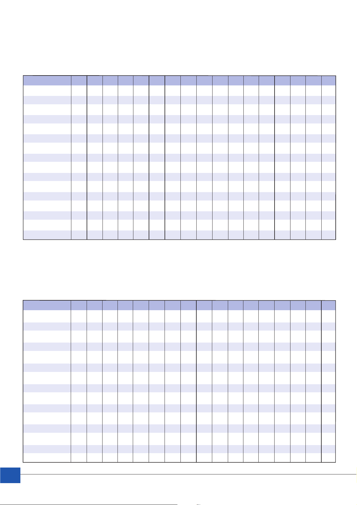
NP Konstantstromentnahme (Ampère) bei 1,75 V/Zelle Entladeschlußspannung (in Minuten/Stunden) bei 20°C
NP Constant Current Drain (Ampères) to 1.75 V/cell cut-off voltage (in minutes/hours) at 20°C
Autonomie in Minuten
Autonomy in minutes
Typ - Type 5 10 15 20 25 30 35 40 45 50 1 2 3 5 8 10 20
NP1-6 2,58 2,00 1,47 1,24 1,07 0,95 0,85 0,78 0,73 0,66 0,58 0,36 0,26 0,16 0,11 0,09 0,05
NP1.2-6 / NP1.2-12 3,09 2,40 1,90 1,48 1,28 1,20 1,10 0,95 0,83 0,80 0,70 0,40 0,30 0,20 0,13 0,11 0,06
NP3-6 7,73 5,56 4,41 3,70 3,21 2,86 2,55 2,34 2,19 1,99 1,74 1,01 0,75 0,49 0,33 0,28 0,15
NP4-6 10,4 7,80 6,20 5,20 4,40 3,90 3,50 3,20 2,80 2,65 2,40 1,40 1,00 0,66 0,46 0,37 0,20
NP7-6 / NP7-12 18,2 13,6 11,0 9,00 7,70 6,67 6,10 5,60 5,00 4,64 4,20 2,50 1,80 1,15 0,78 0,65 0,35
NP10-6 25,8 19,5 15,5 12,9 11,1 9,70 8,80 7,81 7,10 6,62 6,00 3,50 2,60 1,65 1,11 0,93 0,50
NP12-6 / NP12-12 31,3 23,4 18,6 15,5 13,3 11,6 10,5 9,60 8,60 7,95 7,20 4,02 3,11 1,98 1,33 1,11 0,60
NP0.8-12 2,06 1,48 1,30 0,99 0,86 0,76 0,71 0,63 0,57 0,53 0,47 0,27 0,20 0,15 0,09 0,08 0,04
NP2-12 5,16 3,90 3,20 2,47 2,30 2,00 1,70 1,56 1,40 1,33 1,16 0,74 0,53 0,33 0,22 0,19 0,11
NP2.3-12 5,92 4,50 3,60 3,00 2,60 2,30 2,00 1,90 1,60 1,52 1,40 0,77 0,58 0,38 0,26 0,21 0,12
NP2.8-12 7,26 5,50 4,30 3,70 3,00 2,67 2,50 2,30 2,00 1,85 1,70 0,97 0,70 0,46 0,33 0,26 0,14
NP3.2-12 8,40 6,30 4,90 4,20 3,60 3,10 2,80 2,60 2,30 2,12 2,00 1,10 0,86 0,53 0,38 0,30 0,16
NP17-12I 44,3 33,1 26,3 21,9 18,8 16,4 14,8 13,6 12,1 11,3 9,86 6,00 4,40 2,80 1,88 1,57 0,87
NP24-12I 61,9 44,4 35,3 29,6 26,7 22,9 21,1 18,8 17,1 15,9 14,1 8,14 6,00 3,95 2,66 2,38 1,20
NP38-12I 97,9 70,4 55,9 46,9 42,1 36,2 33,3 29,7 27,2 25,2 22,0 12,9 9,50 6,26 4,21 3,76 1,90
NP65-12I 168 120 95,6 80,3 71,9 61,9 57,1 50,8 46,5 43,1 38,2 21,8 16,3 10,7 7,20 6,44 3,25
Autonomie in Stunden
Autonomy in hours
NP Konstantstromentnahme (Ampère) bei 1,80 V/Zelle Entladeschlußspannung (in Minuten/Stunden) bei 20°C
NP Constant Current Drain (Ampères) to 1.80 V/cell cut-off voltage (in minutes/hours) at 20°C
Autonomie in Minuten
Autonomy in minutes
Typ - Type 5 10 15 20 25 30 35 40 45 50 1 2 3 5 8 10 20
NP1-6 2,60 1,77 1,41 1,18 1,10 1,00 0,85 0,75 0,68 0,63 0,56 0,36 0,26 0,16 0,11 0,09 0,05
NP1.2-6 / NP1.2-12 2,93 2,20 1,69 1,50 1,30 1,20 1,00 0,90 0,84 0,76 0,68 0,40 0,29 0,19 0,13 0,11 0,06
NP3-6 7,32 5,31 4,23 3,53 3,06 2,73 2,55 2,24 2,04 1,90 1,67 1,09 0,79 0,52 0,35 0,29 0,15
NP4-6 / NP4-12 9,90 7,40 5,63 5,00 4,30 3,80 3,40 2,99 2,80 2,53 2,22 1,40 0,96 0,70 0,44 0,35 0,19
NP7-6 / NP7-12 17,4 13,0 9,86 8,70 7,40 6,70 6,14 5,40 4,80 4,43 3,89 2,39 1,69 1,11 0,76 0,62 0,35
NP10-6 24,8 18,6 14,1 12,4 10,7 9,50 8,50 7,71 6,90 6,33 5,56 3,33 2,49 1,59 1,07 0,92 0,48
NP12-6 / NP12-12 29,8 22,3 16,9 14,8 12,8 11,4 10,2 9,20 8,30 7,60 6,80 4,10 2,89 1,91 1,28 1,10 0,57
NP0.8-12 1,95 1,46 1,13 0,94 0,86 0,80 0,70 0,60 0,57 0,51 0,47 0,27 0,19 0,15 0,09 0,07 0,04
NP2-12 4,88 3,69 2,82 2,35 2,10 1,90 1,70 1,49 1,40 1,27 1,20 0,74 0,48 0,32 0,21 0,18 0,10
NP2.3-12 5,61 4,30 3,29 2,71 2,35 2,20 2,00 1,80 1,60 1,46 1,28 0,77 0,55 0,37 0,25 0,20 0,11
NP3.2-12 7,85 5,90 4,51 3,90 3,40 3,10 2,70 2,50 2,20 2,03 1,78 1,10 0,77 0,51 0,37 0,29 0,15
NP17-12I 42,2 31,6 23,9 21,1 18,1 16,1 14,5 13,1 11,8 10,8 9,60 5,80 4,30 2,70 1,82 1,50 0,85
NP24-12I 58,5 42,5 33,8 28,2 25,6 21,8 20,5 17,9 16,6 15,2 13,3 8,00 5,78 3,82 2,57 2,36 1,14
NP38-12I 92,7 67,9 53,5 44,7 40,5 34,6 32,4 28,4 26,4 24,1 21,1 12,7 9,40 6,03 4,06 3,36 1,81
NP65-12I 159 116 91,6 76,5 69,4 59,1 54,5 48,5 45,1 41,1 36,1 21,7 15,7 10,3 6,95 6,40 3,26
Autonomie in Stunden
Autonomy in hours
12
YUASA Battery (EUROPE) GmbH
Page 13
Installations-, Behandlungs- und Wartungsvorschriften – Installation, Commissioning and Maintenance Guide
1.0 Lagerung – Storage
Falls die Batterien nicht sofort installiert und in Betrieb genommen werden sollen, ist es empfehlenswert, die Batterien in
den Kartons zu belassen und an einem kühlen, sauberen und trockenen Ort zu lagern. Bei einer Lagerung über 6-9 Monate
ab Produktionsdatum können die Batterien durch eine Ergänzungsladung auf ihre volle Kapazität aufgeladen werden.
If the batteries are not to be installed immediately, keep them boxed and stored in a cool, clean and dry place.
If the batteries are to be stored for six months or more from date of production, a supplementary charge can be carried
out to restore their full capacity.
2.0 Sichtkontrolle bei Entnahme – Unpacking and Inspection
Vorsicht: Batterien sind elektrochemisch permanent aktiv und spannungsführend – verbinden Sie daher nicht die Batteriepole
direkt oder überbrücken Sie diese nie ohne Lastwiderstand.
Überprüfen Sie jede Batterielieferung in Bezug auf Transportschäden. Stellen Sie sicher, daß die Lieferung alle Gegenstände
umfaßt, die auf dem Lieferschein oder auf der Rechnung aufgeführt sind, wie z. B. Verbinder, Abdeckkappen etc.
Entnehmen Sie jede Batterie vorsichtig und achten Sie darauf, daß die Batteriepole nicht beschädigt werden. Prüfen Sie
jede Batterie auf mechanische Beschädigung wie Risse oder Deformationen des Batteriegehäuses oder der Batteriepole.
Messen Sie die offene Klemmenspannung, die pro Zelle über 2,1V liegen sollte.
Danger: Batteries are electrochemically live at all times. Do not short circuit the battery terminals.
Inspect the battery consignment for signs of transport damage. Ensure the consignment has all items listed on the delivery
note or invoice, i.e. batteries, cables, shrouds etc.
While unpacking each battery, take care not to drop anything on the terminals. Inspect each battery for physical damage such
as cracks or distortion of the case and terminals.
Measure the battery open circuit terminal voltage which should be > 2.1 Volt/cell o.c.v.
3.0 Ergänzungsladung – Supplementary charge
Um eine optimale Gebrauchsdauer zu erzielen, sollte vor Inbetriebnahme eine Ergänzungsladung bei einer offenen
Klemmenspannung kleiner als 2,1 V/Zelle erfolgen.
To ensure maximum service life, a supplementary charge should be carried out if the open circuit voltage is less than 2.1
Volts per cell.
Führen Sie die Ergänzungsladung gemäß folgender Tabelle durch:
A supplementary charge should be applied in accordance with figures shown in the table below:
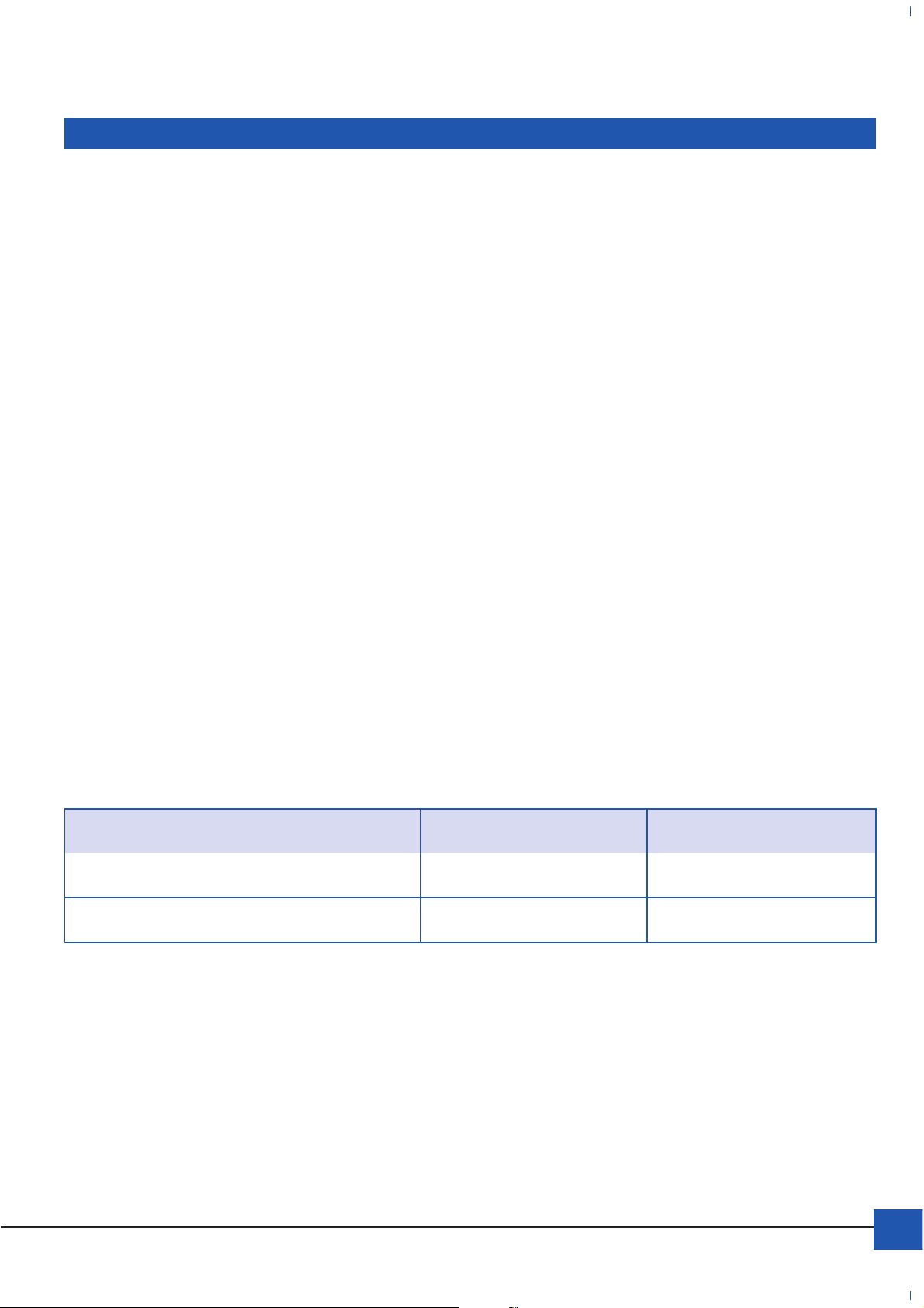
Ergänzungsladung NP – Supplementary charge for the NP Battery range
Lagerdauer in Bezug auf Produktionsdatum Ladespannung/Zelle Ladezeit
Storage Period Charge Voltage per Cell Charge Time
weniger als 1 Jahr 2,275 V/Zelle länger als 72 Stunden
less than 1 year 2,275V/cell more than 72 hours
12 Monate und länger 2,35 V/Zelle mind. 48 Std; max. 144 Std.
1 year and more 2,35 V/cell 48 to 144 hours
Nach erfolgter Ladung prüfen Sie bitte die offene Klemmenspannung, die nach dem Ende des Ladevorgangs über 2,15
Volt/Zelle innerhalb 24 Stunden liegen sollte. Falls dieser Wert nicht erreicht wird, sollte die Batterie einmal entladen und
wieder aufgeladen werden.
After completion of charging, please check that the battery open circuit voltage is above 2,15 Volts / cell within 24 hours from
the end of charge. If not, one discharge/charge cycle will improve o.c.v. performance.
YUASA Battery (EUROPE) GmbH
13
Page 14
4.0 Check-Liste vor der Installation – Pre-installation Check list
Vorsicht: Batterien dürfen nicht in abgeschlossenen Behältnissen betrieben werden.
Sorgen Sie für eine ausreichende Belüftung gemäß EN50272-2:2001.
Zu beachten: Eine permanente Batterietemperatur über 20°C reduziert die Gebrauchsdauer (siehe dazu Tabelle Abschnitt 5.1.)
Danger: Batteries must not be installed in a sealed container.
Please check for sufficient ventilation according to EN 50272-2:2001.
A battery operational temperature of more than 20°C reduces the service life (see table in section 5.1.).
4.1. Installation – Installation
Verwenden Sie einen Drehmomentschlüssel zur Montage der Blockverbinder. Stellen Sie das Drehmoment gemäß Tabelle
4.3 ein. Arbeiten Sie nur mit isoliertem Werkzeug! Beim Hantieren mit Batterien empfiehlt sich das Ablegen jeglichen Schmucks,
Uhren und Ringen. Bei der Installation muss ein Luftspalt von 5-10 mm zwischen den einzelnen Blöcken vorgesehen werden.
Achten Sie auf den Sicherheitsabstand zwischen Batterien und funkenbildenden Betriebsmitteln. Das Batteriegehäuse besteht aus "ABS"-Kunststoff und darf nicht mit organischen Lösungsmitteln oder Klebstoffen in Berührung kommen.
Please use a torque wrench to fasten the connectors onto the battery terminals. The torque should be adjusted according
to the values shown in table 4.3. Please use only insulated tools! Remove all jewellery, watches and rings. If rings cannot be
removed, insulate them with 3 layers of insulating tape. For sufficient installation, a distance of 5-10 mm between the battery
blocks is necessary. Do not install the batteries close to any source of ignition, such as electrical switches or any components
that may produce sparks.
The battery case is made from ABS resin, do not place it in an atmosphere with organic solvents or adhesive material.
4.2 Verbinden von Batterien - Battery Connection
Beim Verbinden von Batterien zu Batteriesträngen gehen Sie bitte methodisch vor. Verbinden Sie den negativen Anschlusspol
einer Batterie mit dem positiven Anschlusspol der nächsten Batterie, und so weiter. Am Ende verbinden Sie die positive und
negative Endableitung mit der Last oder dem Gleichrichter. Zur Parallelschaltung mehrerer Batteriestränge führen Sie
alle positiven Endableiter auf den Pluspol und alle negativen Endableiter auf den Minuspol einer Sammelschiene oder
Klemmleiste. Isolieren Sie alle Batteriepole.
When connecting batteries in a series string, always work methodically. Connect the negative terminal of one battery to the
positive terminal of the next battery, and so on. Finally connect the positive and negative take-off loads to the system load
or rectifier. For parallel connection of several battery strings, connect all positive take-offs to the positive terminal and all
negative take-offs to the negative terminal of a bus bar or terminal block. Ensure all battery terminals are insulated.
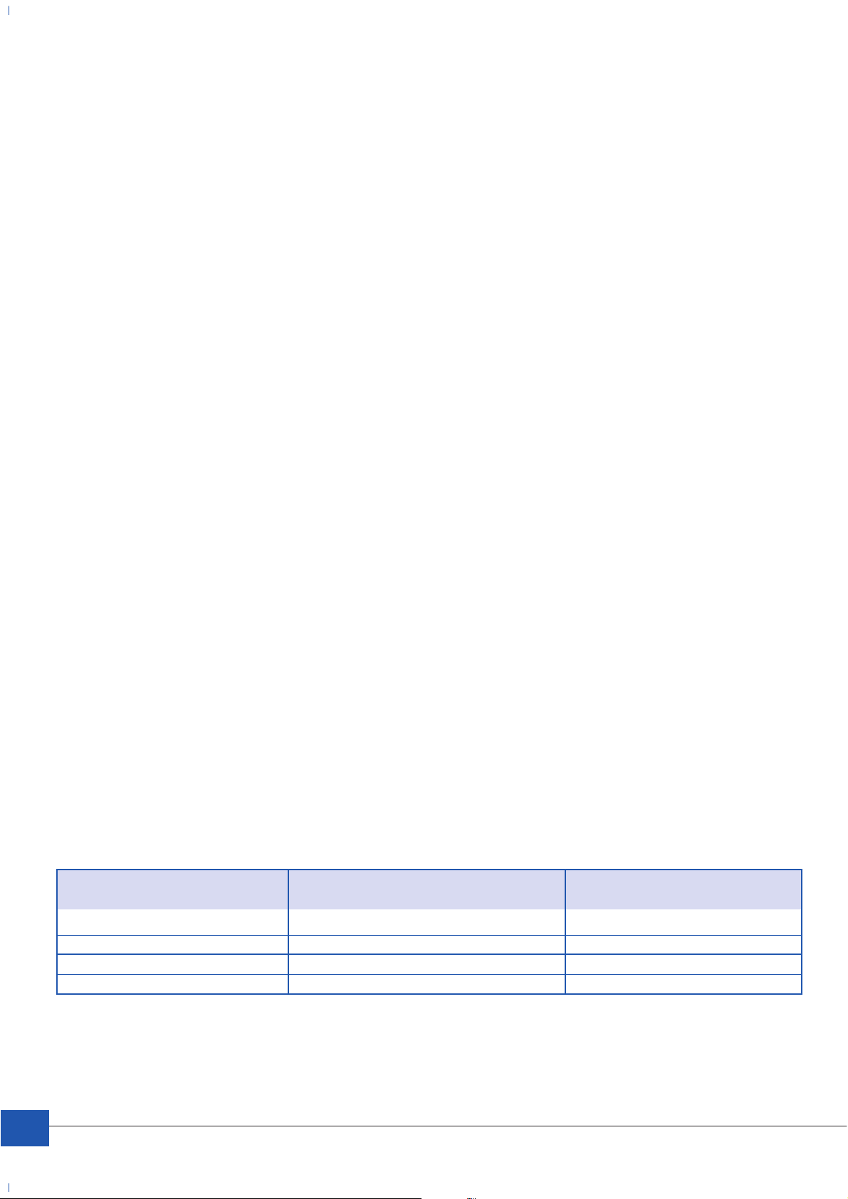
4.3. Drehmomente der Polschrauben – Fastening terminal bolts
Die folgende Tabelle zeigt die optimalen Drehmomente für die Batteriepole.
The following table shows the optimal torque settings for terminal bolts.
Batterie Gewindedurchmesser Drehmoment (Nm)
Battery Bolt Diameter Fastening Torque (Nm)
NP 17 -12I M 5 2-3 Nm
NP 24 -12I M 5 2-3 Nm
NP 38 -12I M 5 2-3 Nm
NP 65 -12I M 6 4-5,5 Nm
Bei starker Überschreitung der o.g. Drehmomente können die Anschlusspole der Batterien zerstört werden.
If the above mentioned torques are exceeded seriously, the battery terminals may be damaged.
14
YUASA Battery (EUROPE) GmbH
Page 15
5.0 Aufladen und Inbetriebnahme – Charging and Commissioning
Nach dem Verschalten der Batterien kann die Ladespannung zugeschaltet werden. Die Schwebeladespannung beträgt 2,275
Volt/Zelle +/-1% bei 20°C. Nach 12-24 Stunden steht die Batteriekapazität zur Verfügung.
After connecting the battery system, the charge voltage can be applied. The float charge voltage is 2,275 V/cell +/-1% at
20°C. The nominal capacity is achieved after 12-24 hours charging.
5.1. Schwebeladespannung, Temperatur und Gebrauchsdauer –
Float charge voltage, Temperature and Design Life
Bei von 20°C abweichenden Batterietemperaturen muss mit -3mV/Zelle/°C kompensiert werden (siehe nachfolgende Tabelle).
Vorsicht: Eine erhöhte Batterietemperatur wirkt sich negativ auf die Gebrauchsdauer unter Schwebeladespannung aus.
If the battery temperature is not 20°C, the charging voltage must be compensated by -3mV/cell/°C (see the table below).
Caution: High operational temperature will have a severely detrimental effect on the battery life.
Batterietemperatur [°C] Schwebeladespannung [V/Zelle] Gebrauchsdauer (unverb.) [Jahre]
Operational Temperature [°C] Float Charge Voltage [V/cell] Expected Battery Life (noncommittal) [years]
0 2,335 5
5 2,320 5
10 2,305 5
15 2,290 5
20 2,275 5
25 2,260 3,5
30 2,245 2,5
35 2,230 1,75
40 2,215 1,25
45 2,200 10 Monate / months
50 2,185 7,5 Monate / months
5.2. Entladeschlußspannung – Setting a Cut-Off Voltage
Bei einer Entladung fällt die Batteriespannung unter ihren Nennwert von 2 Volt pro Zelle. Um einer zu tiefen Entladung und
den daraus resultierenden Schäden entgegen zu wirken, darf die Entladeschlußspannung 1,6 V/Zelle nicht
unterschreiten.
During the discharge, the battery voltage will fall below the nominal value of 2 Volts per cell. In order to prevent over-discharging
and possible damage to the battery, the cut-off voltage must not be below 1.6 Volts per cell.
5.3. AC Ripple Current – effektive Welligkeit des Ladegleichstromes –
AC Ripple Current (the AC component on the DC charge current)
Um eine optimale Gebrauchsdauer der Batterie zu erzielen, sollte die gemessene Welligkeit (R.M.S.) beim Gleichstrom
möglichst gegen „0“ streben und auf jeden Fall kleiner als 0,1 C für Kapazitäten bis zu 17 Ah und kleiner als
0,05 C(A) bei Kapazitäten ab 24 Ah sein.
To obtain maximum service life of the battery, the value of measured AC ripple at R.M.S. on the DC charge current should be Zero
but by no means more than 0,1 C for battery capacities up to 17 Ah and not more than 0,05 C(A) for capacities more than 24 Ah.
6.0 Inspektion und Wartung – Inspection and Maintenance
Um Problemen während des Betriebes vorzubeugen, wird empfohlen, die Batterien alle 6 Monate mit einem Kapazitätstest
zu entladen und wieder voll aufzuladen. Während eines einjährigen Wartungsintervalls sollten die Blockspannungen während
der Ladung und der Spannungsverlauf während der Entladung registriert werden. Den Höchstwert der Batterietemperatur
zwischen den Inspektionen sollte ein Temperaturstreifen festhalten. Im Rahmen einer verlängerten Garantie sind diese und
andere Werte zur Registrierung und Begutachtung YUASA Battery (EUROPE) GmbH Düsseldorf vorzulegen.
Wartungsformblätter sind auf Wunsch erhältlich.
To prevent battery problems, the inspection and maintenance procedures outlined need to be implemented. During annual
service inspections, take and log the voltage readings per battery block and make them accessible to YUASA Battery (EUROPE) GmbH.
This will act as a historical battery system record which will assist in the early detection of possible system problems before
they have a chance to develop (Voltage log sheet on request available from YUASA Battery (EUROPE) GmbH).
7.0 Kundenservice – Customer Service
In Zweifelsfällen und bei sonstigen technischen Fragen wenden Sie sich bitte an den technischen Kundendienst Ihres
Distributors/Händlers oder an YUASA Battery (EUROPE) GmbH: Tel.: +49 / (0) 211/417 90-16 · Fax: +49 / (0) 211/417 90-11
If you have any queries concerning your battery system please contact the technical department of your local distributor/
dealer or YUASA Battery (EUROPE) GmbH: Tel. : +49 / (0) 211/ 417 90-16 · Fax: +49 / (0) 211/ 417 90-11
YUASA Battery (EUROPE) GmbH
15
Page 16

Zu beachten:
1. Die Konstant-Strom- bzw. Konstant-Leistung-Entladedaten der NP Baureihe
beziehen sich auf eine Batterietemperatur von 20°C. Diese Werte sind als nominell
und damit garantiert zu betrachten. Typische Werte übertreffen regelmäßig die
nominellen Werte unter gleichen Bedingungen bei allen Batterietypen und können
bei Bedarf gesondert erfragt werden.
2. Die geschätzte Betriebslebensdauer der NP Baureihe von 3 – 5 Jahren kann unter
den empfohlenen Betriebsbedingungen erzielt werden, wenn dauerhaft eine
Batterietemperatur von 20°C vorherrscht, die Batterie mit einer Schwebeladespannung von 2,275 V/Z ± 1% geladen wird und eine den Konstantladestrom
überlagernde effektive Welligkeit den Wert von 0,05 C(A) nicht überschreitet.
3. Zur Vermeidung eines zu stark ansteigenden Ladestromes bei thermisch bedingter
Absenkung des Innenwiderstandes der Batterie (thermal runaway), der sich ab 30°C
zerstörerisch auf die Batterie auswirken kann, wird empfohlen, bei Temperaturen
über 20°C die Schwebeladespannung um - 3 mV/Zelle/°C abzusenken.
4. In Folge eines ansteigenden Innenwiderstandes der Batterie bei Temperaturen unter
20°C wird empfohlen, die Schwebeladespannung um + 3 mV/Zelle/°C zu erhöhen.
5. Bei Temperaturen höher als 20°C vermindert sich die Lebensdauer der Batterie trotz
temperaturgestützter Spannungskompensation der Schwebeladespannung.
6. Um die optimale Betriebslebensdauer der NP-Baureihe zu erreichen, sind unsere
gesondert erstellten Installations-, Behandlungs- und Inbetriebsetzungsvorschriften
einzuhalten.
To be noted:
1. Constant current and constant power discharge data of the NP series are taken at
20°C battery temperature. These are nominal values and thereby guaranteed. Typical
values regularly exceed the nominal guaranteed ones for all battery types under the
same test conditions and can be readily made available on special request.
2. The estimated service life of the NP series is 3 – 5 years and can be achieved
under recommended service conditions provided that the battery is permanently
kept on float-charge of 2,275 V/cell ± 1% at 20°C and that the ripple current
does not exceed 0,05 C(A).
3. The maximum service life can only be obtained by float-charging at the correct
voltage, which depends on the temperature. Temperature compensation is required
to avoid thermal runaway (at temperatures above 30°C), overcharge at high temperature and undercharge at low temperature.
The recommended temperature compensation factor is -3 mV/cell/°C with reference
to a standard temperature of 20°C.
4. Owing to a rising internal resistance of the batteries at temperatures below 20°C,
it is recommended to increase the float-charge voltage by +3 mV/cell/°C.
5. At temperatures above 20°C service life of the battery will be diminished even if
temperature compensated float-charging is applied.
6. In order to achieve the optimal service life of the NP series, please respect our
installation, operation and maintenance instructions.
YUASA
YUASA BATTERY (EUROPE) GmbH
Wanheimer Straße 47
40472 Düsseldorf · Germany
Tel.: + 49 (0) 2 11/4 17 90-0
Fax: + 49 (0) 2 11/4 17 90-11
[email protected] · www.yuasa.de
Stünings Krefeld · 07/2003
Technische Änderungen vorbehalten. Technical changes reserved.
 Loading...