

Page 1

3D PRINTER
USER MANUAL
INSTALLATION AND SERVICE INSTRUCTIONS,
WARRANTY TERMS AND CONDITIONS
DEERED — USER MANUAL VERSION 2.0
Page 2

Page 3

CONTENT
1. Specifi cations 6
2. Certifi cation 6
3. Safety Precautions 7
3.1 Classifi cations Used 7
3.2 Safety Precautions 8
4. Overview 9
4.1 Description of Printer Components 9
4.2 Safety Components 13
4.3 Accessories 14
5. Material Description and Selection 15
6. Printer Setup 17
6.1 Operating Requirements 17
6.2 Printer Installation 17
6.3 Connecting the Printer to the Network 17
7. Working with the Printer 18
7.1 Working with the Printer Touchscreen – Main Menu Options 18
7.2 Working with the Printer Touchscreen – General Settings 18
7.3 Working with the Printer Touchscreen – Assigning Print Jobs 19
7.4 Working with the Printer Touchscreen – Replacing the Filament 19
7.5 Removing and Inserting the Filament 20
7.6 Preparing the Print Bed 24
8. Printing 25
8.1 Checking and Preparing the Printer 25
8.2 Checking and Preparing the Filament 25
8.3 Checking the Print Bed 25
8.4 Selecting the Print Job 26
8.5 Starting the Printing Process 26
8.6 The Printing Process 26
8.7 Removing the Model 26
DEERED — USER MANUAL 3
Page 4

9. User Servicing and Maintenance 27
9.1 Maintenance 27
9.2 Replacing the Nozzle 28
9.3 Replacing the Print Head 29
9.4 Replacing the Tubing 30
9.5 Replacing the Glass Print Bed 32
9.6 Refi lling the Lubricant 33
9.7 Replacing the Fuses 34
9.8 Resetting the Circuit Breakers 35
9.9 Connecting Peripherals 36
9.10 Periodic proactive maintenance 37
10. Troubleshooting 37
10.1 What to Do If the Printer Runs Out of Filament While Printing and Stops 37
10.2 Removing Supports 38
10.2.1 Insoluble Supports: 38
10.2.2 Soluble Supports: 38
11. Support 39
11.1 Ordering Consumable Materials (Contact and Instructions) 39
11.2 Ordering Consumable Components (Contact and Instructions) 39
11.3 Support and Maintenance in Case You Need Help (Contact and Instructions) 39
12. Warranty Terms and Conditions 39
12.1 The Directive on Liability for Defective Products 39
12.2 Terms and Conditions 39
12.3 Not Covered by the Warranty 40
12.4 User Obligations 40
12.5 Cases in Which the Warranty is Forfeited 40
13. Contact Us 41
DEERED — USER MANUAL 4
Page 5

Meet DeeRed, a professional 3D printer whose print volume and quality meets the
requirements of every demanding designer, manufacturer, or project architect. With
two extruders, a large build volume, and a user-friendly interface, not to mention
high print quality, DeeRed is one of a kind.
The printer’s build volume is one of the largest available in printers using the Fused
Filament Fabrication (FFF) technology, allowing DeeRed to print models up to the
dimensions of 400 x 600 x 800 mm. The printer’s two extruders enable printing
using two diff erent materials or two diff erent colors.
User control is as simple as ever with a large touchscreen and the DeeControl
software, an application that prepares project fi les for 3D layering. DeeControl,
developed by be3D, is available for both Macs and PCs running Windows.
Connect DeeRed to your network via an Ethernet port and monitor the printing
process remotely using the included webcam. Print with a wide array of polymers,
including PLA (polylactic acid), ABS (acrylonitrile butadiene styrene), and PVA
(polyvinyl alcohol). Finally, do not worry about electricity requirements – all the
DeeRed 3D printer needs is a standard power socket.
DEERED — USER MANUAL 5
Page 6

1. SPECIFICATIONS
Print technology FFF
Build volume (X, Y, Z) 600 × 400 × 800 mm
Extruders 2
Print bed heated glass bed
Print accuracy 0.1 mm
Nozzle diameter 0.6 mm
Layer thickness 0.1 / 0.2 / 0.3 mm
Maximum print speed 100 mm/s
Maximum movement speed 200 mm/s
User interface 7” touchscreen
Internal lighting LED
Power supply 100–240 VAC / 50–60 Hz
Input power 120 V / 1.3 kW; 240 V / 2.6 kW
Full dimensions 1150 × 750 × 1950 mm
Weight 250 kg
Connectors LAN, USB (mass storage)
2. CERTIFICATION
§ 15.105 Information to user
NOTE: This equipment has been tested and found to comply with the limits for
a Class B digital device, pursuant to part 15 of the FCC Rules. These limits are
designed to provide reasonable protection against harmful interference in a
residential installation. This equipment generates, uses and can radiate radio
frequency energy and, if not installed and used in accordance with the instructions,
may cause harmful interference to radio communications. However, there is
no guarantee that interference will not occur in a particular installation. If this
equipment does cause harmful interference to radio or television reception, which
can be determined by turning the equipment off and on, the user is encouraged to
try to correct the interference by one or more of the following measures:
• Reorient or relocate the receiving antenna.
• Increase the separation between the equipment and receiver.
• Connect the equipment into an outlet on a circuit diff erent from that to which the
receiver is connected.
• Consult the dealer or an experienced radio/ TV technician for help.
DEERED — USER MANUAL 6
Page 7

3. SAFETY PRECAUTIONS
3.1 Classifi cations Used
Caution
Use heightened caution when working with this device.
Read the manual
Read the User Manual before using this device. Follow the included
instructions.
Unplug the device
Unplug the device from the power source before moving it or using it in
any other way than indicated in the User Manual.
Danger of injury
This device includes moving parts that may cause injury.
Hot components
This device contains components that may be hot and cause injury.
DEERED — USER MANUAL 7
Page 8

3.2 Safety Precautions
• No part of the printer, its accessories, the consumables it uses, or the models
itproduces are intended for consumption.
• Some accessories are sharp, please use heightened caution.
• The user is responsible for any damage to the printer caused by improper
manipulation or use that is in confl ict with the User Manual.
• The printer should not be used by children. It should be used by persons aged 18
and over; in all other cases, the supervision of adults is required.
• Do not leave the printer unattended when in use.
• Some parts of the printer may operate at temperatures higher than 60°C. There
isdanger of burning; avoid contact with hot parts.
• Persons with a physical disability that are unable to use the printer to its full
extent by themselves, can only use it under adult supervision.
• Make sure the printer is complete and does not show any signs of damage
beforeuse.
• Incorrect use may lead to electrical injury.
• The printer is heavy. Do not drop it; failure to observe this may injure the user
ordamage the printer.
• The printer must be disposed of in accordance with environmental law.
• The printer must be kept away from any fl ammable substances.
• The printer generates an electromagnetic fi eld that can infl uence the functionality
of cardiac pacemakers, cochlear implants, and pumps.
DEERED — USER MANUAL 8
Page 9

4. OVERVIEW
v
v
v
v
3
4
7.1
.2
7.3
5
0
9
866.2
6.4
3
6.5
6
.2
2.1
4.1 Description of Printer Components
.1
6.
2
7
1
1. Display
The display is the main component used for interacting with the printer. It carries
out the user’s instructions and reports on the status of the printer and the
processes that are taking place.
DEERED — USER MANUAL 9
Page 10

2. Filament Storage Area
Open the doors of the printer by pushing on the lower part of the frame. This area
is used for storing fi lament spools. Only use fi laments authorized by the printer’s
manufacturer.
2.1. Filament Entry Points
The fi lament storage area contains two fi lament entry points, each for a diff erent
type (or color) of fi lament. Both entry points contain a sensor that detects whether
fi lament has been fed into the feeder tube, as well as detecting whether fi lament
has run out during printing. If this occurs, the printing process is paused and the
user is prompted to end the printing job or to replace the fi lament.
The left fi lament entry point is considered primary. The right fi lament entry point is
considered secondary.
2.2. Spool Holders
The fi lament storage area contains two spool holders. The spool holders have been
constructed to carry a maximum of 2 spools weighing up to 10 kg. Only one spool
may be placed on each spool holder.
3. USB Connector
The USB connector is used for connecting external USB devices to the printer, such
as USB fl ash drives, external USB power supplies, or memory card readers. Please
check with the supplier/manufacturer the compatibility of any USB device not part
of the delivery.
4. Electrical Installation
The electrical installation components are located behind a locked door. The
printer’s power supply, output electronics, and communication bus system are
covered by a metal plate. The visible, uncovered section, contains motor control
units, fuses, and circuit breakers. Do not handle the motor control units when using
the printer.
4.1. Fuses
The fuses protect the low-current circuit of the printer. If a power surge (the
excessive consumption of electric current) occurs, the fuses will blow – this will
generally happen during an overload or in the case of a short circuit. In order for the
printer to become functional again, the fuses must be replaced (see chapter 9.7
“Replacing the Fuses”, on page 34).
4.2. Circuit Breakers
The printer’s wiring is protected by circuit breakers. If a power surge (the excessive
consumption of electric current) occurs, the circuit breakers will be switched off –
this will generally happen during an overload or in the case of a short circuit. In
order for the printer to become functional again, the circuit breakers must be reset
(see chapter 9.8, “Resetting the Circuit Breakers”, on page 35).
DEERED — USER MANUAL 10
Page 11

5. Emergency Power Switch
The emergency power switch is located on the front part of the printer, right under
the display. When switched off , it will immediately turn off the printer. It is primarily
meant to be used in situations that could lead to injury or printer damage.
6. Main Doors/Inside the Printer
The printing area (print chamber) can be accessed through the printer’s main doors.
The doors can be locked; open them by pulling out the lower part of the handle and
turning it 90° clockwise. The doors contain a sensor that detects whether they are
open or closed.
The printing process takes place in the printing area (print chamber). This area may
be hot, so please use caution when opening the main doors. It also contains many
of the printer’s key components.
6.1. Magnetic Locks
The upper and the lower corners of the doorframe contain a magnetic lock, which
stops the door from opening during the printing process and protects the user from
potential injury.
6.2. Print Head
The print head is located on mechanical rails in the upper part of the printing area.
One of the printer’s key components, it is used for layering the fi lament onto the
print bed and then, later, onto the already printed parts of the model. The print head
contains tubing that guides the fi lament into the nozzle, which is located in the
lower part of the print head.
6.3. Waste Chute
The waste chute is located in the right back corner of the printing area and leads to
a wastebasket placed in the printer’s storage area. It has been designed to capture
any waste material produced during the printing process – a spatula, placed on the
edge of the chute, scrapes the nozzle clean every time it passes over it on its way
to the print bed. The removed fi lament then falls through the chute straight into
the wastebasket.
6.4. Print Table
The print table ensures vertical movement during the printing process. The heated
print bed is placed on the upper part on the table; the fi rst layer of the model is
glued to it. The print bed is heated from below and can reach high temperatures (up
to 120 °C), so please use heightened caution when working or coming into contact
with its surface.
To remove the glass bed, loosen the two clips on the front part of the table. Use
caution whenever you come into contact with the print bed.
6.5. Off set Sensor
The off set sensor calibrates the printer before the start of each print job.
DEERED — USER MANUAL 11
Page 12

7. Connectors
The connectors are located on a separate panel on the back of the printer, towards
the right side. When plugging in cables, make sure there is enough space around
the printer for them to drop down naturally – they must not be bent by force. For
safety reasons, the user must have access to the panel with the connectors as
well as to the socket to which the power cable is connected.
7.1. Power Connector with Master Switch
Plug the power cable into the connector to connect the printer to the electricity
network. The connector includes a two-stage switch that can switch the power off
if necessary.
7.2. LAN Connector
The LAN connector enables the user to connect the printer to the local network by
means of an Ethernet cable.
7.3. USB Connector
This connector is identical to the one placed behind the doors to the fi lament
storage area.
8. Grip Insertion Cavities
Insert the provided grips into these threaded cavities to lift and carry the printer.
Ifthe original grips are used, the cavities are able to hold the printer’s weight.
Do not use other grips than those provided by the manufacturer!
9. General Storage Area
The general storage area contains the wastebasket, which catches the waste
material produced during the printing process (the waste falls into the basket
through the waste chute located in the right back corner of the printing area).
Check the wastebasket regularly and empty it when necessary to prevent it from
fi lling up and jamming the waste chute.
The general storage area can also be used for storing tools, materials and printed
models.
10. Rollers/Stands
By default, the printer is delivered with screw-on stands. In the installation process,
however, the stands can be replaced by a set of rollers (the rollers are delivered
together with the printer).
DEERED — USER MANUAL 12
Page 13

4.2 Safety Components
4.2.1 Open Door Sensor
The sensor detects whether the doors to the printing area are open or closed. If
they are open, the printer will not proceed with a print job or start a new one.
4.2.2 Handle with Lock
The handle on the doors to the printing area contains a mechanical lock, which
can only be opened by a key. The key may be used to lock the doors, so that
unauthorized persons cannot access the printing area.
4.2.3 Emergency Power Switch
The emergency power switch is located on the front part of the printer, right under
the display. When switched off , it will immediately turn the printer off . Use it only in
situations that could lead to injury or printer damage.
4.2.4 Print Bed Heating Thermostat
The print bed thermostat is located inside the print table and protects the printer
from overheating and damage. If the print bed temperature exceeds 120 °C, the
thermostat will disconnect the heating unit from the power supply. As soon as the
temperature drops, the thermostat will reconnect the power supply and the heating
unit will start heating up again.
4.2.5 Magnetic Locks
Both the upper and the lower corners of the doorframe contain magnetic locks,
which seal off the printing area until the mechanisms inside have stopped moving
and the temperature of the heated components has dropped to a safe level.
4.2.6 Fuses
The fuses protect the printer’s electronic circuits and will blow in case of a power
surge. In order for the printer to become functional again, the fuses must be
replaced (see chapter 9.7, “Replacing the Fuses”, on page 34).
4.2.7 Circuit Breakers
The printer’s wiring is protected by circuit breakers. If a power surge (the excessive
consumption of electric current) occurs, the circuit breakers will be switched off . In
order for the printer to become functional again, the circuit breakers must be reset
(see chapter 9.8, “Resetting the Circuit Breakers”, on page 35).
DEERED — USER MANUAL 13
Page 14

4.3 Accessories
4.3.1 List of User’s Accessories
Basic Tools
• Set of Allen keys
• be3D tool
Model Processing Tools
• Spatula
• Snipping pliers for small electronics
• Small lineman’s pliers
• Set of scalpels
• Utility knife with a snap-off blade
• Set of small fi les
• Safety glasses
• Safety work gloves
Basic Accessories
• Flash drive (16 GB)
• DeeRed/be3D/Y Soft stickers
• Manuals
• Quick Step poster
• Cards describing service tasks
Consumables
• Filament spools (2.5 kg + 2.5 kg; PLA + PVA)
• Set of spare nozzles (5 pieces + inner tubing)
• Spare set of tubing
• Spare set of fuses: “glass tube fuses”; “fast-blow fuses” 5 A; 6.3 A; 3.15 A
• Glue sticks (10 pieces)
4.3.2 List of DeeRed’s Accessories
• Trash bin
• Shackle (4 pieces)
• Grips (4 pieces)
• Adjustable wheels (4 pieces)
• Adjustable feet (4 pieces)
• Power cable
DEERED — USER MANUAL 14
Page 15
5. MATERIAL DESCRIPTION AND SELECTION
5.1 Material Properties
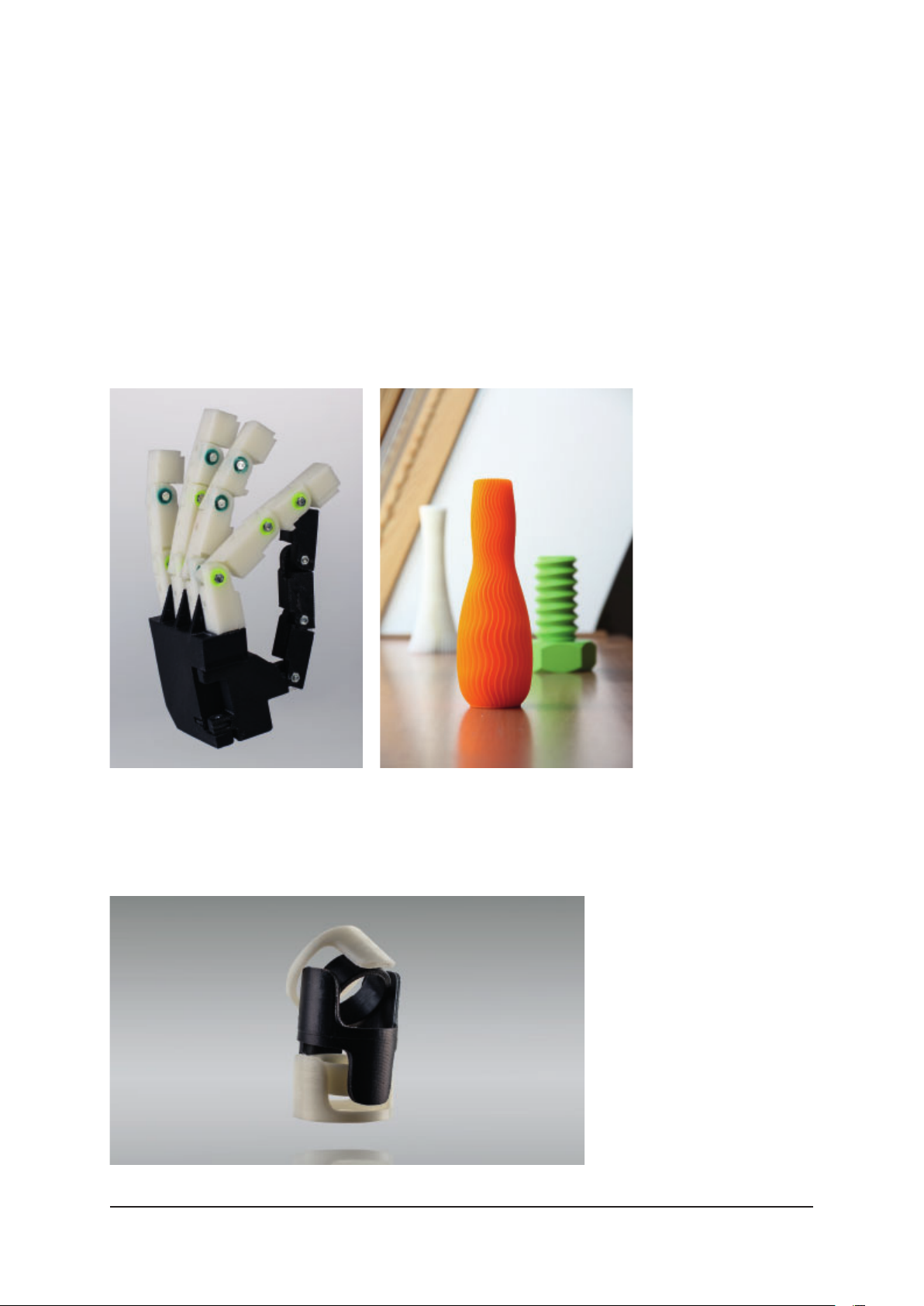
The DeeRed printer supports printing with four basic types of fi lament material. The
properties of each of these fi laments vary considerably.
5.1.1 PLA (Polylactic Acid)
PLA is a basic building material, the fi rmest of the supported types. It is
characterized by a lower thermal resistance, but also produces highly stable prints
in maximal sizes.
PLA is suitable for view models, large models, and models requiring fi rmness.
5.1.2 ABS (Acrylonitrile Butadiene Styrene)
ABS is an industrial plastic material known for being highly resilient and easy to
process. Due to its high level of shrinkage, though, it is not recommended for large
models.
DEERED — USER MANUAL 15
Page 16
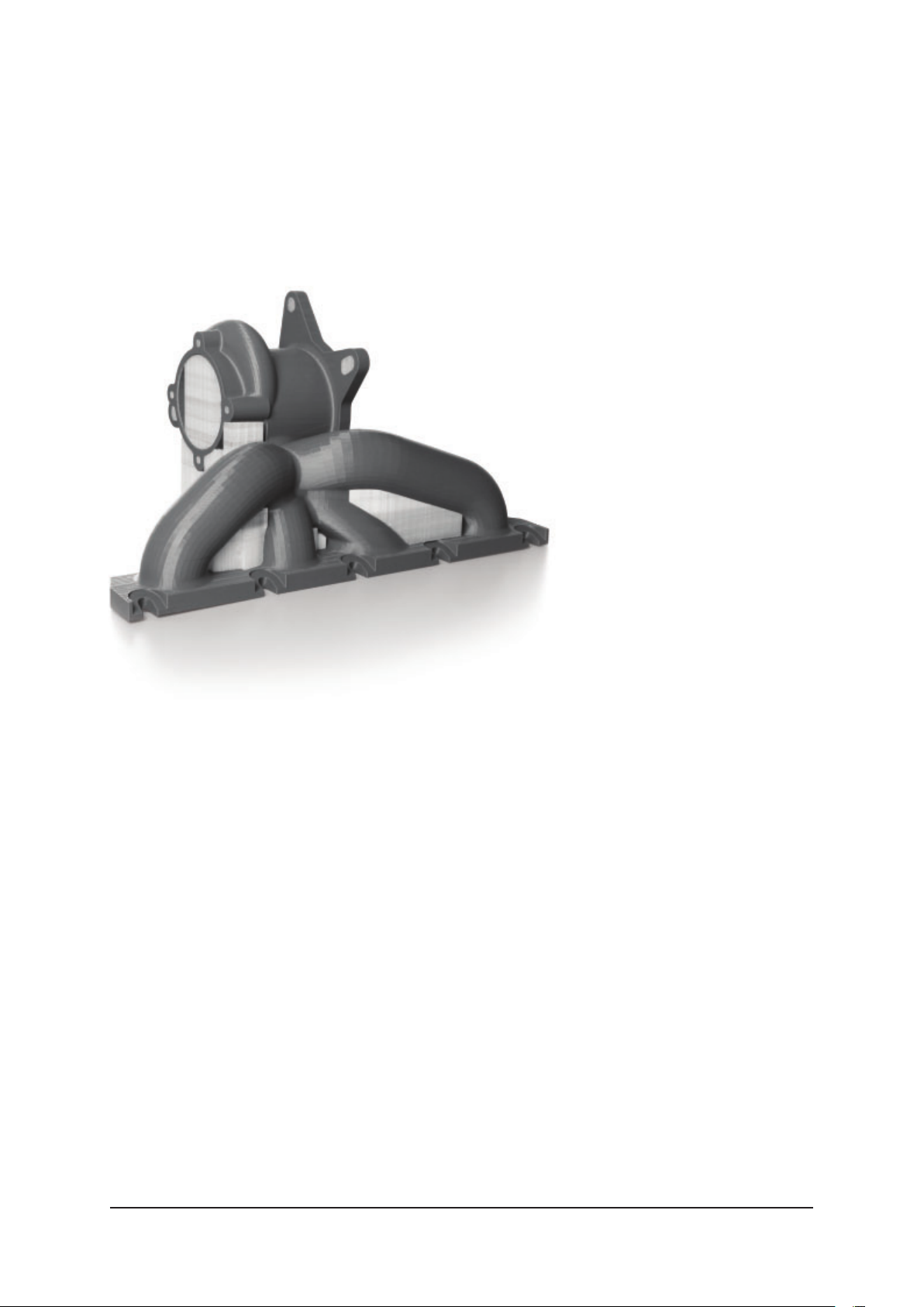
ABS is suitable for models that will be subjected to mechanical stress, models with
a higher heat resistance, and models that require easy surface processing.
5.1.3 PVA (Polyvinyl Alcohol)
A water-soluble fi lament, PVA is used for supports, which can then easily be
removed in a water bath or under a stream of water. PVA’s properties (heat and
others) make it compatible with PLA.
5.1.4 HIPS (High Impact Polystyrene)
HIPS has similar properties to ABS. It is also soluble in a solvent known as
“limonene/lemonade”. So apart from being used as a stand-alone printing material,
itis often used for supports in ABS models.
DEERED — USER MANUAL 16
Page 17

6. PRINTER SETUP
Before the printer is used for the fi rst time, it has to undergo installation. This is
the responsibility of the supplier. As DeeRed off ers high-quality printing, in order for
this service not to be compromised, the user is not allowed to move, lift, or tip the
printer without the assistance of authorized technical support.
6.1 Operating Requirements
■ Operating temperature: 15–25 °C
■ Maximum humidity: 80 %
■ Dust-free environment
■ Firm and stable fl oor (prevents vibration transfer from the surrounding area)
■ Power requirements: 230 V / 2.6 kW or 120 V / 1.3 A
■ Minimal fusing current: 16 A / type B or 15 A
■ The printer must be placed 2 m or more from any heat source
■ Minimal ceiling height: 2.5 m
■ Manipulation and service area around the printer:
Left: 50–80 cm
Right: 50–80 cm
Front: 80–120 cm
Back: 30–70 cm
■ Installation space: 1510 × 1505 × 1950 mm
■ The printer must be placed in a well-ventilated area.
6.2 Printer Installation
Printer installation is carried out by a service technician appointed by the supplier.
6.3 Connecting the Printer to the Network
If the user wants to take advantage of the printer’s network functions, they must
connect it to the network via Ethernet – an Ethernet connector can be found on
the back of the printer (see chapter 4, “Overview”, on page 9). After the printer has
been connected to the network, users can use the DeeControl software to send
print jobs. The software will also display the status of the printer – whether it is
waiting for a print job to load, printing, or otherwise occupied (e.g., updating its
fi rmware).
DEERED — USER MANUAL 17
Page 18
The printer can be automatically confi gured through a DHCP server. In the main
menu, this option is selected as default (see chapter 7.2, “Working with the Printer
Touchscreen – General Settings”, section “Connection Settings”, page 18). If a DHCP
server is not available, the network connection settings can also be confi gured
manually.
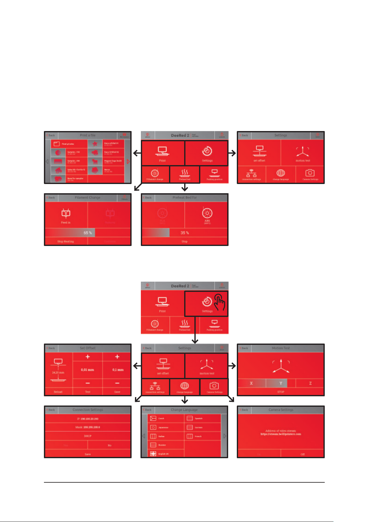
7. WORKING WITH THE PRINTER
7.1 Working with the Printer Touchscreen – Main Menu Options
1
12
34
34
2
7.2 Working with the Printer Touchscreen – General Settings
2
2.1
2.3
2.1
2.3
2.4
2.4
2.2
2.5
2.2
2.5
DEERED — USER MANUAL 18
Page 19
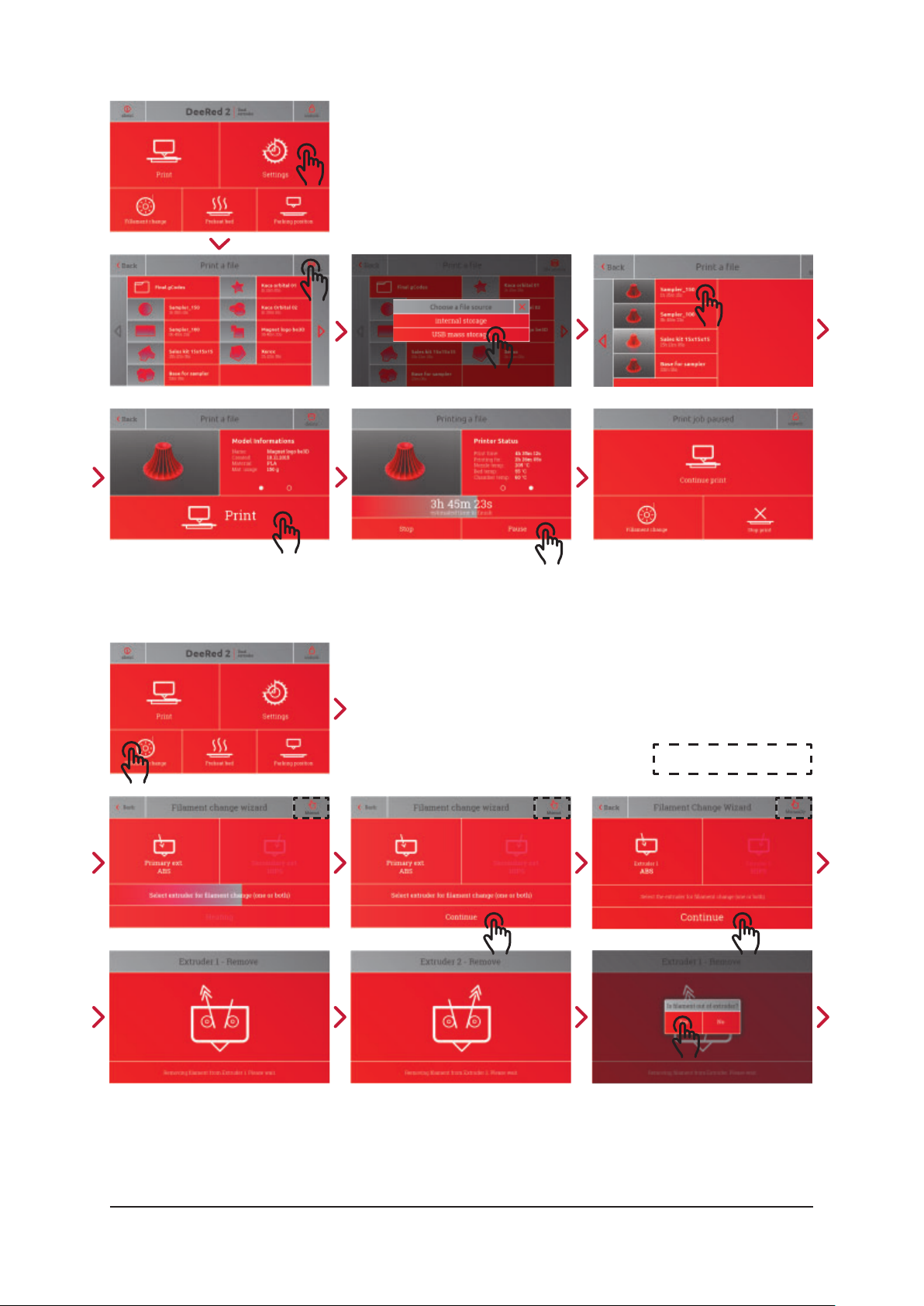
7.3 Working with the Printer Touchscreen – Assigning Print Jobs
7.4 Working with the Printer Touchscreen – Replacing the Filament
OPTIONAL MANUAL MODE
DEERED — USER MANUAL 19
Page 20
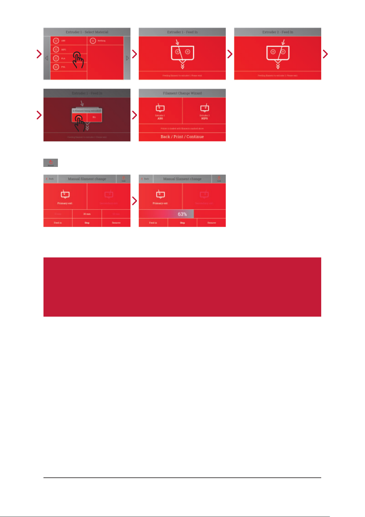
OPTIONAL MANUAL MODE
7.5 Removing and Inserting the Filament
Attention:
To ensure the print head functions correctly during printing it is
necessary to insert both fi laments even though the print job requires
only one fi lament.
1. Press the “Filament Change” button in the main menu on the printer display.
2. The print head will move into the servicing position.
3. The fi lament replacement wizard will appear on the display.
4. For easier use, disconnect the tubing from the print head (see chapter 9.4
“Repalcing the tubing”, page 30)
5. Replacing the Print Head
6. The print head is replaced whenever it needs to be serviced, a replacement is
being claimed for, or when it is being replaced with a diff erent piece or type.
7. Use the screen of the printer (see chapter 7.4, “Working with the Printer
Touchscreen – Replacing the Filament”, page 19) to remove both fi laments from
the printer.
DEERED — USER MANUAL 20
Page 21
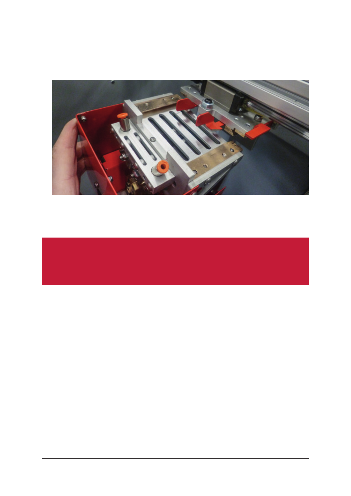
8. Select the “Service Position” button in the “Settings” menu and hold it until
amessage asks you to turn the printer off .
9. Disconnect the tubing from the print head. Press the plastic ring on the mouth
of the print head and, at the same time, pull out the tubing. Repeat the process
for each individual tube.
10. Hold the print head with one hand and pull the security clamps towards you.
Pulling the security clamps will release the print head. Then bring the print head
towards you to release the anchoring mechanism.
Attention:
Take care not to drop the print head after the anchoring mechanism has
been released!
11. When replacing the print head, follow the steps in reverse order.
12. The print head will be secure only when it has been placed on the two dovetail
skids and pushed back as far as possible. The security clamps must face away
from each other.
13. Remember to reconnect the tubing to the mouth of the print head. Take care to
insert the tubing into the correct opening.
14. Replacing the Tubing
Filament Replacement Wizard
1. It is possible to exit the wizard and insert the fi lament manually (press the
button in the top left corner of the screen to activate manual mode). If you opt
to replace the fi laments in manual mode, you risk damaging the print head.
DEERED — USER MANUAL 21
Page 22

2. Remove the fi lament
a. On the fi rst screen of the wizard, select the extruder (or extruders) where
you want the fi lament replaced. If a print job has already been activated, or
if the fi lament is being replaced mid-print, one of the options may already be
selected by default.
b. The selected extruders will now eject the fi lament. Make sure the fi lament
in the print head has been loosened and can be removed completely. To do
this, remove the spool (either empty, or with the remaining fi lament) from the
fi lament storage area and, if necessary, remove the remaining fi lament from
the fi lament entry points.
3. Select the fi lament to be inserted
4. A message will appear on the screen of the printer asking you to select the
fi lament to be inserted into the selected extruder. If a print job has already been
activated, or if the fi lament is being replaced mid-print, one of the options may
already be selected by default.
5. Insert the fi lament
6. Following the instructions on the screen, insert the required fi lament into the
corresponding extruders.
7. To insert the fi lament, place the fi lament spool on the spool holder and feed the
fi lament into the corresponding entry point. Push the fi lament with your fi ngers
until its end passes through the tubing and enters the print head. Once in the
print head, the fi lament will be picked up by the extruder.
8. Let the fi lament pass through the printer until the nozzle ejects molten plastic in
the correct color.
9. Confi rm and exit the wizard
10. The screen will indicate the type of fi lament that has been fed into each
extruder. If you have inserted a type of fi lament other than indicated, the entire
fi lament replacement process will have to be repeated.
DEERED — USER MANUAL 22
Page 23

Manual Mode
Attention:
Be extremely cautious when working in manual mode. Inserting the
fi lament incorrectly or selecting an incorrect fi lament type may cause
damage to the printer or its components.
1. Removing the fi lament
a. Wait for the nozzle to heat up.
b. Select the extruder where you want to replace the fi lament and press “80mm”.
c. Press “Remove”.
d. The material may be extracted sooner. You can stop the process at any time
by pressing “Stop”.
e. Repeat steps b) to d) with the other extruder.
2. Inserting the fi lament
a. Feed the fi laments from the spools in the fi lament storage area into the
respective fi lament entry points, so that each fi lament is inserted into the
corresponding extruder.
b. Select the extruder where you want to replace the fi lament and press “30mm”.
c. While gently pushing the fi lament that is being fed into the print head, press
“Feed In”.
d. Keep your hand on the material to make sure it is being fed into the extruder
(the material will be steadily drawn into the print head).
e. To ensure the fi lament has been inserted into the extruder correctly, do not
insert the fi lament by more than 30 mm (from the point when it’s completely
loose).
f. Repeat steps b) to e) for the other extruder.
Attention:
• Feed both fi laments into the corresponding extruders even if only one
of them will be used. Printing will be more reliable.
• Be careful when changing the fi lament. You can burn yourself by
touching the nozzle of print bed by accident.
• Do not touch the molten plastic that is coming out of the nozzle.
Remove it using appropriate equipment, such as a spatula or a pair of
pincers.
DEERED — USER MANUAL 23
Page 24

7.6 Preparing the Print Bed
The print bed can be prepared in various ways, according to diff erent print
requirements, the main diff erence being the adhesives used for diff erent materials.
Considering the fact that a thoroughly prepared print bed will last throughout
several printing cycles, users that switch between printing materials on a regular
basis may benefi t from having several print beds at hand, each prepared for
adiff erent type of material.
ABS and HIPS
The recommended “ABS” solution for these materials is made of concentrated
acetone and ABS granules. Using a brush, spread the solution in a thin layer over
the print bed (do not heat it up!). For maximal adhesion, degrease the print bed
beforehand.
Apply the layers evenly, one by one. When preparing for repeat printing, apply
several thin layers, waiting for each layer to fully dry before applying a new one.
Ifalayer gets damaged, add a new one to the relevant area.
PLA and PVA
To prepare the print bed for these two materials, apply a layer (or, ideally, a double
layer) of PVA-based glue (paper glue) to the glass bed. Use a regular glue stick and
apply the glue to the print bed in one direction, line by line, creating a thin, even
layer. After it has dried, apply a second layer, this time applying the glue stick in
adiff erent direction. When the second layer has also dried, the print bed is ready
for printing. The glue is water-soluble, so do not wash the print bed unless you
want to prepare it for a diff erent type of material
DEERED — USER MANUAL 24
Page 25

8. PRINTING
8.1 Checking and Preparing the Printer
Use the following list to check the printer before printing, especially if you are not
the last person to work with it.
1. Briefl y look the printer over. Make sure it appears complete and is not out of
order (e.g., due to maintenance).
2. Check that the printer is connected to a power source.
3. Check that the emergency power switch is not set to “Off ”.
4. Check that there are no objects in the printing area that are obviously not part
of the printer.
5. Check that the print bed is locked in place.
6. Check that no models or model parts have been left on the print bed.
7. Check that the print head is connected to the printer and secured against
becoming loose.
8. Check that there are no error messages on the printer display.
8.2 Checking and Preparing the Filament
Before starting a print job, always make sure that the fi lament that is being fed into
the printer corresponds to the fi lament for which the print job has been designed
(see chapter 7.3., “Working with the Printer Touchscreen – Assigning Print Jobs”,
section “Model Information”, page 19).
The printer itself cannot determine the type of fi lament that has been fed into it.
Check the fi lament type by looking into the fi lament storage area.
Press “Print” on the display and select the print job you want to print. Display its
details and locate the fi lament type it works with.
If the print job has been designed for a diff erent type of fi lament than the one
inserted in the printer, it is necessary to replace it (see chapter 7.4., “Working with
the Printer Touchscreen – Replacing the Filament, page 19). Alternately, the print job
can also be altered to work with the fi lament that is available.
8.3 Checking the Print Bed
Always check the print bed before printing.
Remove all objects from the bed, both fi nished models and unfi nished model parts.
Then check whether the print bed has been prepared using the correct adhesive
(see chapter 7.6., “Preparing the Print Bed”, page 24).
DEERED — USER MANUAL 25
Page 26

8.4 Selecting the Print Job
Use the printer display to select the desired print job (see chapter 7.3, “Working
with the Printer Touchscreen – Assigning Print Jobs”, page 19). Press “Print”, found
in the main menu. You can use the “File Source” icon in the upper right corner of the
display to select the source of the print job – locate it based on name, parameters,
job details, or model preview.
The print jobs sent to the printer through the network have been saved in the
printer’s internal storage (select “Internal Storage” – see chapter 7.3., “Working with
the Printer Touchscreen – Assigning Print Jobs”, page 19).
8.5 Starting the Printing Process
Before starting the printing process, make sure that the doors of the printer are
closed. Then press “Print” to confi rm the specifi c print job – the printer will now
start printing.
As a fi rst step, the printer will calibrate itself. It will locate all of its mechanical
components and set them to their basic positions, where they will then heat up to
the required printing temperature.
This process can take several minutes.
8.6 The Printing Process
In this step, the printer prints the model. The printing process itself works as
follows: at fi rst, the printer stretches the fi lament that has been fed into it
(incontrolled conditions) and proceeds to melt it. The molten fi lament is then
pushed through the nozzle and onto the print bed; then, as the model gradually
builds up, itis layered onto the layers printed previously.
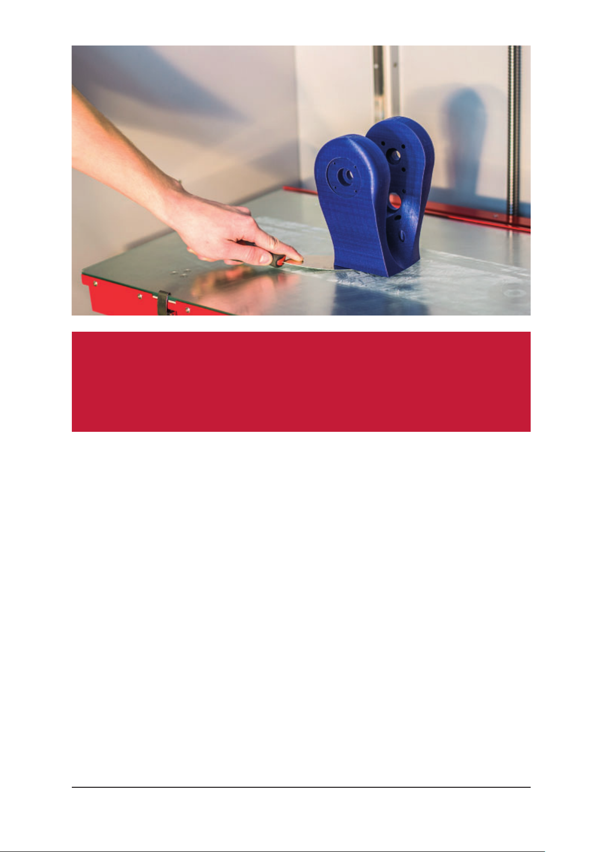
8.7 Removing the Model
When the print job is fi nished, remove the model from the printer. If the model is
not very tall, the print bed will be in the upper part of the printing area – use the
“Parking Position” function to lower it. Then wait for the printer to release the
magnetic locks in the doors and allow access to the printing area. If the print bed
and model are both prepared correctly, the model should be fi rmly glued to the bed.
Wait until the print bed has cooled down to room temperature, then remove the
model using the spatula. Use the tool to gently lift the model’s edges and then push
it underneath the model itself. Pull the spatula out and push it under the model
from a diff erent direction. Repeat the process until you are able to remove the
model from the print bed in one piece easily.
DEERED — USER MANUAL 26
Page 27
Attention:
Depending on the settings of the print job, the inside of the printing
chamber can be hot. Take care when opening the printer’s doors and
entering the printing area.
9. USER SERVICING AND MAINTENANCE
9.1 Maintenance
Keeping the printer clean in order to work long term without malfunctioning is
crucial. It is important to observe the following instructions:
1. Keep the printing area clean. Clean it regularly using a brush and a cloth,
removing model fragments, dust and dirt from its fl oor. Do not use sharp objects
that could scratch the surface of the printer.
2. Keep the nozzle clean. If you notice the mouth of the nozzle is clogged, its
surface is dirty, or that it is covered by a layer of printing material, it will be
necessary to clean it. Select the “Service Position” button in the “Settings”
menu and hold it until a message asks you to turn the printer off . Clean the
nozzle with a snap-off knife or another sharp metal tool, moving it downwards
along the surface of the nozzle. Remove any remnants clogging the nozzle’s
mouth with pliers or something similar.
DEERED — USER MANUAL 27
Page 28
3. Regularly check the amount of waste in the wastebasket placed in the printer’s
storage area. If the basket starts fi lling up, remove it and empty it. Do not forget
to return it to its place so that any waste produced by the printer will not fall
into the general storage area.
Attention:
Always turn the printer off before carrying out any type of hardware user
maintenance.
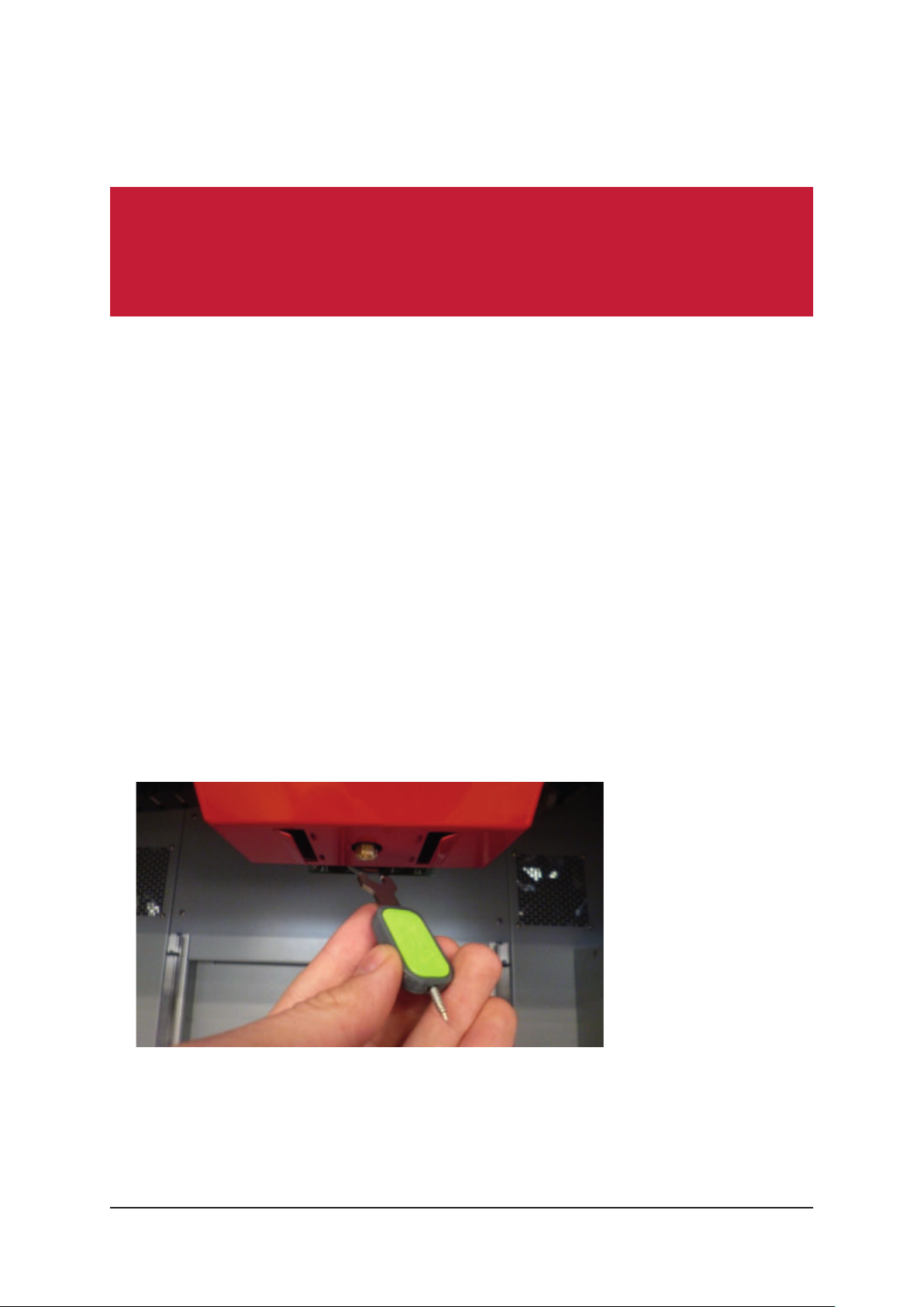
9.2 Replacing the Nozzle
If the printer is unable to push the molten fi lament evenly and continuously through
the nozzle, the nozzle must be replaced. First of all, carry out the following steps:
1. Use the screen of the printer (see chapter 7.4, “Working with the Printer
Touchscreen – Replacing the Filament”, page 19) to remove both fi laments from
the printer.
2. Select the “Service Position” button in the “Settings” menu and hold it until a
message asks you to turn the printer off .
3. Disconnect the tubing from the print head. Press the plastic ring on the mouth
of the print head and, at the same time, pull the tubing out. Repeat the process
for each individual tube.
4. If the nozzle is hot, wait for it to cool down.
5. Using a small knife or another sharp object, remove the silicon gasket from the
nozzle.
6. Remove the nozzle using the “be3D tool” wrench.
7. Insert the screw of the “be3D tool” into the opening where the nozzle had been
placed and screw it in.
DEERED — USER MANUAL 28
Page 29
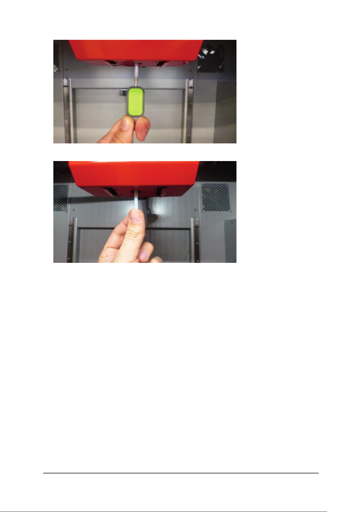
8. Drag the “be3D tool” downwards – this will remove the tubing from the opening;
9. Insert new tubing into the original opening and push it completely in.
10. Screw the new nozzle on and tighten it using the wrench.
11. Place the silicon gasket on the nozzle so that its lower rim does not extend
beyond the nozzle’s edge. The gasket must fi ll the space between the nozzle
and the metal cover of the print head.
9.3 Replacing the Print Head
The print head is replaced whenever it needs to be serviced, a replacement is being
claimed for, or when it is being replaced with a diff erent piece or type.
1. Use the screen of the printer (see chapter 7.4, “Working with the Printer
Touchscreen – Replacing the Filament”, page 19) to remove both fi laments from
the printer.
2. Select the “Service Position” button in the “Settings” menu and hold it until a
message asks you to turn the printer off .
3. Disconnect the tubing from the print head. Press the plastic ring on the mouth
of the print head and, at the same time, pull out the tubing. Repeat the process
for each individual tube.
DEERED — USER MANUAL 29
Page 30
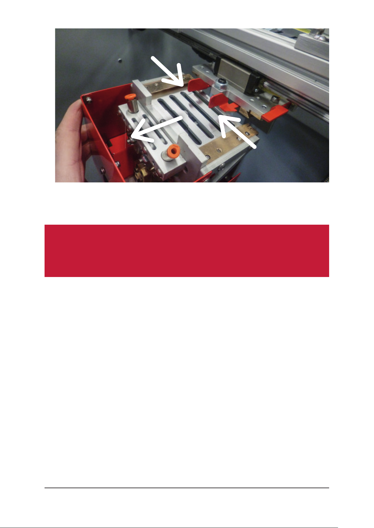
4. Hold the print head with one hand and pull the security clamps towards you.
Pulling the security clamps will release the print head. Then bring the print head
towards you to release the anchoring mechanism.
Attention:
Take care not to drop the print head after the anchoring mechanism has
been released!
5. When replacing the print head, follow the steps in reverse order.
6. The print head will be secure only when it has been placed on the two dovetail
skids and pushed back as far as possible. The security clamps must face away
from each other.
7. Remember to reconnect the tubing to the mouth of the print head. Take care to
insert the tubing into the correct opening.
9.4 Replacing the Tubing
If the printer is unable to evenly and continuously push the molten fi lament through
the tubing, the tubing must be replaced. Carry out the following steps:
1. Use the screen of the printer (see chapter 7.4, “Working with the Printer
Touchscreen – Replacing the Filament”, page 19) to remove both fi laments from
the printer.
DEERED — USER MANUAL 30
Page 31
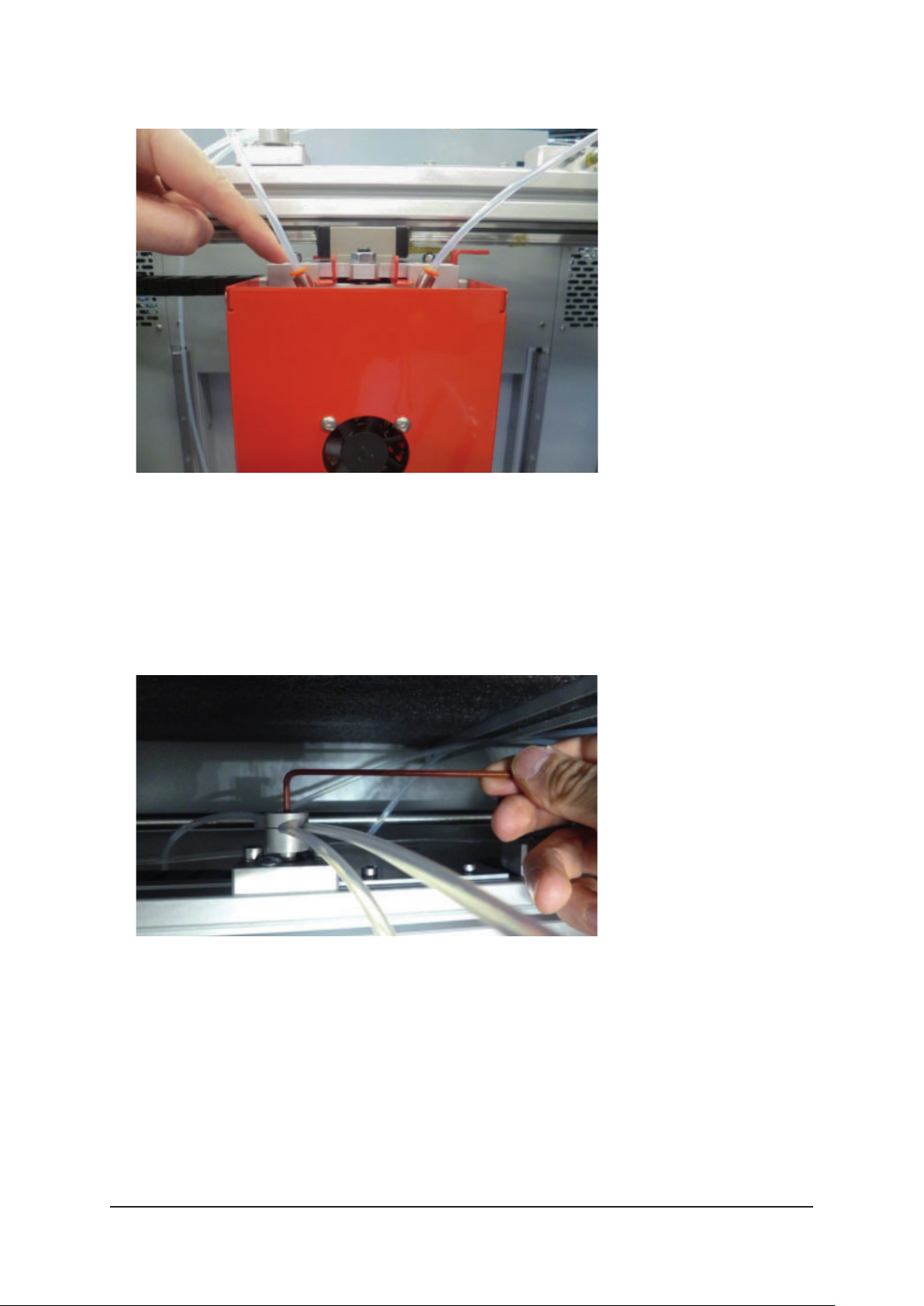
2. Select the “Service Position” button in the “Settings” menu and hold it until
amessage asks you to turn the printer off .
3. Disconnect the tubing from the print head. Press the plastic ring on the mouth
of the print head and, at the same time, pull the tubing out. Repeat the process
for each individual tube.
4. If the nozzle is hot, wait for it to cool down.
5. Detach the tubing from the entry point to the fi lament storage area by pressing
the plastic ring on the opening of the coupling component (connecting piece).
6. Loosen the screw on the rotating holder using a size 2.5 Allen key and remove
both pieces of tubing.
7. Insert the new tubing into the rotating holder – insert the both tubes into the
left and right openings. Adjust the tubes so that their loose length from the
holder to the print head is 42 cm; then secure them by tightening the screw on
the rotating holder.
8. Insert the loose ends of the tubing into the mouth of the print head so that
the left tube is inserted into the left mouth and the right tube into the right
DEERED — USER MANUAL 31
Page 32
one. Gently push the tubing until it settles into each connecting piece. A tube
that has been inserted correctly cannot be removed unless the plastic ring is
pressed.
9. Push the loose ends of the tubing trailing behind the holder through the duct in
the body of the printer and then connect the tubes to the connecting pieces in
the upper right section of the printing area. Connect the tubing in such a way
that the left tube is connected to the front connecting piece and the right tube
is connected to the back connecting piece. Gently pull the ends of the tubes
to make sure that the tubes have been properly inserted into the connecting
pieces and cannot be pulled free.
9.5 Replacing the Glass Print Bed
1. Use the screen of the printer (see chapter 7.4, “Working with the Printer
Touchscreen – Replacing the Filament”, page 19) to remove both fi laments from
the printer.
2. Select the “Service Position” button in the “Settings” menu and hold it until
amessage asks you to turn the printer off .
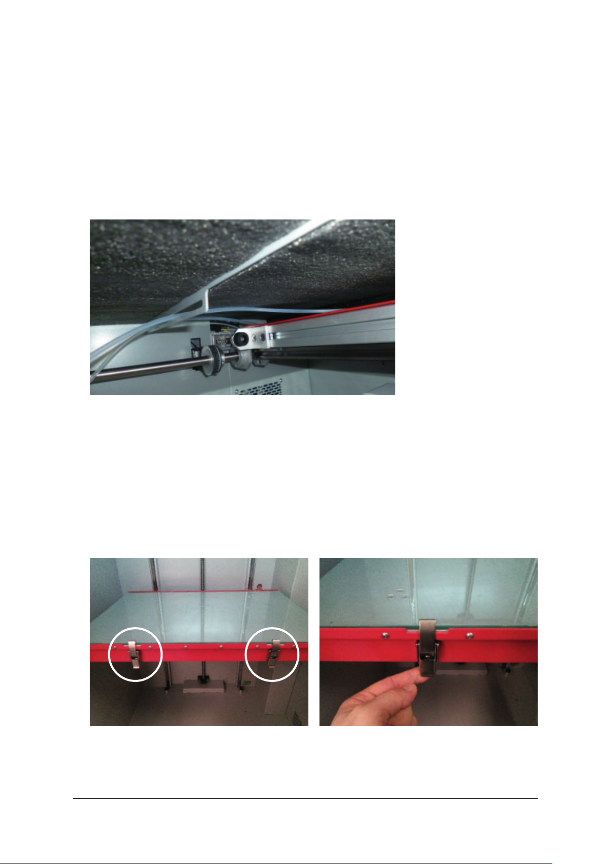
3. The glass bed is kept in place by two clips on the front of the printing table.
DEERED — USER MANUAL 32
Page 33
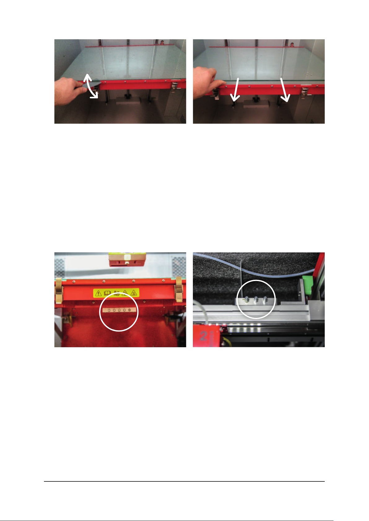
4. Unclamp them.
5. Insert a clean spatula underneath the edge of the glass bed and gently push it
forward in order to let air in between the print bed and the table’s surface.
6. Lift the front edge of the print bed and pull it towards you to loosen the back.
7. Before replacing the print bed, make sure the printing table is clean.
8. To install a diff erent print bed, follow the steps in reverse direction.
9.6 Refi lling the Lubricant
1. Lubricate using only recommended accessories (a grease gun).
2. Use only recommended lubricating grease. If a diff erent type of lubricant is used,
the moving components of the printer can become irreparably damaged.
3. Insert the fi tting of the grease gun into all grease cups placed under the print
table and the load-bearing section of axis X.
4. Press the trigger of the grease gun to lubricate the grease cups. The amount of
lubricant inserted into each grease cup should correspond to one press of the
gun’s trigger. Do not, under any circumstances, insert more lubricant into the
grease cups than indicated above (do not press the trigger several times), as
this could damage the sealing of the carriages of the linear travel.
Recommended lubricant: Lubrication grease HIWIN G0, Cartridge 400 g
Recommended grease gun: GROZ grease gun, one-handed fi llable G5F/PRO/M
DEERED — USER MANUAL 33
Page 34
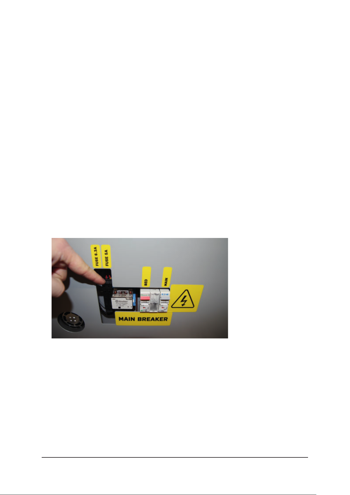
9.7 Replacing the Fuses
Only replace the fuses if the following has occurred:
1. The printer should be working; however, the light in the printing area is off ,
the fans in the back of the printer are not moving, and the display is dark and
unresponsive.
2. Check the following:
I. The emergency power switch is set to “On”.
II. The switch of the power cable connector in set to “On”.
III. The power cable is connected both to the printer and to a power source.
IV. The circuit breakers next to the fuses are set to “On” (see chapter 9.8.,
“Resetting the Circuit Breakers”, page 35).
V. The power socket to which the printer is connected works.
VI. After checking/amending the steps above, the printer still appears not to be
working.
3. Turn the printer off .
4. Use the key that came with the printer to open the printer’s electrical
installation area.
5. Remove the cover of the electrical installation area.
6. Locate the fuse panel.
7. Press the upper lever next to the fi rst fuse slot and fl ip it open.
DEERED — USER MANUAL 34
Page 35
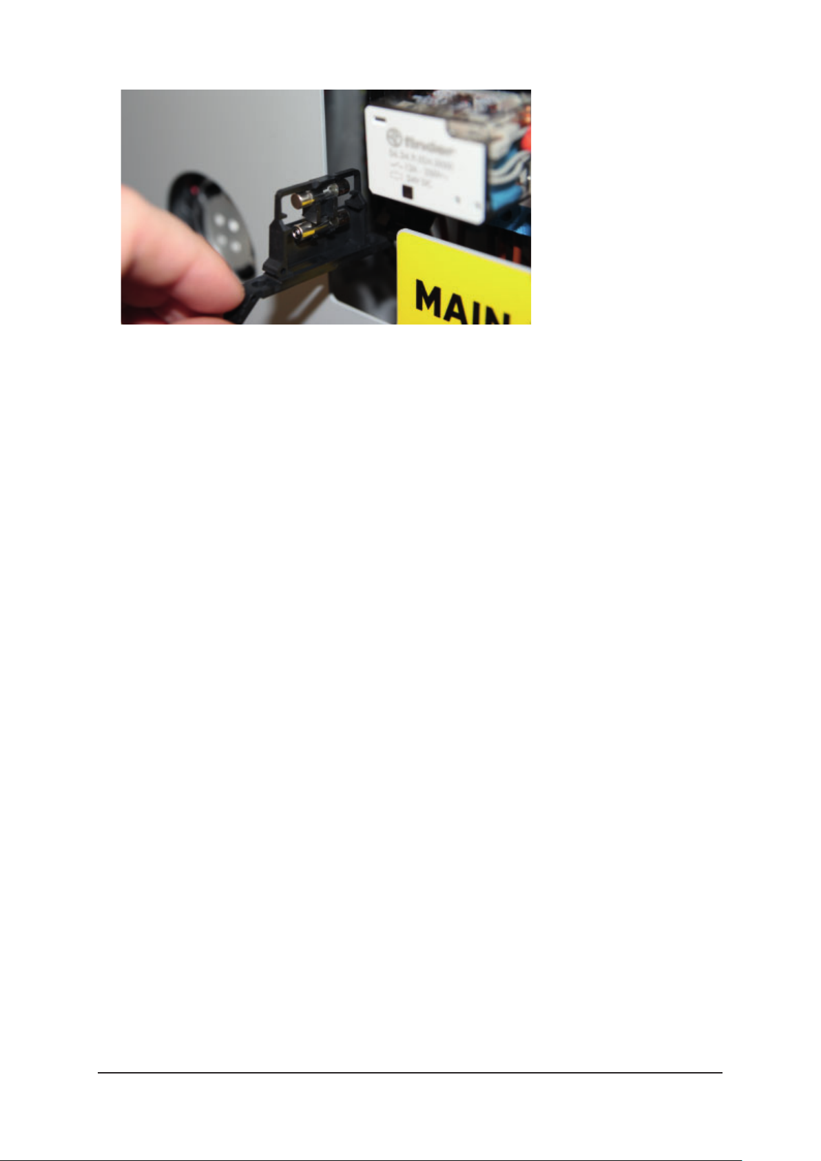
8. Remove the fuse and check it.
9. If it has blown, replace it with a fuse that came with the printer. Place the new
fuse into the slot and place it back into place. Make sure the slot is settled
fi rmly in place.
10. Repeat steps f) to h) until all blown fuses have been replaced.
11. Replace the cover of the printer’s electrical installation area and lock it.
9.8 Resetting the Circuit Breakers
Only replace the fuses if the following has occurred:
1. The printer should be working; however, the light in the printing area is off ,
the fans in the back of the printer are not moving, and the display is dark and
unresponsive.
2. Check the following:
I. The emergency power switch is set to “On”.
II. The switch of the power cable connector in set to “On”.
III. The power cable is connected both to the printer and to a power source.
IV. After checking/amending the steps above, the printer still appears not to be
working.
3. Turn the printer off .
4. Use the key that came with the printer to open the printer’s electrical
installation area.
DEERED — USER MANUAL 35
Page 36
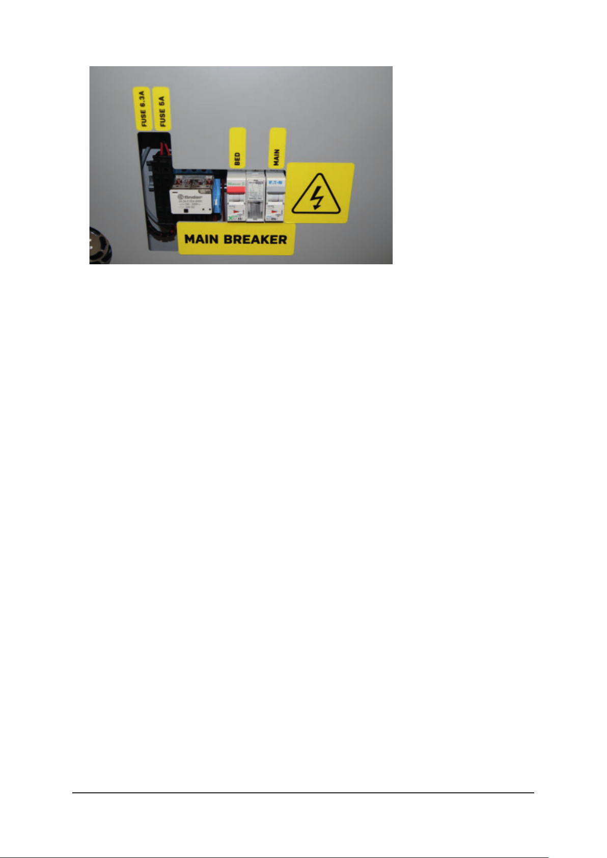
5. Remove the cover of the electrical installation area.
6. Locate the panel with the circuit breakers.
7. Check which circuit breakers have been tripped (the lever of the circuit breaker
will be in the lower position).
8. Reset the tripped circuit breakers (the lever of the circuit breaker should now be
in the upper position).
9. When all circuit breakers have been reset, replace the cover of the printer’s
electrical installation area and lock it.
10. If you turn the printer on and the fuses blow again, contact an authorized
service technician.
9.9 Connecting Peripherals
Camera
1. Turn the printer off .
2. Unpack the camera.
3. Place the camera on the holder in the upper front right corner of the printing
area and secure it using two M4x8 screws.
4. Connect the enclosed cable to the camera.
5. Insert the other end of the cable into the corresponding opening in the wall of
the printer and push the entire length of the cable outside the printing area.
6. Attach the cable to the printer using the USB connector in the printer’s electrical
installation area.
DEERED — USER MANUAL 36
Page 37

9.10 Periodic proactive maintenance
DeeRed requires periodic proactive maintenance which should be performed by
authorized technicians. This maintenance must be done every 6 months after
the initial maintenance, which must be done 2 months after the installation. This
maintenance prevents the potential risk of technical issues.
Periodic proactive maintenance tasks:
• Checking and calibration of mechanical parts
• Maintenance and lubrication of mechanical parts
• Cleaning and calibration of print head
• Replacing of nozzle and tube
• Replacing of drive gear
• Replacing the tubing
• Checking all electrical circuits that are under mechanical stress
• Firmware update
10. TROUBLESHOOTING
10.1 What to Do If the Printer Runs Out of Filament While Printing and Stops
1. If one or both extruders run out of fi lament during the printing process, DeeRed
will pause the process and display a notifi cation. The message will say which
extruder needs its fi lament replaced (see chapter 7.4, “Working with the Printer
Touchscreen – Replacing the Filament”, page 19).
2. Press “Filament Change” to activate the fi lament replacement tool.
3. Press “Remove” and select the extruder that has run out of fi lament.
4. Press “80 mm” and wait until the rest of the fi lament is pushed out of the
extruder.
5. Pull out the free end of the fi lament in the fi lament storage area.
6. Press “Back” on the display and then select “Feed In”.
7. Insert the new fi lament (it must be the same type as the one that has run out).
Then, using the “15 mm”, “30 mm” and “80 mm” buttons, let the fi lament fl ow
through the nozzle into the waste chute. Gently push the fi lament towards the
fi lament entry point for as long as it is fed into the printer head.
8. Make sure the door of the printing chamber is closed.
9. Press “Back” to return to the screen displaying the notifi cation.
10. Press “Continue” to renew the printing process.
DEERED — USER MANUAL 37
Page 38

10.2 Removing Supports
Removing the supports from a model printed on a 3D printer is defi nitely one of the
least interesting tasks that need to be done after printing. Supports are needed for
printing overhangs and bridges – as this particular print technology does not allow
printing onto open space, any parts of the model not directly connected to the print
bed must be supported. Supports can be divided into two groups based on the way
they can be removed – they are either soluble or insoluble.
10.2.1 Insoluble Supports:
Supports that have been printed using the same type of material as the model
itself must be removed manually. This can be done with the help of the enclosed
accessories, but requires some skill. Follow these instructions:
1. Use your hands, a pair of snipping pliers, or other suitable tools to remove as
many supports as you can without damaging the model.
2. Then, use a small knife, scalpel or chisel to remove the smaller supports left over
from the fi rst step.
3. Finally, use a fi le or sandpaper to completely remove the last remnants of the
supports.
10.2.2 Soluble Supports:
The main advantage of soluble supports is that they do not have to be removed
manually. To remove soluble supports, follow these instructions:
1. Use your hands, a pair of snipping pliers, or other suitable tools to remove as
many supports as you can without damaging the model.
2. Immerse the model and the rest of the supports in the dissolving agent.
I. If your model has been printed using PVA, place it into a warm water bath*
(40 °C maximum) and, based on the number of the remaining supports, leave
it there for two to fi ve hours. After this time has passed, remove the model
from the water bath. The remaining supports will be softened; wash them off
under a stream of warm water (40 °C maximum). Use a shower head, a hose,
or a high-pressure water gun for rinsing.
II. If the supports have been printed using HIPS, use “limonene/lemonade”, the
acidic solvent recommended by the supplier, to dissolve them. Immerse the
model in the solvent and, based on the number of the remaining supports,
leave it immersed for two hours or more. You can speed up the dissolving
process signifi cantly by ensuring that there is circulation in the bath (stirring,
a pump, a wave generator, etc.).
3. Rinse the model thoroughly in warm water.
*A water bath that includes dissolved PVA can be tipped down the drain.
DEERED — USER MANUAL 38
Page 39

11. SUPPORT
11.1 Ordering Consumable Materials (Contact and Instructions)
Contact your supplier or local distributor. If, for any reason, that is not possible,
please contact us directly at www.be3dprinters.com.
11.2 Ordering Consumable Components (Contact and Instructions)
Contact your supplier or local distributor. If, for any reason, that is not possible,
please contact us directly at www.be3dprinters.com.
11.3 Support and Maintenance in Case You Need Help (Contact and Instructions)
Contact your supplier or local distributor. If, for any reason, that is not possible,
please contact us directly at www.be3dprinters.com.
12. WARRANTY TERMS AND CONDITIONS
12.1 The Directive on Liability for Defective Products
This Directive is in accordance with the most recent Czech laws addressing the
liability for defective products. It does not guarantee quality.
The mechanical components of the printer are under warranty for a period of
12months after purchase, with the warranty covering any unintentional mechanical
malfunction or defect caused by the manufacturing process or defi ciencies
discovered during assembly. The warranty does not cover incorrect or inappropriate
use, incorrect manipulation, or use and installation that are against the instructions
set forth in this User Manual.
12.2 Terms and Conditions
■ The manufacturer is responsible for the complete functioning of the supplied
software and device in accordance with this User Manual.
■ Any and all malfunctions or defects that have occurred during the manufacturing
or assembly process are covered by the manufacturer in accordance with the
warranty.
■ If a defi ciency within the obligations of the manufacturer occurs, the legitimate
owner is entitled to a repair, free of charge. The defi ciencies will be amended
within 30 days of being reported.
DEERED — USER MANUAL 39
Page 40

12.3 Not Covered by the Warranty
The warranty does not cover malfunctions or defects caused by:
■ Using a non-recommended fi lament;
■ Installation that is in contradiction to the instructions in this User Manual,
eff ective laws, and directives;
■ Using the printer in an unsuitable environment;
■ Improper use;
■ Mechanical usage and wearing out over time.
12.4 User Obligations
The user is obliged to settle the costs and expenses of the technician if a
malfunction was not reported accurately or if they require:
■ The printer to be repaired due to a malfunction caused by the user;
■ The printer to be repaired due to unauthorized changes carried out by the user;
■ The printer to be cleaned and checked;
■ The printer to be repaired due to a power failure.
12.5 Cases in Which the Warranty is Forfeited
■ The user has altered the confi guration of the printer.
■ Instructions set forth in the User Manual were not followed.
■ Filaments not recommended by the manufacturer were used.
■ The user has altered the electronics of the printer.
■ The user/owner has a fi nancial commitment towards the manufacturer or
supplier.
■ The printer was damaged by improper use or shifting during transport or by
being placed in an environment with unsuitable conditions, especially unsuitable
temperature and humidity.
■ The electronics and control units of the printer have been damaged due to
atmospheric events such as storms, power supply fl uctuations, mechanical,
chemical or thermal contamination or damage, or repairs or adjustments carried
out by the user or by an unauthorized service center.
DEERED — USER MANUAL 40
Page 41

13. CONTACT US
Manufacturer:
BE3D, S.R.O.
ID No.: 49356593
VAT No.: CZ49356593
Contact address:
Pod Hájkem 406/1a,
Praha 8, 180 00
Czech Republic
Billing address:
Pod Hájkem 406/1a,
Praha 8, 180 00
Czech Republic
Email: [email protected]
Website: www.be3dprinters.com
be3D reserves the right for any misprints and/or changes
DEERED — USER MANUAL 41
Page 42

TECHNICAL NOTES
Page 43

Page 44

 Loading...