

Page 1
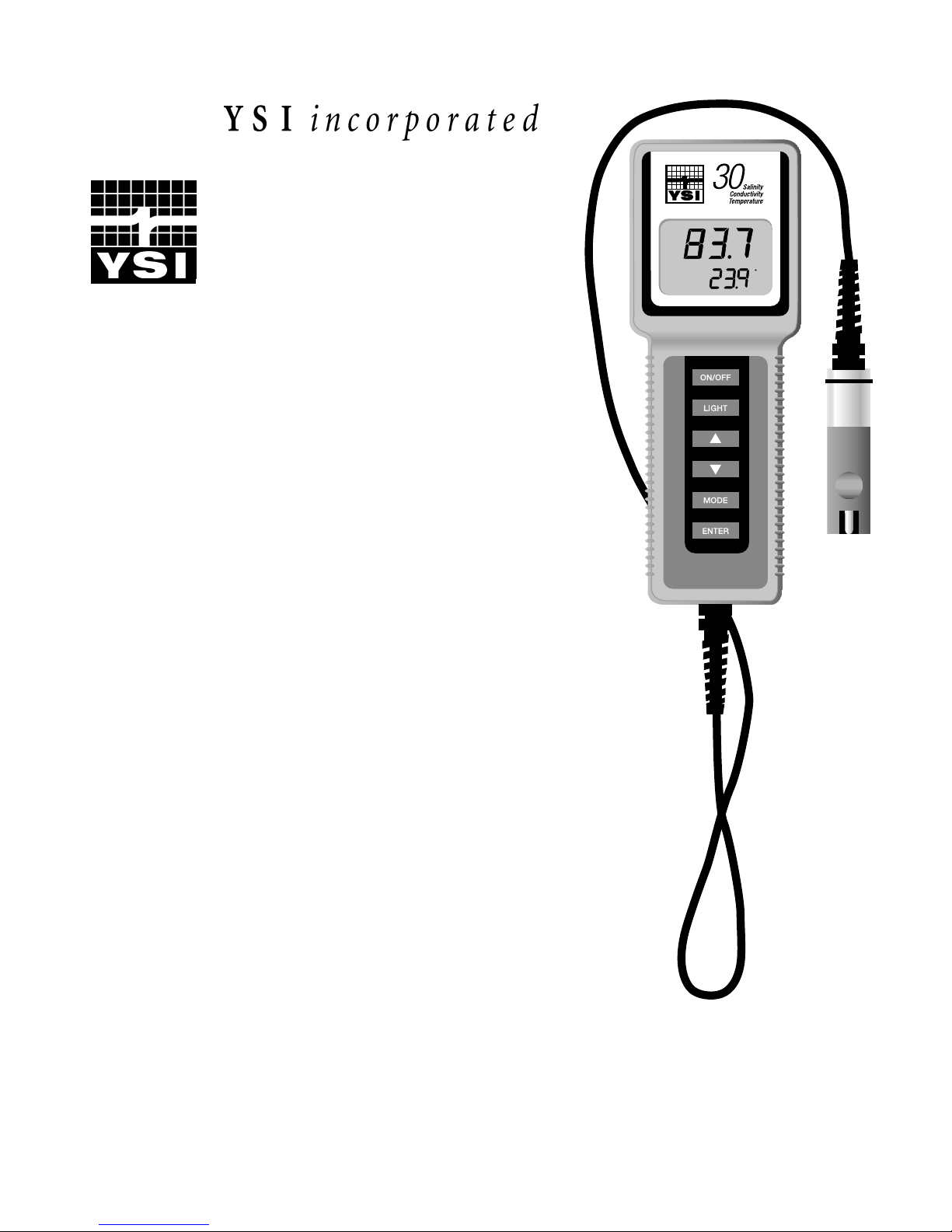
YSI Model 30
YSI Model 30M
µS
C
Handheld Salinity,
Conductivity and
Temperature
System
Operations
Manual
Page 2

Page 3

CONTENTS
Section 1 Introduction..................................................................................................................................................1
Section 2 Preparing The Meter....................................................................................................................................3
2.1 Unpacking..................................................................................................................................................................3
2.2 Warranty Card............................................................................................................................................................3
2.3 Batteries .....................................................................................................................................................................3
2.4 Storage Chamber........................................................................................................................................................4
2.5 Hand Strap .................................................................................................................................................................4
2.6 The Meter Case..........................................................................................................................................................4
Section 3 Making Measurements.................................................................................................................................5
3.1 Turning The Instrum en t On........................................................................................................................................5
3.2 Measurement Modes...................................................................................................................................................6
3.3 Autoranging & R an g e Search in g................................................................................................................................7
3.4 The Backlight..............................................................................................................................................................8
Section 4 Saving Data....................................................................................................................................................9
4.1 Saving Data To Memory...................................................................................................... .......................................9
4.2 Recalling Stored Data.................................................................................................................................................10
4.3 Erasing Stored Data....................................................................................................................................................10
Section 5 Calibration.....................................................................................................................................................13
51 Before You Calibrate...................................................................................................................................................13
5.2 The Calibration Process..............................................................................................................................................13
Section 6 Advanced Setup.............................................................................................................................................15
6.1 Changing The Temperatu re Coef f i cien t.....................................................................................................................15
6.2 Changing The Ref eren ce Temperature.......................................................................................................................16
6.3 Changing From Autoranging To Manu al R an g in g.....................................................................................................17
Section 7 Principles of Operation.................................................................................................................................21
7.1 Temperature Effect.....................................................................................................................................................21
7.2 Discussion Of Measu rement Errors............................................................................................................................22
Section 8 Maintenance...................................................................................................................................................23
8.1 Cleaning And Storag e.................................................................................................................................................25
8.2 Probe Precautions .......................................................................................................................................................25
Section 9 Troubleshooting............................................................................................................................................27
Section 10 Warranty And Repair .................................................................................................................................29
Appendix A Required Notice.....................................................................................................................................35
Appendix B Accessories And Replacement Parts...................................................................................................35
Appendix C Temperature Correction Data..............................................................................................................39
Appendix D Conversion Chart....................................................................................................................................43
Appendix E Glossary...................................................................................................................................................45
Appendix F General Specifications............................................................................................................................47
i
Page 4

ii
Page 5

SECTION 1 INTRODUCTION
The YSI Model 30 Handheld Salinity, Conductivity, & Temperature Sy stem is a rug g ed, microprocessor based, digital meter with an attached YSI four electrode conductivity cell. The Model 30
is designed for use in field, lab, and process control applications and is available with cable lengths
of either 10, 25 or 50 feet. The body of the probe has been manufactured with stainless steel to add
rugged durability and sinking we ig ht. The la rg e Liquid Crystal Display (LCD) is easy to read and is
equipped with a back-light for use in dark or poorly lighted areas.
The Model 30's micro-processor allows the system to be easily ca librate d with the pre ss of a few
keys. Additionally , the micro-processor performs a self-diag nostic routine each time the instrument
is turned on. The self-diagnostic routine provides you with useful information about the cell
constant, function of the instrument circuitry , and the quality of the readings you obtain. For a list of
these diagnostic features, see Section 9, Tr
oubleshooting
The system simultaneously displays te mpera ture (in oC), along with one of the following
parameters: conductivity; temperature compensated conductivity ; (in µS/cm or mS/cm), and salinity
(in parts per thousand [ppt]). Though calibration is
the instrument, regardless of which parameter you wish to read. You can switch back and forth
from salinity, conductivity , and temperature compensated conductivity with a single push of the
MODE
key.
A probe storage chamber is built into the instrument. This chamber provides a convenient place to
store the probe when the system is not in use, and provides protection for the electrodes within the
probe.
.
required, a single calibration will adjust
NOT
The instrument is powered by six AA-size alkaline batteries. A new set of alkaline batteries will
provide approximately 100 hours of continuous operation. When batteries need to be replaced, the
LCD will display a
"LO BAT"
message.
The YSI Model 30 instrument case is waterproof (rated to IP65). You can operate your Model 30 in
a steady rain without damage to the instrument.
The YSI Model 30M contains all the features of the Model 30, but also has internal memory for
saving 50 sets of data for later on screen recall and meets CE requirements for EMC Directive
89/336/EEC. For simplicity, this manual will refer to the Model 30 when discussing functions that
apply to both the Model 30 AND the Model 30M. References to the Model 30M indicate functions
that apply to the Model 30M ONLY.
YSI, Incorporated Model 30/30M 1
Page 6

Introduction Section 1
YSI, Incorporated Model 30/30M 2
Page 7
SECTION 2 PREPARING THE METER
2.1 UNPACKING
When you unpack your new YSI Model 30 Handheld Conductivity, Salinity & Temperature System
for the first time, check the packing list to make sure you have received everything you should have.
If there is anything missing or damag ed, call the dealer from whom you purchased the Model 30. If
you do not know which of our authorized dealers sold the system to you, call YSI Customer Service
at 800-765-4974 or 937-767-7241, and we'll be happy to help you.
2.2 WARRANTY CARD
Before you do anything else, please complete the Warranty Card and return it to YSI . This will
record your purchase of this quality instrument in our computer system. Once your purchase is
recorded, you will receive prompt, efficient service in the event any part of your YSI Model 30
should ever need repair.
2.3 BATTERIES
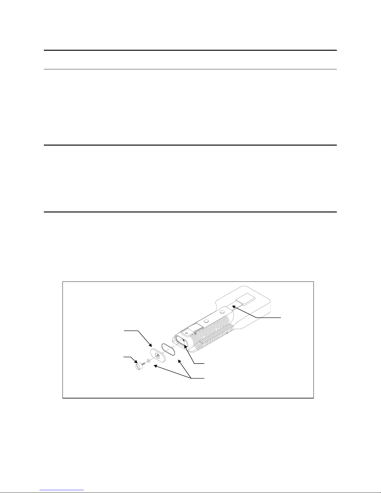
There are a few things you must do to prepare y our YSI Model 30 for use. First, locate the six AAsize alkaline batteries that were included. Use a screwdriver or a small coin to remove the
thumbscrew on the bottom of the instrument. This thumbscrew holds the battery-chamber cover in
place. The battery-chamber cover is marked with the words "OPEN" and "CLOSE."
NOTE: On some models, the battery cover thumbscrew may be unscrewed by hand (a screwdriver
may not be required).
Hand strap
Battery chamber
cover
Thumb screw
Polarity marking
O-rings
There is a small label inside each of the two battery-chamber sleeves. These labels illustrate the
correct way to install the batteries into each sleeve of the battery-chamber.
YSI, Incorporated Model 30/30M 3
Page 8
Preparing the Meter Section 2
NOTE:
It is very important that the batteries be installed ONLY as illustrated. The instrument
will not function if the batteries are installed incorrectly.
Turn the instrument on by pressing and releasing the
ON/OFF
key on the front of the instrument.
The liquid crystal display (LCD) should come on. Allow a few seconds for the instrument to
complete its diagnostic routine. Notice tha t the instrument will displa y the specific cell consta nt of
the probe at the completion of its diagnostic routine. If the instrument does not operate, consult
Section 9,
Troubleshooting
.
You may also want to take the instrument into a dark room and, with the instrument ON, hold down
the
LIGHT
key. The instrument back-light should illuminate the L CD so that the display can be
easily read.
2.4 STORAGE CHAMBER
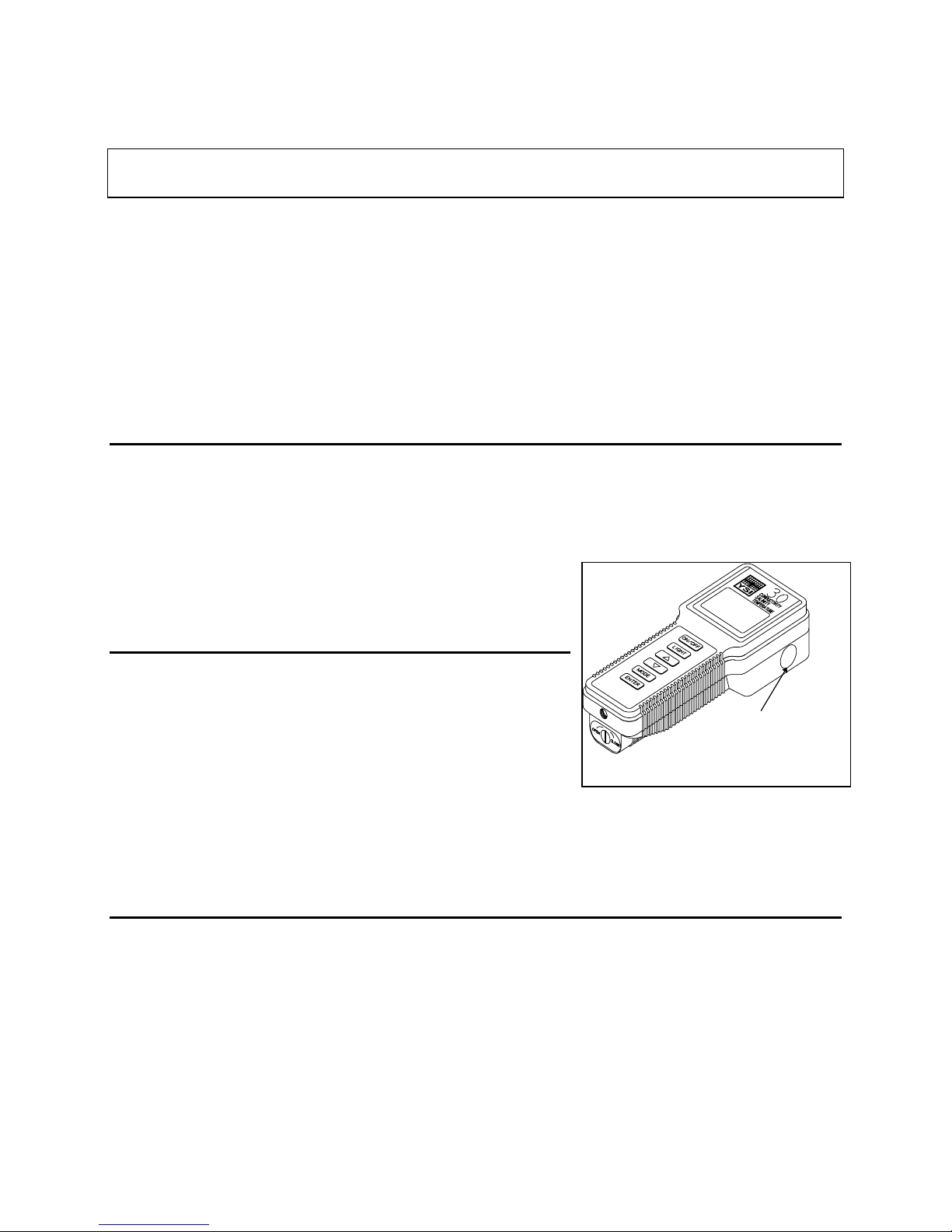
The Model 30 has a convenient storage chamber built into the instrument’s side. This chamber
provides an ideal storage area for the probe during transport and extended non-use.
An optional sponge is available from YSI that will fit inside the storage chamber and provide a
moist environment for probe storage should your application or operational procedures require it.
See Appendix B,
Accessories and Replacement Parts
.
2.5 HAND STRAP
The hand strap is designed to allow comfortable operation of
the Model 30 with minimum effort. If the hand strap is
adjusted correctly , it is unlikely that the instrument will be
Storage Chamber
easily dropped or bumped from y our hand.
To adjust the hand strap on the back of the meter, unsnap the
leather cover and pull the two Velcro strips apart. Place your
hand between the meter and the strap and adjust the strap length so that your hand is snugly held in
place. Press the two Velcro strips back together and snap the leather cover back into place.
2.6 THE METER CASE
The meter case is sealed at the factory and is not intended to be opened, except by authorized
service technicians. Do not attempt to separate the two ha lves of the me ter c ase as this may damage
the instrument, break the water-proof seal and may void the manufacturer's warranty .
YSI, Incorporated Model 30/30M 4
Page 9
SECTION 3 MAKING MEASUREMENTS
The YSI Model 30 is factory calibrated. This means that once you have put batteries in the
instrument, you are rea dy to begin taking reading s imme diately.
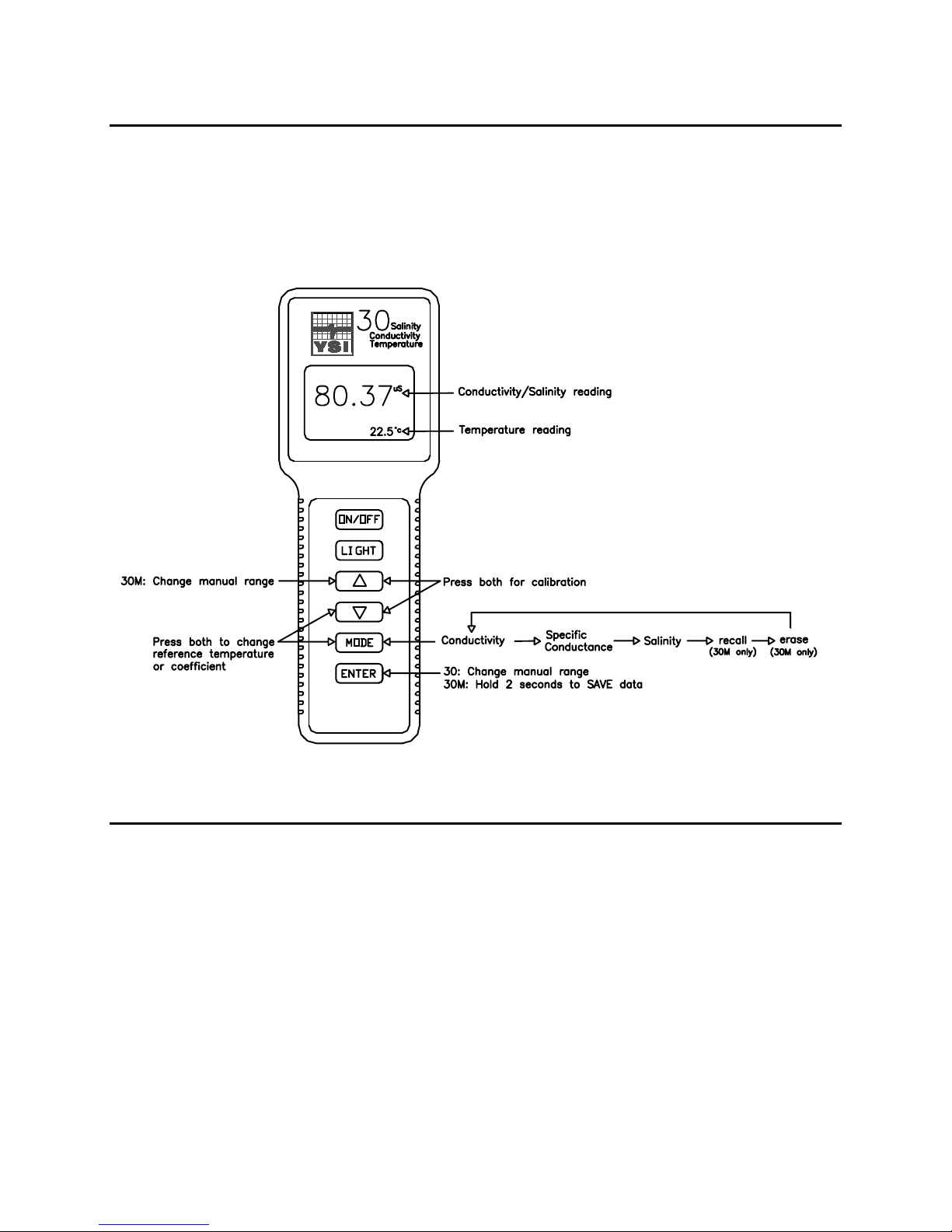
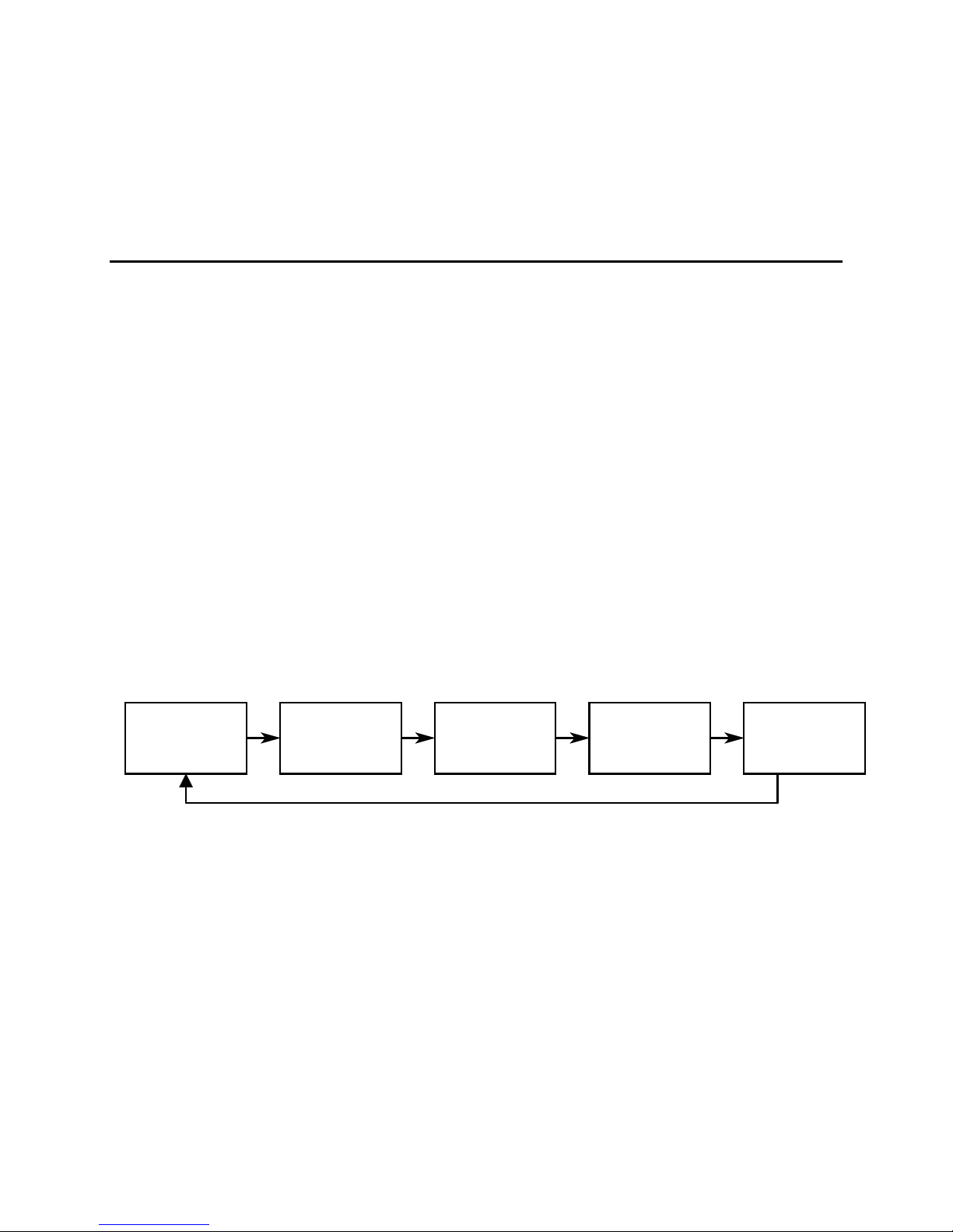
The following diagram is an overview of the operation of the Model 30 and 30M. Note the
difference in key strokes between some of the 30 and 30M functions. See the following pages for
details of operation.
3.1 TURNING THE INSTRUMENT ON
Once the batteries are installed correctly, press the
segments of the display for a few seconds, which will be followed by a self test procedure which
will last for several more seconds. During this power on self test sequence, the instrument’s
microprocessor is verifying that the instrume nt is working properly and will display the c ell
constant of the probe when the self test is complete. If the instrument were to detect a problem, a
continuous
messages.
After the self test procedure is complete, the tempe rature will be displayed in the lower right of the
display and the instrument is rea dy to make a measurement. Simply insert the probe into the liquid
sample about which you would like to receive information. It is important that the probe be inserted
into the liquid deep enough so that the hole on the side of the probe is completely covered by the
liquid. If possible, do not allow the probe to touch any solid object while you are taking readings;
YSI, Incorporated Model 30/30M 5
error message would be displayed. See Section 9,
ON/OFF
key. The instrument will activa te a ll
Troubleshooting
for a list of error
Page 10
Making Measurements Section 3
this may effect the reading slightly. Additionally, it is important that there not be any air bubbles
around the probe electrodes. To dislodge any bubbles which might have formed, move or shake the
probe vigorously severa l times before rec ording the me asurement.
3.2 MEASUREMENT MODES
The Model 30 has three modes as follows:
Conductivity
!
-- A measurement of the conductive material in the liquid sample without regard
to temperature
Specific Conducta nce
!
-- Also known as temperature compensated conductivity which
automatically adjusts the rea ding to a c alc ulate d value which would have bee n rea d if the
sample had been at 25o C (or some other reference temperature which you choose). See Section
6,
Advanced Setup
Salinity
!
-- A calculation done by the instrument electronics, based upon the conductivity and
.
temperature readings.
Temperature
The Model 30M has two additional modes:
Recall
!
Erase all
!
To change between modes, simply press and release the
is displayed in conductivity , specific conductance and salinity modes.
-- Allows previously stored data to be display ed.
-- Allows ALL previously stored data to be deleted.
MODE
key. The instrument will cycle
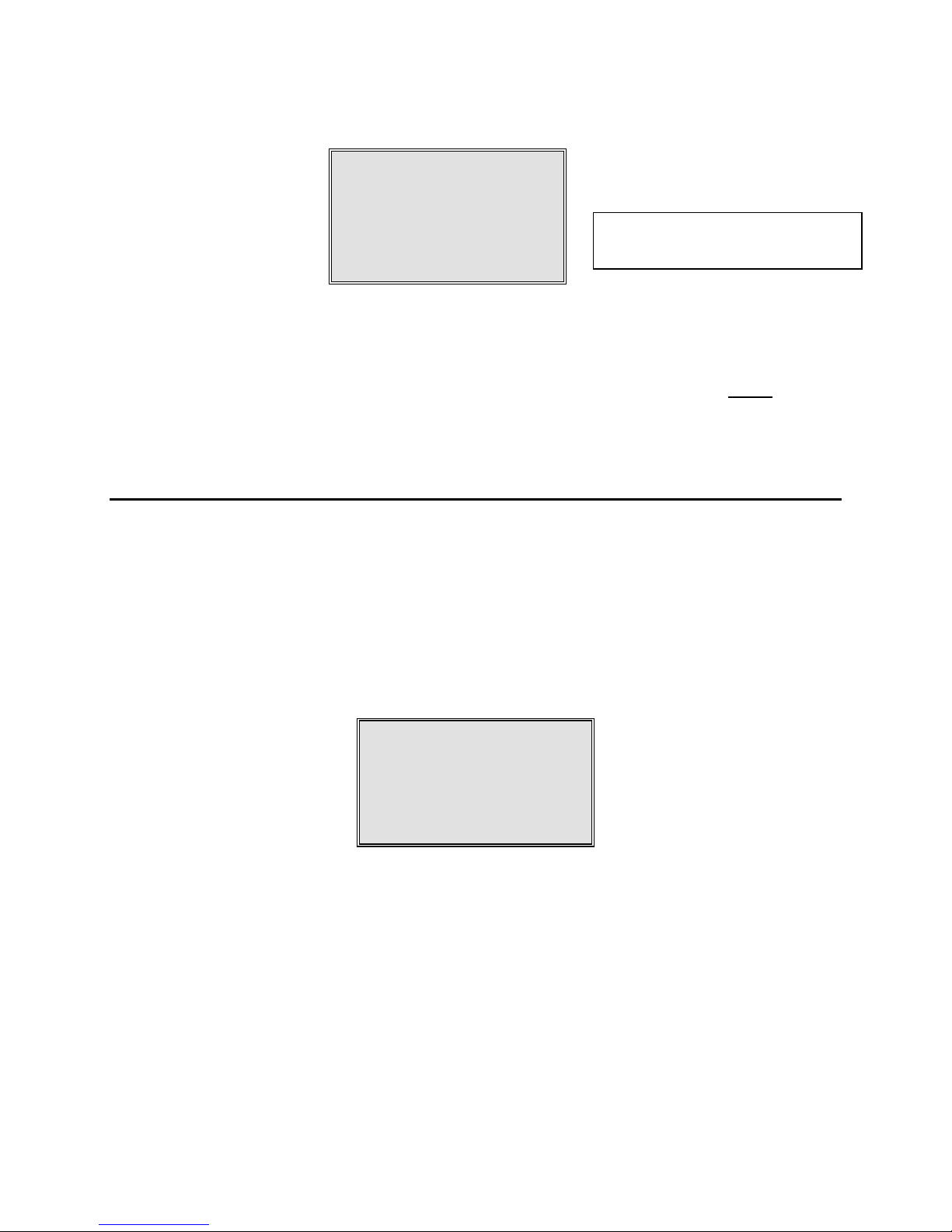
through the modes as follows:
Conductivity
with °C
Specific
Conductance with °C
Salinity
with °C
Recall
(Model 30M ONLY)
(Model 30M ONLY)
Erase all
NOTE:
When you turn the instrument off, it will “re member” which mea sureme nt mode you used
last and will return to that mode the next time it is turned on.
When changing modes, carefully observe the small legends at the far rig ht side of the LCD. If the
instrument is reading
either a
S
µµµµ
or an
Specific Conducta nce ,
Additionally, the small portion of the display will show the
mS.
and off .
YSI, Incorporated Model 30/30M 6
the large numbers on the display will be followed by
o
flashing on
C
Page 11
Making Measurements Section 3
If the instrument is reading
either a
If the instrument is reading
S
µµµµ
or an
Additionally, the small portion of the display will show the
mS.
300.1
Conductivity,
Salinity,
the large numbers on the display will be followed by a
24.8
the large numbers on the display will be followed by
uS
°C
°C Not flashing = Conductivity
°C Flashing = Specific conductance
o
C NOT
flashing.
ppt.
3.3 AUTORANGING & RANGE SEARCHING
The YSI Model 30 is an autoranging instrument. This means that, regardless of the conductivity or
salinity of the solution (within the specific ations of the instrument), all you need to do to get the
most accurate reading is to put the probe in the sample. This feature makes the Model 30 as simple
as possible to operate.
When you first place the Model 30 probe into a sample or calibration solution, and again when y ou
first remove the probe, the instrument will go into a range sea rc h mode that ma y take as long as 5
seconds. During some range searches, the instrument display will flash
movement from one range to another.
rANG
to indicate its
The length of the range search depends on the number of ranges which must be searched in order to
find the correct range for the sample. During the rang e se arc h, the instrume nt will appea r to free ze
on a given reading for a few seconds then, once the range is located, will pinpoint the exact reading
on the display. The display may a lso switch to
it selects the proper range.
During normal operation, the
the autoranging feature of the instrument. We recommend that the instrument always be operated
using the autoranging feature. See Section 6,
ranging.
YSI, Incorporated Model 30/30M 7
ENTER
rANG
for a second or two during a range search before
00.0
key (
UP ARROW
Advanced Setup
key on Model 30M) enables and disables
if you need to switch to manual
Page 12

Making Measurements Section 3
3.4 THE BACKLIGHT
At times it may be necessary to take measurements with the Model 30 in dark or poorly lit areas. To
help in this situation, the Model 30 comes equipped with a backlight which will illuminate the
display so that it can be easily read. To activate the backlig ht, press and hold down the
LIGHT
The display will remain lit as long a s the ke y is held down. When you re lea se it, the lig ht g oes out
to preserve battery life.
key.
YSI, Incorporated Model 30/30M 8
Page 13
SECTION 4 SAVING DATA
y
The Model 30M is equipped with non-volatile memory that is capable of storing up to 50 different
sets of readings. Non-volatile means that you do not need to worry that your data will be lost due to
a power failure or interruption, such as when the batteries are removed. The Model 30M will also
assign a site identity number to each set of readings to allow easy review of the data. This feature is
useful in situations where transcribing data is difficult or not available.
NOTE: The Model 30 is NOT equipped with memory and cannot save data.
4.1 SAVING DATA TO MEMORY
1. While any parameter is displayed on the screen, press the
approximately 2 seconds.
SAVE
01
The meter will flash
2. When all 50 sites are full, the display will flash
on the screen (even after power down) until a key is pushed.
SAVE
on the display along with the curre nt site ide ntity is being used.
FULL
on the screen. This message will remain
FULL
ENTER
key and hold for
Site identit
Once you have acknowledged the memory is full, any subsequent saved data will begin overwriting
existing data starting with site #1.
YSI, Incorporated Model 30/30M 9
Page 14
Saving Data Section 4
4.2 RECALLING STORED DATA
1. To put the Model 30M into the
the screen along with the site I D numbe r in the lower rig ht c orner .
RECALL
mode, press the
MODE
key until
is displayed on
rcl
rcl
2. Press the
the conductivity and temperature. Another press of the
conductance and the temperature. Press the
also displayed with the tempe rature .
3. Press the
4. Press the
NOTE:
30M will display the Site ID# for the previously recorde d data. F or e xample: I f you are reviewing
Site ID# 5 and the
reviewing Site ID# 5 and Site I D# 5 was the last set of data stored, the
display Site ID # 1.
ENTER
UP ARROW
DOWN ARROW
The Model 30M will recall data as a list. When the
key to review the last se t of data that wa s saved. The Model 30M will displa y
ENTER
key to increment through the saved sets of data.
key to decrement through the saved sets of data.
UP ARROW
is pressed, the Model 30M will display Site ID# 4. If you are
01
ENTER
key again to re view the salinity which is
UP ARROW
Site identity
key will display the specific
is pressed the Model
DOWN ARROW
key will
Here is an example of the Model 30M memory.
Site ID #1
Site ID #2
Site ID #3 If the
Site ID #4
Site ID #5
UP ARROW
key was pressed the Model 30M would display Site ID #2
4.3 ERASING STORED DATA
1. To erase the data that is stored into the Model 30M’s memory, press the
Model 30M displays
on the screen.
ErAS
MODE
key until the
ErAS
YSI, Incorporated Model 30/30M 10
Page 15
Saving Data Section 4
2. Press and hold both the
5 seconds.
3. Successful erasure is indicated by the Model 30M flashing
seconds. The instrument will automatically change to normal operation after completion.
DOWN ARROW
and
ENTER
keys simultaneously for approximately
DONE
on the display for 1 to 2
dOnE
IMPORTANT: Data in all 50 site ID’s will be erased completely and will be lost forever. Do
not use the erase function until all recorded data has been transcribed to an
archive outside the Model 30M.
YSI, Incorporated Model 30/30M 11
Page 16

Saving Data Section 4
YSI, Incorporated Model 30/30M 12
Page 17

SECTION 5 CALIBRATION
5.1 BEFORE YOU CALIBRATE
IMPORTANT
YSI Model 30. However, from time to time it is wise to check the system calibration and make
adjustments when necessary.
Before you calibrate the YSI Model 30, complete the procedures discussed in the
the Meter
To accurately calibrate the YSI Model 30, it is important to remember the following :
1.
Always use clean, properly stored, NIST traceable calibrator solutions
Accessories and Replacement Parts
the calibration procedures, make certain that the level of calibrant buffers is high enough in the
container to cover the entire conductivity cell. Gently ag itate the probe to remove any bubbles
in the conductivity cell.
2. Rinse the probe with deionized water (and wipe dry) between changes of calibration solutions.
3. During calibration, allow the probe time to stabilize with regard to temperature (approximately
60 seconds) before proceeding with the calibration process.
only as good as the calibration itself.
4. Perform sensor calibration at a temperature as close to 25°C as possible. This will minimize any
temperature compensation error.
: System calibration is rarely required because of the factory calibration of the
Preparing
and
Making Measurements
sections of this manual
). When filling a calibration container prior to performing
.
(see Appendix B,
The readings after calibration are
5.2 THE CALIBRATION PROCESS
System calibration is rarely required because of the factory calibration of the YSI Model 30.
However, from time to time it is wise to check the system calibration and make adjustments when
necessary.
Follow these steps to perform an accurate calibration of the YSI Model 30:
1. Turn the instrument on and allow it to complete its self test procedure.
2. Select a calibration solution which is most similar to the sample you will be measuring.
For sea water choose a 50 mS/cm conductivity standard (YSI Catalog# 3169).
•
For fresh water choose a 1 mS/cm conductivity standard (YSI Catalog# 3167).
•
For brackish water choose a 10 mS/cm conductivity standard (YSI Catalog # 3168).
•
3. Place at least 3 inches of solution in a clean glass beaker.
4. Insert the probe into the beaker deep enough to completely cover the oval shaped hole on the
side of the probe. Do not rest the probe on the bottom of the container -- suspend it above the
bottom at least 1/4 inch.
YSI, Incorporated Model 30/30M 13
Page 18
Calibration Section 5
5. Press the
6. Allow at least 60 seconds for the temperature reading to become stable.
7. Move the probe vigorously from side to side to dislodge any air bubbles from the electrodes.
8. Press and release both the
CAL
in Calibration mode.
9. Use the
matches the value of the calibration solution you are using.
MODE
symbol will appear at the bottom left of the display to indicate that the instrument is now
UP ARROW
key until the instrument is reading conductivity or specific conductance.
UP ARROW
CAL
or
DOWN ARROW
and
DOWN ARROW
µµµµ
µµµµ
S
°C
S
1014
24.8
key to adjust the rea ding on the displa y until it
1000
keys at the same time . The
Cal symbol
Value of calibration
solution at 25°C
24.8
CAL
10. Once the display rea ds the e xact value of the ca libration solution being use d (the instrume nt
will make the appropriate compensation for temperature variation from 25°C), press the
ENTER
calibration has been accepted.
NOTE: If the up or down arrow keys are not pressed during the calibration process, the “SAVE”
key. The word “
message will not be display e d since the c alibration va lue ha s not cha ng ed. If an error
occurs during calibration, see Section 9,
SAVE”
will flash across the display for a second indicating that the
SAVE
Troubleshooting
°C
.
YSI, Incorporated Model 30/30M 14
Page 19

SECTION 6 ADVANCED SETUP
The default settings of the YSI Mode l 30 are appropria te for the vast majority of measurement
applications. However, some measurement applications require very specific measurement criteria.
For that reason, we have made the YSI Model 30 flexible to accommodate these “advanced users.”
If, for example, you are using the YSI Model 30 for a process control application which requires
that the conductivity readings be compensated to 20 oC instead of 25 oC -- this is the section to read.
Or, if your application for the YSI Model 30 involves the measurement of a very specific saline
solution, the default temperature coefficient may need to be changed to get the very best
measurement of that specific salt.
IMPORTANT:
measurement application calls for a change in reference temperature and/or temperature coefficient.
Therefore, unless you are certain that y our application requires a chang e to one or both of these
criteria, do not modify the default reference temperature (25oC) or the default temperature
coefficient (1.91%).
There is never a need to enter Advanced Setup Mode unless your special
6.1 CHANGING THE TEMPERATURE COEFFICIENT
Follow these steps to modify the temperature coefficient of the Model 30.
1. Turn the instrument on and wait for it to complete its self test procedure.
2. Press and release both the
symbol will appear at the bottom left of the displa y and the large portion of the display will
show
% (or a value set previously using Advanced Setup).
1.91
DOWN ARROW
1.91
CAL
and
22.7
MODE
%
keys at the same time . The
Temperature coefficient
°C
CAL sy mbol
CAL
3. Use the
temperature coefficient.
YSI, Incorporated Model 30/30M 15
UP ARROW
or
DOWN ARROW
1.50
CAL
key to change the value to the desired new
New temperature coeffi cient
22.7
%
°C
Page 20
Advanced Setup Section 6
4. Press the
that your change has been accepted.
5. Press the
display.
See
Appendix C
ENTER
MODE
key. The word “
key to return to normal operation; the
for charts of common salt solutions at various temperatures.
SAVE
” will flash across the display for a second to indicate
symbol will disappear from the
CAL
6.2 CHANGING THE REFERENCE TEMPERATURE
Follow these steps to modify the reference temperature of the Model 30.
1. Turn the instrument on and wait for it to complete its self test procedure.
2. Press and release both the
DOWN ARROW
and
MODE
keys at the same time .
%
1.91
°C
CAL sy mbol
CAL
22.7
The
3. Press and release the
symbol will appear at the bottom le ft of the displa y and the large portion of the display
CAL
will show
set previously using Advanced Setup).
% (or a value set previously using Advanced Setup).
1.91
MODE
key; the large portion of the display will show
25.0C
22.7
CAL
Reference temperature
25.0C
(or a value
YSI, Incorporated Model 30/30M 16
Page 21

Advanced Setup Section 6
4. Use the
reference temperature (any value between 15 oC and 25 oC is acceptable).
5. Press the
that your change has been accepted. The instrument will automatically return to normal
operation mode.
UP ARROW
ENTER
or
DOWN ARROW
key. The word “
key to change the value to the desired new
15.0C
22.7
CAL
SAVE
” will flash across the display for a second to indicate
New reference temperatu re
6.3 CHANGING FROM AUTORANGING TO MANUAL RANGING
If your application is easier to perform using a manual rang e which you select, the YSI Model 30
and Model 30M allow you to turn off the default autoranging feature. Follow the instructions for
your model as shown below.
Model 30
While you are making conductivity or specific conductance measurements with the Model 30,
simply press and release the
Each additional press of the
you return again to autoranging . Five pushes of the
the four manual ranges and return the instrument to autoranging.
NOTE:
adequate for the sample you are measuring.
You may see an error message in some manual ranges if the manual rang e selected is not
ENTER
ENTER
key to select manual ranging.
S
1014
24.8
CAL
key will cycle the Model 30 to a different manual rang e until
µµµµ
ENTER
°C
key will cycle the Model 30 through
YSI, Incorporated Model 30/30M 17
Page 22
Advanced Setup Section 6
rErr
24.8
If this happens, simply press and release the
for your sample. If you get lost and don’t know if y ou’re in a manual rang e or autorang ing , simply
turn the instrument off and back on. The instrument will always default to autoranging when first
turned on.
Model 30M
While you are making conductivity or specific conductance measurements with the Model 30M,
simply press and release the
units will flash on the Model 30M to indicate that the instrument is in a manual ra ng e.
UP ARROW
ENTER
key to select manual ranging. Note that the conductivity
1014
24.8
CAL
mS
°C
key until a range is sele cte d which is suita ble
S
µµµµ
°C
Range error
message
30M ONLY: Flashing
units indicate manual
range
Each additional press of the
range until you return ag a in to autorang ing . F ive pushe s of the
Model 30M through the four manual ranges and return the instrument to autoranging.
NOTE:
YSI, Incorporated Model 30/30M 18
You may see an error message in some manual ranges if the manual rang e selected is not
adequate for the sample you are measuring.
UP ARROW
key will cycle the Model 30M to a different manual
key will cycle the
rErr
mS
24.8
UP ARROW
Range error
message
°C
Page 23
Advanced Setup Section 6
If this happens, simply press and release the
UP ARROW
key until a range is sele cted which is
suitable for your sample. Note that the instrument will a lways default to autoranging whe n first
turned on.
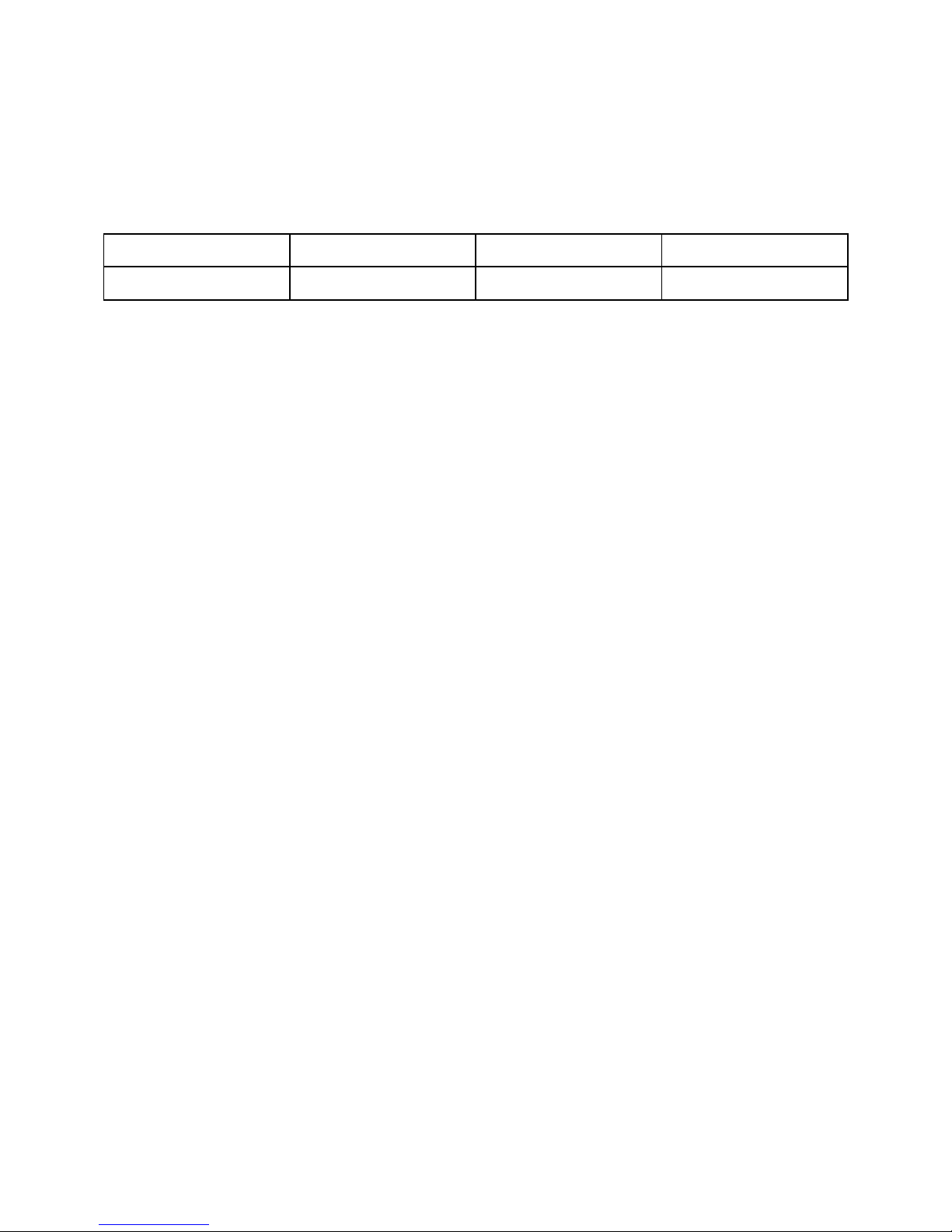
The four ranges of the YSI Model 30 are:
Range 1 Range 2 Range 3 Range 4
0 to 499.9 µS/cm 0 to 4999 µS/cm
0 to 49.99 mS/cm 0 to 200.0 mS/cm
YSI, Incorporated Model 30/30M 19
Page 24

Advanced Setup Section 6
YSI, Incorporated Model 30/30M 20
Page 25

SECTION 7 PRINCIPLES OF OPERATION
The Model 30 utilizes a cell with four pure nickel electrodes for the me asure ment of solution
conductance. Two of the electrodes are current driven and two are used to measure the voltage
drop. The measured voltage drop is then converted into a conductance value in milliSiemens
(millimhos). To convert this value to a conductivity value in milliSiemens per cm (mS/cm), the
conductance is multiplied by the cell constant which has units of reciprocal cm (cm-1). The cell
constant for the Model 30 conductivity cell is 5.0/cm ±4%. For most applications, the cell constant
is automatically determined (or confirmed) with each deployment of the system when the
calibration procedure is followed; see section 6.2. Solutions with conductivities of 1.00, 10.0, 50.0,
and 100.0 mS/cm, which have been prepared in accordance with recommendation 56-1981 of the
Organisation Internationale de Métrologie L é ga le (OIML), are available from YSI. The instrument
output is in µS/cm or mS/cm for both conductivity and specific conductance. The multiplication of
cell constant times conductance is carried out automatically by the software.
7.1 TEMPERATURE EFFECT
The conductivity of solutions of ionic species is highly dependent on temperature, varying as much
as 3% for each change of one degree Celsius (temperature coefficient = 3%/°C). In addition, the
temperature coefficient itself varies with the nature of the ionic species present. Because the exact
composition of a natural media is usually not known, it is best to report a conductivity at a
particular temperature, e.g. 20.2 mS/cm at 14°C. However, in many cases, it is also useful to
compensate for the temperature dependence in order to determine at a glance if gross changes are
occurring in the ionic content of the medium over time. For this reason, the Model 30 software also
allows the user to output conductivity data in either raw or temperature compensated form. If
"Conductivity" is selected, values of conductivity which are
output to the display. If " Specific Conductance" is selected, the Model 30 uses the temperature and
raw conductivity values associated with each determination to generate a specific conductance
value compensated to a user selected reference temperature (see section 6,
between 15°C and 25°C. Additionally the user can select any temperature coefficient from 0% to
4% (see Section 6,
Advanced Setup).
Using the Model 30 default reference tempera ture and
temperature coefficient (25°C and 1.91%), the calculation is carried out as in equation (1) below:
compensated for temperature are
NOT
Advanced Setup
)
Specific Conductance (25°C) = Conductivity
1 + TC * (T - 25)
As noted above, unless the solution being measured consists of pure KCl in water, this temperature
compensated value will be somewhat inaccurate, but the equation with a value of TC = 0.0191 will
provide a close approximation for solutions of many common salts such as NaCl and NH
for seawater.
YSI, Incorporated Model 30/30M 21
Cl and
4
Page 26

Principles of Operation Section 7
Salinity is determined automatically from the Model 30 conductivity readings according to
algorithms found in
Standard Methods for the Examination of Water and Wastewater ( ed. 1995).
The use of the Practical Salinity Scale 1978 results in values which are unitless, since the
measurements are carried out in reference to the conductivity of standard seawater at 15°C.
However, the unitless salinity va lues ar e ve ry close to those determined by the previously-used
method where the mass of dissolved salts in a given mass of water (parts per thousand) was
reported. Hence, the designation "ppt" is reported by the instrument to provide a more conventional
output.
For further information on conductivity and the above standard information, refer to the ASTM
document,
Wastewater
Standard Methods of Test for Electrical Conductivity of Water and Industrial
, ASTM Designation D1125-82, and OIML
Recommendation Number 56
. ASTM
symbols for conductivity , cell constant, and path leng th differ from those preferred in the g eneral
literature and also from those used in this manual.
7.2 DISCUSSION OF MEASUREMENT ERRORS
System accuracy for conductivity measurements is equal to the sum of the errors contributed by the
environment and the various components of the measurement setup. These include:
Instrument accuracy
⋅
Cell-constant error
⋅
Solution temperature offset
⋅
Cell contamination (including air bubbles)
⋅
Electrical noise
⋅
Galvanic effects
⋅
Only the first three are of major concern for ty pical measurements, althoug h the user should also be
careful to see that cells are clean and maintained in good condition at all times.
Instrument Accuracy = ± .5% maximum
The accuracy specified for the range being used is the worst case instrument error.
Cell-Constant Error = ± .5% maximum
Although YSI cells are warranted to be accurate to within one percent, y ou should still determine
the exact cell constant of your particular cell. Contamination or physical damag e to the cell can alter
the cell constant. Performing a calibration will eliminate any error which might arise because of cell
constant change.
YSI cells are calibrated to within one percent of the stated cell constant at a single point. We
consider these products to be usefully linear over most instrument ranges. The cell constant can be
calibrated to ±0.35% accuracy with YSI conductivity calibrator solutions.
Temperature Error = ± 1% maximum
The solution temperature error is the product of the temperature coefficient and the temperature
offset from 25°C, expressed as a percentage of the reading that would have been obtained at 25°C.
YSI, Incorporated Model 30/30M 22
Page 27

Principles of Operation Section 7
The error is not necessarily a linear function of temperature. The statement of error is derived from
a 25°C temperature offset and a 3%/°C temperature coefficient.
Total Error
Considering only the above three factors, system accuracy under worst case conditions will be ±2%,
although the actual error will be considerably less if recommended and properly calibrated cells and
instrument ranges are used. Additional errors, which c an e ssentially be eliminated with proper
handling, are described below.
Cell Contamination
This error is usually due to contamination of the solution being measured, which occurs when
solution is carried-over from the last solution measured. Thus, the instrument might be correctly
reporting the conductivity seen, but the reading does not accurately represent the value of the bulk
solution. Errors will be most serious when low conductivity solutions are contaminated by carryover from high conductivity solutions, and can then be of an order of magnitude or more.
Follow the cleaning instructions carefully before attempting low conductivity measurements with a
cell of unknown history or one that has been previously used in hig her value solutions.
An entirely different form of contamination sometimes occurs due to a buildup of foreign material
directly on cell electrodes. While rare, such deposits have, on occasion, markedly reduced the
effectiveness of the electrodes. The result is an erroneously low conductance reading.
Electrical-Noise Errors
Electrical noise can be a problem in any measurement range, but will contribute the most error a nd
be the most difficult to eliminate when operating in the lowe st rang e s. The noise ma y be either lineconducted or radiated or both, and may require, grounding, shielding , or both.
Galvanic and Miscellaneous Effects
In addition to the error sources described above, there is another class of contributors that can be
ignored for all but the most meticulous of laboratory measurements. These errors are always small
and are generally completely masked by the error budget for cell-constant calibration, instrument
accuracy, etc. Examples range from parasitic reactances associated with the solution container and
its proximity to external objects to the minor galvanic effe cts resulting from oxide formation or
deposition on electrodes. Only trial and error in the actual measurement environment can be
suggested as an approach to reduce such errors. If the reading does not change as the setup is
adjusted, errors due to such factors can be considered too small to see
YSI, Incorporated Model 30/30M 23
Page 28

Principles of Operation Section 7
YSI, Incorporated Model 30/30M 24
Page 29
SECTION 8 MAINTENANCE
8.1 CLEANING AND STORAGE
The single most important requirement for accurate and reproducible results in conductivity
measurement is a clean cell. A dirty cell will change the conductivity of a solution by contaminating
it.
NOTE:
To clean the conductivity cell:
1. Dip the cell in cleaning solution and agita te for two to thre e minute s. Any one of the foaming
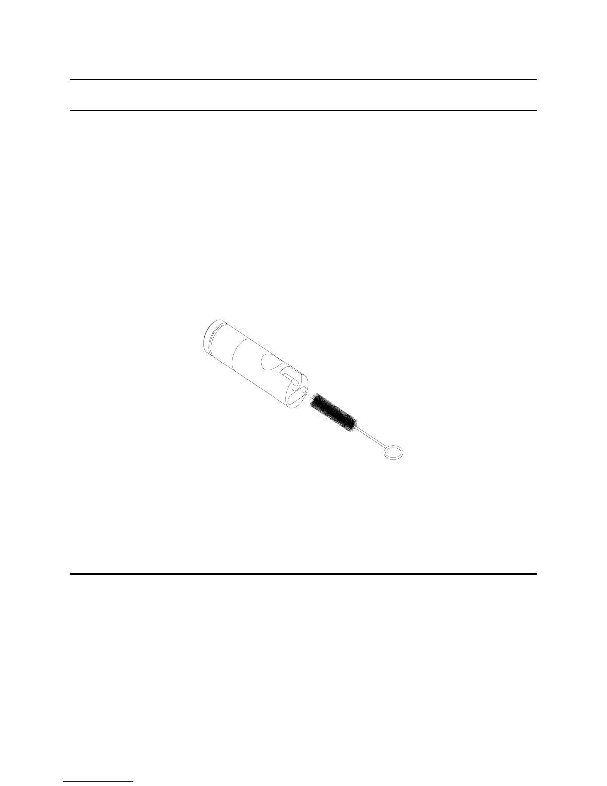
2. Use the nylon brush (supplied) to dislodge any contaminants from inside the electrode chamber.
ALWAYS RINSE THE CONDUCTIVITY CELL WI TH CLEAN WATER AFTER
EACH USE.
acid tile cleaners, such as Dow Chemica l Ba throom Clea ner , will cle an the ce ll ade quately.
When a stronger cleaning preparation is required, use a solution of 1:1 isopropyl alcohol and
10N HCl. Remove the cell from the cleaning solution.
3. Repeat steps one and two until the cell is comple tely clean. Rinse the cell thoroug hly in
deionized, or clean tap water.
4. Store the conductivity cell in the meter storage chamber.
8.2 PROBE PRECAUTIONS
Observe the following precautions to ensure accurate, repeatable results:
1. The cell must be clean before making any measurements. When working with substances
having low conductivity, extraordinary cleanliness may be required.
2. Suspend the cell in the solution deep enough to submerge the vent hole. The electrode chamber
should be free of trapped air. You may need to tap the probe gently to dislodge any air bubbles.
3. Ideally, the cell should be at least ¼ inch away from any other object, including the sides or
bottom of the solution container.
YSI, Incorporated Model 30/30M 25
Page 30

Maintainence Section 8
4. Stirring may be necessary for hig hest accuracy measurements, especially in low-conductivity
solutions.
5. If possible, isolate from ground potential the container or system in which measurements are to
be made.
6. Electrical fields and stray currents caused by stirrer motors, heaters, etc., can interfere with
measurements. The user should determine the effects of these and make the necessary
corrections, either by shielding or by disconnecting those units that cause trouble.
7. Always rinse the cell carefully before transferring it from one solution to another.
8. Never store a dirty or contaminated cell.
YSI, Incorporated Model 30/30M 26
Page 31
SECTION 9 TROUBLESHOOTING
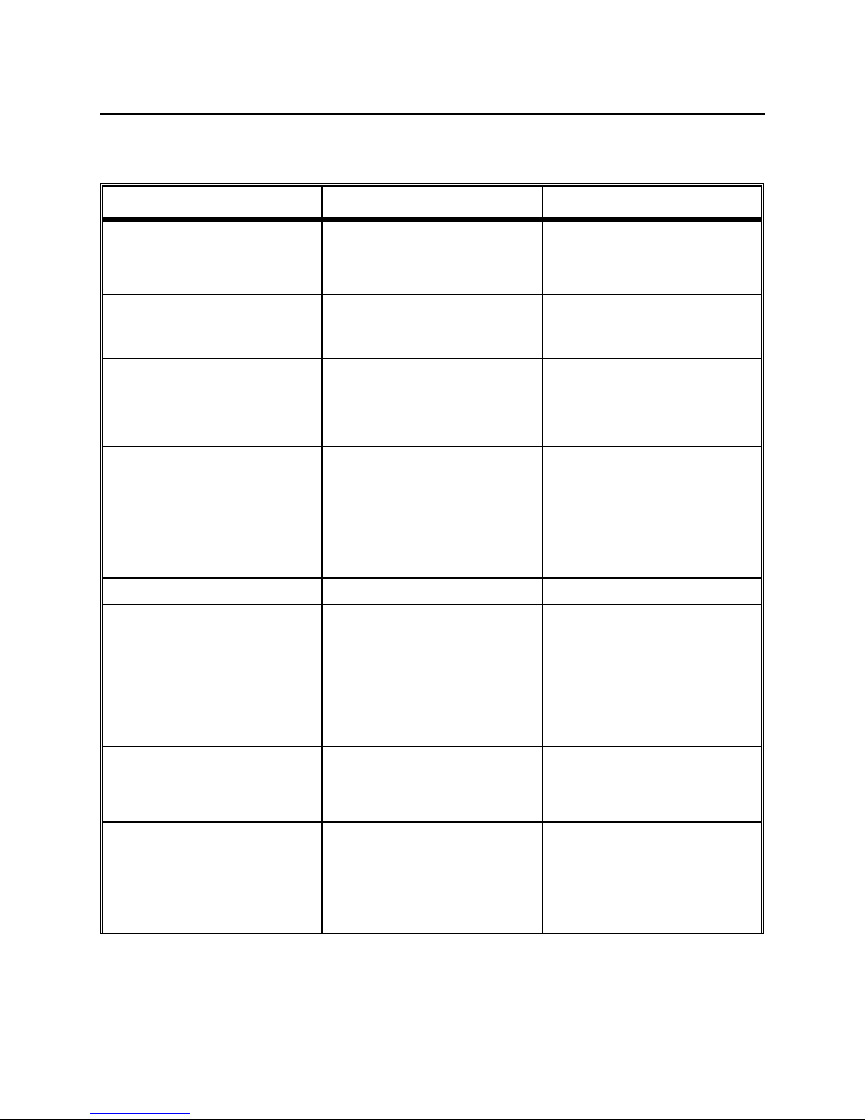
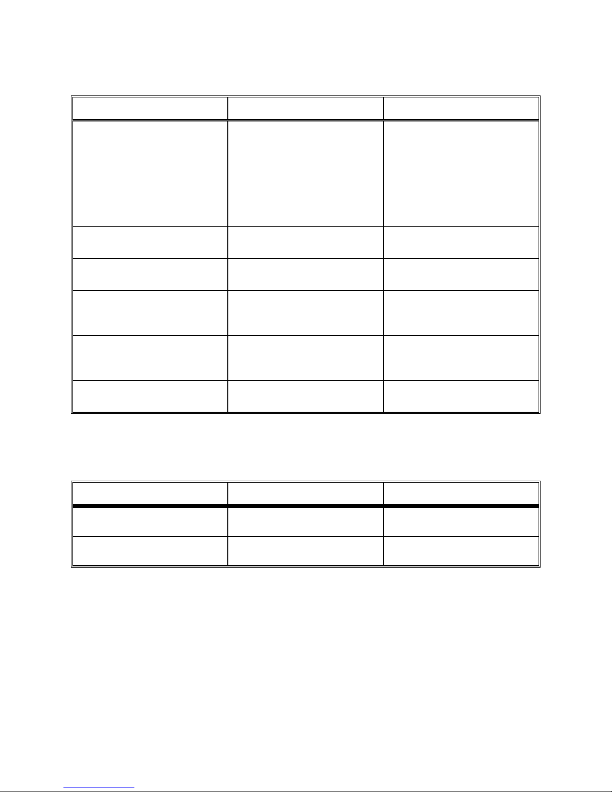
The following is a list of error codes for the Model 30 and Model 30M. The Model 30M also has
additional error codes (see the following page).
SYMPTOM POSSIBLE CAUSE ACTION
1. Instrument will not turn on
2. Instrument will not calibrate A. Incorrect calibration procedure
3. Instrument "loc k s up"
4. Instrument readings are inaccurate D. Calibration is required
5. LCD displays "LO BAT"
6. Main Display reads “OVEr” I. Conductivity Reading is >200 mS
A. Low battery v olta g e
B. Batteries installed wrong
C. Meter requires service
B. Cell needs cleaning
C. Instrument requires Service
A. Instrument has received a shock
B. Batteries are low or damaged
C. System requires service
E. Cell is contaminated
F. Temperature coefficient has been
set incorrectly
G. Reference temperature incorrect
H. Readings are or are not temperature
compensated.
A. Batteries are low or damaged
o
J. Temp. Reading is > 95
K. Temp. Reading is <-5
L. Salinity reading is > 80 ppt
C
o
C
A. Replace batteries
B. Check battery polarity.
C. Return system f or se rvic e
A. See section 5
B. See section 8
C. Return system for service
A. Remove ba tte ry lid, wait 15 seconds
for reset, replace lid.
B. Replace batteries
C. Return system for service
D. See section 5
E. See section 8
F. See section 6
G. See section 6
H. See section 3
Measurements
A. Replace batteries
I. In all cases, check calibration
values and procedure; check
Advanced Setup settings .
J. If each of these is set correctly,
return system for service.
Calibration
Maintenance
Calibration
Maintenance
Advanced Setup
Advanced Setup
Making
7. Main Display reads “Undr”
8. Main Display reads “rErr” N. User has selected manual ranging &
9. Main Display reads “PErr” O. Incorrect sequence of key stroke s A. Refer to manual section which
YSI, Incorporated Model 30/30M 27
M. During calibration, calculated cell
constant is >K=5.25
A. During calibration, calculated cell
constant is <K=4.9
sample exceeds selected range
A. Recalibrate instrum ent using k nown
good conductivity st a nda rd
B. Follow cell cleaning procedure see
section 8
K. Use the mode key to select a higher
or lower manua l ra nge, or to set
system to Autorang ing .
provides step by s te p pr oc e dure s
for the function you a r e a tte mpting.
Maintenance
.
Page 32
Troubleshooting Section 9
SYMPTOM POSSIBLE CAUSE ACTION
10. Main Display reads “LErr”
11. Main Display reads “Err”
Secondary Displa y reads “ra”
12. Main Display reads “Err”
Secondary Dis play reads “ro”
13. Secondary Displa y reads “ovr”
14. Secondary Dis play reads “udr”
15. Secondary Display reads “rEr” A. Tempera tur e jumper is set to o F and
A. In specifi c c onduc ta nc e mode,
temperature exceeds the values
computed using use r de fined
temperature coefficient and/or
reference temperature
B. During calibration, temperature
exceeds the values computed using
user defined temperature coefficient
and/or reference temperature
A. System has failed its RAM test check
procedure
A. System has failed its ROM test check
procedure
A. Temperature is > 95o C
A. Temperature is < -5o C
reading is >199.9
o
F but < 203 o F
A. & B. Adjust user de f i ned
temperature coefficient and/or
reference temperature (See section
6
Advanced Setup
A. Turn instrume nt O FF a nd bac k O N .
B. Return the system for service.
A. Turn instrume nt O FF a nd bac k O N .
B. Return the system for service.
A. Read solution of lower te mperature
B. Return system for service
C. Replace Probe/Cable assy.
A. Read solution of higher temperature
B. Return system for service
C. Replace Probe/Cable assy.
A. Set jumper to read
B. Return system for service
)
o
C.
The Model 30M has additional error codes as follows:
SYMPTOM POSSIBLE CAUSE ACTION
1. Readings on main dis pla y don’t
change
2. Main Display reads “nOnE” A. During recall, no data is currently
YSI, Incorporated Model 30/30M 28
A. Meter is in recall mode .
stored in memory.
A. Press MODE key to return to Norma l
Operation
A. Store data before attempting to recall
Page 33

Warranty and Repair Section 10
SECTION 10 WARRANTY AND REPAIR
YSI Model 30 Salinity, Conductivity and Temperature Meters are warranted for two years from date of
purchase by the end user against defects in materials and workmanship. YSI Model 30 probes and cables
are warranted for one year from date of purchase by the end user against defects in material and
workmanship. Within the warranty period, YSI will repair or replace, at its sole discretion, free of charge,
any product that YSI determines to be covered by this warranty.
To exercise this warranty, write or call your local YSI representative, or contact YSI Customer Service in
Yellow Springs, Ohio. Send the product and proof of purchase, transportation prepaid, to the Authorized
Service Center selected by YSI. Repair or replacement will be made and the product returned,
transportation prepaid. Repaired or replaced products are warranted for the balance of the original
warranty period, or at least 90 days from date of repair or replacement.
Limitation of Warranty
This Warranty does not apply to any YSI product damage or failure caused by (i) failure to install,
operate or use the product in accordance with YSI’s written instructions, (ii) abuse or misuse of the
product, (iii) failure to maintain the product in accordance with YSI’s written instructions or standard
industry procedure, (iv) any improper repairs to the product, (v) use by you of defective or improper
components or parts in servicing or repairing the product, or (vi) modification of the product in any way
not expressly authorized by YSI.
THIS WARRANTY IS IN LIEU OF ALL OTHER WARRA NTIES, EXPRESSED OR IMPLIED, INCL UDING ANY
WARRANTY OF MERCHANTABILITY OR FITNESS FOR A PARTICULAR PURPOSE. YSI’s L IA BIL ITY
UNDER THIS WARRANTY IS LIMITED TO REPAIR OR REPLACEMENT OF THE PRODUCT, AND THIS
SHALL BE YOUR SOLE AND EXCL USIVE REMEDY FOR A NY DEFEC TIVE PRODUCT COVERED BY THIS
WARRANTY. IN NO EVENT SHALL YSI BE LIABLE FOR A NY SPECIAL, INDIRECT, INCIDENTAL OR
CONSEQUENTIAL DAMAGES RESULTING FROM ANY DEFECTIVE PRODUCT COVERED BY THIS
WARRANTY.
YSI, Incorporated Model 30/30M 29
Page 34
Warranty and Repair Section 10
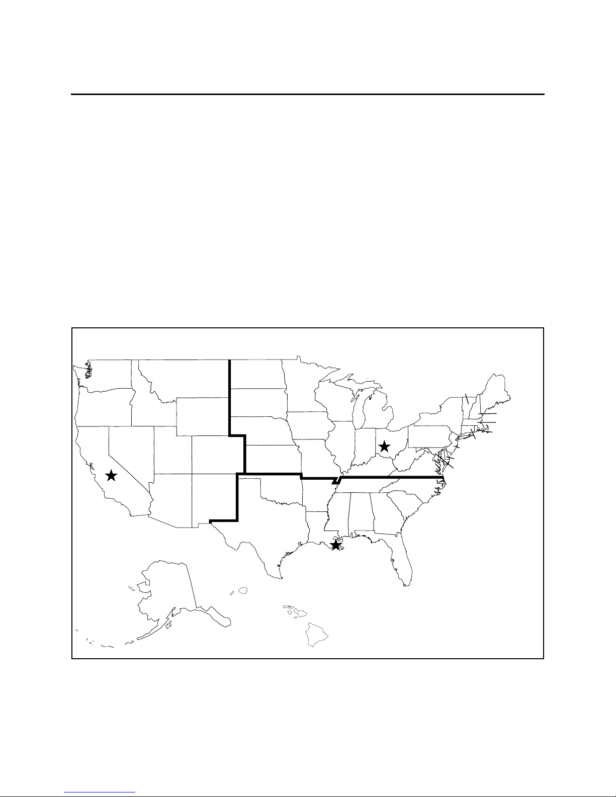
AUTHORIZED U.S. SERVICE CENTERS
North Region
YSI Incorporated • Repair Center • 1725 Brannum Lane • Yellow Springs, Ohio • 45387
Phone: (800) 765-4974 • (937) 767-7241• E-Mail: [email protected]
South Region
C.C. Lynch & Associates • 212 E. 2nd Street • Suite 203 • Pass Christian, Mississippi • 39571
Phone: (800) 333-2252 • (228) 452-4612 • Fax: (228) 452-2563
East Region
YSI Massachusetts, Inc. • 13 Atlantis Drive • Marion, MA • 02738 •Phone: (508)748-0366 • Fax
(508)748-2543
West Region
EnviroServices & Repair • 1110 Burnett Avenue, Suite D • Concord, CA • 94520 • Phone:
(800)550-5875 • Fax: (510)674-8655
est
North
Colorado
North aota
South aota
Nerasa
exas
ansas
Olahoma
Minnesota
owa
Missouri
Aransas
isconsin
Louisiana
llinois
ennessee
Mississippi
Alaama
ndiana
entucy
Michian
Georia
Ohio
est
irinia
South
Carolina
ennsylvania
irinia
North
Carolina
New Yor
ermont
elaware
Maryland
Connecticut
New ersey
East
Maine
New ampshire
Massachusetts
Rhode sland
ashinton
Oreon
California
Nevada
daho
tah
Ariona
Montana
yomin
New Mexico
•
•
Alasa
est
YSI, Incorporated Model 30/30M 30
lorida
South
awaii
est
Page 35

Warranty and Repair Section 10
INTERNATIONAL SERVICE CENTERS
YSI Incorporated • Repair Center • 1725 Brannum Lane • Yellow Springs, Ohio • 45387
Phone: (937) 767-7241• E-Mail: [email protected]
Lynchford House • Lynchford Lane • Farnborough • Hampshire • GU146LT • Phone: (44-1252)
514711 • Fax: (44-1252) 511855 • Tlx: 858210
Sakura – Building 6-5-6-13 • Shinjuku, Shinjuku-ku, Tokyo • 160 • Phone: (81-3) 5360-3561
Fax: (81-3) 5360-3565
SPECIALTY SERVICE CENTERS
Aquaculture
Aquatic Eco Systems, Inc. • 1767 Benbow Court • Apopka, Florida • Phone: (407) 886-3939
Fax: ( 407) 886-6787
Aquacenter • 166 Seven Oaks Road • Leland, Mississippi • 38756 • Phone: (601) 378-2861 • Fax:
(601) 378-2862
•
•
•
Wastewater
Q.C. Services • P.O. Box 68 • Harrison, Maine • 04040 • Phone: (207) 583-2980
Q.C. Services • P.O. Box 14831 • Portland, Oregon • 97293 • Phone: (503) 236-2712
YSI, Incorporated Model 30/30M 31
Page 36

Warranty and Repair Section 10
CLEANING INSTRUCTIONS
NOTE: Before they can be serviced, equipment exposed to biological, radioactive, or toxic
materials must be cleaned and disinfected.
Biological contamination is presumed for any instrument, probe, or other device that has been
used with body fluids or tissues, or with waste water. Radioactive contamination is presumed for
any instrument, probe or other device that has been used near any radioactive source.
If an instrument, probe, or other part is returned or presented for service without a Cleaning
Certificate, and if in our opinion it represents a potential biological or radioactive hazard, our
service personnel reserve the right to withhold service until appropriate cleaning,
decontamination, and certification has been completed. We will contact the sender for
instructions as to the disposition of the equipment. Disposition costs will be the responsibility of
the sender.
When service is required, either at the user's facility or at YSI, the following steps must be taken
to insure the safety of our service personnel.
1. In a manner appropriate to each device, decontaminate all exposed surfaces, including any
containers. 70% isopropyl alcohol or a solution of 1/4 cup bleach to 1 gallon tap water are
suitable for most disinfecting. Instruments used with waste water may be disinfected with
.5% Lysol if this is more convenient to the user.
2. The user shall take normal precautions to prevent radioactive contamination and must use
appropriate decontamination procedures should exposure occur.
3. If exposure has occurred, the customer must certify that decontamination has been
accomplished and that no radioactivity is detectable by survey equipment.
4. Any product being returned to the YSI Repair Center, should be packed securely to prevent
damage.
5. Cleaning must be completed and certified on any product before returning it to YSI.
YSI, Incorporated Model 30/30M 32
Page 37

Warranty and Repair Section 10
PACKING INSTRUCTIONS
1. Clean and decontaminate items to insure the safety of the handler.
2. Complete and include the Cleaning Certificate.
3. Place the product in a plastic bag to keep out dirt and packing material.
4. Use a large carton, preferably the original, and surround the product completely with packing
material.
5. Insure for the replacement value of the product.
Cleaning Certificate
Organization
Department
Address
City State Zip
Country Phone
Model No. of Device Lot Number
Contaminant (if known)
Cleaning Agent(s) used
Radioactive Decontamination Cer tified?
(Answer only if there has been radi oacti v e exposure)
Yes No
Cleaning Certified By
Name Date
YSI, Incorporated Model 30/30M 33
Page 38

Warranty and Repair Section 10
YSI, Incorporated Model 30/30M 34
Page 39

APPENDIX A REQUIRED NOTICE
The Federal Communications Commission defines this product as a computing device and requires
the following notice:
This equipment generates and uses radio frequency energy and if not installed and used properly,
may cause interference to radio and television reception. There is no guarantee that interference will
not occur in a particular installation. If this equipment does cause interference to radio or television
reception, which can be determined by turning the equipment off and on, the user is encouraged to
try to correct the interference by one or more of the following measures:
•
•
•
•
re-orient the receiving antenna
relocate the computer with respect to the receiver
move the computer away from the receiver
plug the computer into a different outlet so that the computer and receiver are on
different branch circuits.
If necessary, the user should consult the dealer or an experienced radio/television technician for
additional suggestions. The user may find the following booklet, prepared by the Federal
Communications Commission, helpful: "How to Identify and Resolve Radio-TV Interference
Problems." This booklet is available from the U.S. Government Printing Office, Washington, D.C.
20402, Stock No. 0004-000-00345-4.
YSI, Incorporated Model 30/30M 35
Page 40

Warranty and Repair Section 10
YSI, Incorporated Model 30/30M 36
Page 41
APPENDIX B ACCESSORIES AND REPLACEMENT PARTS
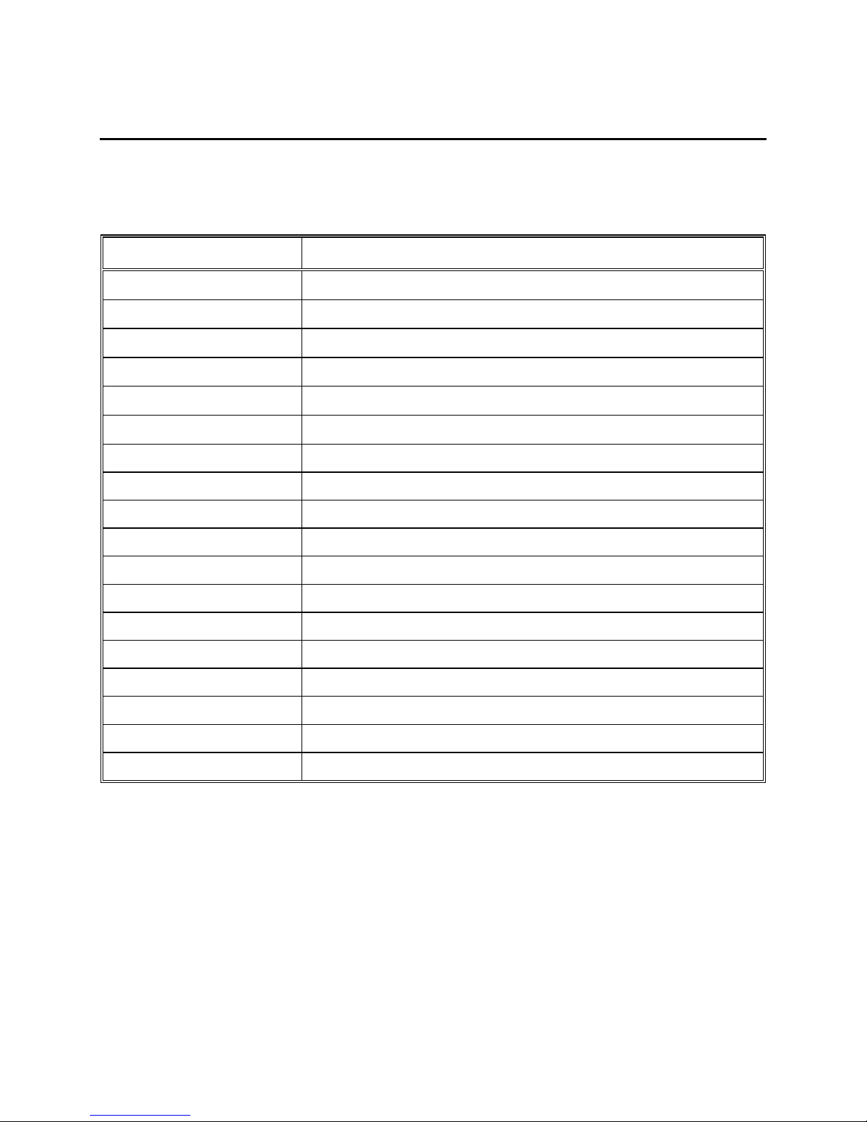
The following parts and accessories are available from YSI or any Franchise Dealer authorized by
YSI.
YSI Order Number Description
3161
3163
3165
3167
3168
3169
5520 Carrying C a s e
110030 Replacement Probe & Cable As s embly (10 feet)
110031 Replacement Probe & Cable As s embly (25 feet)
110032 Replacement Probe & Cable As s embly (50 feet)
030131 Replacement Front Cas e C over
055242 Replacement Rear Case C ov er
055244 Replacement Battery Cov er Kit
055204 Replacement Case Gask et an d S crew, Model 30
055219 Storage Chamber S pon g e
Conductivity Calibrator Soluti on 1,000 µS/cm (1 Quart)
Conductivity Calibrator Soluti on 10,000 µS/cm (1 Quart)
Conductivity Calibrator Solut ion 100,000 µS/cm (1 Quart)
Conductivity Calibrator Soluti on 1,000 µS/cm (8 pints)
Conductivity Calibrator Soluti on 10,000 µS/cm (8 pints)
Conductivity Calibrator Soluti on 50,000 µS/cm (8 pints)
038213 Replacement Electrode Cleanin g Bru sh
030133 Replacement PCB Ass y., Model 30
030155 Replacement PCB Ass y., Model 30M
YSI, Incorporated Model 30/30M 37
Page 42

Accessories and Replacemen t Parts Appendix B
YSI, Incorporated Model 30/30M 38
Page 43
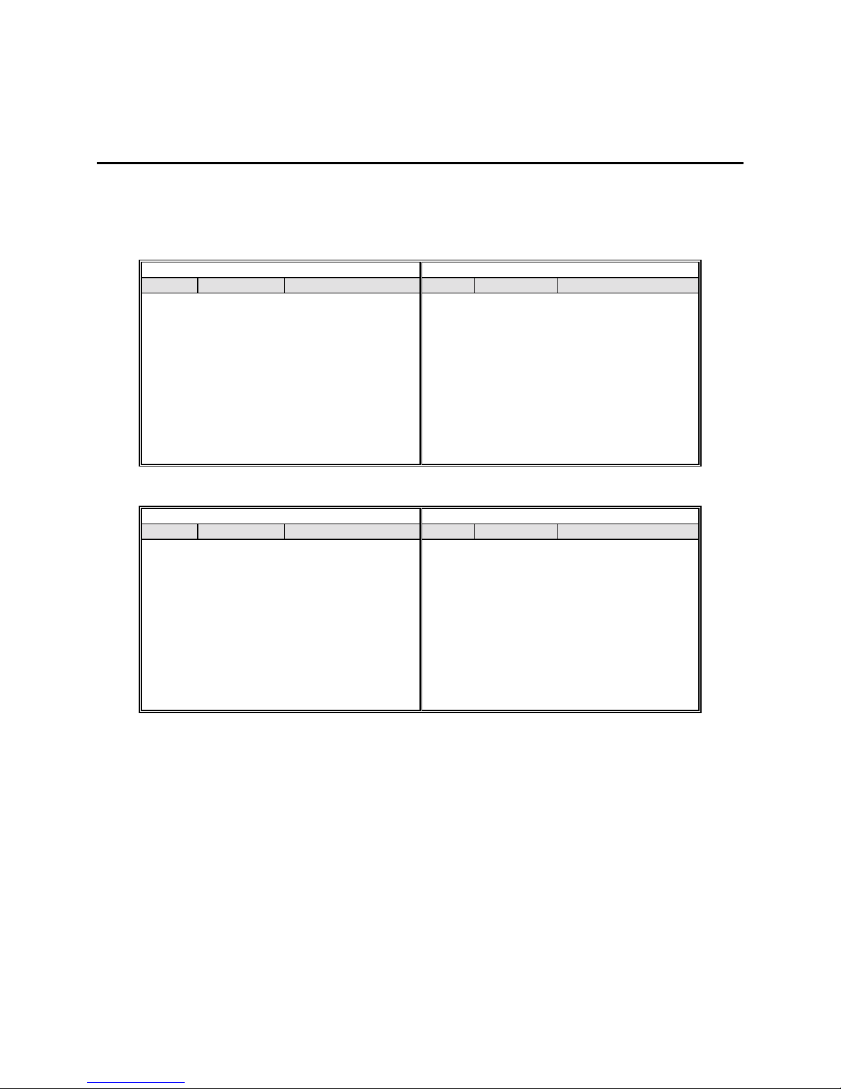
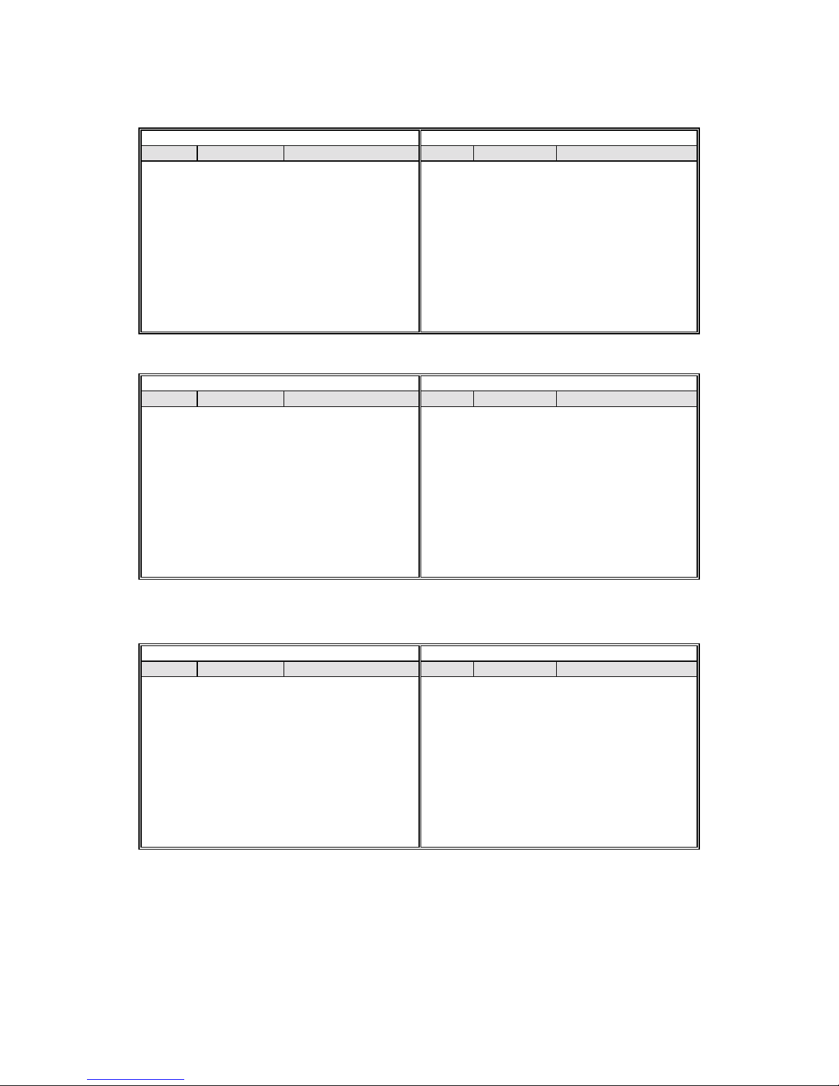
APPENDIX C TEMPERATURE CORRECTION
This data is for typical applications of the YSI sondes.
A. Potassium Chloride** (KCl)
Concentration: 1 mole/liter Concentration: 1 x 10⁻¹ mole/liter
C
°
0 65.10 1.67 0 7.13 1.78
5 73.89 1.70 5 8.22 1.80
10 82.97 1.72 10 9.34 1.83
15 92.33 1.75 15 10.48 1.85
20 101.97 1.77 20 11.65 1.88
25 111.90 1.80 25 12.86 1.90
C
°
0 0.773 1.81 0 0.080 1.84
5 0.892 1.84 5 0.092 1.88
10 1.015 1.87 10 0.105 1.92
15 1.143 1.90 15 0.119 1.96
20 1.275 1.93 20 0.133 1.99
25 1.412 1.96 25 0.147 2.02
30 1.553 1.99 30 0.162 2.05
35 1.697 2.02 35 0.178 2.07
37.5 1.771 2.03 37.5 0.186 2.08
40 1.845 2.05 40 0.194 2.09
45 1.997 2.07 45 0.210 2.11
50 2.151 2.09 50 0.226 2.13
mS/cm
Concentration: 1 x 10⁻² mole/liter Concentration: 1 x 10⁻³ mole/liter
mS/cm
%/°C (to 25°C)
%/°C (to 25°C)
C
°
30 14.10 1.93
35 15.38 1.96
37.5 16.04 1.98
40 16.70 1.99
45 18.05 2.02
50 19.43 2.04
C
°
mS/cm
mS/cm
%/°C (to 25°C)
%/°C (to 25°C)
** Charts developed by interpolating data from
YSI, Incorporated Model 30/30M 39
International Critical Tables
, Vol. 6, pp. 229-253, McGraw-Hill Book Co., NY.
Page 44
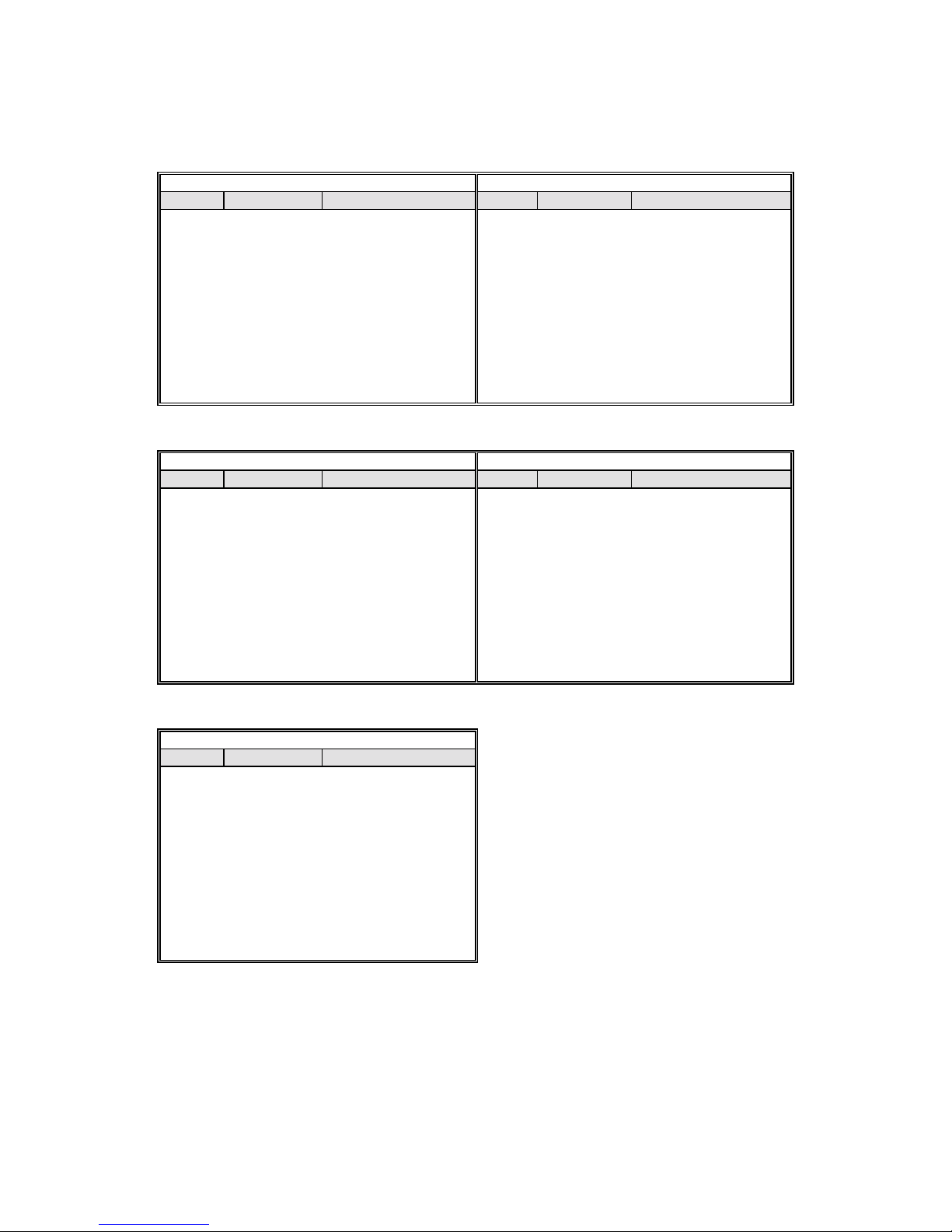
Temperature Coefficient Appendix C
B. Sodium Chloride
C
°
0 134.50 1.86 0 25.90 1.78
5 155.55 1.91 5 29.64 1.82
10 177.90 1.95 10 33.61 1.86
15 201.40 1.99 15 37.79 1.90
20 225.92 2.02 20 42.14 1.93
25 251.30 2.05 25 46.65 1.96
30 277.40 2.08 30 51.28 1.99
C
°
0 5.77 1.83 0 0.632 1.87
5 6.65 1.88 5 0.731 1.92
10 7.58 1.92 10 0.836 1.97
15 8.57 1.96 15 0.948 2.01
20 9.60 1.99 20 1.064 2.05
25 10.66 2.02 25 1.186 2.09
30 11.75 2.04 30 1.312 2.12
35 12.86 2.06 35 1.442 2.16
37.5 13.42 2.07 37.5 1.508 2.17
40 13.99 2.08 40 1.575 2.19
45 15.14 2.10 45 1.711 2.21
50 16.30 2.12 50 1.850 2.24
*
(NaCl)
Saturated solutions at all temperatures Concentration: 0.5 mole/liter
mS/cm
Concentration: 1 x 10⁻¹ mole/liter Concentration: 1 x 10⁻² mole/liter
mS/cm
%/°C (to 25°C)
%/°C (to 25°C)
C
°
35 56.01 2.01
37.5 58.40 2.02
40 60.81 2.02
45 65.65 2.04
50 70.50 2.05
C
°
mS/cm
mS/cm
%/°C (to 25°C)
%/°C (to 25°C)
Concentration: 1 x 10⁻³ mole/liter
C
°
0 0.066 1.88
5 0.076 1.93
10 0.087 1.98
15 0.099 2.02
20 0.111 2.07
25 0.124 2.11
30 0.137 2.15
35 0.151 2.19
37.5 0.158 2.20
40 0.165 2.22
45 0.180 2.25
50 0.195 2.29
* Charts developed by interpolating data from the
mS/cm
%/°C (to 25°C)
CRC Handbook of Chemistry and Physics
, 42nd ed., p. 2606, The Chemical Rubber Company, Cleveland.
YSI, Incorporated Model 30/30M 40
Page 45
Temperature Coefficient Appendix C
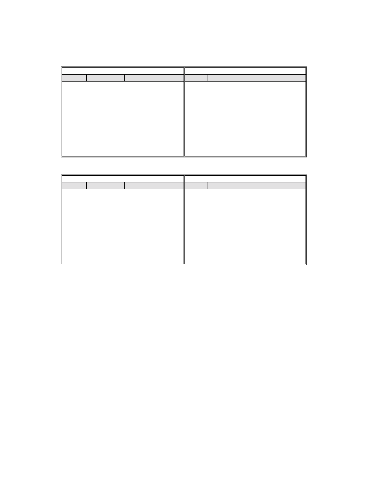
C. Lithium Chloride
C
°
0 39.85 1.82 0 5.07 1.87
5 46.01 1.85 5 5.98 1.85
10 52.42 1.89 10 6.87 1.85
15 59.07 1.92 15 7.75 1.85
20 65.97 1.95 20 8.62 1.85
25 73.10 1.98 25 9.50 1.86
30 80.47 2.02 30 10.40 1.88
35 88.08 2.05 35 11.31 1.91
37.5 91.97 2.07 37.5 11.78 1.92
40 95.92 2.08 40 12.26 1.94
45 103.99 2.11 45 13.26 1.98
50 112.30 2.15 50 14.30 2.02
C
°
0 0.567 1.88 0 0.059 1.93
5 0.659 1.92 5 0.068 2.03
10 0.755 1.96 10 0.078 2.12
15 0.856 2.00 15 0.089 2.19
20 0.961 2.04 20 0.101 2.25
25 1.070 2.08 25 0.114 2.28
30 1.183 2.12 30 0.127 2.31
35 1.301 2.16 35 0.140 2.32
37.5 1.362 2.18 37.5 0.147 2.32
40 1.423 2.20 40 0.154 2.31
45 1.549 2.24 45 0.166 2.29
50 1.680 2.28 50 0.178 2.25
*
(LiCl)
Concentration: 1 mole/liter Concentration: 1 x 10⁻¹ mole/liter
mS/cm
Concentration: 1 x 10⁻² mole/liter Concentration: 1 x 10⁻³ mole/liter
mS/cm
%/°C (to 25°C)
%/°C (to 25°C)
C
°
C
°
mS/cm
mS/cm
%/°C (to 25°C)
%/°C (to 25°C)
D. Potassium Nitrate** (KNO3)
Concentration: 1 x 10⁻¹ mole/liter Concentration: 1 x 10⁻² mole/liter
C
°
0 6.68 1.78 0 0.756 1.77
5 7.71 1.79 5 0.868 1.80
10 8.75 1.81 10 0.984 1.83
15 9.81 1.83 15 1.105 1.86
20 10.90 1.85 20 1.229 1.88
25 12.01 1.87 25 1.357 1.90
30 13.15 1.90 30 1.488 1.93
35 14.32 1.92 35 1.622 1.95
37.5 14.92 1.94 37.5 1.690 1.96
40 15.52 1.95 40 1.759 1.97
45 16.75 1.97 45 1.898 1.99
50 18.00 2.00 50 2.040 2.01
* Charts developed by interpolating data from the
** Charts developed by interpolating data from
mS/cm
International Critical Tables
%/°C (to 25°C)
CRC Handbook of Chemistry and Physics
, Vol. 6, pp. 229-253, McGraw-Hill Book Co., NY.
C
°
mS/cm
, 42nd ed., p. 2606, The Chemical Rubber Company, Cleveland.
%/°C (to 25°C)
YSI, Incorporated Model 30/30M 41
Page 46
Temperature Coefficient Appendix C
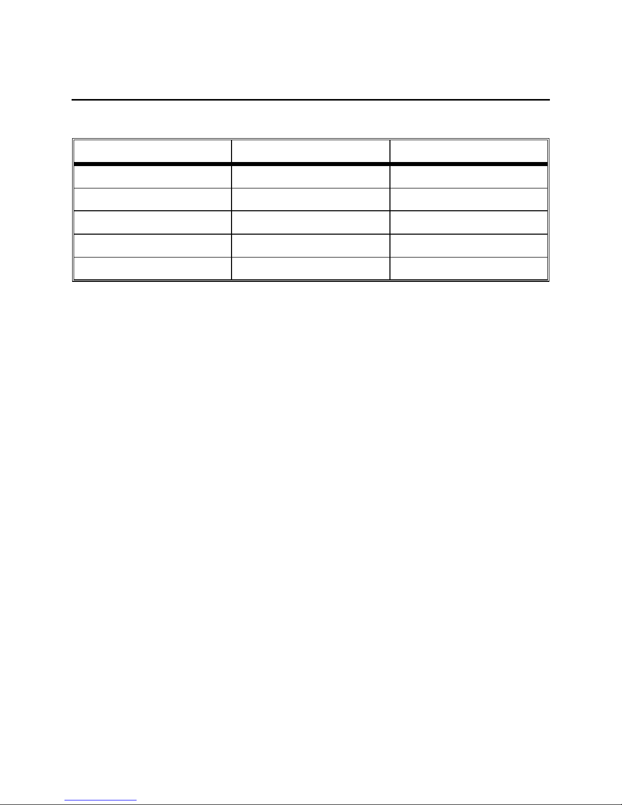
E. Ammonium Chloride
C
°
0 64.10 1.60 0 6.96 1.82
5 74.36 1.53 5 7.98 1.88
10 83.77 1.45 10 9.09 1.93
15 92.35 1.37 15 10.27 1.97
20 100.10 1.29 20 11.50 2.00
25 107.00 1.21 25 12.78 2.03
C
°
0 0.764 1.84 0 0.078 1.88
5 0.889 1.86 5 0.092 1.90
10 1.015 1.88 10 0.105 1.91
15 1.144 1.91 15 0.119 1.93
20 1.277 1.94 20 0.133 1.95
25 1.414 1.97 25 0.148 1.98
30 1.557 2.02 30 0.162 2.01
35 1.706 2.06 35 0.178 2.04
37.5 1.782 2.08 37.5 0.186 2.06
40 1.860 2.10 40 0.194 2.07
45 2.020 2.14 45 0.210 2.11
50 2.186 2.18 50 0.227 2.15
*
(NH4Cl)
Concentration: 1 mole/liter Concentration: 1 x 10⁻¹ mole/liter
mS/cm
Concentration: 1 x 10⁻² mole/liter Concentration: 1 x 10⁻³ mole/liter
mS/cm
%/°C (to 25°C)
%/°C (to 25°C)
C
°
30 14.09 2.06
35 15.43 2.07
37.5 16.10 2.08
40 16.78 2.08
45 18.12 2.09
50 19.45 2.09
C
°
mS/cm
mS/cm
%/°C (to 25°C)
%/°C (to 25°C)
* Charts developed by interpolating data from the
CRC Handbook of Chemistry and Physics
, 42nd ed., p. 2606, The Chemical Rubber Company, Cleveland.
YSI, Incorporated Model 30/30M 42
Page 47
APPENDIX D CONVERSION CHART
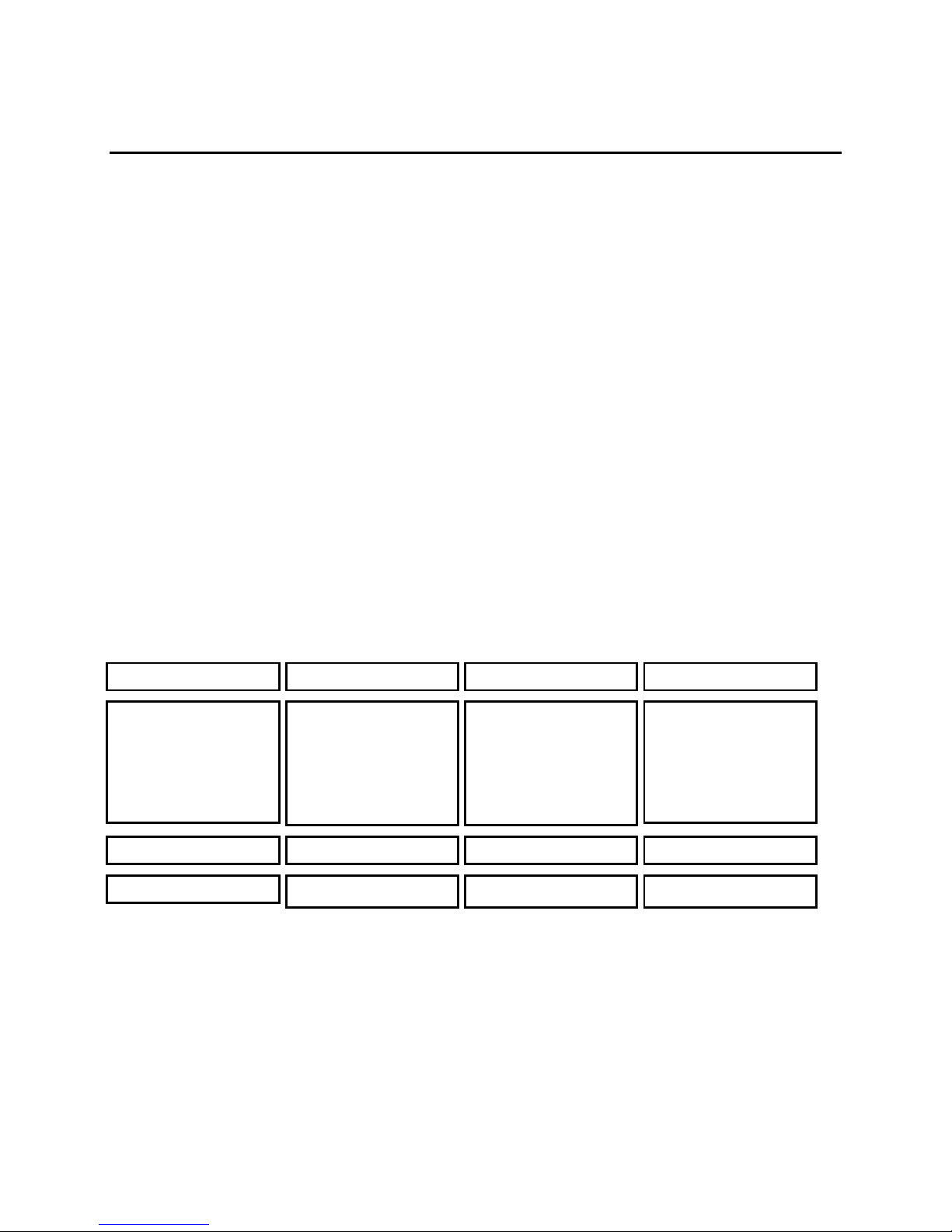
To Convert From To Equation
Feet Meters Multiply by 0.3048
Meters Feet Multiply by 3.2808399
Degrees Celsius Degrees Fahrenheit
Degrees Fahrenheit Degrees Celsius
9/5×(oC)+32
5/9×(oF-32)
Milligrams per liter (mg/l) Parts per million (ppm) Multiply by 1
YSI, Incorporated Model 30/30M 43
Page 48

Conversion Chart Appendix D
YSI, Incorporated Model 30/30M 44
Page 49

APPENDIX E GLOSSARY
ampere
amplitude
(A) - SI unit of electric current
- The maximum deviation of an alternating current from its aver ag e va lue during its
cycle.
ASTM
calibrate
- American Society for Testing and Materials
- To determine, check, or rectify the g ra duation of a ny instrument giving quantitative
measurements.
calibrator solution
capacitance
(C) - The ratio of the total charge on an isolated conductor to its potential; the property
- A solution of known value used to calibrate.
of being able to collect a charge of electricity. C = Q/V.
capacitor
cell constant
- An electrical component able to accumulate and hold an electric charge.
(K) - The ratio of the distance between two electrodes to the area normal to the
current flow. K=d/A.
- Abbreviation for the centimeter-gram-second system of units. Mostly superseded by SI units.
cgs
conductance
(k) - The ratio of the current in a conductor to the potential difference between its
ends; the ability of a conductor to transmit current; the reciprocal of resistance. The SI unit is
siemens (S), also measured in mhos.
conductivity
(ℵ) - The ratio of the current density in a conductor to the electric field causing the
current to flow; the inverse of resistivity; the conductance between opposite faces of a cube of the
measured material of 1 cm (cgs units) or 1 m (SI units) edge. Measured in mhos/cm (cgs units) or
S/m (SI units)
conductivity cell
current
electrode
ion
mks
mho
micro
milli
NIST
(I) - The rate of flow of an electric charge, usually expressed in amperes.
- A conductor whereby an electric current enters or leaves a liquid, gas, or vacuum.
- Any atom or molecule that has an electric charge due to the loss or gain of valence electrons.
- Abbreviation for the meter-kilogram-second system of units.
- A unit of conductance; the reciprocal of an ohm.
(µ) - The metric prefix indicating 10-6.
(m) - The metric prefix indicating 10-3.
- National Institute of Standards and Technology . The US g overnment ag ency that defines
- Any cell with electrodes used to measure the conductivity of liquid.
measurement standards in the United States.
(Ω) - SI unit of resistance
ohm
OIML
YSI, Incorporated Model 30/30M 45
- Organisation Internationale de Métrologie L é g ale
Page 50

Glossary Appendix E
polarization
- The separation of the positive and negative c harg e s of a mole cule by an external
agent.
- A trademark name for heat-resistant and chemical-resistant glass.
Pyrex
reference voltage
- Système International
SI
siemens
(S) - SI unit of electrical conductance; the reciprocal of an ohm; equivalent to a mho.
temperature correction
- A closely controlled d.c. or a.c. voltage used as a reference.
- An adjustment made to a measurement to compensate for the diffe rence
between the measured and nominal temperatures.
temperature coefficient
- The change in any pa rticular physical quantity per deg r ee chang e in
temperature.
voltage
- Electromotive force or potential expressed in volts.
YSI, Incorporated Model 30/30M 46
Page 51
APPENDIX F GENERAL SPECIFICATIONS
Probe Operating Environment
Medium: fresh, sea, or polluted water and most other liquid solutions.
o
Temperature: -5 to +95
Depth: 0 to 10, 0 to 25, or 0-50 feet (depending on cable length)
Meter Ambient Operating/Storage Temperature:
C
-10 to +50
o
C
Material:
ABS, Stainless Steel, and other materials.
Dimensions:
Height: 9.5 inches (24.13 cm)
Thickness: 2.2 inches (5.6 cm)
Width: 3.5 inches max. (8.89 cm)
Weight: 1.7 pounds (w/ 10’ cable) (0.77 kg)
Display 2.3"W x 1.5"L (5.8 cm W x 3.8 cm L)
Power:
9 VDC - 6 AA-size Alkaline Batteries (included)
Approximately 100 hours operation from each new set of batteries
Water Tightness:
Meets or exceeds IP65 standards
Extensive testing of the YSI Mode l 30 indicate s the following ty pic al perform anc e:
MEASUREMENT RANGE RESOLUTION ACCURACY
Conductivity
0 to 499.9 µS/cm
0 to 4999 µS/cm
0 to 49.99 mS/cm
0.1 µS/cm
1.0 µS/cm
0.01 mS/cm
0.5% FS*
±
0.5% FS
±
0.5% FS
±
0 to 200.0 mS/cm
Salinity 0-80 ppt 0.1 ppt
Temperature
For 50 Ft. cables, specification is for specific conductance > 100
*
-5 to 95o C 0.1o C
Adjustable Reference Temperature:
Adjustable Temperature Compensation Factor:
Temperature Compensation:
Range:
Data Storage:
YSI, Incorporated Model 30/30M 47
User selected or Autoranging
50 points with ID (Model 30M only )
15o C - 25o C
Automatic
0.1 mS/cm
0% - 4%
0.5% FS
±
2%, or ± 0.1 ppt
±
0.1o C (±1 lsd)
±
S/cm
µ
Page 52

1700/1725 Brannum Lane
Yellow Springs, Ohio 45387 USA
(800) 765-4974 (937) 767-7241
FAX: (937) 767-9320
Website: http://www.ysi.com
E-Mail: [email protected]
DRW # A30136D
May 1998
Item # 030136
 Loading...